

January 1987 FORM: OM-1516F
IMPORTANTE Read and understand the entire contents of both this manual and the power source manual used with this unit, with special emphasis on the safety material throughout both manuals, before installing, operating, or maintaining this equipment. This unit and these instructions are for use only by persons trained and experienced in the safe operation of welding equipment. Do not allow untrained persons to install, operate, or maintain this unit. Contact your distributor if you do not fully understand these instructions.
Effective With Serial No. JG070373
MODEL SWINGARC® SINGLE 12 SWINGARC® SINGLE 16

OWNER'S MANUAL

MILLER ELECTRIC MFG. CO.
718 S. BOUNDS ST, P.O. Box 1079 APPLETON, WI 54912 USA
ADDITIONAL COPY PRICE $1.20
NWSA CODE NO. 4579 PRINTED IN U.S.A.
LIMITED WARRANTY
EFFECTIVE: OCTOBER 1, 1986
This warranty supersedes all previous MILLER warranties and is exclusive with no other guarantees or warranties expressed or implied.
The for the fo
LIMITED WARRANTY - Subject to the terms and conditions hereof, Miller Electric Mfg. Co., Appleton, Wisconsin warrants to its Distributor/Dealer that all new and unused Equipment furnished by Miller is free from defect in workmanship and material as of the time and place of delivery by Miller. No warranty is made by Miller with respect to engines, trade accessories or other items manufactured by others. Such engines, trade accessories and other items are sold subject to the warranties of their respective manufacturers, if any . All engines are warranted by their manufacturer for one year from date of original purchase, except Tecumseh engines which have a two year warranty.
Except as specified below, Miller's warranty does not apply to components having normal useful life of less than one (1) year, such as spot welder tips, relay and contactor points, MILLERMATIC parts that come in contact with the welding wire including nozzles and nozzle insulators where failure does not result from defect in workmanship or material.
Miller shall be required to honor warranty claims on warranted Equipment in the event of failure resulting from a defect within the following periods from the date of delivery of Equipment to the original user:
- 1. Arc welders, power sources, robots, and components . 1 year
- 2. Load banks ..... 1 vear
- 3. Original main power rectifiers ...... 3 years (labor - 1 year only)
- 4. All welding guns, feeder/guns and plasma torches . 90 days
- 5. All other Millermatic Feeders ....................................
- 6. Replacement or repair parts, exclusive of labor . . 60 days
- 7. Batteries ...... 6 months
provided that Miller is notified in writing within thirty (30) days of the date of such failure.
As a matter of general policy only, Miller may honor claims submitted by the original user within the foregoing periods.
In the case of Miller's breach of warranty or any other duty with respect to the quality of any goods, the exclusive remedies therefore shall be, at Miller's option (1) repair or (2) replacement or, where authorized in writing by Miller in appropriate cases, (3) the reasonable cost of repair or replacement at an authorized Miller service station or (4) payment of or credit for the purchase price (less reasonable depreciation based upon actual use) upon return of the goods at Customer's risk and expense. MILLER's option of repair or replacement will be F.O.B., Factory, at Appleton, Wisconsin, or F.O.B., at a MILLER authorized service facility, therefore, no compensation for transportation costs of any kind will be allowed. Upon receipt of notice of apparent defect or failure. Miller shall instruct the claimant on the warranty claim procedures to be followed.
∦ ¥
Ì.
14
Į.
15
W.
A.
Ÿ.
₩
J.
X
G.
1
1.
AF.
h
N.
الج
ANY EXPRESS WARRANTY NOT PROVIDED HEREIN AND ANY IMPLIED WARRANTY, GUARANTY OR REPRESENTA-TION AS TO PERFORMANCE, AND ANY REMEDY FOR BREACH OF CONTRACT WHICH, BUT FOR THIS PROVISION, MIGHT ARISE BY IMPLICATION, OPERATION OF LAW, CUSTOM OF TRADE OR COURSE OF DEALING. INCLUDING ANY IMPLIED WARRANTY OF MERCHANTABILITY OR OF FITNESS FOR PARTICULAR PURPOSE. WITH RESPECT TO ANY AND ALL EQUIPMENT FURNISHED BY MILLER IS EX-CLUDED AND DISCLAIMED BY MILLER.
EXCEPT AS EXPRESSLY PROVIDED BY MILLER IN WRITING, MILLER PRODUCTS ARE INTENDED FOR ULTIMATE PURCHASE BY COMMERCIAL/INDUSTRIAL USERS AND FOR OPERATION BY PERSONS TRAINED AND EXPERIENCED IN THE USE AND MAINTENANCE OF WEIDING FOUIPMENT AND NOT FOR CONSUMERS OR CONSUMER USE. MILLER'S WARRANTIES DO NOT EXTEND TO, AND NO RESELLER IS AUTHORIZED TO EXTEND MILLER'S WARRANTIES TO, ANY CONSUMER.
ERRATA SHEET
After this manual was printed, refinements in equipment design occurred. This sheet lists exceptions to data appearing later in this manual.
AMENDMENT TO SECTION 3 - INSTALLATION
Replace Sections 3-4 and 3-7 with the following:
3 - 4. INSTALLATION OF OPTIONAL WIRE REEL AND REEL-TYPE WIRE (Figure 3-3)
- 1. Remove retaining ring and if applicable wire reel assembly from hub.
- 2. Lay wire reel assembly flat on a table or floor.
- 3. Remove spanner nut from wire reel assembly.
- 4. Remove wire retainer, and install wire onto wire reel. Be sure that wire feeds off top of reel.
- 5. Reinstall wire retainer and spanner nut onto wire reel.
- 6. Slide wire reel assembly onto hub, and rotate assembly until hub guide pin is seated in reel.
- 7. Reinstall retaining ring onto hub.
Amend Figure 3 - 3. Reel Installation

AMENDMENT TO SECTION 6 - MAINTENANCE & TROUBLESHOOTING
Amend Figure 6 - 4. Circuit Diagram

Figure 6 - 4. Circuit Diagram For Models Effective With Serial No. JH262095
Add Figure 6 - 4a. Circuit Diagram For Motor Control Board PC1

Circuit Diagram No. A-083 267
Figure 6 - 4a. Circuit Diagram For Motor Control Board PC1 Effective With Serial No. JH262095 Thru JJ321896

Circuit Diagram No. A-120 065
Figure 6 - 4a. Circuit Diagram For Motor Control Board PC1 Effective With Serial No. JJ321897
Add Figure 6 - 5. Circuit Diagram For Optional Burnback Circuit Board
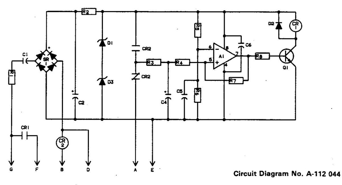
Figure 6 - 5. Circuit Diagram For Optional Burnback Circuit Board Effective With Serial No. JH222267
OM-1516F Page 3
| ** |
Dia.
Mkgs. |
Part
No. |
Replaced
With |
Description | Quantity |
|---|---|---|---|---|---|
| 4-3 | T1 | 047 818 | 114 308 | TRANSFORMER, control 115/24 (Eff w/JH222267). | 1 |
| 4-20 | CR1 | 034 841 | 109 006 | RELAY, enclosed 24 volts ac DPDT (Eff w/JH262095) | 1 |
| 5- | 037 289 | 037 813 | TRANSISTOR, UJT 50MA 35 volts | 1 | |
| C5 | 031 670 | CAPACITOR, ceramic 0.05 uf 500 volts dc (Eff w/JJ332372) | 1 | ||
| R2 | 035 825 | RESISTOR, carbon film 0.25 watt 1K ohm (Eff w/JJ332372) | 1 | ||
| 9-10 | 056 416 | 108 008 | REEL, wire (consisting of) | 1 | |
| 108 061 | . NUT, spanner-spool support | 1 | |||
| 108 858 | . RETAINER, spool-support | 1 | |||
| 108 857 | . SUPPORT, reel-support | 1 | |||
| 9-11 | |||||
| thru | • | ||||
| 10 | 047.046 | BURNBACK CONTROL (association of)(Eff ( 11)222227) | |||
| 11- | 047 946 | 112 020 | BURNBACK CONTROL (consisting of) (Eff W/JH222267) | 1 | |
| 112 020 | 112 030 | CIRCUIT CARD, timer (consisting of) (Prior to JJ328495) | 1 | ||
| Δ1 | 112 030 | 009 159 | Cincon CARD, amer (En w/JJ326455) (consisting on | 1 | |
| 112 233 | CAPACITOR noty film 1.5 of 250 volte de | 1 | |||
| C2 | 039 482 | CAPACITOR electrolyte 100 uf 35 volts dc | 1 | ||
| C4 | 091 791 | CAPACITOR, taptalum 15 uf 35 volts | 1 | ||
| C5.6 | 073 739 | CAPACITOR ceramic 0.1 uf 50 volts dc | 2 | ||
| CR1 | 090 875 | . RELAY, enclosed 12 volts dc SPDT (Prior to JJ328455) | 1 | ||
| CR1 | 117 535 | . RELAY, enclosed 12 volts dc SPDT (Eff w/JJ328455) | 1 | ||
| CR2 | 111 999 | RELAY, enclosed 115 volts ac SPDT | 1 | ||
| D1,3 | 028 293 | DiODE, zener 6.2 volts 1 watt | 2 | ||
| D2 | 026 202 | . DIODE, 1 amp 400 volts SP | 1 | ||
| Q1 | 037 200 | TRANSISTOR, NPN 200MA | 1 | ||
| R1 | 030 090 | RESISTOR, carbon 0.5 watt 47 ohm | 1 | ||
| R2 | 030 045 | RESISTOR, WW fixed 3.25 watt 100 ohm | 1 | ||
| R3 | 044 634 | RESISTOR, carbon film 0.25 watt 330 ohm | 1 | ||
| R4 | 044 789 | RESISTOR, carbon film 0.25 watt 100K ohm | 1 | ||
| R5 | 108 433 | RESISTOR, carbon film 0.25 watt 2.4K ohm | 1 | ||
| R6 | 072 560 | RESISTOR, carbon film 0.25 watt 1K ohm | 1 | ||
| R/ | 003 272 | RESISTOR, carbon film 0.25 watt 1 meg ohm | 1 | ||
|
K8
CD1 |
035 827 | RESISTOR, carbon film 0.25 watt 10K ohm | 1 | ||
| SRI | 035 841 | TEDMINIAL based 7.5 amp 200 volts | 1 | ||
| • | 79 | 040 100 | 1 | ||
| Π/ | 0/3 302 | HOUSING terminal header 7 ain | 1 | ||
| 040 104 | 1 | ||||
| 037 322 | PLUG connector keying | 1 | |||
| 040 207 | STAND_DEE No 6.22 v 2/8 v 1/4 hov |
ן
י |
|||
| 2 |
**First digit represents page no - digits following dash represent item no. BE SURE TO PROVIDE MODEL AND SERIAL NUMBER WHEN ORDERING REPLACEMENT PARTS.
TABLE OF CONTENTS
| Section No. | Page No. |
|---|---|
| SECTION 1 - SAFETY RULES FOR OPERATION OF ARC WELDING POWER | SOURCE |
|
1
1 7 11 |
| SECTION 2 - INTRODUCTION | |
|
13
13 13 |
| SECTION 3 - INSTALLATION |
| 3 - 1. | Location And Assembly | 14 |
|---|---|---|
| 3 - 2. | Installation Of Wire Support | 15 |
| 3 - 3. | Reinstallation Of Hub Assembly | 15 |
| 3 - 4. | Installation Of Wire Reel (Optional) | 16 |
| 3 - 5. | Installation Of Wire Guide Extension | 16 |
| 3 - 6. | Installation Of Spool-Type Wire | 16 |
| 3 - 7. | Installation Of Reel-Type Wire | 16 |
| 3 - 8. | Drive Motor Vent Screw | 16 |
| 3 - 9. | Drive Roll And Wire Guide Installation | 16 |
| 3-10. | Water Connections (Optional) | 18 |
| 3-11. | Welding Gun Connections To Drive Assembly | 18 |
| 3 -12. | Connections From Boom To Control Box | 20 |
| 3-13. | Pulley Adjustment | 20 |
| 3-14. | Safety Collar Removal | 20 |
| 3-15. | Boom Adjustments | 20 |
| 3-16. | Supply Connections To Control Box And Boom | 21 |
| 3-17. | Adjustment Of Hub Tension | 22 |
| 3-18. | Welding Wire Threading | 22 |
SECTION 4 - OPERATOR CONTROLS
| 4 - 1, | Power Switch | 23 |
|---|---|---|
| 4 - 2. | Wire Speed Control | 23 |
| 4 - 3. | Jog Push Button | 23 |
| 4 - 4. | Purge Push Button | 23 |
| 4 - 5. | Retract/Feed Switch | 23 |
| 4 - 6. | Start Switch | 23 |
| 4 - 7. | Reset Circuit Breaker | 23 |
| 4 - 8. | Fuse | 23 |
| 4 - 9. | Remote Control Receptacle And Switch | 24 |
| 4-10. | Burnback Control (Optional) | 24 |
SECTION 5 - SEQUENCE OF OPERATION
| 5 - 1. | Gas Metal Arc Welding (GMAW) | 24 |
|---|---|---|
| 5 - 2. | Shutting Down | 24 |
SECTION 6 - MAINTENANCE & TROUBLESHOOTING
| 6 - 1. | Inspection And Upkeep | 25 |
|---|---|---|
| 6 - 2. | Cleaning Of Drive Rolls. | 25 |
| 6 - 3. | Motor Overload Breaker | 25 |
| 6 - 4. | Overload Protection | 26 |
| 6 - 5. | Brush Inspection And Replacement | 26 |
| 6 - 6. | Circuit Board Replacement Procedure | 27 |
| 6 - 7. | Troubleshooting Chart | 28 |
Page No.
SECTION 1 - SAFETY RULES FOR OPERATION OF ARC WELDING POWER SOURCE SECTION 1 - RÈGLES DE SÉCURITÉ POUR LE FONCTIONNEMENT DU POSTE DE SOUDAGE À L'ARC
1-1. INTRODUCTION - We learn by experience. Learning safety through personal experience, like a child touching a hot stove is harmful, wasteful, and unwise. Let the experience of others teach you.
Safe practices developed from experience in the use of welding and cutting are described in this manual. Research, development, and field experience have evolved reliable equipment and safe installation, operation, and servicing practices. Accidents occur when equipment is improperly used or maintained. The reason for the safe practices may not always be given. Some are based on common sense, others may require technical volumes to explain. It is wiser to follow the rules.
Read and understand these safe practices before attempting to install, operate, or service the equipment. Comply with these procedures as applicable to the particular equipment used and their instruction manuals, for personal safety and for the safety of others.
Failure to observe these safe practices may cause serious injury or death. When safety becomes a habit, the equipment can be used with confidence.
These safe practices are divided into two Sections: 1 - General Precautions, common to arc welding and cutting; and 2 - Arc Welding (and Cutting) (only).
Reference standards: Published Standards on safety are also available for additional and more complete procedures than those given in this manual. They are listed in the Standards Index in this manual. ANSI Z49.1 is the most complete.
The National Electrical Code, Occupational Safety and Health Administration, local industrial codes, and local inspection requirements also provide a basis for equipment installation, use, and service.
1-2. GENERAL PRECAUTIONS
Different arc welding processes, electrode alloys, and fluxes can produce different fumes, gases, and radiation levels. In addition to the information in this manual, be sure to consult flux and electrode manufacturers for specific technical data and precautionary measures concerning their material.
A. Burn Prevention
Wear protective clothing – gauntlet gloves designed for use in welding, hat, and high safety-toe shoes. Button shirt collar and pocket flaps, and wear cuffless trousers to avoid entry of sparks and slag.
Wear helmet with safety goggles or glasses with side shields underneath, appropriate filter lenses or plates (protected by clear cover glass). This is a MUST for welding or cutting, (and chipping) to protect the eyes
1-1. INTRODUCTION - Contrairement à l'apprentissage de la vie, l'apprentissage de la sécurité par expérience personnelle, comme l'enfant qui touche un poêle chaud, est dangereux, imprudent et inutile. Instruisez-vous donc de l'expérience d'autrui.
Des méthodes de sécurité issues de l'expérience du soudage et du coupage sont décrites dans le manuel. La recherche, le progrès et l'expérience dans ce domaine ont développé un matériel fiable et des méthodes de sécurité pour l'installation, le fonctionnement et l'entretien. Des accidents se produisent lorsque le matériel est inadéquatement utilisé ou entretenu. La raison de ces méthodes de sécurité peut ne pas être toujours donnée. Certaines sont fondées sur le sens commun, d'autres demanderont à être expliquées par des livres techniques. Il est plus sage de suivre les règles.
Lisez et comprenez ces méthodes de sécurité avant d'essayer d'installer, de faire fonctionner ou de réparer l'appareil. Pour votre sécurité personnelle et celle. d'autrui, conformez-vous à ces règles et aux manuels d'instructions.
Manquer d'observer ces méthodes de sécurité pourrait entrainer des blessures graves ou mème la mort. Quand la sécurité devient une habitude, le matériel peut alors être utilisé en toute confiance.
Ces méthodes de sécurité sont divisées en deux sections: 1 - Précautions générales, communes au soudage et au coupage à l'arc, et 2 - Soudage à l'arc (et coupage) (uniquement).
Normes de référence: Des publications des normes américaines de sécurité sont aussi à votre disposition pour d'autres modes opératoires plus complets que ceux du présent manuel. Elles sont données dans l'Index des Normes de ces règles de sécurité. ANSI Z49-1 est la plus complète.
Les codes de l'ACNOR, les codes provinciaux et municipaux donnent aussi les exigences pour une installation, une utilisation et un entretien sûrs.
1-2. PRÉCAUTIONS GÉNÉRALES
Plusieurs procédés du soudage à l'arc, des électrodes alliés, et les flux peuvent produire des vapeurs, gaz, et niveaux de rayonnement différents. Pour tout renseignement supplémentaire à ce manuel, consultez aussi les fabricants des électrodes et des flux afin d'obtenir les renseignements techniques spécifiques et les mesures de précaution concernant leurs matériaux.
A. Prévention des brûlures
Portez des vêtements de protection - des gants à crispin spécialement désignés pour le soudage, un casque et des chaussures de sécurité. Boutonnez le col de votre chemise et les pattes de vos poches, et portez des pantalons sans revers pour éviter que des étincelles et du laitier ne s'y introduisent.
Portez un masque avec lunettes de sécurité ou avec écrans laté-raux de protection, des lunettes filtrantes ou des couvre-lentilles (protégés par un verre clair). Pour le soudage ou le coupage (et le burinage), il est
from radiant energy and flying metal. Replace cover glass when broken, pitted, or spattered. See 1-3A.2.
Avoid oily or greasy clothing. A spark may ignite them.
Hot metal such as electrode stubs and workpieces should never be handled without gloves.
Medical first aid and eye treatment. First aid facilities and a qualified first aid person should be available for each shift unless medical facilities are close by for immediate treatment of flash burns of the eyes and skin burns.
Ear plugs should be worn when working on overhead or in a confined space. A hard hat should be worn when others work overhead.
Flammable hair preparations should not be used by persons intending to weld or cut.
8. Toxic Fume Prevention
Severe discomfort, illness or death can result from fumes, vapors, heat, or oxygen enrichment or dépletion that welding (or cutting) may produce. Prevent them with adequate ventilation as described in ANSI Standard Z49.1 listed 1 in Standards index. NEVER ventilate with oxygen.
Lead -, cadmium -, zinc -, mercury -, and beryllium bearing and similar materials, when welded (or cut) may produce harmful concentrations of toxic fumes. Adequate local exhaust ventilation must be used, or each person in the area as well as the operator must wear an air-supplied respirator. For beryllium, both must be used.
Metals coated with or containing materials that emit toxic fumes should not be heated unless coating is removed from the work surface, the area is well ventilated, or the operator wears an air-supplied respirator.
Work in a confined space only while it is being ventilated and, if necessary, while wearing an air-supplied respirator.
Gas leaks in a confined space should be avoided. Leaked gas in large quantities can change oxygen concentration dangerously. Do not bring gas cylinders into a confined space.
Leaving confined space, shut OFF gas supply at source to prevent possible accumulation of gases in the space if downstream valves have been accidently opened or left open. Check to be sure that the space is safe before re-entering it.
Vapors from chlorinated solvents can be decomposed by the heat of the arc (or flame) to form PHOSGENE, a highly toxic gas, and other lung and eye irritating products. The ultraviolet (radiant) energy of the arc can also decompose trichloroethylene and perchloroethylene vapors to form phosgene. DO NOT WELD or cut where solvent vapors can be drawn into the welding or cutting atmosphere or where the radiant
OBLIGATOIRE de protéger ses yeux contre l'énergie de rayonnement et les éclats de métal. Remplacez le verre protecteur lorsqu'il est brisé, piqué ou qu'il a reçu des projections. Voir 1.3A.2.
Évitez de porter des habits imprégnés d'huile ou de graisse. Une étincelle pourrait les enflammer.
Ne manipulez jamais sans gants un métal chaud tel que des chutes d'électrode et des pièces à souder.
Premiers soins et traitement des yeux: Tout atelier devrait avoir à sa disposition un poste de premiers soins ainsi qu'une personne compétente, à moins qu'ur, service médical ne soit à proximité pour soigner immédiatement les brûlures des yeux et de la peau.
Portez des bouche-oreilles lorsque vous travaillez au plafond ou dans un espace restreint. Portez un casque lorsque d'autres personnes travaillent au plafond.
Les personnes devant souder ou couper ne doivent pas employer des préparations inflammables pour leurs cheveux.
B. Prévention des gax toxiques
Les gaz, les vapeurs, la chaleur, un enrichissement ou un manque d'oxygène peuvent entraîner un malaise, une maladie ou même la mort. Remédiez-y par la ventilation décrite dans la Norme ANSI Z49.1 paragraphe 1 de l'Index des Normes. NE ventilez JAMAIS à l'oxygène.
En soudant ou en coupant, les plomb, cadmium, zinc, mercure et béryllium ou autres matériaux semblables peuvent créer des concentrations nocives de gaz toxiques. On doit avoir recours à une ventilation aspirante adéquate du local, ou alors toute personne sur les lieux, de même que le soudeur, doit porter un masque à adduction d'air. On doit employer les deux pour le béryllium.
Les métaux enrobés ou composés de matériaux émettant des gaz toxiques ne doivent pas être chauffés à moins que l'enrobage ne soit ôté de la surface à travailler, que le local ne soit bien ventilé, ou que le soudeur ne porte un masque à adduction d'air.
Ne travaillez dans un espace restreint que s'il est bien ventilé et, si nécessaire, portez un masque à adduction d'air.
On doit éviter les fuites de gaz dans un espace restreint. Les fuites de gaz en grande quantité peuvent transformer dangereusement la concentration d'oxygène. N'amenez pas de bouteilles de gaz dans un espace restreint.
En quittant un espace restreint, FERMEZ le robinet d'alimentation de gaz de la bouteille. Ainsi on pourra rentrer en toute sécurité dans la pièce, même si les robinets "aval" ont été ouverts par accident, ou si on les a laissés ouverts.
Les vapeurs de dissolvants chlorés peuvent être décomposées par la chaleur de l'arc (ou de la flamme) et former du PHOSGÈNE, gaz très toxique, et d'autres produits irritant les poumons et les yeux. L'énergie ultra-violette de l'arc peut aussi décomposer les vapeurs de trichloroéthylène et de perchloroéthylène pour former du phosgène. NE SOUDEZ PAS ou ne coupez pas dans des endroits où les vapeurs de dissolvants peuvent être attirées dans l'atmosphère de soudage ou de
energy can penetrate to atmospheres containing even minute amounts of trichloroethylene or perchloroethylene.
C. Fire and Explosion Prevention
Causes of fire and explosion are: combustibles reached by the arc, flame, flying sparks, hot slag or heated material; misuse of compressed gases and cylinders; and short circuits.
BE AWARE THAT flying sparks or falling slag can pass through cracks, along pipes, through windows or doors, and through wall or floor openings, out of sight of the goggled operator. Sparks and slag can fly 35 feet.
To prevent fires and explosion:
Keep equipment clean and operable, free of oil, grease, and (in electrical parts) of metallic particles that can cause short circuits.
If combustibles are in area, do NOT weld or cut. Move the work if practicable, to an area free of combustibles. Avoid paint spray rooms, dip tanks, storage areas, ventilators. If the work cannot be moved, move combustibles at least 35 feet away out of reach of sparks and heat; or protect against ignition with suitable and snug-fitting, fire-resistant covers or shields.
Walls touching combustibles on opposite sides should not be welded on (or cut). Walls, ceilings, and floor near work should be protected by heat-resistant covers or shields.
Fire watcher must be standing by with suitable fire extinguishing equipment during and for some time after welding or cutting if:
- a. appreciable combustibles (including building construction) are within 35 feet
- appreciable combustibles are further than 35 feet but can be ignited by sparks
- c. openings (concealed or visible) in floors or walls within 35 feet may expose combustibles to sparks
- d. combustibles adjacent to walls, ceilings, roofs, or metal partitions can be ignited by radiant or conducted heat.
Hot work permit should be obtained before operation to ensure supervisor's approval that adequate precautions have been taken.
After work is done, check that area is free of sparks, glowing embers, and flames.
An empty container that held combustibles, or that can produce flammable or toxic vapors when heated, must never be welded on or cut, unless container has first been cleaned as described in AWS Standard A6.0, listed 7 in Standards index.
This includes: a thorough steam or caustic cleaning (or a solvent or water washing, depending on the com-
coupage et où l'énergie de rayonnement peut pénétrer dans des atmosphères contenant des quantités même minuscules de trichloroéthylène ou de perchloroéthylène.
C. Prévention des incendies et des explosions
Les causes d'incendie et d'explosion sont les combustibles atteints par l'arc, la flamme, les étincelles, le laitier chaud ou les matériaux chauffés, le mauvais emploi des gaz comprimés et des bouteilles ainsi que les courts-circuits.
Sachez que les éclats d'étincelles ou la chute du laitier peuvent s'infiltrer dans les fissures, le long des tuyauteries, par les fenêtres et les portes et par les couvertures des murs ou du sol, sans que le soudeur portant des lunettes ne les voie. Les étincelles et les scories peuvent voler jusqu'à 35 pieds.
Pour prévenir les incendies et les explosions: Veillez à ce que votre appareil soit propre et en état de marche, dénué d'huile et de graisse, et de particules de métal sur les pièces électriques qui pourraient entraîner des courts-circuits.
Si des combustibles se trouvent à proximité, ne soudez pas, ne coupez pas. Si possible, déplacez votre travail loin des combustibles. Évitez les ateliers de peinture au pistolet, les cuves d'immersion, les entrepôts, les ventilateurs. Si cela n'est pas possible, placez les combustibles à au moins 35 pieds des étincelles et de la chaleur et protégez-les des étincelles avec des couvertures ou des écrans protecteurs adéquats, bien ajustés et ignifugés.
On ne doit pas souder (ou couper) le côté opposé des murs touchant les combustibles. Les murs, plafonds et planchers proches du travail doivent être protégés par des couvertures ou écrans protecteurs ignifugés.
Un surveillant doit se tenir à proximité avec un matériel de lutte contre l'incendie adéquat, pendant et quelque temps après le soudage ou le coupage si:
- Des quantités appréciables de combustibles (y compris une construction en chantier) se trouvent à moins de 35 pieds.
- b. Des quantités appréciables de combustibles sont à plus de 35 pieds mais peuvent être enflammées par des étincelles.
- c. Des ouvertures (cachées ou visibles) sur les planchers ou les murs à moins de 35 pieds peuvent exposer des combustibles aux étincelles.
- d. Les combustibles adjacents aux murs, plafonds, toits ou cloisons métalliques peuvent être enflammés par une chaleur rayonnante ou transmise.
Avant de commencer, avisez le contremaître pour qu'il s'assure que les précautions adéquates soient prises.
Une fois le travail terminé, vérifiez qu'il n'y ait pas d'étincelles, de cendres ardentes ou de flammes dans le local.
On ne doit jamais souder ni couper sur un récipient ayant contenu des combustibles, ou pouvant produire des vapeurs inflammables ou toxiques à la chauffe, à moins que le récipient n'ait été lavé au préalable, comme décrit dans la Norme AWS A6.0, figurant au paragraphe 7 de l'Index des Normes.
Cela comprend: un nettoyage à fond à la vapeur ou au caustique (ou un lavage avec dissolvant ou eau selon la solubilité du combustible) suivi d'une purge et d'une in-
bustible's solubility) followed by purging and inerting with nitrogen or carbon dioxide, and using protective equipment as recommended in A6.0. Waterfilling just below working level may substitute for inerting.
A container with unknown contents should be cleaned (see paragraph above). Do NOT depend on sense of smell or sight to determine if it is safe to weld or cut.
Hollow castings or containers must be vented before welding or cutting. They can explode.
Explosive atmospheres. Never weld or cut where the air may contain flammable dust, gas, or liquid vapors (such as gasoline).
D. Compressed Gas Equipment
Standard precautions. Comply with precautions in this manual, and those detailed in CGA Standard P-1, SAFE HANDLING OF COMPRESSED GASES IN CYLINDERS, listed 11 in Standards index.
1. Pressure Regulators
Regulator relief valve is designed to protect only the regulator from overpressure; it is not intended to protect any downstream equipment. Provide such protection with one or more relief devices.
Never connect a regulator to a cylinder containing gas other than that for which the regulator was designed.
Remove faulty regulator from service immediately for repair (first close cylinder valve). The following symptoms indicate a faulty regulator:
Leaks - if gas leaks externally.
Excessive Creep - if delivery pressure continues to rise with downstream valve closed.
Faulty Gauge – if gauge pointer does not move off stop pin when pressurized, nor returns to stop pin after pressure release.
Repair. Do NOT attempt repair. Send faulty regulators for repair to manufacturer's designated repair center, where special techniques and tools are used by trained personnel.
2. Cylinders
Cylinders must be handled carefully to prevent leaks and damage to their walls, valves, or safety devices:
Avoid electrical circuit contact with cylinders including third rails, electrical wires, or welding circuits. They can produce short circuit arcs that may lead to a serious accident. (See 1-3C.)
ICC or DOT marking must be on each cylinder. It is an assurance of safety when the cylinder is properly handled.
jection d'azote ou de gaz carbonique, en utilisant un équipement de protection comme recommandé dans l'A6-0. L'atmosphère inerte peut être remplacée par un niveau d'eau arrivant au-dessous du travail à effectuer.
Vous devez laver un récipient dont la nature de contenu est inconnue (voir paragraphe ci-dessus). NE vous fiez PAS à l'odorat ou à la vue pour dire si l'on peut le souder ou le couper en toute sécurité.
Vous devez pratiquer un évent sur les pièces ou récipients creux avant de les souder ou couper: ils peuvent exploser.
Atmosphères explosives: Ne soudez ni ne coupez jamais dans des lieux où l'air peut contenir des poussières, gaz ou vapeurs liquides inflammables (tels que l'essence).
D. Gaz comprimé
Précautions générales: Suivez les précautions de ce manuel, et celles décrites à la Norme CGA P-1 (Précautions de sécurité pour la manipulation de gaz comprimés en bouteilles), paragraphe 6 de l'Index des Normes.
1. Détendeurs de pression
La soupape de sûreté d'un détendeur est destinée à protéger seulement le détendeur de la surpression. Elle n'a pas pour but de protéger les boyaux et le chalumeau: on protège ceux-ci par des soupapes de retenue conçues spécialement pour cette fonction.
Ne montez jamais un détendeur sur une bouteille contenant un gaz différent de celui pour lequel le détendeur a été conçu.
Enlevez immédiatement un détendeur défectueux pour le faire réparer (d'abord, fermez le robinet de la bouteille). Les symptômes suivants dénotent la défectuosité du détendeur:
Fuites - si le gaz fuit extérieurement.
Ascension excessive - si la pression de débit continue à monter, le robinet du chalumeau étant fermé.
Manomètre défectueux - si l'aiguille du manomètre ne s'écarte pas de la goupille de butée lors de la mise en pression, ou ne revient pas sur la goupille après l'échappement de la pression.
Réparation. N'ESSAYEZ PAS de réparer vous-mêmes. Envoyez les détendeurs défectueux à réparer aux ateliers de réparation agréés du fabricant, où des techniques et des outils spéciaux sont utilisés par un personnel formé.
2. Bouteilles
Les bouteilles doivent être manipulées avec soin pour prévenir les fuites ou dégâts à leurs parois, robinets ou systèmes de sûreté. Évitez qu'un circuit électrique soit en contact avec les bouteilles, y compris les rails de contact, les fils électriques ou les circuits de soudage. Cela pourrait créer des arcs courts-circuits pouvant entraîner des accidents graves (Voir 1.3C.).
Chaque bouteille doit porter les inscriptions ICC ou DOT. C'est un gage de sécurité pourvu que la bouteille soit bien manipulée.
Identifying gas content. Use only cylinders with name of gas marked on them; do not rely on color to identify gas content. Notify supplier if unmarked. NEVER DEFACE or alter name, number, or other markings on a cylinder. It is illegal and hazardous.
Empties: Keep valves closed, replace caps securely; mark MT; keep them separate from FULLS and return promptly.
Prohibited use. Never use a cylinder or its contents for other than its intended use, NEVER as a support or roller.
Locate or secure cylinders so they cannot be knocked over.
Passageways and work areas. Keep cylinders clear of areas where they may be struck.
Transporting cylinders. With a crane, use a secure support such as a platform or cradle. Do NOT lift cylinders off the ground by their valves or caps, or by chains, slings, or magnets.
Do NOT expose cylinders to excessive heat, sparks, slag, and flame, etc. that may cause rupture. Do not allow contents to exceed 130°F. Cool with water spray where such exposure exists.
Protect cylinders particularly valves from bunps, falls, falling objects, and weather. Replace caps securely when moving cylinders.
Stuck valve. Do NOT use a hammer or wrench to open a cylinder valve that can not be opened by hand. Notify your supplier.
Mixing gases. Never try to mix any gases in a cylinder.
Never refill any cylinder.
Cylinder fittings should never be modified or exchanged.
3. Hose
Prohibited use. Never use hose other than that designed for the specified gas. A general hose identification rule is: red for fuel gas, green for oxygen, and black for inert gases.
Use ferrules or clamps designed for the hose (not ordinary wire or other substitute) as a binding to connect hoses to fittings.
No copper tubing splices. Use only standard brass fittings to splice hose.
Avoid long runs to prevent kinks and abuse. Suspend hose off ground to keep it from being run over, stepped on, or otherwise damaged.
Coil excess hose to prevent kinks and tangles.
Protect hose from damage by sharp edges, and by sparks, slag, and open flame.
Examine hose regularly for leaks, wear, and loose connections. Immerse pressured hose in water; bubbles indicate leaks.
Identification du gaz: N'utilisez que les bouteilles indiquant la nature du gaz; ne vous fiez pas à la couleur pour reconnaître la nature du gaz. Adressez-vous à votre fournisseur si cela n'est pas indiqué.
N'EFFACEZ ou ne modifiez JAMAIS les noms, numéros ou autres indications sur une bouteille. Cela est illégal et dangereux.
Vides: Maintenez les robinets fermés, replacez bien les chapeaux; inscrivez "Vides"; séparaz-les des "Pleines" et retournez-les rapidement.
Emploi interdit: N'utilisez une bouteille ou son contenu que pour ce à quoi elle est destinée, mais JAMAIS comme support ou rouleau.
Placez les bouteilles pour qu'elles ne tombent pas. Lorsqu'un détendeur (et un boyau) est monté sur elles, placez les ou attachez-les debout.
Passages et lieux de travail. Enlevez les bouteilles d'un endroit où l'on pourrait les frapper.
Transport des bouteilles. Avec une grue, utilisez un support fiable tel qu'une plate-forme ou un cadre. NE SOULEVEZ PAS des bouteilles du sol par leur robinet ou chapeau, ou avec des chaînes, élingues ou aimants.
N'EXPOSEZ PAS les bouteilles à une chaleur excessive, aux étincelles, au laitier et aux flammes, etc., pouvant causer leur rupture. Le contenant ne doit jamais dépasser 55°C. Refroidissez en pulvérisant de l'eau si nécessaire.
Protégez les bouteilles et particulièrement les soupapes contre les chocs, les chutes, les chutes d'objets et la température. Remettez bien les chapeaux lorsque vous déplacez les bouteilles.
Robinet coincé. N'UTILISEZ PAS un marteau ou une clé métallique pour ouvrir un robinet de bouteille que l'on ne peut pas ouvrir à la main. Avisez votre fournisseur.
Mélange de gaz. N'essayez jamais de mélanger des gaz dans une bouteille.
Ne rechargez jamais une bouteille. Les éléments de la bouteille ne doivent jamais être modifiés ou remplacés.
3. Boyau
Utilisation interdite. N'utilisez jamais un boyau autre que celui approprié au gaz indiqué. La règle générale d'identification est: rouge pour les gaz combustibles, vert pour l'oxygène, et noir pour les gaz inertes.
Utilisez des bagues ou colliers appropriés au boyau (et non du fil ordinaire ou autre substitution) pour brancher les boyaux à l'appareillage.
N'utilisez pas des raccords en cuivre. N'utilisez que des accessoires standard en laiton pour raccorder un boyau.
Utilisez une petite longueur de boyau. Cela évitera les noeuds et l'usure prématurée. Suspendez le boyau audessus du sol pour éviter qu'il ne soit écrasé, piétiné ou endommagé.
Enroulez le surplus de boyau pour éviter les noeuds et emmêlements. Évitez que le boyau ne soit endommagé par des tranchants, étincelles, laitier et flamme nue.
Repair leaky or worn hose by cutting area out and splicing (1-2D3). Do NOT use tape.
4. Proper Connections
Clean cylinder valve outlet of impurities that may clog orifices and damage seats before connecting regulator. Except for hydrogen, crack valve momentarily, pointing outlet away from people and sources of ignition. Wipe with a clean lintless cloth.
Match regulator to cylinder. Before connecting, check that the regulator label and cylinder marking agree, and that the regulator inlet and cylinder outlet match. NEVER CONNECT a regulator designed for a particular gas or gases to a cylinder containing any other gas.
Tighten connections. When assembling threaded connections, clean and smooth seats where necessary. Tighten. If connection leaks, disassemble, clean, and retighten using properly fitting wrench.
Adapters. Use a CGA adapter (available from your supplier) between cylinder and regulator, if one is required. Use two wrenches to tighten adapter marked RIGHT and LEFT HAND threads.
Regulator outlet (or hose) connections may be identified by right hand threads for oxygen and left hand threads (with grooved hex on nut or shank) for fuel gas.
5. Pressurizing Steps:
Drain regulator of residual gas through suitable vent before opening cylinder (or manifold valve) by turning adjusting screw in (clockwise). Draining prevents excessive compression heat at high pressure seat by allowing seat to open on pressurization. Leave adjusting screw engaged slightly on single-stage regulators.
Stand to side of regulator while opening cylinder valve.
Open cylinder valve slowly so that regulator pressure increases slowly. When gauge is pressurized (gauge reaches regulator maximum) leave cylinder valve in following position: For oxygen, and inert gases, open fully to seal stem against possible leak. For fuel gas, open to less than one turn to permit guick emergency shutoff.
Use pressure charts (available from your supplier) for safe and efficient, recommended pressure settings on regulators.
Check for leaks on first pressurization and regularly there-after. Brush with soap solution (capful of lvory Liquid* or equivalent per gallon of water). Bubbles indicate leak. Clean off soapy water after test; dried soap is combustible.
E. User Responsibilities
Remove leaky or defective equipment from service immediately for repair. See User Responsibility statement in equipment manual.
*Trademark of Proctor & Gamble OM-1516 Page 6
Vérifiez régulièrement les fuites, l'usure et les raccordements lâches. Plongez le boyau sous pression dans de l'eau; les bulles indiqueront les fuites.
Réparation. Coupez la partie percée ou usée, et raccordez (1-2D3). N'UTILISEZ JAMAIS de ruban adhésif.
4. Branchements corrects
Avant de brancher le détendeur, nettoyez la sortie du robinet de la bouteille des impuretés qui peuvent obstruer les orifices et endommager les sièges. Sauf pour l'hydrogène, ouvrez momentanément le robinet, en éloignant la sortie des personnes et des sources inflammables. Essuyez avec un tissu propre et non graisseux.
Appareillez le détendeur à la bouteille. Avant de brancher, vérifiez que la marque du détendeur et la description de la bouteille concordent, et que l'orifice d'entrée du détendeur et l'orifice de sortie de la bouteille aillent ensemble. NE BRANCHEZ JAMAIS un détendeur conçu pour un gaz spécial (ou des gaz spéciaux) à une bouteille contenant d'autres gaz.
Serrez les branchements. Lorsque vous assemblez des branchements filetés, nettoyez et polissez les sièges où c'est nécessaire. Serrez. Si les branchements perdent, démontez-les, nettoyez et resserez avec une clef adéquate.
Adaptateurs. Placez, si besoin est, un adaptateur CGA (en vente chez votre fournisseur) entre la bouteille et le détendeur. Avec deux clefs, serrez l'adaptateur fileté À DROITE et À GAUCHE.
On peut reconnaître les branchements de sortie du détendeur (ou boyau) à l'aide du filetage à droite pour l'oxygène et à gauche (identifié par un écrou cannelé) pour les gaz combustibles.
5. Démarches de mise en pression
Purgez le détendeur de résidu de gaz avant d'ouvrir la bouteille (ou le robinet de canalisation) en serrant la vis de réglage (dans le sens des aiguilles d'une montre). Cette opération permet au siège de haute pression de s'ouvrir à la mise en pression, supprimant ainsi toute surchauffe de compression. Maintenez la vis de réglage des détendeurs à simple détente légèrement engagée. Avant d'ouvrir le robinet de la bouteille, assurez-vous que les boyaux sont branchés et que les soupapes aval sont fermées.
Tenez-vous latéralement au détendeur en ouvrant le robinet de la bouteille. Ouvrez-le lentement pour que la pression du détendeur monte progressivement. Lorsque le manomètre est mis sous pression (indique le maximum) le robinet de la bouteille de gaz inerte ou d'oxygène devra être ouvert à fond pour assurer l'étanchéité et celui de la bouteille de gaz combustible ouvert de moins d'un tour pour pouvoir le refermer rapidement en cas d'urgence.
Référez-vous aux tableaux de pression (distribués par votre fournisseur) pour un réglage recommandé de pression sûr et efficace sur les détendeurs. Vérifiez les fuites à la première mise en pression puis régulièrement, brossez avec une solution savonneuse (un bouchon d'Ivory Liquid* ou semblable par gallon d'eau). Les bulles indiquent une fuite. Enlevez l'eau savonneuse après examen; le savon sec est inflammable.
*Marque de Commerce de Proctor & Gamble
F. Leaving Equipment Unattended
Close gas supply at source and drain gas.
G. Rope Staging-Support
Rope staging-support should not be used for welding or cutting operation; rope may burn.
1-3. ARC WELDING - Comply with precautions in 1-1, 1-2, and this section. Arc Welding, properly done, is a safe process, but a careless operator invites trouble. The equipment carries high currents at significant voltages. The arc is very bright and hot. Sparks fly, fumes rise, ultraviolet and infrared energy radiates, weldments are hot, and compressed gases may be used. The wise operator avoids unnecessary risks and protects himself and others from accidents. Precautions are described here and in standards referenced in index.
A. Burn Protection
Comply with precautions in 1-2.
The welding arc is intense and visibly bright. Its radiation can damage eyes, penetrate lightweight clothing, reflect from light-colored surfaces, and burn the skin and eyes. Skin burns resemble acute sunburn, those from gas-shielded arcs are more severe and painful. DON'T GET BURNED; COMPLY WITH PRECAU-TIONS.
1. Protective Clothing
Wear long-sleeve clothing (particularly for gas-shielded arc) in addition to gloves, hat, and shoes (1-2A). As necessary, use additional protective clothing such as leather jacket or sleeves, flame-proof apron, and fireresistant leggings. Avoid outergarments of untreated cotton.
Bare skin protection. Wear dark, substantial clothing. Button collar to protect chest and neck and button pockets to prevent entry of sparks.
2. Eye and Head Protection
Protect eyes from exposure to arc. NEVER look at an electric arc without protection.
Welding helmet or shield containing a filter plate shade no. 12 or denser must be used when welding. Place over face before striking arc.
Protect filter plate with a clear cover plate.
Cracked or broken helmet or shield should NOT be worn; radiation can pass through to cause burns.
Cracked, broken, or loose filter plates must be replaced IMMEDIATELY. Replace clear cover plate when broken, pitted, or spattered.
E. Responsabilités de l'usager
Ôtez immédiatement les parties percées ou défectueuses. Voir les Responsabilités de l'Usager du manuel de l'appareil.
F. Appareil laissé sans surveillance
Fermez l'alimentation de gaz à la source et purgez.
G. Liens et supports temporaires
Pour vos travaux de soudage ou de coupage, n'utilisez pas de la corde comme soutien, elle est inflammable.
1-3. SOUDAGE À L'ARC – Conformez-vous aux précautions des paragraphes 1.1 et 1.2 de cette section. Le soudage à l'arc bien exécuté est sûr, mais un soudeur négligent est un danger. Le poste de soudage transporte des courants élevés sous de fortes tensions. L'arc est très vif et chaud. Les étincelles volent, les vapeurs montent, l'énergie ultra-violette et infrarouge rayonnent, les soudures sont chaudes, et des gaz comprimés peuvent être utilisés. Le soudeur prudent évite les risques inutiles, se protège et protège autrui contre les accidents. Les précautions sont décrites ici et dans les normes données dans l'Index.
A. Protection contre les brûlures
Conformez-vous aux précautions du paragraphe 1.2. L'arc de soudage est intense et visiblement vif. Son rayonnement peut blesser les yeux, traverser les habits légers, se réfléchir sur les surfaces claires, et brûler la peau et les yeux. Les brûlures de la peau ressemblent à un gros coup de soleil. Celles d'arcs sous gaz protecteur sont plus graves et plus douloureuses. NE VOUS BRÛLEZ PAS - SUIVEZ LES PRÉCAUTIONS.
1. Vêtements de protection
Portez des vêtements à manches longues (surtout pour l'arc en atmosphère inerte) avec gants, masque et chaussures (1.2A.).
Si nécessaire portez en plus une veste ou des manches en cuir, un tablier et des guêtres ignifugés. De préférence ne portez pas de vêtements en coton non traité.
Protection de la peau. Portez des vêtements épais foncés. Boutonnez le col pour protéger la poitrine et le cou, et boutonnez les poches pour prévenir l'inflitration d'étincelles.
2. Protection des yeux et de la tête
Évitez que vos yeux soient exposés à l'arc. NE regardez JAMAIS un arc électrique sans protection.
Lorsque vous soudez, portez un écran ou masque avec verre filtrant teinté N° 12 ou plus foncé. Mettez-le sur le visage avant d'amorcer l'arc.
Protégez le verre filtrant d'un couvre-verre clair. NE PORTEZ PAS un masque fendu ou brisé; le rayonnement peut s'infiltrer et causer des brûlures.
Les verres filtrants fendus, brisés ou lâches doivent être remplacés IMMÉDIATEMENT. Remplacez un couvreverre brisé, piqué ou taché par des projections.
Flash goggles with side shields MUST be worn under the helmet to give some protection to the eyes should the helmet not be lowered over the face before an arc is struck. Looking at an arc momentarily with unprotected eyes (particularly a high intensity gas-shielded arc) can cause a retinal burn that may leave a permanent dark area in the field of vision.
3. Protection of Nearby Personnel
Enclosed welding area. For production welding, a separate room or enclosed bay is best. In open areas, surround the operation with low-reflective, non-combustible screens or panels. Allow for free air circulation, particularly at floor level.
Viewing the weld. Provide face shields for all persons who will be looking directly at the weld.
Others working in area. See that all persons are wearing flash goggles.
Before starting to weld, make sure that screen flaps or bay doors are closed.
B. Toxic Fume Prevention
Comply with precautions in 1-2B.
Generator engine exhaust must be vented to the outside air. Carbon monoxide can kill.
C. Fire and Explosion Prevention
Comply with precautions in 1-2C.
Equipment's rated capacity. Do not overload arc welding equipment. It may overheat cables and cause a fire.
Loose cable connections may overheat or flash and cause a fire.
Never strike an arc on a cylinder or other pressure vessel. It creates a brittle area that can cause a violent rupture or lead to such a rupture later under rough handling.
D. Compressed Gas Equipment
Comply with precautions in 1-2D.
E. Shock Prevention
Exposed hot conductors or other bare metal in the welding circuit, or in ungrounded, electrically-HOT equipment can fatally shock a person whose body becomes a conductor. DO NOT STAND, SIT, LIE, LEAN ON, OR TOUCH a wet surface when welding, without suitable protection.
Vous devez portez des lunettes à écrans latéraux sous le masque pour protéger les yeux dans le cas où le masque ne serait pas abaissé sur le visage avant l'amorçage de l'arc. Regarder momentanément un arc sans protection (principalement un arc en atmosphère inerte à haute intensité) peut brûler la rétine et laisser un point sombre permanent dans le champ de vision.
3. Protection du personnel à proximité
Local de soudage fermé. Pour le soudage de production, il vaut mieux utiliser une salle séparée ou une baie fermée. Dans les locaux ouverts, entourez les travaux d'écrans ou panneaux peu réfléchissants et ininflammables. Laissez l'air circuler librement, particulièrement au niveau du sol.
Donneż des masques aux personnes qui regarderont directement la soudure.
Autres personnes travaillant sur les lieux. Veillez à ce que toutes les personnes portent les lunettes de protection.
Avant d'attaquer la soudure, assurez-vous que les rebords d'écran ou les portes soient fermés.
B. Prévention des gaz toxiques
Suivez les précautions du paragraphe 1.2B. L'échappement du moteur de la génératrice doit être ventilé à l'air extérieur. L'oxyde de carbone peut tuer.
C. Prévention des incendies et des explosions
Suivez les précautions 1.2C. Puissance nominale de l'appareil. Ne surchargez pas le poste de soudage à l'arc. Cela peut surchauffer les câbles et causer un incendie.
Les branchements lâches de câble peuvent surchauffer ou faire des étincelles et causer un incendie.
N'amorcez jamais un arc sur une bouteille ou autre récipient sous pression. Cela créerait un point de rupture entraînant à plus ou moins longue échéance l'explosion du réservoir.
D. Gaz comprimé
Suivez les précautions 1.2D.
E. Prévention des décharges électriques
Des conducteurs chargés ou métal nu incorporés au circuit de soudage ou à un appareil chargé sans mise à la terre peuvent donner une décharge fatale à la personne dont le corps devient conducteur. NE SOUDEZ PAS DEBOUT, ASSIS, COUCHÉ, PENCHÉ sur une surface humide ni en contact avec une telle surface sans protection appropriée.
To protect against shock:
Keep body and clothing dry. Never work in damp area without adequate insulation against electrical shock. Stay on a dry duckboard, or rubber mat when dampness or sweat can not be avoided. Sweat, sea water, or moisture between body and an electrically HOT part - or grounded metal - reduces the body surface electrical resistance, enabling dangerous and possibly lethal currents to flow through the body.
1. Grounding the Equipment
When arc welding equipment is grounded according to the National Electrical Code, and the work is grounded according to ANSI Z49.1 "Safety In Welding And Cutting," a voltage may exist between the electrode and any conducting object. Examples of conducting objects include, but are not limited to, buildings, electrical tools, work benches, welding power source cases, workpieces, etc. Never touch the electrode and any metal object unless the welding power source is off.
When installing, connect the frames of each unit such as welding power source, control, work table, and water circulator to the building ground. Conductors must be adequate to carry ground currents safely. Equipment made electrically HOT by stray current may shock, possibly fatally. Do NOT GROUND to electrical conduit, or to a pipe carrying ANY gas or a flammable liguid such as oil or fuel.
Three-phase connection. Check phase requirements of equipment before installing. If only 3-phase power is available, connect single-phase equipment to only two wires of the 3-phase line. Do NOT connect the equipment ground lead to the third (live) wire, or the equipment will become electrically HOT - a dangerous condition that can shock, possibly fatally.
Before welding, check ground for continuity. Be sure conductors are touching bare metal of equipment frames at connections.
If a line cord with a ground lead is provided with the equipment for connection to a switchbox, connect the ground lead to the grounded switchbox. If a threeprong plug is added for connection to a grounded mating receptacle, the ground lead must be connected to the ground prong only. If the line cord comes with a three-prong plug, connect to a grounded mating receptacle. Never remove the ground prong from a plug, or use a plug with a broken off ground prong.
2. Electrode Holders
Fully insulated electrode holders should be used. Do NOT use holders with protruding screws.
3. Connectors
Fully insulated lock-type connectors should be used to join welding cable lengths.
Pour vous protéger contre les décharges électriques, maintenez votre corps et vêtements secs. Ne travaillez jamais dans un endroit humide sans isolation adéquate contre les décharges électriques. Lorsque vous ne pouvez éviter l'humidité ou la sueur, placez-vous sur un caillebotis sec ou un tapis en caoutchouc. La sueur, l'eau de mer, ou l'humidité entre le corps et une pièce CHARGÉE, ou une pièce de métal à la masse, réduisent la résistance électrique de la surface du corps, permettant l'entrée de courants dangereux, voire mortels.
1. Mise à la terre de l'appareil
Lorsque l'appareil de soudage à l'arc est mise à la terre suivant la norme National Electrical Code, et la masse est mise à la terre suivant la norme ANSI Z49.1 "Safety in Welding and Cutting," une tension peut exister entre l'électrode et un objet conducteur. Certaines de ces objets sont par exemple (mais pas seulement), des bâtiments, des outils électriques, des établis, des châssis de postes de soudure, des pièces d'ouvrage, etc. Ne jamais touchez l'électrode ou des objets en métal avant d'avoir mis le poste de soudure à l'arrêt.
À l'installation, branchez les châssis de chaque élément (source de courant, commande, établi et circuit d'eau) à la terre. Les conducteurs doivent pouvoir conduire les courants telluriques en toute sécurité. L'appareil chargé par les courants vagabonds peut donner une décharge risquant d'être mortelle. NE BRANCHEZ PAS VOTRE PRISE DE TERRE à une conduite électrique, ou à un tuyau de gaz ou de liquide inflammable tel que l'huile ou un combustible.
Connexion triphasée. Avant l'installation vérifiez la phase nécessaire à l'appareil. Si seul le triphasé est disponible, ne branchez l'appareil monophasé qu'à deux des fils de la ligne triphasée. NE BRANCHEZ PAS le conducteur de terre de l'appareil au troisième fil (sous tension), autrement l'appareil serait chargé: condition dangereuse pouvant donner une décharge fatale.
Avant le soudage, vérifiez si la prise de terre est uniforme. En branchant, assurez-vous que les conducteurs touchent le métal nu du châssis de l'appareil.
Lorsqu'un appareil doit être alimenté à partir d'un coffret d'alimentation, le conducteur de terre doit être relié à celui-ci.
Si vous avez en plus une fiche à trois broches pour la terre, ne branchez le conducteur de terre qu'à la broche de terre. Si le cordon d'alimentation a une fiche à trois broches, reliez-le à une prise femelle tripolaire reliée à la terre. N'enlevez jamais la broche de terre d'une fiche ou n'utilisez jamais une fiche dont la broche de terre serait brisée.
2. Pince-électrodes
Utilisez des pince-électrodes bien isolées. N'UTILISEZ PAS des pince-électrodes avec vis saillantes.
3. Connecteurs
Utilisez des connecteurs à verrouillage bien isolés pour assembler de longs câbles.
4. Cables
Frequently inspect cables for wear, cracks and damage. IMMEDIATELY REPLACE those with excessively worn or damaged insulation to avoid possibly – lethal shock from bared cable. Cables with damaged areas may be taped to give resistance equivalent to original cable.
Keep cable dry, free of oil and grease, and protected from hot metal and sparks.
5. Terminals And Other Exposed Parts.
Terminals and other exposed parts of electrical units should have insulating covers secured before operation.
-
6. Electrode
- a. Equipment with output on/off control (contactor)
Welding power sources for use with the gas metal arc welding (GMAW), gas tungsten arc welding (GTAW) and similar processes normally are equipped with devices that permit on-off control of the welding power output. When so equipped the electrode wire becomes electrically HOT when the power source switch is ON and the welding gun switch is closed. Never touch the electrode wire or any conducting object in contact with the electrode circuit unless the welding power source is off.
b. Equipment without output on/off control (no contactor)
Welding power sources used with shielded metal arc welding (SMAW) and similar processes may not be equipped with welding power output on-off control devices. With such equipment the electrode is electrically HOT when the power switch is turned ON. Never touch the electrode unless the welding power source is off.
7. Safety Devices
Safety devices such as interlocks and circuit breakers should not be disconnected or shunted out.
Before installation, inspection, or service, of equipment, shut OFF all power and remove line fuses (or lock or red-tag switches) to prevent accidental turning ON of power. Disconnect all cables from welding power source, and pull all 115 volts line-cord plugs.
Do not open power circuit or change polarity while welding. If, in an emergency, it must be disconnected, guard against shock burns, or flash from switch arcing.
Leaving equipment unattended. Always shut OFF and disconnect all power to equipment.
Power disconnect switch must be available near the welding power source.
Vérifiez fréquemment l'usure, les fissures et l'altération des câbles. REMPLACEZ IMMEDIATEMENT ceux dont l'isolation serait trop usée ou altérée pour prévenir les décharges mortelles provoquées par un câble dénudé. Vous pouvez enrouler les parties endommagées de ruban adhésif en épaisseur suffisante pour donner une résistance de câble neuf. Maintenez les câbles secs, dépourvus d'huile et de graisse et mettez-les à l'abri du métal chaud et des étincelles.
5. Têtes de câbles et autres parties dénudées
Avant la mise en marche, les têtes de câbles et autres parties dénudées d'un appareil électrique doivent être munies de leurs couvrefils isolants.
6. Électrode
4 Câbles
a. Appareil équipé d'une commande marche/arrêt (contacteur)
En général, les postes de soudure utilisés pour le soudage à l'arc sous protection gazeuse avec électrode fusible (GMAW), ou avec électrode tungstène (GTAW) et des procès semblables sont équipés d'une commande marche/arrêt de la puissance de sortie. Lorsque l'interrupteur est en position "MARCHE" et l'interrupteur du pistolet est fermé, le fil d'électrode devient chargé. Ne touchez jamais le fil électrode ou tout autre objet conducteur faisant contact avec le circuit d'électrode sans couper le courant au poste de soudure.
b. Appareil non-équipé d'une commande marche/arrêt (sans contacteur)
Les postes de soudure utilisés pour le soudage à l'arc avec électrode enrobée (SMAW) et des procès semblabes peuvent être non-équipés d'une commande marche/arrêt de la puissance de sortie. Lorsque l'interrupteur est en position "MARCHE" l'électrode devient chargé. Ne touchez jamais l'électrode sans couper le courant au poste de soudure.
7. Dispositif de sécurité
Le dispositif de sécurité-verrouillage et coupe-circuit ne doit pas être débranché ou déshunté.
Avant l'installation, l'inspection ou la réparation de l'appareil, mettez l'alimentation sur ARRET et enlevez les fusibles généraux (ou verrouillez les interrupteurs) pour éviter une remise en MARCHE accidentelle. Débranchez tous les câbles de la source de courant ainsi que les prises des cordons d'alimentation en 115 volts.
Lors du soudage, n'ouvrez pas le circuit d'alimentation et ne changez pas la polarité. S'il est débranché au cours d'une urgence, faites attention aux brûlures de décharge ou aux jaillissements d'étincelles.
Appareil laissé sans surveillance. Mettez toujours sur ARRÊT et débranchez l'appareil.
F. Protection For Wearers Of Electronic Life Support Devices (Pacemakers)
Magnetic fields from high currents can affect pacemaker operation. Persons wearing electronic life support equipment (pacemaker) should consult with their doctor before going near arc welding, gouging, or spot welding operations.
1-4. STANDARDS BOOKLET INDEX - For more information, refer to the following standards or their latest revisions and comply as applicable:
- 1. ANSI Standard Z49.1, SAFETY IN WELDING AND CUTTING obtainable from the American Welding Society, 550 Le Jeune Rd, P.O. Box 351040, Miami, FL 33135.
- 2. NIOSH, SAFETY AND HEALTH IN ARC WELDING AND GAS WELDING AND CUTTING obtainable from the Superintendent of Documents, U.S. Government Printing Office, Washington, D.C. 20402.
- OSHA, SAFETY AND HEALTH STANDARDS, 29CFR 1910, obtainable from the U.S. Government Printing Office, Washington, D.C. 20402.
- ANSI Standard Z87.1, SAFE PRACTICES FOR OCCUPATION AND EDUCATIONAL EVE AND FACE PROTECTION obtainable from the American National Standards Institute, 1430 Broadway, New York, NY 10018.
- ANSI Standard Z41.1, STANDARD FOR MEN'S SAFETY -TOE FOOTWEAR obtainable from the American National Standards Institute, 1430 Broadway, New York, NY 10018
- ANSI Standard Z49.2, FIRE PREVENTION IN THE USE OF CUTTING AND WELDING PRO-CESSES obtainable from the American National Standards Institute, 1430 Broadway, New York, NY 10018.
- AWS Standard A6.0, WELDING AND CUT-TING CONTAINERS WHICH HAVE HELD COM-BUSTIBLES obtainable from the American Welding Society, 550 Le Jeune Rd., P.O. Box 351040, Miami, FL 33135.
- NFPA Standard 51, OXYGEN FUEL GAS SYSTEMS FOR WELDING AND CUTTING obtainable from the National Fire Protection Association, 470 Atlantic Avenue, Boston, MA 02210.
- NFPA Standard 70-1978, NATIONAL ELEC-TRICAL CODE obtainable from the National Fire Protection Association, 470 Atlantic Avenue, Boston, MA 02210.
- NFPA Standard 51B, CUTTING AND WELDING PROCESSES obtainable from the National Fire Protection Association, 470 Atlantic Avenue, Boston, MA 02210.
L'interrupteur d'arrêt doit toujours se trouver à proximité de la source de courant.
F. Protection pour toute personne portant des appareils électroniques de sauvetage (appareil pour le règlement de battement de coeur)
Inducteurs de courant élevé peuvent nuire le fonctionnement d'un appareil pour le "règlement de battement de coeur." Toute personne portant un appareil électronique de sauvetage (appareil pour le règlement de battement de coeur), devrait consulter un docteur avant d'approcher toute opération de soudage à l'arc, à la gouge ou à point.
1-4. INDEX DES NORMES – Pour plus de renseignements, référez-vous aux normes de l'ACNOR ou aux normes américaines suivantes:
- ANSI Standard Z49.1, SAFETY IN WELDING AND CUTTING distribué par l'American Welding Society, 550 Le Jeune Rd., P.O. Box 351040 Miami, FL 33135
- NIOSH, SAFETY AND HEALTH IN ARC WELDING AND GAS WELDING AND CUTTING distribué par le Superintendent of Documents, U.S. Government Printing Office, Washington D.C. 20402
- OSHA, SAFETY AND HEALTH STANDARDS, 29CFR 1910, distribué par U.S. Department of Labor, Washington D.C. 20210
- ANSI Standard Z87.1, SAFE PRACTICES FOR OCCUPATION AND EDUCATIONAL EYE AND FACE PROTECTION distribué par l'American National Standards Institute, 1430 Broadway, New York, NY 10018
- 5. ANSI Standard Z41.1, STANDARD FOR MEN'S SAFETY - TOE FOOTWEAR distribué par l'addresse donnee en 4.
- 6. ANSI Standard Z49.2, FIRE PREVENTION IN THE USE OF CUTTING AND WELDING PRO-CESSES distribué par l'addresse donnee en 4.
- AWS Standard A6.0, WELDING AND CUT-TING CONTAINERS WHICH HAVE COM-BUSTIBLES distribué par l'addresse donnee en 1.
- 8. NFPA Standard 51, OXYGEN FUEL GAS SYSTEMS FOR WELDING AND CUTTING distribué par la National Fire Protection Association, 470 Atlantic Avenue, Boston, MA 02210
- NFPA Standard 70-1978, NATIONAL ELEC-TRICAL CODE distribué par l'addresse donnée en 8
- 10. NFPA Standard 51B, CUTTING AND WELDING PROCESSES distribué par l'addresse donnée en 8
- 11. CGA Pamphlet P-1, SAFE HANDLING OF COM-PRESSED GASES IN CYLINDERS obtainable from the Compressed Gas Association, 500 Fifth Avenue, New York, NY 10036.
- 12. CSA Standard W117.2, CODE FOR SAFETY IN WELDING AND CUTTING obtainable from the Canadian Standards Association, Standards Sales, 178 Rexdale Boulevard, Rexdale, Ontario, Canada M9W 1R3.
- 13. NWSA booklet, WELDING SAFETY BIBLIOGRAPHY obtainable from the National Welding Supply Association, 1900 Arch Street, Philadelphia, PA 19103.
- American Welding Society Standard AWSF4.1 "Recommended Safe Practices for the Preparation for Welding and Cutting of Containers and Piping That Have Held Hazardous Substances", obtainable from the American Welding Society, 550 Le Jeune Rd., P.O. Box 351040, Miami, FL 33135.
- 15. ANSI Standard Z88.2 "Practice for Respiratory Protection" obtainable from the American National Standards Institute, 1430 Broadway, New York, NY 10018.
- CGA Pamphlet P-1, SAFE HANDLING OF COM-PRESSED GASES IN CYLINDERS distribué par la Compressed Gas Association, 500 Fifth Avenue, New York, NY 10036.
- CSA Standard W117.2, CODE FOR SAFETY IN WELDING AND CUTTING distribué par la Canadian Standards Association, Standards Sales, 178 Rexdale Boulevard, Rexdale, Ontario, Canada M9W 1R3.
- NWSA booklet, WELDING SAFETY BIBLIOGRAPHY distribué par la National Welding Supply Association, 1900 Arch Street Philadelphia, PA 19103.
- American Welding Societe Standard AWSF4.1 "Recommended Safe Practices for the Preparation for Welding and Cutting of Containers and Piping That Have Held Hazardous Substances", distribué par l'American Welding Societe, 550 Le Jeune Rd., P.O. Box 351040, Miami, FL 33135
- ANSI Standard Z88.2 "Practice For Respiratory Protection" distribué par l'American National Standards Institute, 1430 Broadway, New York, NY 10018.
| SECTION 2 | 2 – INTI | RODUC ® | TION |
|---|
| Model | Sing | ie 12 🧳 | Sing | le 16 |
| Electrode Wire Diameter Capacity | 0.023 in. | thru 1/8 i | n. (0.6 thru | 1 3.2mm) |
| Speed Range | 70 to | 750 ipm ( | 1.8 to 19 | mpm) |
| Control Circuit Voltage At Gun | 15 Vo | ts DC | ||
| Boom Length | 12 ft. ( | 3.7 m) | 16 ft. ( | 4.9 m) |
| Swing | 36 | 0° | ||
| Vertical Lift | Ho | orizontal T | o 60° Abo | ve |
|
Maximum Height (With 4 Ft. or
1.2m Post) At Full Lift Of Boom |
17 ft. | (5.2m) | 21 ft. | (6.4m) |
|
Counterbalance
(Patented) |
Compre
Balance I Adjustm Boom / Limit The |
ssion Spri
Boom At A lent Is Pro At Any De e Vertical I 60 |
ng Is Desig
Any Angle. vided To H sired Angl Lift At 40° 0°. |
gned To
Pressure Iold The e Or To , 50°, or |
| Net | Ship | Net | Ship | |
| Weight |
155 lbs.
(70 kg) |
265 lbs.
(120 kg) |
205 lbs.
(93 kg) |
335 lbs.
(152 kg) |
Figure 2 - 1. Specifications
2 - 1. GENERAL INFORMATION AND SAFETY
A. General
Information presented in this manual and on various labels, tags, and plates on the unit pertains to equipment design, installation, operation, maintenance, and troubleshooting which should be read, understood, and followed for the safe and effective use of this equipment.
B. Safety
The installation, operation, maintenance, and troubleshooting of arc welding equipment requires practices and procedures which ensure personal safety and the safety of others. Therefore, this equipment is to be installed, operated, and maintained only by qualified persons in accordance with this manual and all applicable codes such as, but not limited to, those listed at the end of Section 1 - Safety Rules For Operation Of Arc Welding Power Source.
Safety instructions specifically pertaining to this unit appear throughout this manual highlighted by the signal words WARNING and CAUTION which identify different levels of hazard.
WARNING statements include installation, operation, and maintenance procedures or practices which if not carefully followed could result in serious personal injury or loss of life.
CAULTION statements include installation, operation, and maintenance procedures or practices which if not carefully followed could result in minor personal injury or damage to this equipment.
A third signal word, IMPORTANIC , highlights instructions which need special emphasis to obtain the most efficient operation of this equipment.
2 - 2. RECEIVING-HANDLING - Before installing this equipment, clean all packing material from around the unit and carefully inspect for any damage that may have occurred during shipment. Any claims for loss or damage that may have occurred in transit must be filed by the purchaser with the carrier. A copy of the bill of lading will be furnished by the manufacturer on request if occasion to file claim arises.
When requesting information concerning this.equipment, it is essential that Model Description and Serial Number of the equipment be supplied.
2 - 3. DESCRIPTION - This unit is a boom mounted wire feeder. The wire feeder is of the constant wire feed speed type and is designed to be used in conjunction with a constant voltage welding power source. The boom is a patented design allowing both vertical lift and swing. Cables are routed through the boom from the feeder control to the wire drive assembly.
The wire feeder is a heavy duty wire feeding unit containing all the controls and equipment needed to supply welding wire and shielding gas to the welding gun.
3 - 1. LOCATION AND ASSEMBLY (Figure 3-1)
A. Location
A suitable location for this unit will allow room for the boom to swing horizontally in the desired arc, and to pivot upward to the desired angle. Proper placement will also provide sufficient clearance from obstruction at the wire support end of the unit when the boom swings. The structure to which the unit is being installed should be of sufficient construction to support the weight of the unit when the boom is in the horizontal position.
- B. Assembly
- 1. Existing Support (Customer Supplied)
WARNING: FALLING BOOM can cause serious personal injury and equipment damage.
- Use 2-1/2 in. (63.5 mm) diameter, Schedule 40 pipe (wall thickness of 0.203 in. or 5.2 mm) as support pipe for 12 foot (3.7 m) booms.
-
Use 5 in. (127 mm) diameter, Schedule 40 pipe (wall thickness of 0.258 in. or 6.6 mm) as support pipe for 16 foot (4.9 m) booms.
- a. Uncrate and remove all packing material from the unit.
- b. Mount post support to the desired structure.
WARNINGE FALLING BOOM can cause serious personal injury and equipment damage.
-
Securely mount unit to a structure that can support the weight of the unit when the boom is in the horizontal position.
- c. Complete Steps c thru g in Subsection 2. Post Support.
-
2. Post Support (Optional)
- a. Uncrate and remove all packing material from the unit.
- b. Mount post support to the desired structure.
WARNINGE FALLING BOOM can cause serious personal injury and equipment damage.
-
Securely mount unit to a structure that can support the weight of the unit when the boom is in the horizontal position.
- c. Remove yoke pin, nut, washers, and bolt from the yoke and swivel plates.
WARNING RELEASE OF SPRING PRESSURE WITHOUT BOOM ATTACHED can cause serious personal injury and equipment damage.
- Perform installation exactly as outlined in following step-by-step instructions.
- Do not remove safety collar until instructed to do so.

Figure 3 - 1. Base And Boom Assembly
- d. Place bearing on top of post and insert swivel into post.
- e. Place the boom base plate in between the two swivel plates.
- f. Slide washer onto bolt and insert through hole. Slide washer onto bolt and install nut onto bolt . Tighten nut; then back off nut 1/2 turn.
- g. Insert pin through yoke, hole, and install cotter pin through pin.
CAUTION : EXCESSIVE FRICTION can damage equipment.
• Every six months lubricate swivel to prevent wear. Excessive lubrication is not required or recommended.
3. Base Support (Optional)
IMPORTANTE If an optional base support was purchased with the unit, mounting holes are provided for fastening the base support to the floor.
WARNING: FALLING BOOM can cause serious personal injury and equipment damage.
- For mounting base support use, as a minimum, 1/2 in. (12.7 mm) diameter, S.A.E. grade 5 bolts.
-
Use equivalent strength, non-corrosive bolts if unit is mounted in an extremely damp environment.
- a. Uncrate and remove all packing material from the unit.
- b. Fasten base support to the floor.
- c. Complete Steps c thru g in Subsection 2. Post Support.
CAUTION: EXCESSIVE FRICTION can damage equipment.
• Every six months lubricate swivel to prevent wear. Excessive lubrication is not required or recommended.
-
4. Swingpak Base (Optional)
- a. Uncrate and remove all packing material from the Swingpak base.
WARNINGE FALLING BOOM can cause serious personal injury and equipment damage.
-
Mount welding power source on Swingpak base before mounting Swingarc.
- b. Uncrate and remove all packing material from the Swingarc unit.
- c. Complete Steps c thru g in Subsection 2. Post Support.
CAUTION: EXCESSIVE FRICTION can damage equipment.
• Every six months lubricate swivel to prevent wear. Excessive lubrication is not required or recommended.
3 - 2. INSTALLATION OF WIRE SUPPORT (Figures 3-1 And 3-2)
- 1. Remove the securing screws and lock washers from the swivel base (see Figure 3-1).
- 2. Place the wire support over the holes in the swivel base.
- 3. Insert securing screws with lock washers and tighten.
3 – 3. REINSTALLATION OF HUB ASSEMBLY (Figure 3-2) – If it should become necessary to replace part or all of the hub assembly, reinstall the new hub assembly as follows:
-
1. Slide the following items onto the spindle support shaft in order given:
- a. Fiber Washer
- b. Brake Washer
- c. Hub
- d. Brake Washer
- e. Fiber Washer
- f. Keyed Washer
- g. Spring
- h. Flat Washer

Figure 3 - 2. Wire Support And Hub Assembly
- 2. Rotate hex nut onto support shaft. Hex nut should be rotated until a slight drag is felt while turning hub.
- 3. Install welding wire according to the applicable Section: 3-6 for spool-type wire; and 3-7 for reel-type wire.
4. Depress the two spring-loaded stops on the retaining ring, and slide retaining ring into proper position on the hub. Release stops to secure retaining ring.
3 - 4. INSTALLATION OF WIRE REEL (Optional) (Figure 3-3)
- 1. Remove retaining ring.
- 2. Slide wire reel onto hub. Rotate wire reel until the hub guide pin is seated in reel.
- 3. Reinstall retaining ring.
3 - 5. INSTALLATION OF WIRE GUIDE EXTEN-SION (Figure 3-6) - To install the wire guide extension, proceed as follows:
- 1. Locate supplied wire guide extension.
- 2. Loosen bolt on wire guide fitting, and insert end of monocoil liner near cable tie into fitting. Be sure remaining end of monocoil liner is flush with end of hose.
- 3. Tighten bolt to secure monocoil liner. Be sure not to crush the liner.
3 - 6. INSTALLATION OF SPOOL-TYPE WIRE (Figure 3-2)
- 1. Remove retaining ring.
- 2. Slide spool of wire onto hub so that wire feeds off top of spool.

Figure 3 - 3. Reel Installation
- 3. Rotate spool until hole in spool aligns with pin in hub. Slide spool onto hub until it seats against back flange of the hub.
- 4. Reinstall retaining ring.
3 - 7. INSTALLATION OF REEL-TYPE WIRE (Figure 3-3)
- 1. Lay wire reel (see Figure 3-3) flat on a table or floor.
- 2. Loosen the four wing nuts on fingers of wire reel.
- 3. Pull the four fingers out until they can be rotated toward center of reel.
- 4. Install wire onto reel over the four fingers. Be sure that wire feeds off top of reel.
- 5. Rotate the four fingers back to their proper position. Tighten four wing nuts.
3 - 8. DRIVE MOTOR VENT SCREW - The drive motor is provided with a vent screw which must be removed before operation of the wire feeder. The vent screw can be removed through the hole provided in the motor shroud (see Figure 3-1).
CAUMENT PRESSURE IN WIRE DRIVE MOTOR GEAR BOX will damage motor.
Remove vent screw before operation.
Warranty is void if the vent screw is not removed before operation.
3 - 9. DRIVE ROLL AND WIRE GUIDE INSTALLA-TION (Figures 3-4 And 3-5) – Upon initial installation, or as a result of changes in wire size and type, it is necessary to install the required drive rolls and wire guides.
IMPORTANT: Base selection of drive rolls upon the following recommended usages:
1. V-Groove rolls for hard wire.
2. U-Groove rolls for soft and soft shelled cored wires.
3. U-Cog rolls for extremely soft shelled wires (usually hard surfacing types).
4. Split V-Knurled rolls for hard shelled cored wires.
5. Drive roll types may be mixed to suit particular requirements (example: V-knurled roll in combination with U-groove).
Having selected the appropriate drive rolls and wire guides, proceed as follows:
A. Drive Roll Installation (Figures 3-4 And 3-5)
- 1. Loosen pressure adjustment knob, and pivot it free of cover.
- 2. Pivot gear cover away to expose pressure gear.
- 3. Loosen and remove the three securing screws on each gear.

*Gun Parts
Figure 3 - 4. Drive Roll Installation
TB-090 030-B
4. For one-piece drive rolls: Slide a drive roll onto the drive gear and pressure gear with holes aligned, and secure with screws.
For split drive rolls: Align holes on each side of split drive rolls, insert a securing screw, and slide a drive roll onto a drive gear and pressure gear with screw in line with one of the threaded holes. Insert remaining screws and tighten.
IMPORTANT: One-Piece drive rolls are of the double usage type. N hen the grooves become worn, reverse each drive roll, locating the unused groove in position to feed the wire
Split drive rolls are of the double usage type. When the knurled groove of the drive rolls becomes worn, the split halves may be reversed so that the unused edges will now provide a new knurled groove.
IMPORTANT To ensure proper gripping action of U-Cog drive rolls, install both rolls showing slots on the side or both showing the side without slots. Also, line up the blunted teeth on the pressure gear roll directly over the spaces between the teeth on the drive gear roll (see Figure 3-5).
B. Inlet Wire Guide (Figure 3-4)
-
1. For .023-5/64 in (0.6-2.0 mm) wire
- a. Insert liner into inlet wire guide, and secure with setscrew.
- b. Loosen the inlet wire guide securing screw.
IMPORTANTS Wire guides should be installed so that the tip of the guide is as close to the drive roll as possible without touching.
- c. Insert guide assembly into drive assembly. Secure by tightening screw.
-
2. For 3/32-1/8 in. (2.4-3.2 mm) wire.
- Remove anti-wear guide(s) from inlet wire guide.
- b. Loosen the inlet wire guide securing screw.
MINITANI Wire guides should be installed so that the tip of the guide is as close to the drive roll as possible without touching.
- c. Insert the inlet wire guide into drive assembly as illustrated in Figure 3-4. Secure by tightening screw.
- d. Install anti-wear quide(s) onto inlet wire guide, and secure with setscrew.
IMPORTANT: Horizontal alignment of the drive roll on the drive gear with the wire guides is factory set and should not require readjustment. If readjustment becomes necessary, proceed as follows: Behind the drive gear are spring washers. To obtain proper alignment of the drive roll on the drive gear with the wire quides, rotate the drive gear securing bolt thereby moving the drive roll in or out to the desired position. The drive roll on the pressure gear will locate itself on the wire when the gear cover is replaced and the gears mesh together.
IMPORTANT: Vertical alignment of the wire guides with the drive rolls is factory set and should not require readjustment. If readjustment becomes necessary, proceed as follows: The wire drive housing is made with mounting holes of sufficient clearance to provide adjustment of the wire guides up or down in relation to the drive roll. Loosen mounting bolts, weld terminal nut and bolt. Slide the wire drive housing up or down until the wire can be fed straight through the guides while seated in the drive roll groove. Tighten mounting bolt, weld terminal bolt and nut.
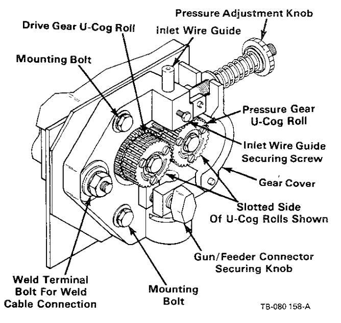
Figure 3 – 5. U-Cog Drive Rolls Installation
3-10. WATER CONNECTIONS (Optional)
CAUTION: OVERHEATING of Gas Metal Arc Welding (GMAW) gun can damage gun.
If using a water-cooled gun and recirculating coolant system, do not make connections from the coolant system to water valve. Instead, make connections directly from the coolant system to gun hoses.
A. Installation Of Water Hoses
When a water-cooled gun is used, route and connect the water hose from the water supply to the water input fitting on the rear of the control box. This fitting has 5/8-18 left-hand threads.
A water supply output fitting is provided on the front of the control box for making the water output connection. Connect water hose fitting from boom to the water output fitting on water valve. This fitting has 5/8-18 left-hand threads.
Connect the water return hose to the adapter at the weld terminal on the drive assembly, and route hose to a proper drain. The solenoid is energized when the POWER switch is placed in the ON position.
B. Electrical Reconnection Of Water Solenoid
WARNING: ELECTRIC SHOCK can kill.
- Do not touch live electrical parts.
- Shut down wire feeder and welding power source and disconnect input power employing 'lockout/tagging procedures' before making internal connections.
Lockout/tagging procedures consist of padlocking line disconnect switch in open position, removing fuses from fuse box, or shutting off and red-tagging circuit breaker or other disconnecting device.
Work on internal parts to be performed only by qualified persons.
The control is shipped connected to supply water when the POWER switch is in the ON position. The water solenoid circuitry can be modified to supply water when the gun trigger is pressed. To make electrical reconnection of water solenoid, proceed as follows:
- 1. Remove control box wrapper.
- Locate terminal strip 1T on bottom panel of control box.
- Move lead 35 from terminal A on terminal strip 1T to terminal B.
- 4. Reinstall wrapper.
- C. Water Connections To Gun
CAUTION: OVERHEATING of Gas Metal Arc Welding (GMAW) gun can damage gun.
If using a water-cooled gun and recirculating coolant system, do not make connections from the coolant system to water valve. Instead, make connections directly from the coolant system to gun hoses.
Connect the gun water input hose to the water output hose at the motor end of the boom. Connect the water return hose from the gun to the adapter at the weld terminal on the drive assembly.
Reducing bushings are provided to accept 5/8-18 lefthand fittings. If the reducing bushings are removed, 7/8-14 left-hand fittings are present.
3-11. WELDING GUN CONNECTIONS TO DRIVE ASSEMBLY
A. Gun Connector To Drive Assembly (Provides Weld Power And Shielding Gas) (Figure 3-4)
IMPORTANT: The outlet guide is provided as part of gun or gun adapter assembly.
1. Loosen gun/feeder connector securing knob.

Figure 3 - 6. Control Box And Boom Connections
IMPORTANT: Wire guides should be installed so that tip of guide is as close to the drive rolls as possible without touching.
- Insert gun/feeder connector, or gun/feeder adapter if required, which includes installed outlet guide, into drive assembly opposite inlet guide.
- 3. Tighten gun/feeder connector securing knob.
B. Gun Trigger (Figure 3-6)
WARNING ELECTRIC SHOCK can kill.
- Do not touch live electrical parts.
- Do not touch electrode wire when gun trigger is pressed.
The welding wire and all metal parts in contact with it carry weld output when the welding power source contactor is energized.
A four-pin plug extends out of the motor end of the boom for connecting the gun trigger plug to the wire feeder. To make connection, proceed as follows: align keyways, insert plug, and rotate threaded collar fully clockwise.
A. Gun Trigger
A trigger receptacle is provided on the front of the control box for making gun trigger control connections. Connect plug from boom to control box TRIGGER receptacle as follows: align keyways, insert plug, and rotate threaded collar fully clockwise.
B. Shielding Gas
A shielding gas output fitting is provided on the front of the control box for making the shielding gas output connection. Connect gas hose fitting from boom to the shielding gas output fitting on gas valve. This fitting has 5/8-18 right-hand threads.
C. Remote Control (If Applicable)
A remote control receptacle is provided on the front of the control box for making remote control connections. Connect plug from remote control to control box REMOTE receptacle as follows: align keyways, insert plug, and rotate threaded collar fully clockwise.
D. Motor Control
A motor control cord extends from the rear of the control box for making motor control connections. Connect plug from boom to plug on motor control cord as follows: align keyways, insert plug, and rotate threaded collar fully clockwise.
3-13. PULLEY ADJUSTMENT (Figure 3-1)
WARNING ELECTRIC SHOCK can kill.
- Do not touch live electrical parts.
- Shut down the welding power source and wire feeder and be sure that they cannot be accidentally energized before adjusting pulley.
Two positions are available for adjusting the boom pulley up or down to provide minimum bend in the wire. For small diameter wires (0.023-5/64 in. or 0.6-2.0 mm), place pully shaft in upper holes. For larger diameter wires (3/32-1/8 in. or 2.4-3.2 mm), place pulley shaft in lower holes. If a pulley adjustment is necessary because of a wire size change, proceed as follows:
- 1. Retract wire and change to new wire size.
- 2. Loosen nuts securing pulley shaft to boom.
- 3. Move shaft to desired position: Upper holes for small diameter wires, lower holes for larger diameter wires.
- 4. Tighten nuts to secure pulley shaft.
- 5. Thread welding wire according to Section 3-18.
WARNING RELEASE OF SPRING PRESSURE WITHOUT BOOM ATTACHED can cause serious personal injury and equipment damage.
- Perform installation exactly as outlined in the following step-by-step instructions.
- Do not remove safety collar until instructed to do so.
- Retain safety collar for future disassembly use.
A safety collar is provided on top of the post to maintain spring pressure and prevent vertical movement during installation. The collar is required whenever the boom is disassembled or relocated. To remove the safety collar, proceed as follows:
- 1. Grasp boom and pull down slightly. The boom should be pulled down only far enough to remove the pressure which is applied to the safety collar.
- 2. Remove the safety collar, and retain for future use.
- 3. The boom should now balance in any position from horizontal to 60 degrees above horizontal. If the boom does not balance properly, proceed to Section 3-15.
3-15. BOOM ADJUSTMENTS (Figure 3-7)
A. Weight Lift Adjustment
WARNING: FALLING BOOM can cause serious personal injury and equipment damage.
Maintain full threads on adjustment rod through the yoke.

TB-072 727-A
Figure 3 - 7. Boom Adjustments
The amount of weight which the boom can retract into the upright position when released can be varied by adjusting the jam nut and adjustment rod located at the base of the boom. If a heavier gun is installed on the end of the boom making it necessary to increase the amount of weight that the boom can lift, loosen the jam nut and rotate the adjustment rod so that the adjustment rod threads into the yoke. When the proper adjustment is obtained, tighten the jam nut against the base of the yoke. If a lighter gun is used, rotate the adjustment rod so that the adjustment rod threads out of the yoke.
B. Locking Knob
By rotating the Locking Knob, located on the side of the swivel plate, in a clockwise direction, the boom may be held in any desired position. Rotating the Locking Knob in a counterclockwise direction will permit the boom to free travel. Changing the position of the Locking Knob to the other threaded holes provided along the side of the swivel plate limits the lift of the boom to 50 degrees or 40 degrees respectively during free travel.
3-16. SUPPLY CONNECTIONS TO CONTROL BOX AND BOOM (Figure 3-6)
A. Shielding Gas
A hose is supplied with the unit for making connections from the shielding gas source to the shielding gas input fitting on the rear of the control box. These fittings have 5/8-18 right-hand threads. To make connections, proceed as follows:
- 1. Connect one end of hose to the shielding gas input fitting on gas valve on rear of control box.
- 2. Route and connect remaining end to regulator on shielding gas supply.
- B. Weld Cable
WARNING: ELECTRIC SHOCK can kill.
- Do not touch live electrical parts.
- Shut down wire feeder and welding power source and disconnect input power employing "lockout/tagging procedures" before making weld cable connections.
Lockout/tagging procedures consist of padlocking line disconnect switch in open position, removing fuses from fuse box, or shutting off and red-tagging circuit breaker or other disconnecting device.
ARCING can damage weld cable terminal.
- Clean weld cable terminal before connecting weld cable if necessary.
- Tighten terminal nut securely.
Loose or dirty connections can cause erratic weld output.
WELD OUTPUT present on grounded wire feeder parts can cause equipment damage.
Do not allow welding cable to touch grounded feeder parts.
If the welding cable lug or exposed welding cable is in contact with any grounded feeder components during
operation, the 115 Volts AC/Contactor Control cord and plugs may be damaged.
A weld cable extends out of the control box end of the boom for making the weld output connection to the welding power source. For Electrode Positive (Reverse Polarity) connections, proceed as follows:
- Route and connect weld cable extending out of the control box end of the boom to the Positive (+) weld output terminal on welding power source (see power source Onwer's Manual). If necessary, use a weld cable extension of adequate size and capacity to reach power source. If cable extension is used, securely bolt and insulate connection point.
- 2. Route and connect another weld cable of adequate size and capacity from the Negative (-) weld output terminal (see power source Owner's Manual) to workpiece.
IMPORTANTE For Electrode Negative/Straight Polarity connections, reverse cable connections to weld output terminals; electrode becomes negative.
C. 115 Volts AC/Contactor Control
WARNING ELECTRIC SHOCK can kill; MOVING PARTS can cause injury.
- Do not touch live electrical parts.
- Keep clear of pinch points.
The control will be electrically hot internally and ready to operate as soon as the 115 volts power plug is connected to the 115 volts ac source and the welding power source is energized.
CAULTONE IMPROPER VOLTAGE APPLIED TO WELDING POWER SOURCE CONTACTOR can damage wire feeder and welding power source.
Be sure welding power source contactor control circuitry requires external supply of 115 vac for contactor control.
This wire feeder supplies 115 volts ac to the welding power source for contactor control.
A 12.5 ft. (3.8 m) 4-conductor cord is provided for 115 volts ac power and contactor control connections between control box and welding power source. To make connections, proceed as follows:
- Connect 115 volts ac/contactor control plug to matching receptacle on rear of control box as follows: align keyways, insert plug, and rotate threaded collar fully clockwise.
- 2. Insert 115 volts ac power plug into 115 volts ac receptacle on welding power source, and rotate plug fully clockwise.
- 3. Insert contactor control plug into contactor control receptacle on welding power source, and rotate plug fully clockwise.
3-17. ADJUSTMENT OF HUB TENSION (Figure 3-2) - Check the hub tension by slowly rotating the wire spool or reel. The wire should unwind freely, but hub tension should be sufficient to keep wire taut and prevent backlash when the wire feed stops. If adjustment is required, loosen or tighten the hex nut on the end of the spindle support shaft accordingly.
3-18. WELDING WIRE THREADING
WARNING ELECTRIC SHOCK can kill; MOVING PARTS can cause injury.
- Do not touch live electrical parts.
- Keep clear of pinch points.
- Do not energize welding power source or wire feeder until instructed to do so.
The welding wire and all metal parts in contact with it are energized while welding.
WELDING WIRE can cause puncture wounds; HOT SURFACES can burn skin.
- Do not press gun trigger until instructed to do so.
- Do not point gun toward any part of the body, any conductive surface, or other personnel when threading welding wire.
-
Allow gun to cool before touching.
- 1. Install the wire (reel-type or spool-type) as instructed in Section 3-6 or 3-7.
- 2. Cut off any portion of the free end of the wire which is not straight. If necessary, straighten wire to remove cast. Be sure that the cut end is free from rough surfaces to permit proper feeding.
- 3. Manually route the wire through the wire guide tube on the side of the boom, over the wire pulley, and to the drive assembly.
- 4. Adjust hub tension according to Section 3-17 if necessary.
- 5. If necessary because of wire size change, adjust boom pulley for minimum wire bend according to Section 3-13.
- 6. Loosen knob on the drive roll pressure adjustment, pivot pressure adjustment free of the cover, and pivot pressure gear assembly away to an open position.
Manually feed wire through the inlet wire guide and intermediate wire guide, if applicable, and on into the outlet wire guide. Feed approximately 4 inches (102 mm) of wire into the outlet wire guide.
IMPORTANE If the U-Cog drive rolls do not align properly when the gear cover is closed, pivot the gear cover away from the drive gear, and roate the pressure gear one tooth (see Section 3-9).
- 8. Pivot the pressure gear assembly closed making sure the teeth on the pressure gear mesh with the teeth on the drive gear. The welding wire must be in the grooves of the drive rolls.
- 9. Pivot the pressure adjustment knob until the washer on the pressure adjustment is seated on top of the gear cover.
- 10. Turn the pressure adjustment knob in a clockwise direction until the drive rolls are tight against the welding wire. Do not overtighten.
- 11. Lay gun cable assembly out flat and straight (no coils in the cable/conduit).
- 12. Energize the welding power source.
- 13. Place the RETRACT/FEED switch in the FEED position.
- 14. Place the wire feeder POWER switch in the ON position.
- 15. Depress the JOG push button (see WARNING block at beginning of this Section). Wire will feed if drive roll pressure is properly adjusted to prevent slippage. If wire slippage is noticed, turn pressure adjustment knob clockwise in 1/4 turn increments until wire slippage stops. If excess pressure is required, check gun contact tube and gun liner for obstructions. Release the JOG push button when welding wire extends approximately one inch (25 mm) out of gun tip.
- 16. Shut down wire feeder and welding power source.
SECTION 4 - OPERATOR CONTROLS =

Figure 4 - 1. Front Panel View
4 - 1. POWER SWITCH (Figure 4-1) - Placing the POWER switch in the ON position applies 115 volts ac to the unit and places it in an operational condition, ready to feed wire and permit shielding gas to flow. Placing the POWER switch in the OFF position shuts down the wire feeder.
IMPORTANT: The welding power source must be energized before the POWER switch can be used to energize the wire feeder.
4 - 2. WIRE SPEED CONTROL (Figure 4-1) – A tenturn WIRE SPEED control provides a means of selecting the rate at which welding wire feeds into the weld. Rotating the WIRE SPEED control clockwise increases the wire feed speed.
4 - 3. JOG PUSH BUTTON (Figure 4-1) – The JOG push button is a momentary-contact switch. When pressed it completes the circuit to the motor without having to press the gun trigger switch. This switch permits jogging of the wire at the setting of the WIRE SPEED control, without energizing the welding circuit or the shielding gas valve.
4 - 4 . PURGE PUSH BUTTON (Figure 4-1) - The PURGE push button is a momentary-contact switch. This switch energizes the gas solenoid and purges the shielding gas line of the gun. The PURGE push button allows the shielding gas regulator to be adjusted without energizing the welding circuit.
4 - 5. RETRACT/FEED SWITCH (Figure 4-1) - The RETRACT/FEED switch determines whether the wire feeds out of the gun or retracts back into the gun when the gun trigger or JOG push button is pressed. The RETRACT position causes the wire to go back into the gun, and the FEED position causes the wire to feed out of the gun. The switch should be in the FEED position for normal operation.
CAUTION: CHANGING SWITCH POSITIONS with motor running will damage motor.
Do not activate the RETRACT/FEED switch while drive motor is running.
4 - 6. START SWITCH (Figure 4-1) - The START switch provides the capability of selecting either a slow wire feed speed for 1/2 second at the beginning of wire feed, or the wire feed speed at the rate set on the WIRE SPEED control. The SLOW position of the START switch provides the 1/2 second of slow wire feed, and the FAST position provides wire feed at the rate set on the WIRE SPEED control.
4 - 7. RESET CIRCUIT BREAKER (Figure 4-1) - The circuit breaker provides protection to the feeder motor. If the motor is overloaded, the breaker would trip and stop all output. If the breaker trips, reset breaker according to Section 6-3.
4 – 8. FUSE (Figure 4-1) – The fuse provides protection from damage due to an internal short or excessive overload. If the fuse opens, the wire feeder will completely shut down. See Section 6-4 for fuse replacement procedure.
4 - 9. REMOTE CONTROL RECEPTACLE AND SWITCH (Figure 4-1) - The remote control receptacle is provided for use with certain optional controls. If a remote control is to be used, make connections as instructed in Section 3-12, and place the Remote Control switch in the REMOTE position. If a remote control is not to be used, place the Remote Control switch in the STANDARD position.
4-10. BURNBACK CONTROL (Optional) - The burnback circuitry in this control keeps the welding wire from sticking to the workpiece after the gun trigger is
SECTION 5 - SEQUENCE OF OPERATION
5 - 1. GAS METAL ARC WELDING (GMAW)
WARNINGE ELECTRIC SHOCK can kill; MOVING PARTS can cause serious injury; IMPROPER AIR FLOW AND EXPOSURE TO ENVIRONMENT can damage internal parts.
- Do not touch live electrical parts.
- Keep clear of pinch points.
- Keep all covers and panels in place while operating.
Warranty is void if the wire feeder is operated with any portion of the outer enclosure removed.
ARC RAYS, SPARKS, AND HOT SURFACES can burn eyes and skin; NOISE can damage hearing.
• Wear correct eye, ear, and body protection.
FUMES AND GASES can seriously harm your health.
- Ventilate to keep from breathing fumes and gases.
- If ventilation is inadequate, use approved breathing apparatus.
WELDING WIRE can cause puncture wounds.
Do not point gun toward any part of the body, any conductive surface, or other personnel.
HOT METAL, SPATTER, AND SLAG can cause fire and burns.
- Watch for fire.
- Have a fire extinguisher nearby and know how to use it.
- Allow work and equipment to cool before handling.
MAGNETIC FIELDS FROM HIGH CURRENTS can affect pacemaker operation.
Wearers should consult with their doctor before going near arc welding, gouging, or spot welding operations.
See Section 1 - Safety Rules For Operation Of Arc Welding Power Source for basic welding safety information.
- 1. Make all connections and thread welding wire as instructed in Section 3.
- 2. Place Remote Control switch on both power source and wire feeder in desired position (see Section 4-9).
released. The burnback capability in this wire feeder keeps weld output present on the welding wire from 0 to 15 cycles after the wire has stopped feeding, depending on the setting of the BURNBACK control. This delay action permits the welding wire to burn back to a point where it neither sticks to the workpiece nor the contact tube. If the welding wire sticks to contact tube, rotate the BURNBACK control counterclockwise. If the welding wire sticks to the workpiece, rotate the BURN-BACK control clockwise.
- 3. Place the START switch in the desired position (see Section 4-6).
- 4. Place the RETRACT/FEED switch in the FEED position.
- 5. Rotate the WIRE SPEED control to the desired setting (see Section 4-2).
- 6. Turn on the shielding at the source.
- 7. Energize the welding power source.
- 8. Place the POWER switch in the ON position.
- 9. Depress the PURGE push button for one minute.
- 10. Hold the tip of the gun approximately 1/2 inch (13 mm) from the workpiece.
WARNING ELECTRIC SHOCK can kill.
- Do not touch live electrical parts.
- Do not touch welding wire or any metal part in contact with it while welding.
The welding wire and all metal parts in contact with it carry weld output when the welding power source contactor is energized.
Press the gun trigger. Gas will flow and wire will feed if drive roll pressure is properly adjusted to prevent slippage. If wire slippage is noticed, adjust drive roll pressure according to Section 3-18.
5 - 2. SHUTTING DOWN
- 1. Shut down wire feeder and welding power source.
- 2. Turn off shielding gas at the source.
- 3. Turn off all associated equipment.
MARNINGE HIGH CONCENTRATION OF SHIELDING GAS can harm health or kill.
Shut off gas supply when not in use.
IMPORTANT: Every six months inspect the labels on this unit for legibility. All precautionary labels must be maintained in a clearly readable state and replaced when necessary. See the Parts List for part number of precautionary labels.
6 - 1. INSPECTION AND UPKEEP - Usage and shop conditions will determine the frequency and type of maintenance. At minimum, inspect equipment every three months as follows:
WARNINGE ELECTRIC SHOCK can kill; WELDING WIRE can cause puncture wounds; HOT SURFACES can burn skin.
- Do not touch live electrical parts.
- Shut down wire feeder and welding power source and disconnect input power employing "lockout/tagging procedures" before inspecting, maintaining, or servicing.
Lockout/tagging procedures consist of padlocking line disconnect switch in open position, removing fuses from fuse box, or shutting off and red-tagging circuit breaker or other disconnecting device.
- Allow gun and unit to cool before touching.
-
Do not press gun trigger while performing maintenance on gun.
- 1. Inspect gun for broken areas, cracks, and loose parts: tighten, repair, and replace as required.
- 2. Carefully remove any weld spatter or foreign matter which may accumulate around the nozzle orifice. Use a hardwood stick, never a metal tool.
- 3. Repair or replace, as required, all hose and cable; give particular attention to frayed and cracked insulation and areas where it enters equipment.
- 4. Remove grease and grime from components; moisture from electrical parts and cable.
CAUTION: FLYING DIRT AND METAL PAR-TICLES can injure personnel and damage equipment.
-
Point gun liner only in a safe direction away from personnel and equipment when cleaning with compressed air.
- 5. Blow out the gun wire guide liner with compressed air when changing wire. This will remove any metal chips and dirt that may have accumulated.
6 - 2. CLEANING OF DRIVE ROLLS
IMPORTANCE Failure to properly maintain the drive rolls can result in a buildup of wire particles which will decrease the efficiency of the wire feeding operation.
Every time welding wire is installed or changed, inspect the wire groove on the drive rolls for a buildup of wire particles. If necessary, clean the drive rolls as follows:
WARNING: ELECTRIC SHOCK can kill.
- Do not touch live electrical parts.
- Keep clear of pinch points.
- Shut down wire feeder and welding power source and disconnect input power employing "lockout/tagging procedures" before inspecting, maintaining, or servicing.
Lockout/tagging procedures consist of padlocking line disconnect switch in open position, removing fuses from fuse box, or shutting off and red-tagging circuit breaker or other disconnecting device.
1. Remove the three drive roll securing screws from each drive roll, and remove drive rolls (see Section 3-9).
WARNING: HIGH ROTATIONAL SPEED may cause damage to drive rolls and injure personnel.
-
Do not allow drive rolls to rotate at high speed if compressed air is used for cleaning the drive roll assembly.
- 2. Using a wire brush, remove the buildup of wire particles in the wire grooves.
- 3. Reinstall drive rolls according to Section 3-9.
- 4. Resume operation.
6 - 3. MOTOR OVERLOAD BREAKER (Figure 4-1)
WARNING ELECTRIC SHOCK can kill.
- Do not touch live electrical parts.
- Shut down wire feeder and welding power source and disconnect input power employing "lockout/tagging procedures" before inspecting, maintaining, or servicing.
Lockout/tagging procedures consist of padlocking line disconnect switch in open position, removing fuses from fuse box, or shutting off and red-tagging circuit breaker or other disconnecting device.
The drive motor is protected from damage due to overload by circuit breaker CB1. CB1 is an automatictrip type breaker. If CB1 should open, the wire feeder would immediately stop the weld. When the circuit breaker is in (ON position), the circuit breaker is functional. When the button is out (OFF position), the breaker is open.
Should a motor overload occur and trip CB1, proceed as follows:
- 1. Check for jammed wire or clogged gun liner, and correct problem. If motor overload happens often, repair or replace the motor or liner.
- 2. Check for binding drive gear or misaligned drive rolls, and correct problem.
- 3. Reset circuit breaker (depress button); it may be necessary to allow a cooling period before the breaker can be reset.
- 4. Resume operation.
6 - 4. OVERLOAD PROTECTION (Figure 4-1)
WARNING : ELECTRIC SHOCK can kill.
- Do not touch live electrical parts.
- Shut down wire feeder and welding power source and disconnect input power employing "lockout/tagging procedures" before inspecting, maintaining, or servicing.
Lockout/tagging procedures consist of padlocking line disconnect switch in open position, removing fuses from fuse box, or shutting off and red-tagging circuit breaker or other disconnecting device.
The wire feeder is protected from damage due to an internal short or excessive overload by fuse F1. Fuse F1 is located on the front panel. If fuse F1 should open, the wire feeder would completely shut down. To replace the fuse, proceed as follows:
CAUTION : IMPROPER FUSES can damage unit.
-
Be sure replacement fuses are same size, type, and rating (see Parts List).
- 1. Depress and rotate fuse holder cover counterclockwise.
- 2. Pull out fuse with cover when fuse holder cover is free.
- 3. Insert new fuse into fuse holder cover.
- 4. Install fuse with fuse holder cover back into unit.
- 5. Depress and rotate fuse holder cover clockwise until cover is secure.
6 - 5. BRUSH INSPECTION AND REPLACEMENT (Figures 6-1 And 6-2)
WARNING: ELECTRIC SHOCK can kill.
- Do not touch live electrical parts.
- Shut down wire feeder and welding power source and disconnect input power employing "lockout/tagging procedures" before inspecting, maintaining, or servicing.
Lockout/tagging procedures consist of padlocking line disconnect switch in open position, removing fuses from fuse box, or shutting off and red-tagging circuit breaker or other disconnecting device.
CAUTIONE DISASSEMBLY OF MOTOR FIELD MAGNETS can result in personal injury and equipment damage.
• Limit drive motor repairs to brush replacement. The field magnets are very strong. If disassembly is attempted, injury to fingers and hands may result from
the rotor being drawn back into the motor. The field magnets are matched sets and operation may be affected if the magnets are tampered with. Warranty is void if the motor is tampered with.
Work on internal parts to be performed only by qualified persons.
- 1. Open brush cap by sliding screwdriver under catch and lifting. Remove brush cap.
- 2. Grasp spring retaining bracket with long-nose pliers.
- 3. Push spring retaining bracket in slightly and move towards brush. This should release the spring assembly and it can be removed.

TA-046 226
Figure 6 – 1. View Of Spring Assembly And Brush When Brush Cap Is Opened
- 4. Pull brush out using brush pigtail.
- 5. If the brushes are less than 1/4 in. (6.4 mm) long, replacement is necessary. Disconnect brush pigtail from brush box tab and remove brush.
- 6. Connect new brush pigtail to brush box tab.
- 7. Route pigtail through slot in brush box. Be sure that the pigtail will not come into contact with a metal surface.
- 8. Insert brush into brush box. Be sure that the low end of the bevel on the top of the brush is towards the spring.
- Using long-nose pliers, insert spring assembly beside brush sliding spring retaining bracket along brush box wall. The spring retaining bracket hooks on the brush box wall as illustrated in Figure 6-2.
- 10. If spring retaining bracket is in place, it will be against the brush box wall when pliers are released.
- 11. Be sure that the spring is in proper position as shown in Figures 6-1 and 6-2.
- 12. Replace and latch the brush cap.
- 13. Reconnect power to all equipment and resume operation.

assembly hooks here.
TA-046 226
Figure 6 - 2. View Of Spring Assembly And Brush From Armature End Of Motor
6 - 6. CIRCUIT BOARD REPLACEMENT PRO-CEDURE (Figure 6-3)
WARNING : ELECTRIC SHOCK can kill.
- Do not touch live electrical parts.
- Safely discharge capacitor C1 before replacing circuit board.
- Shut down wire feeder and welding power source and disconnect input power employing "lockout/tagging procedures" before inspecting, maintaining, or servicing.
Lockout/tagging procedures consist of padlocking line disconnect switch in open position, removing fuses from fuse box, or shutting off and red-tagging circuit breaker or other disconnecting device.
CAUTION : ELECTROSTATIC DISCHARGE (ESD) can damage circuit board components.
- Put on properly grounded wrist strap BEFORE handling circuit boards.
- Transport all static sensitive components in proper static-shielding carriers or packages.
- Perform work only at a static-safe work area.
Work on internal parts to be performed only by qualified persons.
- 1. Remove wrapper.
- 2. Remove hardware securing circuit board to inside rear panel.
- 3. Remove circuit board from edge connector RC5, and set circuit board aside.
- Install connector edge of new circuit board into RC5, and secure with hardware removed in Step 2.
- 5. Reinstall wrapper, and resume operation.

Figure 6 - 3. Circuit Board And Component Locations
6 - 7. TROUBLESHOOTING CHART
WARNING ELECTRIC SHOCK can kill.
- Do not touch live electrical parts.
- Shut down wire feeder and welding power source and disconnect input power employing "lockout/tagging procedures" before inspecting or servicina.
Lockout/tagging procedures consist of padlocking line disconnect switch in open position, removing fuses from fuse box, or shutting off and red-tagging circuit breaker or other disconnecting device.
MOVING PARTS can cause serious injury. Keep clear of pinch points.
- HOT SURFACES can cause severe burns. • Allow cooling period before servicing.
Troubleshooting to be performed only by qualified persons.
It is assumed that the unit was properly installed according to Section 3 of this manual, the operator is familiar with the function of controls, the wire feeder was working properly, and that the trouble is not related to the welding process. The following chart is designed to diagnose and provide remedies for some of the troubles that may develop in this wire feeder.
Use this chart in conjunction with the circuit diagram while performing troubleshooting procedures. If the trouble is not remedied after performing these procedures, the nearest Factory Authorized Service Station should be contacted. In all cases of equipment malfunction, the manufacturer's recommendations should be strictly followed.
| TROUBLE | PROBABLE CAUSE | REMEDY |
|---|---|---|
| Pressing gun trigger will not | POWER switch S1. | Place S1 in the ON position. |
|
trode wire is not energized,
and shielding gas does not |
Check S1 for continuity, and replace S1 if necessary. | |
|
115 volts ac/contactor con-
trol plug PLG1 is not secure in receptacle RC1 on wire feeder, or plug PLG8 is not secure in 115 volts ac receptacle on welding power source. |
Secure PLG1 in receptacle RC1, or secure PLG8 in receptacle on power source (see Section 3-16). | |
|
Plug from gun trigger con-
trol cable is not secure in plug PLG9, or plug PLG2 is not secure in TRIGGER receptacle RC2. |
Secure PLG9 and PLG2 (see Sections 3-11 and 3-12). | |
| Gun trigger or gun trigger cord. | Check trigger and cord for continuity and replace if necessary. | |
| Circuit breaker CB1. | Reset CB1 according to Section 6-3. | |
| Fuse F1. | Check and replace F1 according to Section 6-4. | |
| Relay CR1 or CR2. | Check and replace CR1 and CR2 if necessary. | |
| Welding power source. |
See TROUBLESHOOTING Section in welding
power source Owner's Manual. |
|
|
Wire feeds, shielding gas
flows, but electrode wire is not energized. |
Contactor control plug
PLG3 is not secure in con- tactor receptacle on welding power source. |
Secure PLG3 in receptacle. |
| Welding power source. | See TROUBLESHOOTING Section in welding power source Owner's Manual. |
| Wire feeds erratically. | Obstruction in gun contact tube or liner. | Clear obstruction in gun contact tube or gun liner. |
| Incorrect pressure on drive rolls. | Adjust drive roll pressure according to Section 3-18. | |
| Incorrect size of drive roll (does not match wire). | Change to proper size drive roll (see Section 3-8). | |
| Worn drive roll. | Replace drive roll (see Section 3-8). | |
| Dirt in drive roll or incorrect hub tension. | Clean drive roll as instructed in Section 6-2; check hub tension according to Section 3-17. | |
| Motor runs slowly. | Excessive motor load or binding drive gear. | Reduce load or readjust drive gear (see Section 3-9). |
| Low line voltage. | Correct low line voltage. | |
|
Motor is completely in-
operative, or runs at full speed. |
Circuit board. | Replace circuit board according to Section 6-6. |

Circuit Diagram No. B-110 642-A

January 1987 FORM: OM-1516F
Effective With Serial No. JG070373

PARTS LIST

| Item Dia. Part Description Id Figure A Main Assembly Image: Comparison of the state of the | Qua | intity | |||||
|---|---|---|---|---|---|---|---|
| No. Description 12 16 Figure A Main Assembly 1 12 16 1 0.99 522 CABLE, control - interconnecting (consisting of) 1 1 2 PLG3 039 635 CONNECTOR BODY, twistock approved 2P3W 150 mp 257 volts 1 1 4 604 571 CABLE, No. 18 4/c (order by ft.) 13 ft 5 079 531 CLAMP, cable 29/c (dia) 1 7 049 455 CABLE, No. 18 2/c (order by ft.) 2ft 8 048 274 HOUS ASSEMBLY, gas (consisting of) 1 1 9 065 1297 ADAPTER. 10 010 603 FITTING, hose - brass bartod nipple 1/4 TBG 2 2 1 11 039 063 288 RECETRACE WS/OKETS, free hanging (consisting of) 14 048 018 CABLE, House Barce Consisting of) 14 048 018 CABLE, | Itom | Dia | Part | Mo | odel | ||
| Figure A Main Assembly 1 099 522 CABLE, control - interconnecting (consisting of). 1 1 3 PLG3 038 635 CONNECTOR BODY, twistlock 2P2W 20 emp 250 volts. 1 1 4 66 4571 CABLE, No. 18 4/c (order by ft.) 13 ft 5 078 831 CLAMP, coble 29/64 dia. 1 7 049 682 HOLSING PLUG 6 SOCKETS (consisting of) 1 7 049 682 HOLE, Nam 12 /c (order by ft.) 21 ft 2 ft 2 ft 9 061 827 HTING, hose- brass harted night 1/4 TBG. 2 z 2 lt 0 661 12 .FTITING, hose- brass harted night 1/4 TBG. 2 z 2 lt 10 ft 10 lt 11 lt 10 010 6032 FTITING, hose- brass fund A/ft 15 lb x 23/32. 2 z 2 lt 2 ft 2 lt 2 ft 2 lt 2 lt 10 ft 11 lt 10 ft 2 lt 2 lt | No. | Mkgs. | No. | Description | 12 | 16 | |
Figure A
Main Assembly
1
0.99 522 CABLE_control - interconnecting (consisting of),
1
1
2
PLG3
0.39 635
CONNECTOR 60DY, twistlock 2P2W 20 amg 250 volts.
1
1
4
0.39 635
CONNECTOR 60DY, twistlock 2P2W 20 amg 250 volts.
1
1
4
0.46 71
CABLE, No. 18 4/(corder by ft.)
13 ft
13 ft
5
0.79 531
CLAMP, cable 29/64 dia
1
1
7
0.44 824
HOUSING PLUG 6F SOCKETS (consisting of)
21t
21t
7
0.44 824
FERMINAL (emale
21t
8
0.48 824
HOUSING PLUG 6F SOCKETS (consisting of)
21t
|
|
|
_
|
|
|
|
|
|
| 1 099 522 CABLE, control - interconnecting (consisting of). 1 1 2 PLG3 038 635 CONNECTOR BODY, twistock ZP2W 20 amp 250 volts. 1 1 4 604 571 CABLE, No. 18 4/c (order by ft.) 13 ft 13ft 1 4 604 571 CABLE, No. 18 4/c (order by ft.) 13 ft 13ft 1 6 PLG1 048 284 HOUSING FLUG & SOCKETS (consisting of) 1 1 7 0448 485 CABLE, No. 18 2/c (order by ft.) 2ft 1 7 0448 485 CABLE, No. 18 2/c (order by ft.) 2ft 10 010 603 FITTING, hose- brass barbed nipple 1/4 TBG. 2 2 1 10 010 603 FITTING, hose- brass forue 0.475 Ib 2 23/32. 2 2 10 048 012 CABLE, trigger 16 ft consisting of) 11 046 012 CABLE, trigger 16 ft consisting of) 10 073 236 CABLE, trigger 20 ft c | Ει | gure A | Main Assembly | ||||
| 2 PLG3 039 655 CONNECTOR BODY, Mistlock 2P2W 20 amp 250 volts 1 1 4 604 571 CABLE, No. 18 4/c (order by ft.) 13 ft 13ft 5 079 531 CLAMP, cable 26/64 dia 1 1 7 049 455 CABLE, No. 18 2/c (order by ft.) 2ft 2ft 8 048 837 HOSE ASSEMBLY, gas (consisting of) 1 1 9 051 227 ADAPTER 10 016 003 FITTING, hose - brass barbed nipple 1/4 TBG. 2 11 016 006 FITTING, hose - brass hord 751 Dx 23/32 2 11 016 006 FITTING, hose - brass hord 751 Dx 23/32 2 13 603 106 HOSE, No. 1 (order by ft) 10ft 14 048 012 CABLE, tringer 16 (consisting of) 14 048 013 CABLE, tringer 16 (consisting of) 15 PLG3 083 28 RECEPTACLE W/SOCKETS, free hanging (consisting of) 16 079 531< | 1 | 099 522 | CABLE, control - interconnecting (consisting of) | 1 | 1 | ||
| 3 PLG8 039 687 .CAP, twistlock - grounded 2P3W 15 amp 277 volts. 1 1 4 604 571 .CAMP, cable 29/64 dia 1 6 PLG1 048 284 HOUSINO FLUG 65 QCKETS (consisting of) 1 7 049 455 CABLE, No. 18 2/c (order by ft.) 2ft 8 048 837 HOSE ASSEMBLY, gas (consisting of) 1 9 051 297 ADAPTER 10 010 606 FITTING, hose- brass branch of APS 10 x 23/32 2 11 010 606 FITTING, hose- brass fortule 0.475 10 x 23/32 2 12 056 112 FITTING, hose- brass fortule 0.475 10 x 23/32 2 13 603 106 HOSE, NO. 1 (order by ft.) 10ft 14 048 012 CABLE, itdggs 16 ft (consisting of) 15 PLG3 03 082 RECEPTACLE W/S OKETS, free hanging (consisting of) 16 079 353 | 2 | PLG3 | 039 635 | . CONNECTOR BODY, twistlock 2P2W 20 amp 250 volts | 1 | 1 | |
| 4 604 571 CABLE, No. 18 å/c (order by ft.) 13 1 5 079 531 CLAMP, cable 29/64 dia 1 1 7 049 455 CABLE, No. 18 2/c (order by ft.) 2ft 2ft 8 048 837 HOSE ASSEMBLY, gas (consisting of) 1 1 9 051 297 ADAPTER 10 016 003 FITTING, hose - brass barbed nipple 1/4 TBG. 2 2 11 016 006 FITTING, hose - brass formal 0.475 Ib x 23/32 2 2 12 056 112 FITTING, hose - brass formal 0.475 Ib x 23/32 2 2 13 603 106 HOSE, No. 1 (order by ft) 10ft 14 049 012 CABLE, trigger 16 ft (consisting of) 14 048 018 28.8 RECEPTACLE W/SOCKETS, free hanging (consisting of) 15 PLG9 080 328.8 RECEPTACLE W/SOCKETS, free hanging (consisting of) 16 079 531 CLAMP, cable 29/64 2 16 079 537 CLAMP, cable 29/16 | 3 | PLG8 | 039 687 | . CAP, twistlock - grounded 2P3W 15 amp 277 volts | 1 | 1 | |
| 5 079 531 CLAMP, cable 22/64 dia 1 1 6 PLG1 048 284 HOUSING PLUG & SOCKETS (consisting of) 1 1 7 049 455 CABLE, No. 18 2/c (corder by ft.) 2ft 8 048 837 HOSE ASSEMBLY, gas (consisting of) 1 9 051 207 ADAPTER 10 010 603 FITTING, hose- brass brated nipple 1/4 TBG 2 2 11 010 606 FITTING, hose- brass fortule 0,475 10 x 23/32 2 2 13 603 106 HOSE, No. 1 (order by ft.) 10ft 10ft 14 049 012 CABLE, indger 16 ft consisting of) 14 048 013 CABLE, indger 16 ft consisting of) 1 079 531 CLAMP, cable 29/64 2 1 16 079 204 HOSE, gas (consisting of) 19 073 525 TERMINAL, fremale 4 | 4 | 604 571 | . CABLE, No. 18 4/c (order by ft.) | 13 ft | 13ft | ||
| 6 PLG1 048 284 HOUSING PLUG & SOCKETS (consisting of) 1 1 7 049 455 .CABLE, No. 18 2/c (order by ft.) | 5 | 079 531 | . CLAMP, cable 29/64 dia | 1 | 1 | ||
| 079 634 TERMINAL, female 1 7 049 455 CABLE, No. 18 2/c (order by ft.) | 6 | PLG1 | 048 284 | . HOUSING PLUG & SOCKETS (consisting of) | 1 | 1 | |
| 7 049 455 .CABLE, No. 1s 2/c (order by ft.) | 079 534 | TERMINAL, female | 1 | 1 | |||
| 8 048 837 HOSE ASSEMBLY, gas (consisting of) 1 1 9 051 297 ADAPTER 10 010 603 FITTING, hose - brass bruts //b.18 RH 2 2 11 010 606 FITTING, hose - brass bruts //b.18 RH 2 2 13 603 106 HOSE, No. 1 (order by ft) 10ft 10ft 14 049 012 CABLE, trigger 16 ft (consisting of) 14 048 018 CABLE, trigger 20 ft (consisting of) 15 PLG9 803 228 RECEPTACLE W/SOCKETS, free hanging (consisting of) 16 079 534 .TERMINAL, female 4 17 605 156 CABLE, No. 18 4 /c (order by ft.) 16ft 20ft 18 PLG2 079 878 HOUSKP (PLG) & PINS (consisting of) 19 079 525 .TERMINAL, male 1 20 079 204 HOSE, gas (consisting of) 1 | 7 | 049 455 | . CABLE, No. 18 2/c (order by ft.) | 2ft | 2ft | ||
| 9 061 297 ADAPTER 10 010 603 FITTING, hose - brass barbed nipple 1/4 TBG. 2 2 11 010 606 FITTING, hose - brass ferrule 0.475 ID x 23/32 2 2 13 603 106 HOSE, No. 1 forder by ft) 10ft 14 048 012 CABLE, trigger 16 ft (consisting of) 14 048 013 CABLE, trigger 20 ft (consisting of) 15 PLG9 080 328 .RECEPTACLE W/SOCKETS, free hanging (consisting of) 19 079 533 .CLAMP, cable 29/64 2 16 079 353 .TERMINAL, female 4 4 20 079 202 10SE, gas (consisting of) 19 079 3202 10SE, gas (consisting of) 1 1 21 056 518 .FITTING, hose- brass barbed nipple 3/16 TBG. 1 1 22 010 606 .FITTING, hose- brass barbed nipple 3/16 TBG. 1 1 | 8 | 048 837 | HOSE ASSEMBLY, gas (consisting of) | 1 | 1 | ||
| 10 010 603 FITTING, hose - brass barbed nipple 1/4 TBG 2 2 11 010 606 FITTING, hose - brass barb 5/8-18 RH 2 2 13 603 106 HOSE, No. 1 (order by ft) 10ft 10ft 14 048 012 CABLE, trigger 16 ft (consisting of) 14 048 018 CABLE, trigger 16 ft (consisting of) 15 PLG9 080 328 RECEPTACLE W/SOCKETS, free hanging (consisting of) 16 079 531 CLAMP, cable 29/64 2 17 R65 156 CABLE, No. 18 4 /c (order by ft.) 16ft 20ft 1 19 079 535 TERMINAL, male. 4 20 079 202 HOSE; gas (consisting of) 1 21 066 6651 FITTING, hose - brass barbed nipple 3/16 TBG 1 1 21 066 6613 FITTING, hose - brass barbed nipple 3/16 TBG 1 1 22 010 606 FITTING, hose - brass | 9 | 051 297 | ADAPTER | 1 | 1 | ||
| 11 010 606 FITTING, hose brass ferrule 0.475 ID x 23/32. 2 2 12 056 112 FITTING, hose brass ferrule 0.475 ID x 23/32. 2 2 13 603 106 HOSE, No. 1 (order by ft) 10ft 10ft 14 049 012 CABLE, trigger 16 ft (consisting of) 14 049 012 CABLE, trigger 20 ft (consisting of) 15 PLG9 080 328 .RECEPTACLE W/SOCKETS, free hanging (consisting of) 16 079 531 .CLAMP, cable 29/64 2 17 605 156 .CABLE, No. 18 4 /c (order by ft.) 16ft 20ft 19 079 525 .TERMINAL, male. 4 20 079 202 HOSE, gas (consisting of) 1 21 056 851 .FITTING, hose brass barbed nipple 3/16 TBG 1 1 22 010 606 .FITTING, hose brass barbed nipple 3/16 TBG 1 1 23 056 108 .FITTING, hose brass barbed nipple 3/16 TBG 1 1 24 604 550 | 10 | 010 603 | . FITTING, hose - brass barbed nipple 1/4 TBG | 2 | 2 | ||
12
056 112
FITTING, hose-brass ferrule 0.475 ID x 23/32
2
13
603 106
HOSE, No. 1 (drote by ft).
10ft
14
048 618
CABLE, trigger 16 ft (consisting of).
1
14
048 618
CABLE, trigger 10 ft (consisting of).
1
15
PLG9
808 328
RECEPTACLE W/SOCKETS, free hanging (consisting of).
1
16
079 534
. TERMINAL, female
4
4
16
079 535
. CLAMP, cable 29/64
2
2
17
605 156
CABLE, NO. 18 4/a (corder by ft.)
16ft
20ft
19
079 878
. HOUSINC PLUG & PINS (consisting of)
19
079 202
HOSE, gas (consisting of)
1
1
20
079 204
HOSE, sic consisting of)
1
1
21
056 651
FITTING, hose- brass barbed nipple 3/16 TBG
1
1
22
016 606
FITTING, hose- brass not 5/8-16
1
22
016 606
FITTING, hose- brass not 5/8-16
1
24
604 550
|
|
11
|
|
010 606
|
. FITTING, hose - brass nut 5/8-18 RH
|
2
|
2
|
|
| 13 603 106 .HOSE No. 1 (order by ft) 10ft 10ft 14 049 012 CABLE, trigger 16 ft (consisting of) 1 15 PLG9 080 328 .RECEPTACLE W/SOCKETS, free hanging (consisting of) 15 PLG9 080 328 .TERMINAL, female 4 4 16 079 534 .TERMINAL, female 4 4 17 605 156 CABLE, No. 18 4/c (order by ft.) 16ft 20ft 18 PLG2 079 878 .HOUSING PLUG & PINS (consisting of) 1 1 20 079 204 HOSE, gas (consisting of) 1 21 056 651 .TERMINAL, male. 4 4 1 22 010 606 .FITTING, hose - brass barbed nipple 3/16 TBG. 1 23 056 108 .FITTING, hose - brass farrule 0.425 ID x 23/32. 1 24 604 550 HOSE, No. 1 x 3/16 ID (order by ft.) .1 1 25 072 088 CONTROL BOX (Fig B Pg 4) 1 | 12 | 056 112 | FITTING, hose - brass ferrule 0.475 ID x 23/32 | 2 | 2 | ||
| 14 049 012 CABLE, trigger 16 ft (consisting of) 1 14 048 018 CABLE, trigger 20 ft (consisting of) 1 15 PLG9 080 328 RECEPTACE V/SOCKETS, free hanging (consisting of) 1 16 079 534 . TERMINAL, female 4 4 16 079 535 . CLAMP, cable 29/64 2 2 17 605 156 . CABLE, No. 18 4/c (order by ft.) 16ft 20ft 18 PLG2 079 878 . HOUSING PLUG E PINS (consisting of) 1 1 20 079 202 HOSE, gas (consisting of) 1 21 056 6851 . FITTING, hose - brass barbed nipple 3/16 TBG 1 22 010 606 . FITTING, hose - brass fruite 0.425 ID x:23/32 1 23 056 108 . FITTING, hose - brass fruite 0.425 ID x:23/32 1 24 604 550 . HOSE, No. 1 x 3/16 ID (order by ft.) . 17ft 21ft 25 072 102 CABLE, motor 21 ft (consisting of) 1 26 072 102 | 13 | 603 106 | HOSE No. 1 (order by ft) | 10ft | 10ft | ||
| 14 048 618 CABLE, trigger 20 ft (consisting of) 1 15 PLG9 080 328 RECEPTACLE W/SOCKETS, free hanging (consisting of) 16 079 531 .CLAMP, cable 29/64 2 2 17 606 156 CABLE, No. 18 4/c (order by ft.) 16ft 20ft 18 PLG2 073 878 HOUSING PLUG & PINS (consisting of) 19 079 535 .TERMINAL, male. 4 4 20 079 204 HOSE, gas (consisting of) 1 1 21 066 815 .FITTING, hose- brass barbed nipple 3/16 TBG 1 1 22 010 606 .FITTING, hose- brass barbed nipple 3/16 TBG 1 1 23 066 108 .FITTING, hose- brass barbed nipple 3/16 TBG 1 1 24 604 550 HOSE, not 1 x 3/16 1D (order by ft.) 17ft 1 26 072 102 CABLE, motor 17 ft (consisting of) 1 1 26 072 102 CABLE, motor 21 ft (consisting of) 1 1 26 072 102 CABLE, mover 30 ft (consisting of) 1 | 14 | 049 012 | CABLE trigger 16 ft (consisting of) | 1 | 1010 | ||
| 15 PLG9 080 328 RECEPTACLE W/SOCKETS, free hanging (consisting of) 1 1 079 534 TERMINAL, female 4 4 16 079 531 CLAMP, cable 29/64 2 2 17 605 156 CABLE, No. 18 4/c (order by ft.) 16ft 20ft 19 079 535 TERMINAL, male 4 4 20 079 202 HOSE, gas (consisting of) 1 1 21 056 851 FITTING, hose - brass barbed nipple 3/16 TBG 1 1 22 010 606 FITTING, hose - brass forule 0.425 ID x 23/32 1 1 23 056 108 FITTING, hose - brass forule 0.425 ID x 23/32 1 1 24 604 550 | 14 | 048 618 | CABLE trigger 20 ft (consisting of) | 1 | |||
079 534
TERMINAL, female
4
4
16
079 531
CLAMP, cable 29/64
2
2
17
605 156
CABLE, No. 18 4/c (order by ft.)
16ft 20ft
18
PLG2
079 535
TERMINAL, male.
4
4
20
079 202
HOSE, gas (consisting of)
1
1
20
079 204
HOSE, gas (consisting of)
1
1
20
079 204
HOSE, gas (consisting of)
1
1
21
056 851
FITTING, hose -brass barbed nipple 3/16 TBG.
1
1
22
010 606
FITTING, hose -brass ferule 0.425 ID x23/32
1
1
23
056 108
TERMINAL, fill D (order by ft.)
17ft 21ft
24
604 550
HOSE, No. 1 x 3/16 ID (order by ft.)
17ft 21ft
25
072 088
CONTROL BOX (Fig B Pg 4)
1
1
26
072 103
CABLE, motor 21 ft (consisting of)
1
1
27
PLG7(M)
048 306
.RECEPTACLE & PINS (consisting of)
1
1
27
PLG7(M)
|
|
15
|
PLG9
|
080 328
|
BECEPTACLE W/SOCKETS_free hanging (consisting of)
|
1
|
1
|
|
| 16 079 531 .CLAMP, cable 29/64 2 2 17 605 156 .CABLE, No. 18 4/c (order by ft.) 16ft 20ft 18 PLG2 079 535 .TERMINAL, male. 4 4 20 079 202 HOSE, gas (consisting of) 1 1 20 079 204 HOSE, gas (consisting of) 1 1 21 056 651 .FITTING, hose - brass barbed nipple 3/16 TBG. 1 1 22 010 606 .FITTING, hose - brass nut 5/8-16 1 1 23 056 108 .FITTING, hose - brass nut 5/8-16 1 1 24 604 550 .HOSE, No. 1 x 3/16 ID (order by ft.) 17ft 21ft 25 072 088 CONTROL BOX (Fig Br 94) 1 26 072 103 CABLE, motor 17 ft (consisting of) 1 26 072 103 CABLE, motor 17 ft (consisting of) 1 26 072 103 CABLE, No. 18 3/c (order by ft.) 1 26 072 103 CABLE, No. 18 3/c (order by ft.) 1 | . 200 | 079 534 | 4 | 4 | |||
| 17 605 156 .CABLE, No. 18 4/c (order by ft.) 16ft 20ft 18 PLG2 079 878 .HOUSING PLUG & PINS (consisting of) 19 079 525 .TERMINAL, male 4 4 20 079 202 HOSE, gas (consisting of) 1 1 20 079 204 HOSE, gas (consisting of) 1 1 20 079 204 HOSE, gas (consisting of) 1 1 21 056 165 .FITTING, hose - brass barbed nipple 3/16 TBG 1 1 22 010 606 .FITTING, hose - brass nut 5/8-16 1 1 23 056 108 .FITTING, hose - brass nut 5/8-16 1 1 24 604 550 .HOSE, No. 1 x 3/16 ID (order by ft.) .17ft 21ft 25 072 088 CONTROL BOX (Fig B Pg 4) 1 26 072 102 CABLE, motor 21 ft (consisting of) 1 26 072 102 CABLE, power 21 ft (consisting of) 1 27 PLG7(M) 048 306 .RECEPTACLE & PINS (conder by ft.) | 16 | 079 531 | CLAMP cable 29/64 | 2 | 2 | ||
| 18 PLG2 079 878 . HOUSING PLUG & PINS (consisting of) 19 079 535 . TERMINAL, male. 4 4 20 079 204 HOSE, gas (consisting of) 1 1 20 079 204 HOSE, gas (consisting of) 1 1 20 079 204 HOSE, gas (consisting of) 1 1 20 079 204 HOSE, gas (consisting of) 1 1 20 076 006 FITTING, hose - brass harbed nipple 3/16 TBG 1 1 22 016 606 FITTING, hose - brass harbed nipple 3/16 TBG 1 1 23 056 108 FITTING, hose - brass harbed nipple 3/16 TBG 1 1 24 604 550 HOSE, No. 1 x 3/16 ID (order by ft.) 17ft 21ft 25 072 088 CONTROL BOX (Fig B Pg 4) 1 26 072 102 CABLE, motor 17 ft (consisting of) 1 26 073 706 CLAMP, cable 1 27 PLG7(M) 048 205 CABLE, power 27 ft (consisting of)< | 17 | 605 156 | CABLE No. 18 4/c (order by ft.) | 16ft | 208 | ||
| 19 079 535 TERMINAL, male. 4 4 20 079 202 HOSE, gas (consisting of) 1 20 079 202 HOSE, gas (consisting of) 1 21 056 851 FITTING, hose - brass barbed nipple 3/16 TBG 1 22 010 606 FITTING, hose - brass fortule 0.425 ID x 23/32 1 1 23 056 108 FITTING, hose - brass fortule 0.425 ID x 23/32 1 1 24 604 550 HOSE, No. 1 x 3/16 ID (order by ft.) 17ft 21ft 25 072 088 CONTROL BOX (Fig B Pg 4) 1 1 26 072 102 CABLE, motor 17 ft (consisting of) 1 1 26 072 102 CABLE, motor 17 ft (consisting of) 1 1 27 PLG7(M) 048 306 TERMINAL, male 6 6 28 079 706 CLAMP, cable 1 29 604 825 CABLE, weld - coper No. 3/0 (corder by ft.) 24ft 28ft 30 078 993 CORD, power 30 ft (consisting of) 1 1 31 6 | 18 | PI G2 | 079 878 | HOUSING PLUG & PINS (consisting of) | 1 | 2011 | |
| 20 079 202 HOSE, gas (consisting of). 1 20 079 204 HOSE, gas (consisting of). 1 21 056 681. FITTING, hose - brass barbed nipple 3/16 TBG. 1 1 22 010 606. FITTING, hose - brass ferrule 0.425 1Dx 23/32. 1 1 23 056 108. FITTING, hose - brass ferrule 0.425 1Dx 23/32. 1 1 24 604 550. HOSE, No. 1 x3/16 1D (order by ft.). 17ft 21ft 25 072 088 CONTROL BOX (Fig B Pg 4). 1 26 072 103 CABLE, motor 17 ft (consisting of) 1 26 072 102 CABLE, motor 17 ft (consisting of) 1 27 PLG7(M) 048 306. RECEPTACLE & PINS (consisting of) 1 29 604 825. CABLE, No. 18 3/c (order by ft.) 16ft 20ft 20ft 30 078 992 CABLE, power 27 ft (consisting of) 1 31 600 323. CABLE, weld - copper No. 3/0 (order by ft.) 24ft 28ft 32 077 455. TERMINAL, ring tongue 1/2 stud No. 3/0 wire 1 1 33 600 742. TERMINAL, ring tongue 1/2 stud No. | 19 | 079 535 | Λ | 4 | |||
| 20 079 204 HOSE, gas (consisting of) 1 21 056 851 FITTING, hose - brass barbed nipple 3/16 TBG 1 1 22 010 606 FITTING, hose - brass barbed nipple 3/16 TBG 1 1 22 010 606 FITTING, hose - brass ferule 0.425 ID x 23/32 1 1 23 056 108 HITTING, hose - brass ferule 0.425 ID x 23/32 1 1 24 604 550 HOSE, No. 1 x 3/16 ID (order by ft.) 17ft 21ft 25 072 088 CONTROL BOX (Fig B Pg 4) 1 1 26 072 102 CABLE, motor 21 ft (consisting of) 1 1 26 072 102 CABLE, motor 21 ft (consisting of) 1 1 27 PLG7(M) 048 306 RECEPTACLE & PINS (conder by ft.) 16 ft 20ft 29 604 825 CABLE, power 27 ft (consisting of) 1 29 604 825 CABLE, power 27 ft (consisting of) 1 1 30 078 993 CORD, power 30 ft (consisting of) 1 1 31 600 323 CABLE, weld - copper No. 3/0 (order by ft.) | 20 | 079 202 | HOSE das (consisting of) |
-
|
** | ||
| 21 056 851 FITTING, hose - brass barbed nipple 3/16 TBG. 1 1 22 010 606 FITTING, hose - brass nut 5/8-16 1 1 23 056 108 FITTING, hose - brass ferrule 0.425 ID x 23/32 1 1 24 604 550 HOSE, No. 1 x 3/16 ID (order by ft.) 17ft 21ft 25 072 088 CONTROL BOX (Fig B Pg 4) 1 1 26 072 102 CABLE, motor 17 ft (consisting of) 1 1 26 072 102 CABLE, motor 21 ft (consisting of) 1 1 27 PLG7(M) 048 306 .RECEPTACLE & PINS (consisting of) 1 1 27 PLG7(M) 048 306 .RECEPTACLE & PINS (consisting of) 1 1 28 079 706 .CLAMP, cable 1 30 078 992 CABLE, power 27 ft (consisting of) 1 1 31 600 323 .CABLE, weld - copper No. 3/0 (order by ft.) 24ft 28ft 32 077 455 TERMINAL, ring tongue 3/8 stud No. 3/0 wire 1 1 33 600 742 TERMINAL, ring t | 20 | 079 202 | HOSE gas (consisting of) | I | 1 | ||
| 22 010 606 FITTING, hose - brass bit 5/8-16 1 1 23 056 108 FITTING, hose - brass ferule 0.425 ID x 23/32 1 1 24 604 550 HOSE, No. 1 x 3/16 ID (order by ft.) 17ft 21ft 25 072 008 CONTROL BOX (Fig B Pg 4) 1 1 26 072 102 CABLE, motor 17 ft (consisting of) 1 1 26 072 102 CABLE, motor 17 ft (consisting of) 1 1 27 PLG7(M) 048 06 RECEPTACLE & PINS (consisting of) 1 1 29 604 4825 CABLE, No. 18 3/c (order by ft.) 16ft 20ft 30 078 992 CABLE, No. 18 3/c (order by ft.) 16ft 20ft 30 078 993 CORD, power 30 ft (consisting of) 1 1 31 600 232 CABLE, weld - copper No. 3/0 (order by ft.) 24ft 28ft 32 077 455 TERMINAL, ring tongue 1/2 stud No. 3/0 wire 1 1 33 600 742 TERMINAL, ring tongue 3/8 stud No. 3/0 wire 1 1 34 079 628 BRACKET, retaining - spring | 21 | 056 851 | FITTING bose brass barbed nipple 3/16 TBG | 1 | 1 | ||
| 23 056 108 FITTING, hose - brass ferrule 0.425 ID x 23/32 1 1 24 604 550 HOSE, No. 1 x 3/16 ID (order by ft.) 17ft 21ft 25 072 088 CONTROL BOX (Fig B Pg 4) 1 1 26 072 102 CABLE, motor 17 ft (consisting of) 1 1 26 072 102 CABLE, motor 21 ft (consisting of) 1 1 27 PLG7(M) 048 306 . RECEPTACLE & PINS (consisting of) 1 1 27 PLG7(M) 048 305 . TERMINAL, male. 6 6 28 079 706 . CLAMP, cable 1 29 604 825 . CABLE, power 27 ft (consisting of) 1 1 30 078 992 CABLE, weld - copper No. 3/0 (order by ft.) 24ft 28ft 31 600 323 . CABLE, weld - spring 1 1 33 600 742 . TERMINAL, ring tongue 1/2 stud No. 3/0 wire 1 1 33 600 742 . TERMINAL, ring tongue 3/8 stud No. 3/0 wire 1 1 34 079 628 BRACKET, retaining - spring | 2004 | 22 | 010 606 | FITTING hose - brass barbed hipple 5/10 TDG | 1 | 1 | |
| 24 604 550 HOSE, No. 1 x 3/16 [D order by ft.) 17ft 21ft 25 072 088 CONTROL BOX (Fig B Pg 4) 1 1 26 072 103 CABLE, motor 17 ft (consisting of) 1 1 26 072 102 CABLE, motor 17 ft (consisting of) 1 1 26 072 102 CABLE, motor 21 ft (consisting of) 1 1 27 PLG7(M) 048 306 .RECEPTACLE & PINS (consisting of) 1 1 27 PLG7(M) 048 306 .RECEPTACLE & PINS (consisting of) 1 1 29 604 825 .CAMP, cable 1 29 604 825 .CABLE, power 27 ft (consisting of) 1 1 30 078 992 CABLE, weld - copper No. 3/0 (order by ft.) 24ft 28ft 31 600 323 .CABLE, weld - copper No. 3/0 (order by ft.) 24ft 28ft 32 077 455 .TERMINAL, ring tongue 3/8 stud No. 3/0 wire 1 1 34 079 628 BRACKET, retaining - spring 1 1 36 torya 214 BASE, 6 ft. | 23 | 056 108 | FITTING hose - brass ferrule 0 425 ID x 22/22 | 1 | 1 | ||
| 25 072 088 CONTROL BOX (Fig B g 4). 1 1 26 072 103 CABLE, motor 17 ft (consisting of) 1 1 26 072 102 CABLE, motor 21 ft (consisting of) 1 1 27 PLG7(M) 048 306 . RECEPTACLE & PINS (consisting of) 1 1 079 048 306 . RECEPTACLE & PINS (consisting of) 1 079 0535 . TERMINAL, male 6 28 079 706 .CLAMP, cable 1 30 078 993 CORD, power 30 ft (consisting of) 1 30 078 993 CORD, power 30 ft (consisting of) 1 31 600 323 .CABLE, weld - copper No. 3/0 (order by ft.) 24ft 28ft 32 077 455 . TERMINAL, ring tongue 1/2 stud No. 3/0 wire 1 1 33 600 742 . TERMINAL, ring tongue 3/8 stud No. 3/0 wire 1 1 34 079 628 BRACKET, retaining - spring 1 36 to79 214 BASE, 4 ft. or 1 | 20 | 604 550 | HOSE No. 1 x 3/16 ID /order by ft ) | 17+ | 214 | ||
| 26 072 103 CABLE, motor 17 ft (consisting of) 1 26 072 102 CABLE, motor 21 ft (consisting of) 1 27 PLG7(M) 048 306 .RECEPTACLE & PINS (consisting of) 1 1 27 PLG7(M) 048 306 .RECEPTACLE & PINS (consisting of) 1 1 28 079 535 .TERMINAL, male 6 28 077 706 .CLAMP, cable 1 1 30 078 992 CABLE, power 27 ft (consisting of) 1 1 30 078 993 CORD, power 30 ft (consisting of) 1 1 31 600 323 CABLE, weld - copper No. 3/0 (order by ft.) 24ft 28ft 32 077 455 .TERMINAL, ring tongue 1/2 stud No. 3/0 wire 1 1 33 600 742 .TERMINAL, ring tongue 3/8 stud No. 3/0 wire 1 1 34 079 628 BRACKET, retaining - spring 1 35 Figure C BOOM (Pg 8) 1 36 1079 214 BASE, 6 ft. 1 < | 25 | 072 088 | 1 | 2 / 1 | |||
| 26 072 102 CABLE, motor 21 ft (consisting of) 1 27 PLG7(M) 048 306 .RECEPTACLE & PINS (consisting of) 1 1 079 535 .TERMINAL, male 6 6 28 079 706 .CLAMP, cable 1 1 29 604 825 .CABLE, No. 18 3/c (order by ft.) 16ft 20ft 30 078 992 CABLE, power 27 ft (consisting of) 1 1 30 078 993 CORD, power 30 ft (consisting of) 1 1 31 600 323 .CABLE, weld - copper No. 3/0 (order by ft.) 24ft 28ft 32 077 455 .TERMINAL, ring tongue 1/2 stud No. 3/0 wire 1 1 33 600 742 .TERMINAL, ring tongue 3/8 stud No. 3/0 wire 1 1 34 079 591 BASE, 4 ft. or 1 36 1079 214 BASE, 6 ft. 1 36 1078 204 BASE, 6 ft. 1 36 1079 214 BASE, 6 ft. 1 < | 26 | 072 103 | CABLE motor 17 ft (consisting of) | 1 | |||
| 27 PLG7(M) 048 306 .RECEPTACLE & PINS (consisting of) 1 1 079 535 . TERMINAL, male 6 6 28 079 706 .CLAMP, cable 1 1 29 604 825 .CABLE, No. 18 3/c (order by ft.) 16ft 20ft 30 078 992 CABLE, No. 18 3/c (order by ft.) 16ft 20ft 30 078 993 CORD, power 27 ft (consisting of) 1 1 30 078 993 CORD, power 30 ft (consisting of) 1 1 30 078 993 CORD, power 30 ft (consisting of) 1 1 31 600 323 .CABLE, weld - copper No. 3/0 (order by ft.) 24ft 28ft 32 077 455 .TERMINAL, ring tongue 1/2 stud No. 3/0 wire 1 1 33 600 742 .TERMINAL, ring tongue 3/8 stud No. 3/0 wire 1 1 34 079 628 BRACKET, retaining - spring 1 36 1079 591 BASE, 4 ft. or 1 36 1079 214 BASE, 6 ft. 1 | 26 | 072 102 | CABLE, motor 21 ft (consisting of) | , | 1 | ||
| 1 < | 27 | PLG7(M) | 048 306 | BECEPTACIE & PINS (consisting of) | 1 | 1 | |
| 28 079 706 . CLAMP, cable 1 1 29 604 825 . CABLE, No. 18 3/c (order by ft.) 16ft 20ft 30 078 992 CABLE, power 27 ft (consisting of) 1 1 30 078 993 CORD, power 30 ft (consisting of) 1 1 31 600 323 . CABLE, weld - copper No. 3/0 (order by ft.) 24ft 28ft 32 077 455 . TERMINAL, ring tongue 1/2 stud No. 3/0 wire 1 1 33 600 742 . TERMINAL, ring tongue 3/8 stud No. 3/0 wire 1 1 34 079 628 BRACKET, retaining - spring 1 36 t079 591 BASE, 4 ft. or 1 1 36 t079 214 BASE, 6 ft. 1 1 36 t079 216 BASE, 6 ft. 1 1 37 t075 390 POST, support - boom 4 ft (consisting of) or 1 1 37 t079 215 POST, support - boom 6 ft (consisting of) or 1 1 37 t079 217 POST, support - boom 6 ft (consisting of) or 1 1 | 0. () | 079 535 | TERMINAL male | 6 | 6 | ||
| 29 604 825 . CABLE, No. 18 3/c (order by ft.) 16ft 20ft 30 078 992 CABLE, power 27 ft (consisting of) 1 1 30 078 993 CORD, power 30 ft (consisting of) 1 1 30 078 993 CORD, power 30 ft (consisting of) 1 1 31 600 323 . CABLE, weld - copper No. 3/0 (order by ft.) 24ft 28ft 32 077 455 . TERMINAL, ring tongue 1/2 stud No. 3/0 wire 1 1 33 600 742 . TERMINAL, ring tongue 3/8 stud No. 3/0 wire 1 1 34 079 628 BRACKET, retaining - spring 1 35 Figure C BOOM (Pg 8) 1 36 1079 591 BASE, 4 ft. or 1 36 1079 214 BASE, 6 ft. 1 37 1075 390 POST, support - boom 4 ft (consisting of) or 1 1 37 1075 078 POST, support - boom 6 ft (consisting of) or 1 1 37 1079 217 POST, support - boom 6 ft (consisting | 28 | 079 706 | CLAMP cable | 1 | 1 | ||
| 30 078 992 CABLE, power 30 ft (consisting of) 1 30 078 993 CORD, power 30 ft (consisting of) 1 31 600 323 .CABLE, weld - copper No. 3/0 (order by ft.) 24ft 28ft 32 077 455 .TERMINAL, ring tongue 1/2 stud No. 3/0 wire 1 1 33 600 742 .TERMINAL, ring tongue 3/8 stud No. 3/0 wire 1 1 33 600 742 .TERMINAL, ring tongue 3/8 stud No. 3/0 wire 1 1 34 079 628 BRACKET, retaining - spring 1 1 35 Figure C BOOM (Pg 8) 1 1 36 1079 591 BASE, 4 ft. or 1 1 36 1079 214 BASE, 6 ft. 1 1 36 1078 264 BASE, 6 ft. 1 1 37 1075 390 POST, support - boom 4 ft (consisting of) or 1 1 37 1079 215 POST, support - boom 6 ft (consisting of) or 1 1 37 1079 217 POST, support - boom 6 ft (consisting of) or 1 1 38 080 157 .FITTI | 29 | 604 825 | CABLE No. 18.3/c (order by ft.) | 16f+ | 2011 | ||
| 30 078 993 CORD, power 30 ft (consisting of) | 30 | 078 992 | CAB! E power 27 ft (consisting of) | 1 | 2011 | ||
| 31 600 323 . CABLE, weld - copper No. 3/0 (order by ft.) 24ft 28ft 32 077 455 . TERMINAL, ring tongue 1/2 stud No. 3/0 wire. 1 1 33 600 742 . TERMINAL, ring tongue 3/8 stud No. 3/0 wire. 1 1 34 079 628 BRACKET, retaining - spring 1 35 Figure C BOOM (Pg 8) 1 36 1079 591 BASE, 4 ft. or 1 36 1079 214 BASE, 6 ft. 1 36 1079 216 BASE, 6 ft. 1 36 1079 216 BASE, 6 ft. 1 37 1075 390 POST, support - boom 4 ft (consisting of) or 1 1 37 1079 215 POST, support - boom 6 ft (consisting of) or 1 37 1079 217 POST, support - boom 6 ft (consisting of) or 1 37 075 078 POST, support - boom 6 ft (consisting of) or 1 38 08 | 30 | 078 993 | CORD power 30 ft (consisting of) | 1 | |||
| 32 077 455 TERMINAL, ring tongue 1/2 stud No. 3/0 wire. 1 1 33 600 742 TERMINAL, ring tongue 3/8 stud No. 3/0 wire. 1 1 34 079 628 BRACKET, retaining - spring 1 1 35 Figure C BOOM (Pg 8) 1 1 36 t079 591 BASE, 4 ft. or 1 1 36 t079 214 BASE, 6 ft. 1 1 36 t079 216 BASE, 6 ft. 1 1 37 t075 390 POST, support - boom 4 ft (consisting of) or 1 1 37 t079 215 POST, support - boom 6 ft (consisting of) or 1 1 37 t079 215 POST, support - boom 6 ft (consisting of) or 1 1 37 t079 217 POST, support - boom 6 ft (consisting of) or 1 1 38 080 157 FITTING, grease 1/8 NPT 1 1 39 010 910 WASHER, fiat - SAE 3/8 1 1 40 079 624 SCREW, cap - hex hd 3/8-16 x 2 1 1 | 31 | 600 323 | . CABLE, weld - copper No. 3/0 (order by ft.) | 24ft | 28ft | ||
| 33 600 742 . TERMINAL, ring tongue 3/8 stud No. 3/0 wire. 1 34 079 628 BRACKET, retaining - spring 1 35 Figure C BOOM (Pg 8) 1 36 t079 591 BASE, 4 ft. or 1 36 t079 214 BASE, 6 ft. 1 36 t079 214 BASE, 6 ft. 1 36 t079 216 BASE, 6 ft. 1 37 t075 390 POST, support - boom 4 ft (consisting of) or 1 37 t079 215 POST, support - boom 4 ft (consisting of) or 1 37 t079 215 POST, support - boom 6 ft (consisting of) or 1 37 t079 217 POST, support - boom 6 ft (consisting of) or 1 38 080 157 .FITTING, grease 1/8 NPT 1 39 010 910 WASHER, fiat - SAE 3/8 1 1 40 079 624 SCREW, cap - hex hd 3/8-16 x 2 1 1 | 32 | 077 455 | . TERMINAL, ring tongue 1/2 stud No. 3/0 wire | 1 | 1 | ||
| 34 079 628 BRACKET, retaining - spring 1 1 35 Figure C BOOM (Pg 8) 1 1 36 1079 591 BASE, 4 ft, or 1 1 36 1079 214 BASE, 6 ft. 1 1 36 1078 264 BASE, 6 ft. 1 1 36 1079 216 BASE, 6 ft. 1 1 36 1079 216 BASE, 6 ft. 1 1 37 1075 390 POST, support - boom 4 ft (consisting of) or 1 1 37 1075 078 POST, support - boom 6 ft (consisting of) 1 1 37 1079 217 POST, support - boom 6 ft (consisting of) 1 1 37 1079 217 POST, support - boom 6 ft (consisting of) 1 1 38 080 157 .FITTING, grease 1/8 NPT 1 1 39 010 910 WASHER, fiat - SAE 3/8 1 1 40 079 624 SCREW, cap - hex hd 3/8-16 x 2 1 1 | 33 | 600 742 | . TERMINAL, ring tongue 3/8 stud No. 3/0 wire | 1 | 1 | ||
| 35 Figure C BOOM (Pg 8) 1 1 36 1079 591 BASE, 4 ft. or 1 36 1079 214 BASE, 6 ft. 1 36 1078 264 BASE, 4 ft. or 1 36 1078 264 BASE, 6 ft. 1 36 1079 216 BASE, 6 ft. 1 37 1075 390 POST, support - boom 4 ft (consisting of) or 1 37 1075 390 POST, support - boom 6 ft (consisting of) 1 37 1075 078 POST, support - boom 6 ft (consisting of) or 1 37 1075 078 POST, support - boom 6 ft (consisting of) or 1 37 1079 217 POST, support - boom 6 ft (consisting of) or 1 38 080 157 FITTING, grease 1/8 NPT 1 39 010 910 WASHER, flat - SAE 3/8 1 1 40 079 624 SCREW, cap - hex hd 3/8-16 x 2 1 1 | 34 | 079 628 | BRACKET, retaining - spring | 1 | 1 | ||
| 36 t079 591 BASE, 4 ft. or 1 36 t079 214 BASE, 6 ft. 1 36 t078 264 BASE, 6 ft. 1 36 t079 216 BASE, 6 ft. 1 36 t079 216 BASE, 6 ft. 1 37 t075 390 POST, support - boom 4 ft (consisting of) or 1 37 t075 390 POST, support - boom 6 ft (consisting of) 1 37 t079 215 POST, support - boom 6 ft (consisting of) 1 37 075 078 POST, support - boom 6 ft (consisting of) or 1 37 t079 217 POST, support - boom 6 ft (consisting of) 1 38 080 157 FITTING, grease 1/8 NPT 1 39 010 910 WASHER, fiat - SAE 3/8 1 1 40 079 624 SCREW, cap - hex hd 3/8-16 x 2 1 1 | 35 | Figure C | BOOM (Pa 8) | 1 | 1 | ||
| 36 t079 214 BASE, 6 ft. 1 36 t078 264 BASE, 4 ft. or 1 36 t079 216 BASE, 6 ft. 1 37 t075 390 POST, support - boom 4 ft (consisting of) or 1 37 t075 390 POST, support - boom 6 ft (consisting of) 1 37 t079 215 POST, support - boom 6 ft (consisting of) 1 37 075 078 POST, support - boom 6 ft (consisting of) or 1 37 t079 217 POST, support - boom 6 ft (consisting of) or 1 37 t079 217 POST, support - boom 6 ft (consisting of) 1 38 080 157 FITTING, grease 1/8 NPT 1 1 39 010 910 WASHER, fiat - SAE 3/8 1 1 40 079 624 SCREW, cap - hex hd 3/8-16 x 2 1 1 | 36 | 1079 591 | BASE 4 ft or | 1 | I | ||
| 36 t078 264 BASE, 4 ft. or 1 36 t079 216 BASE, 6 ft. 1 37 t075 390 POST, support - boom 4 ft (consisting of) or 1 37 t079 215 POST, support - boom 6 ft (consisting of) 1 37 t079 215 POST, support - boom 6 ft (consisting of) 1 37 075 078 POST, support - boom 6 ft (consisting of) or 1 37 t079 217 POST, support - boom 6 ft (consisting of) 1 38 080 157 FITTING, grease 1/8 NPT 1 39 010 910 WASHER, fiat - SAE 3/8 1 1 40 079 624 SCREW, cap - hex hd 3/8-16 x 2 1 1 | 36 | 1079 214 | BASE 6 ft. | 1 | |||
| 36 t079 216 BASE, 6 ft. 1 37 t075 390 POST, support - boom 4 ft (consisting of) or 1 37 t079 215 POST, support - boom 6 ft (consisting of) 1 37 t079 215 POST, support - boom 6 ft (consisting of) 1 37 075 078 POST, support - boom 4 ft (consisting of) or 1 37 075 078 POST, support - boom 6 ft (consisting of) or 1 37 1079 217 POST, support - boom 6 ft (consisting of) 1 38 080 157 FITTING, grease 1/8 NPT 1 39 010 910 WASHER, fiat - SAE 3/8 1 1 40 079 624 SCREW, cap - hex hd 3/8-16 x 2 1 1 | 36 | 1078 264 | BASE 4 ft or | • | 1 | ||
| 37 t075 390 POST, support - boom 4 ft (consisting of) or | 36 | 1079 216 | BASE 6 ft | 1 | |||
| 37 1079 215 POST, support - boom 6 ft (consisting of) 1 37 075 078 POST, support - boom 4 ft (consisting of) or 1 37 1079 217 POST, support - boom 6 ft (consisting of) or 1 37 1079 217 POST, support - boom 6 ft (consisting of) 1 38 080 157 . FITTING, grease 1/8 NPT 1 39 010 910 WASHER, fiat - SAE 3/8 1 1 40 079 624 SCREW, cap - hex hd 3/8-16 x 2 1 1 | 37 | 1075 390 | POST support - boom 4 ft (consisting of) or | 1 | |||
| 37 075 078 POST, support - boom 4 ft (consisting of) 1 37 t079 217 POST, support - boom 6 ft (consisting of) 1 38 080 157 . FITTING, grease 1/8 NPT. 1 39 010 910 WASHER, fiat - SAE 3/8 1 40 079 624 SCREW, cap - hex hd 3/8-16 x 2 1 | 37 | 1079 215 | POST, support - boom 6 ft (consisting of) | 1 | |||
| 37 f079 217 POST, support - boom 6 ft (consisting of) 1 38 080 157 . FITTING, grease 1/8 NPT. 1 39 010 910 WASHER, fiat - SAE 3/8 1 40 079 624 SCREW, cap - hex hd 3/8-16 x 2 1 | 37 | 075 078 | POST support - boom 4 ft (consisting of) or | 1 | |||
| 38 080 157 . FITTING, grease 1/8 NPT. 1 1 39 010 910 WASHER, fiat - SAE 3/8 1 1 40 079 624 SCREW, cap - hex hd 3/8-16 x 2 1 1 | 37 | 1079 217 | POST, support - boom 6 ft (consisting of) | 1 | |||
| 39 010 910 WASHER, fiat - SAE 3/8 1 1 40 079 624 SCREW, cap - hex hd 3/8-16 x 2 1 1 | 38 | 080 157 | FITTING grease 1/8 NPT | 1 | 1 | ||
| 40 079 624 SCREW, cap - hex hd 3/8-16 x 2 1 1 | 30 | 010 910 | WASHER flat - SAE3/8 | 1 | 1 | ||
| 40 | 079 624 | SCREW_cap - hex hd 3/8-16 x 2 | 1 | 1 | |||
| 1.4 | I |
| Qua | ntity | ||||
|---|---|---|---|---|---|
| ltem | Dia. | Part | Ма | del | |
| No. | Mkgs. | No. | Description | 12 | 16 |
| Fig | ure A | Main Assembly (Cont'd.) | |||
| -41 | W | 075 150 | WASHER, nylon -shoulder 0.622 x 1 x 3/8 | 1 | 1 |
| 42 | 080 802 | MOTOR, gear 1/8 hp 115 volts dc 2000 rpm (consisting of) | 1 | 1 | |
| 080 283 | . COVER, brush | 2 | 2 | ||
| 080 282 | . SPRING, brush | 2 | 2 | ||
| *080 281 | BRUSH | 2 | 2 | ||
| 43 | 015 713 | GROMMET, rubber 5/16 ID x 1/2 mounting hole 3/16 groove | 1 | 1 | |
| 44 | 079 635 | INSULATOR, motor | 1 | 1 | |
| 45 | Figure D | WIRE DRIVE & GEARS (Pg 10) (consisting of) | 1 | 1 | |
| 46 | 079 633 | . FITTING, hose - brass barbed nipple 3/16 TBG | 1 | 1 | |
| 47 | 072 010 | BUSHING | 2 | 2 | |
| 48 | 601 872 | NUT, hex - full 3/8 | 1 | 1 | |
| 49 | 602 213 | WASHER, lock - split 3/8 | 1 | 1 | |
| 50 | 602 243 | WASHER flat 3/8 | 1 | 1 |
*Recommended Spare Parts. †Optional Equipment. BE SURE TO PROVIDE MODEL AND SERIAL NUMBER WHEN ORDERING REPLACEMENT PARTS.
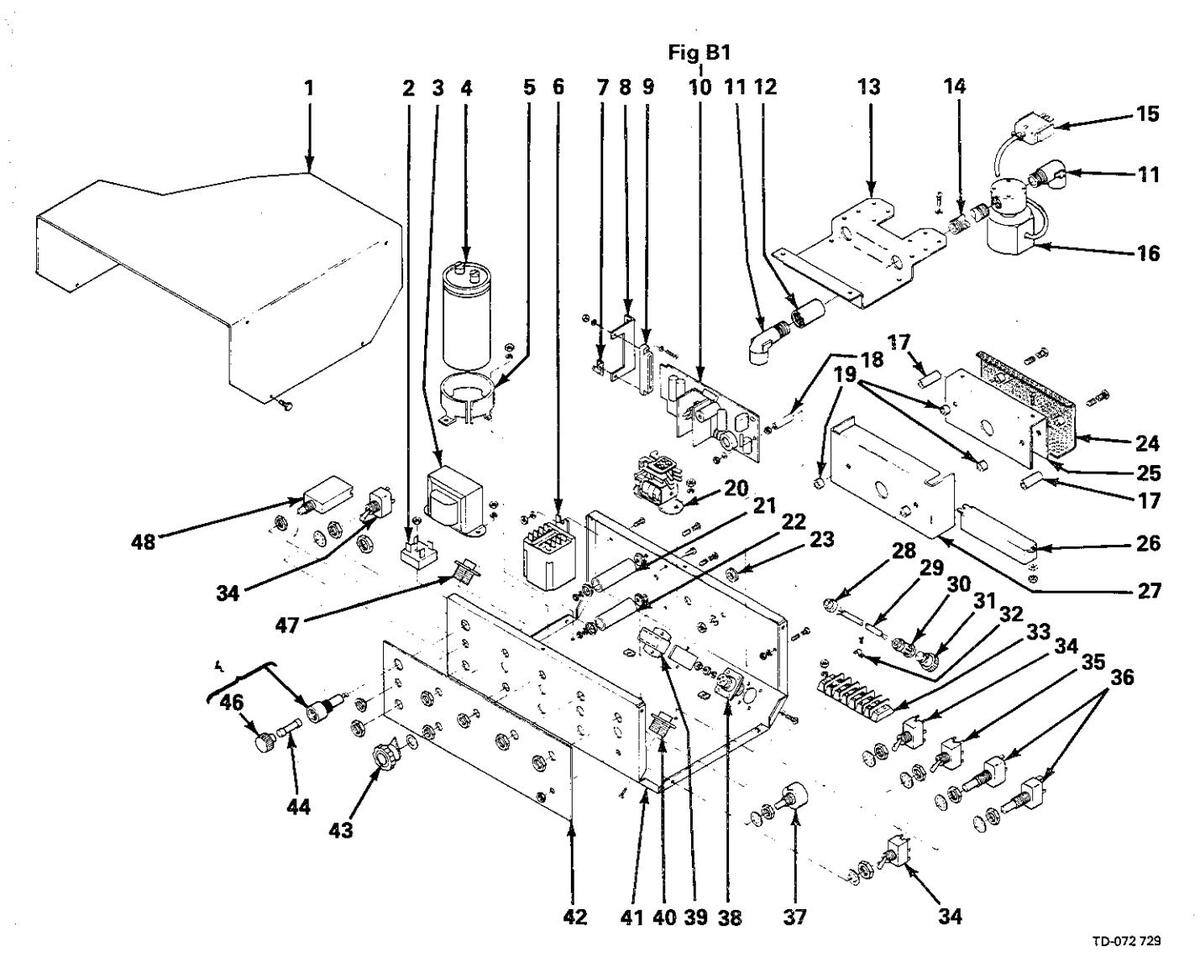
Figure B - Control Box
|
ltem
No. |
Dia.
Mkgs. |
Part
No. |
Description | Quantity |
|---|---|---|---|---|
| Figu | ıre B | 072 088 | Control Box (Fig A Pg 2 Item 25) | |
| 1 | +049 289 | WRAPPER | 1 | |
| 070 634 | LABEL, warning electric shock can kill | 1 | ||
| 2 | SR1 | 035 914 | RECTIFIER, integrated 30 emp 400 volts. | 1 |
| 3 | T1 | 047 818 | TRANSFORMER, control 115-24 volts | |
| 4 | C1 | 031 692 | CAPACITOR, electrolytic 750 uf 200 volts dc | 1 |
| 5 | 006 426 | BRACKET, mounting - capacitor | 1 | |
| 6 | CR2 | 006 393 | RELAY, 24 volts ac DPDT flanged | 1 |
| 7 | 2T | 038 784 | STRIP, terminal 1 pole | 1 |
| 8 | 045 139 | BRACKET, mounting - connector | 1 | |
| 9 | RC5 | 039 756 | TERMINAL, header 10 pin | 1 |
| 10 | PC1 | 057 314 | CIRCUIT CARD (Fig B1 Pg 5) | 1 |
| 11 | 010 296 | FITTING, hose - elbow male 1/4 NPT 5/8-18 RH | 2 | |
| 12 | 602 934 | FITTING, pipe - galvanized coupling 1/4 NPT | 1 | |
| 13 | 046 724 | BRACKET, mounting - control box | 1 | |
| 14 | 079 573 | FITTING, pipe - galvanized nipple L 1/4 NPT x 6 | 1 | |
| 15 | PLG4 | 056 265 | CONNECTOR, male 6 contact 10 amp | 1 |
| 16 | GS1 | 035 601 | VALVE, 115 volts ac 2 way 1/4 IPS port 1/8 orifice | 1 |
| 17 | 010 199 | TUBING, 0.275 ID x 0.048 wali x 1 | 2 | |
| 18 | 045 812 | BUSHING, 1/4 OD x 0.141 ID x 1 | 1 | |
| 19 | 010 193 | TUBING, 3/8 OD x 18 ga wall x 1/4 | 6 | |
| 20 | CR1 | 034 841 | RELAY, 24 volts ac DPDT | 1 |
| 21 | R13 | 079 497 | RESISTOR, WW fixed 25 watt 2000 ohm | . 1 |
| 22 | R1 | 030 651 | RESISTOR, WW fixed 25 watt 10 ohm | 1 |
| 23 | 604 311 | GROMMET, 1/4 ID x 3/8 mtg hole | 1 | |
| 24 | 056 170 | SHIELD, resistor | 1 | |
| 25 | 030 949 | HEAT SINK, rectifier | ·1 | |
| 26 | R2 | 030 941 | RESISTOR, WW fixed 100 watt 5 ohm | 1 |
| 27 | 079 683 | HEAT SINK, resistor | 1 | |
| 28 | 010 476 | BUSHING, strain - relief 5/8 x .570 hole | 1 | |
| 29 | 007 826 | CORD, No. 18 3/c (order by ft) | 3 ft | |
| 30 | 079 706 | CLAMP, cable | 1 | |
| 31 | PLG7(F) | 048 380 | HOUSING PLUG & SOCKETS (consisting of) | 1 |
| 079 534 | . TERMINAL, female | 3 | ||
| 32 | 601 219 | LINK, jumper terminal block 20 amp | 1 | |
| 33 | 1T | 038 772 | BLOCK, terminal 20 amp 6 pole | 1 |
| SN1 | t 1 10 158 | SNUBBER, poly film 0.5 uf 200 volts dc 100 ohm | 1 | |
| 34 | S1,3,6 | 011 609 | SWITCH, toggle SPDT 15 amp 125 volts ac | 3 |
| 35 | S2 | 011 059 | SWITCH, toggle DPDT 15 amp 125 volts | 1 |
| 36 | S4,5 | 011 232 | SWITCH, push button - SPDT | 2 |
| 37 | R5 | 030 943 | POTENTIOMETER, carbon 1 turn 2 watt 15K ohm | 1 |
| 38 | RC1 | 048 283 | RECEPTACLE W/PINS (consisting of) | 1 |
| 079 535 | . TERMINAL, male | 4 | ||
| 39 | RC4 | 056 266 | CONNECTOR, female 6 contact 7.5 amp | 1 |
| 40 | RC6 | 039 825 | RECEPTACLE, 6 socket MS-3102A-14S-6S | 1 |
| 41 | 046 709 | CASE SECTION, front/bottom/rear | 1 | |
| 42 | NAMEPLATE (order by model & serial number) | 1 | ||
| 43 | 097 922 | КNOB | 1 | |
| 44 | F1 | *073 426 | FUSE, miniature - glass slo blo 5 amp | 1 |
| 45 | 046 432 | HOLDER, fuse (consisting of) | 1 | |
| 46 | 059 139 | . САР | 1 | |
| 47 | 802 | 048 282 | RECEPTACLE W/SOCKETS (consisting of) | 1 |
| 17 | 079 534 | TERMINAL female | 4 | |
| 48 | CB1 | 011 991 | CIRCUIT BREAKER 1 pole 1.5 amp 250 volts | 1 |
| • |
*Recommended Spare Parts.
+ When ordering a component originally displaying a precautionary label, the label should also be ordered. †When unit has burnback option this item is deleted.
BE SURE TO PROVIDE MODEL AND SERIAL NUMBER WHEN ORDERING REPLACEMENT PARTS.
|
Dia.
Mkgs. |
Part
No. |
Description | Quantity |
|---|---|---|---|
| Fig B1 | 057 314 | Circuit Card (Fig B Pg 4 Item 10) | |
| C2,3 | 044 602 | CAPACITOR, poly film 0.47 uf 400 volts dc | 2 |
| C4,8,9 | 031 643 | CAPACITOR, ceramic 0.01 uf 500 volts dc | 3 |
| C7 | 031 693 | CAPACITOR, mylar 0.33 uf 75 volts dc | 1 |
| C10 | 031 633 | CAPACITOR, electrolytic 80 uf 25 volts dc | 1 |
| C12 | 031 721 | CAPACITOR, mylar 0.22 uf 200 volts dc | 1 |
| D1-4 | 026 202 | DIODE, 1 amp 400 volts SP | 4 |
| D5 | 037 250 | DIODE, zener 24 volts 1 watt | 1 |
| Q1 | 037 824 | THYRISTOR, 7.4 amp 200 volts | 1 |
| 037 261 | HEAT SINK | 1 | |
| 02 | 037 289 | TRANSISTOR, unijunction 50MA 35 volts | 1 |
| R3 | 030 937 | RESISTOR, carbon 0.5 watt 10 ohm | 1 |
| R4 | 030 854 | RESISTOR, carbon 0.5 watt 18K ohm | 1 |
| R6 | 030 945 | RESISTOR, carbon 2 watt 4700 ohm | 1 |
| R7,10 | 028 276 | RESISTOR, carbon 0.5 watt 2200 ohm | 2 |
| R8 | 110 429 | POTENTIOMETER, cermet 1 turn 0.5 watt 5K ohm | 1 |
| R9 | 030 936 | RESISTOR, carbon 0.5 watt 33K ohm | 1 |
| R11 | 030 938 | RESISTOR, carbon 0.5 watt 1200 ohm | 1 |
| R12 | 030 934 | RESISTOR, carbon 0.5 watt 6.8K ohm | 1 |
| R20 | 030 090 | RESISTOR, carbon 0.5 watt 47 ohm | 1 |
| T2 | 085 399 | TRANSFORMER, pulse | 1 |

TA-057 314
COMPONENTS TO BE REPLACED BY QUALIFIED PERSONNEL ONLY
Figure B1 - Circuit Card
BE SURE TO PROVIDE MODEL AND SERIAL NUMBER WHEN ORDERING REPLACEMENT PARTS.
IMPORTANT : Base selection of drive rolls upon the following recommended usages:
1. V-Groove rolls for hard wire.
2. U-Groove rolls for soft and soft shelled cored wires.
3. U-Cog rolls for extremely soft shelled wires (usually hard surfacing types).
4. Split V-Knurled rolls for hard shelled cored wires.
5. Drive roll types may be mixed to suit particular requirements (example: V-knurled roll in combination with U-groove).
| Wire Diameter & Type | Kit No.* | Roll Drive | Inlet Wire | |||
|---|---|---|---|---|---|---|
| Fraction | Decimal | Metric | Part No. Type | Guide | ||
| .023/.025'' | .023/.025 | .6MM | 087 131 | 087 130 | V-groove | 056 192 |
| .030" | .030 | .8MM | 079 594 | 053 695 | V-groove | 056 192 |
| .035'' | .035 | .9MM | 079 595 | 053 700 | V-groove | 056 192 |
| .045'' | .045 | 1.2MM | 079 596 | 053 697 | V-groove | 056 193 |
| .052′′ | .052 | 1.3MM | 079 597 | 053 698 | V-groove | 056 193 |
| 1/16″ | .062 | 1.6MM |
079 5
|
053 699 | V-groove | 056 195 |
| .035′′ | .035 | .9MM | 044 749 | 072 000 | U-groove | 056 192 |
| .045′′ | .045 | 1.2MM | 079 599 | 053 701 | U-groove | 056 193 |
| .052′′ | .052 | 1.3MM | 079 600 | 053 702 | U-groove | 056 193 |
| 1/16″ | .062 | 1.6MM | 079 601 | 053 706 | U-groove | 056 195 |
| 5/64'' | .079 | 2.0MM | 079 602 | 053 704 | U-groove | 056 195 |
| 3/32′′ | .094 | 2.4MM | 079 603 | 053 703 | U-groove | 056 196 |
| 7/64′′ | .110 | 2.8MM | 079 604 | 053 705 | U-groove | 056 196 |
| 1/8" | .126 | 3.2MM | 079 605 | 053 707 | U-groove | 056 197 |
| .035′′ | .035 | .9MM | 079 606 | 079 726 | V-knurled | 056 192 |
| .045″ | .045 | 1.2MM | 079 607 | 079 728 | V-knurled | 056 193 |
| .052″ | .052 | 1.3MM | 079 608 | 079 727 | V-knurled | 056 193 |
| 1/16" | .062 | 1.6MM | 079 609 | 056 771 | V-knurled | 056 195 |
| 5/64" | .079 | 2.0MM | 079 610 | 056 773 | V-knurled | 056 195 |
| 3/32″ | .094 | 2.4MM | 079 611 | 056 774 | V-knurled | 056 196 |
| 7/64′′ | .110 | 2.8MM | 079 612 | 056 775 | V-knurled | 056 196 |
| 1/8″ | .126 | 3.2MM | 079 613 | 056 776 | V-knurled | 056 197 |
| .045′′ | .045 | 1.2MM | 083 318 | 083 489 | U-cogged | 056 193 |
| .052″ | .052 | 1.3MM | 083 317 | 083 490 | U-cogged | 056 193 |
| 1/16″ | .062 | 1.6MM | 079 614 | 053 708 | U-cogged | 056 195 |
| 5/64'' | .079 | 2.0MM | 079 615 | 053 710 | U-cogged | 056 195 |
| 3/32" | .094 | 2.4MM | 079 616 | 053 709 | U-cogged | 056 196 |
| 7/64'' | .110 | 2.8MM | 079 617 | 053 711 | U-cogged | 056 196 |
| 1/8″ | .126 | 3.2MM | 079 618 | 053 712 | U-cogged | 056 197 |
Drive Roll & Wire Guide Kits
*When ordering replacement parts all kits listed with the exception of the V-KNURLED kits are one piece drive rolls. Two drive rolls are required for the one piece drive kits and four drive rolls for the split V-knurled kits.

Figure C - Boom
TD-080 031-C
Item Part No. No.
Description
Quantity Modei 12 16
| Figure C Boo | m (Fig A | Pg 2 | Item 35) |
|---|
| 1 | 010 313 | PIN, cotter - hair 0.072 x 1.437 | 2 | 2 |
| 2 | 079 622 | BUSHING, 0.622 ID x 0.075 x 0.501 thick | 2 | 2 |
| 3 | 079 621 | PULLEY, V single groove | 1 | 1 |
| 4 | 082 970 | SHAFT, pulley | 1 | 1 |
| 5 | 079 632 | BOLT, U 1-5/8 | 4 | 5 |
| 601 865 | NUT, hex - full 1/4-20 | 8 | 10 | |
| 602 207 | WASHER, lock - split 1/4 | 8 | 10 | |
| 6 | 079 667 | PIPE, 1/2 x 133-3/4 | 1 | |
| 6 | 080 812 | PIPE, 1/2 x 181-3/4 | 1 | |
| 7 | 079 665 | GUIDE, wire | 1 | |
| 7 | 080 811 | GUIDE, wire | 1 | |
| 8 | 079 664 | GUIDE, inlet | 1 | 1 |
| 9 | 045 391 | TUBING, 3/8 ID x 0.093 wall x 8 | 1 | 1 |
| 10 | 045 390 | LINER, monocoil 3/32 - 1/8 wire x 9 | 1 | 1 |
| 11 | 007 280 | PIN, clevis 5/8-18 x 1-7/8 | 1 | |
| 11 | 073 742 | PIN, clevis 3/4 dia x 2-5/32 | 1 | |
| 12 | 007 279 | CLEVIS | 1 | |
| 12 | 073 741 | CLEVIS | 1 | |
| 13 | 601 883 | NUT, hex-jam 5/8-18 | 1 | |
| 13 | 605 884 | NUT, hex-half 3/4-16 | 1 | |
| 14 | 075 401 | SHAFT, boom - counter balance | 1 | |
| 14 | 075 462 | SHAFT, boom - counter balance | 1 | |
| 15 | 602 250 | WASHER, flat - SAE 3/4 | 2 | 2 |
| 16 | Figure C1 | SUPPORT, hub & reel (Pg 9) | 1 | 1 |
| 17 | 601 965 | SCREW, cap - hex hd 3/8-16 x 1 | 4 | 4 |
| 18 | 602 213 | WASHER, lock - split 3/8 | 4 | 4 |
| 19 | 079 020 | NUT, hex elastic stop 3/4-16 | 1 | 1 |
| 20 | 602 249 | WASHER, flat - SAE 5/8 | 1 | |
| 20 | 075 102 | WASHER, shield 3 inch | 1 | |
| 21 | 073 663 | BEARING, ball | 1 | |
| 21 | 024 605 | BEARING, ball | 1 | |
| 22 | 075 100 | NUT, 5/8-18 x 1-1/4 special | 1 | ÷ |
| 22 | 075 101 | NUT, 3/4-16 x 1-1/4 special | 1 | |
| 23 | 602 219 | WASHER, lock - external tooth 5/8 | 1 | |
| 23 | 079 030 | WASHER, lock - external tooth 3/4 | 1 | |
| 24 | 601 883 | NUT, hex-jam 5/8-18 | 1 | , |
| 24 | 079 029 | NUT, half-full 3/4-16 | 1 | |
| 25 | 080 449 | SPRING, 2 OD x 1 ID x 12 | 2 | · |
| 25 | 080 722 | SPRING, 3-3/8 OD x 22-1/4 | 1 | |
| 26 | 075 421 | SPACER, spring - boom | 1 | |
| 26 | 048 128 | PIPE, 3 x 8 | 1 | |
| 27 | 075 403 | BEARING, thrust - boom | 1 | |
| 28 | +072 090 | BASE, swivel - boom | 1 | |
| 28 | +072 089 | BASE, swivel - boom | 1 | |
| 29 | 070 634 | LABEL, warning electric shock can kill | 1 | 1 |
| 079 423 | LABEL, caution heavy spring etc | 1 | 1 | |
| 047 702 | LABEL, remove gearing vent etc | 1 | 1 | |
| 30 | 602 246 | WASHER, flat - 1/2 | 1 | 1 |
| 31 | 047 224 | KNOB, T-bar | 1 | 1 |
| 32 | 073 666 | BOLT, hex-hd 3/4-16 x 2-3/4 | 1 | 1 |
| 33 | 082 966 | BOOM, single | 1 | |
| 33 | 082 967 | BOOM, single | - | 1 |
| 34 | 601 872 | NUT, hex-full 3/8-16 | 4 | 4 |
| 35 | 079 643 | GUARD, motor - protector | 1 | |
| 36 | 079 631 | BRACKET, hanger - gun | 1 | 1 |
+ When ordering a component originally displaying a precautionary label, the label should also be ordered. BE SURE TO PROVIDE MODEL AND SERIAL NUMBER WHEN ORDERING REPLACEMENT PARTS.
| ltem | Part |
|---|---|
| No. | No. |
Figure C1 Support, Hub & Reel (Fig C Pg 8 Item 16)
| 1 | 079 638 | SUPPORT, reel | |
| 2 | 010 191 | WASHER, fiber 5/8 ID x 1-1/2 OD x 1/8 | > |
| 3 | 058 628 | WASHER, brake | , |
| 4 | 058 428 | HUB, spool | |
| 5 | 057 971 | WASHER, flat - keyed 1-1/2 dia 1/8 | í |
| 6 | 010 233 | SPRING, compression | |
| 7 | 605 941 | WASHER, flat 41/64 ID x 1 OD | |
| 8 | 601 884 | NUT, hex 5/8-11 | |
| 9 | 058 427 | RING, retaining - spool | |
| 10 | 1056 416 | REEL, wire (consisting of) | |
| 11 | 604 051 | . NUT, wing 1/2-13 | L |
| 12 | 056 312 | . FINGER, reel | l |
| 13 | 056 313 | . STUD, 1/2-13 x 7 | ł |
| 14 | 010 224 | . PIN, spring - compression 3/16 x 1 inch | |
| 15 | 601 880 | . NUT, hex-jam 1/2-13 |
,
L |
| 16 | 056 314 | . REEL | , |

Figure C1 - Support, Hub & Reel
TC-007 886
BE SURE TO PROVIDE MODEL AND SERIAL NUMBER WHEN ORDERING REPLACEMENT PARTS.
| ltem | Part |
|---|---|
| No. | No. |
Figure D
Wire Drive & Gears (Fig A Pg 3 Item 45)
| 1 | 604 612 | SCREW, set - socket hd 8-32 x 1/8 | 2 |
| 2 | 045 233 | GUIDE, anti-wear | 1 |
| 3 | 080 211 | DRIVE ASSEMBLY (consisting of) | 1 |
| 4 | 079 671 | . HOUSING, adapter - gun/feeder | 1 |
| 5 | 085 243 | . KNOB, adjust-tension | 1 |
| 6 | 010 231 | . SPRING, compression | 1 |
| 7 | 085 244 | . WASHER, cupped 21/64 ID x 13/16 | 1 |
| 8 | 085 242 | . FASTENER, pinned | 1 |
| 9 | 010 224 | . PIN, spring - compression 3/16 x 1 | 1 |
| 10 | 601 925 | . SCREW, cap - hex hd 1/4-20 x 1/2 | 1 |
| 11 | 604 741 | , PIN, cotter - hair 0.042 x 15/16 | 1 |
| 12 | 079 669 | . LEVER, mounting - pressure gear | 1 |
| 13 | 079 634 | . PIN, hinge | 1 |
| 14 | 079 772 | . KNOB | 1 |
| 15 | 604 538 | . WASHER, flat - SAE 5/16 (as req'd) | 1 |
| 16 | 053 842 | GEAR, spur - insulated w/bearing | 1 |
| 17 | 605 518 | SCREW, cap - hex hd 1/4-20 x 1-1/4 | 1 |
| 18 | 079 626 | SCREW, fillister-hd 10-32 x 7/8 | 6 |
| 19 | 048 336 | STOP, cover | 1 |
| 20 | 602 241 | WASHER, flat - SAE 1/4 | 1 |
| 21 | 000 418 | SCREW, cap - hex hd 1/2-20 x 1/2 self - locking | 1 |
| 22 | 053 841 | GEAR, spur (consisting of) | 1 |
| 092 865 | . KEY, .122 x .123 x 3/4 | 1 | |
| 23 | 079 625 | WASHER, spring - 5/16 shakeproof | 1 |
| 24 | 082 036 | GUIDE, inlet - wire | 1 |
| 25 | 082 050 | LINER, monocoil - inlet wire | 1 |

Figure D - Wire Drive & Gears
BE SURE TO PROVIDE MODEL AND SERIAL NUMBER WHEN ORDERING REPLACEMENT PARTS.
| Dia. | Part | |
|---|---|---|
| Mkgs. | No. | Description |
| · |
Ouar
Parts For Optional Equipment
| 047 946 | BURNBACK CONTROL (consisting of) 1 | |
| R7 | 073 562 | . POTENTIOMETER, carbon 1 turn 2 watt 10K ohm |
| 024 366 | . KNOB, pointer | |
| 047 980 | . TIMER, delay 20 mil sec/20 sec 1 | |
| 110 016 | . BRACKET, burnback timer 1 | |
| 046 531 | WATER CONTROL (12 ft models) (consisting of) 1 | |
| 046 533 | WATER CONTROL (16 ft models) (consisting of) 1 | |
| WS1 | 035 601 | . VALVE, 115 volts ac 2 way 1/4 IPS port 1/8 orifice |
| 602 934 | . FITTING, pipe - nipple L 1/4 NPT x 6 | |
| 010 295 | FITTING, pipe - coupling 1/4 NPT | |
| 056 296 | . FITTING, hose - elbow male 1/4 NPT x 5/8-18 LH | |
| 008 657 | . FITTING, hose - bushing reducing 5/8-18 LH 1 | |
| 079 773 | ADAPTER, terminal - water electrode | |
| 000 572 | . HOSE, water 10 ft (12 & 16 ft models) 1 | |
| 000 570 | . HOSE, water 15 ft (12 ft models) | |
| 000 572 | . HOSE, water 19 ft 3 inches (16 ft models) | |
| 000 573 | . HOSE, water 25 ft (12 ft models) | |
| 000 569 | . HOSE, water 29 ft (16 ft models) | |
| BE SURE | DE MODEL AND SERIAL NUMBER WHEN ORDERING REPLACEMENT PARTS. |
OPTIONAL REMOTE CONTROLS


RCMP-1 Stock No. 041 125 (For use with MP series power sources) RCDW-1 Stock No. 041 510 (For use with Deltaweld series power sources) For use with the single Swingarc. Programs two welding conditions (dual schedule) on one wire. Adjusts voltages and wire feed speeds.
Mounting Bracket Stock No. 079 776 Required when installing RCMP-1, RCDW-1 and RCMP-4 on single Swingarc.
Dual Schedule Switches For use with RCMP-1, and RCDW-1 Dual Schedule Controls. DSS-8 For 10' (3 m) gun. Stock No. 079 691 (Field) DSS-8 For 15' (4.6 m) gun. Stock No. 079 693 (Field) A two-position trigger switch which attaches to the gun handle and is used in place of the standard trigger.

DSS-9 Dual Schedule Switch DSS-9 Dual Schedule Switch Stock No. 071 832 for 10 ft. (2.5 m) gun Stock No. 071 833 for 15 ft. (3.8 m) gun A two-position slide switch which attaches to the gun handle and is used to select the desired welding condition. The standard gun trigger operates the power supply contactor.
Adaptor Cord Stock No. 046 943 Required to connect dual schedule gun switches to feeder control and dual schedule control.
RCMP-4 Stock No. 080 967 (For use with MP series power sources) RCDW-4 Stock No. 041 520 (For use with Deltaweld series power sources) For use with the dual Swingarc and one power source. This control provides for adjusting the power source voltage for both wires.

RCMP-3A Stock No. 080 715 (For use with MP series power sources) RCDW-3A Stock No. 041 485 (For use with Deltaweld series power sources)
This control adjusts the power source voltage for both wires on the dual Swingarc. The RCMP-3A and RCDW-3A performs the same functions as the RCMP-4 and RCDW-4, but also has two secondary contactors. One wire can be "electrically cold" while welding with the other wire, or allows the use of different polarities (straight or reverse) on each wire, or the same polarity on both wires. NOTE: This control will not perform both polarity reversing capabilities and electrical isolation at the
same time. Mounting Bracket Stock No. 080 939 Required to mount RCMP-3A or RCDW-3A on the
dual Swingarc.
SPOT CONTROLS

Pre-Flow/Post-Flow Timer Control Stock No. 044 936 A 0 to 5 second adjustable timer to control gas flow prior to arc initiation and at completion of weld. NOTE: If pre-flow/post-flow control is required on both sides of a dual, two controls are needed.
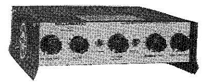
CS-4 Stock No. 045 886 Provides adjustable run-in speed, weld time to 5 sec. in two ranges. Time starts with arc. Has burnback control .25 sec., pre-flow control 5 sec., post-flow control 5 sec. and spot test switch.
NOTE: If spot control is desired on both sides of a dual, two controls are required.
TRIGGER HOLD CONTROLS
Allow the operator to make extended welds without having to hold the gun trigger.

TH-1 Stock No. 044 042 For single Swingarcs and one side of duals.
TH-2 Stock No. 044 040 For both sides of the dual Swingarc.
CS-3A Stock No. 044 935 Provides to 5 seconds of spot weld time in two ranges. Time starts with depression of gun trigger switch. Burnback control to .25 seconds.
Wire Reel Assembly Stock No. 056 416 For 60 lb. (27 kg) coil of wire.
Spool Adaptor Stock No. 047 141 For use with 14 lb. (6.3 kg) spool of Lincoln self-shielding wire.
25 Ft. (7.6 m) Extension Cable Stock No. 047 813 Connects to existing 10 ft. (3 m) 115 volt and contactor control cable. Permits Swingarc to be located 35 ft. (10.7 m) from the power source.
ACCESSORIES
Burnback Control
Recommended for use with automatic setups to eliminate wire freeze in the puddle at the completion of the weld.
SINGLE 047 945 (factory) 047 946 (field)
DUAL Left 047 945 {factory} 047 946 (field) Right 046 023 (factory) 046 024 (field)
Water Control Kit For use with water-cooled gun. Consists of solenoid valve, tube and fittings. STOCK NO. For 16' (4.9 m) Bocm
For 16' (4.9 m) Boom SINGLE OR ONE SIDE OF DUAL 046 533 (factory) 046 537 (field)
DUAL 046 534 (factory) 046 538 (fiéld)
STOCK NO. For 12' (3.7 m) Boom SINGLE OR ONE SIDE OF DUAL 046 531 (factory) 046 535 (field)
DUAL 046 532 (factory) 046 536 (field) (For Both Sides)
NOTE: Not recommended when using a recirculating system such as Radiator 1 or 2.
Interface Control Stock No. 045 031 To Lincoln and Hobart constant potential power sources requiring a continuity set of contacts for contactor control.


 Loading...