

Page 1
OM-745 201 170B
March 2003
Processes
Resistance Spot
Welding
Descriptio n
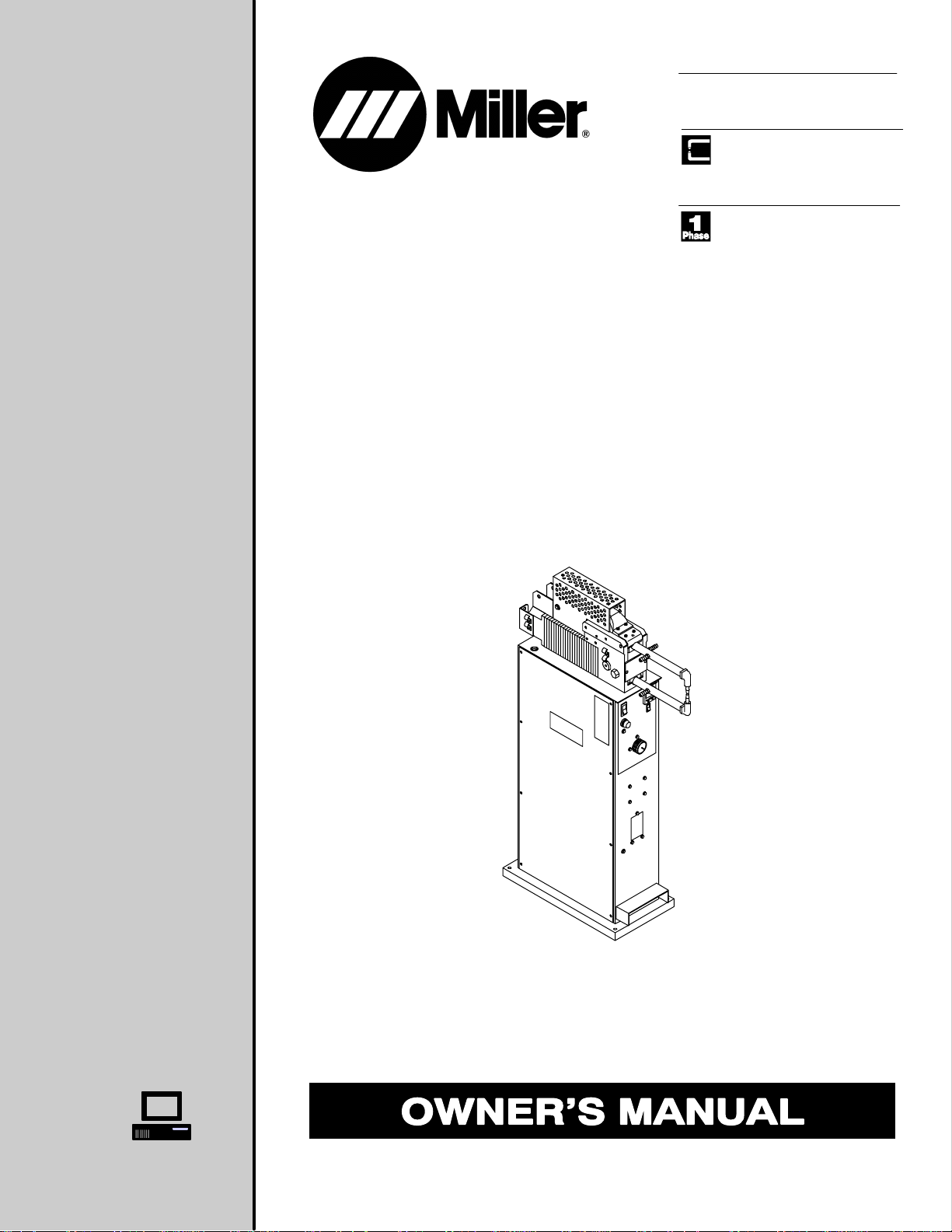
SSW-2020ATT, And SSW-2040ATT
Visit our website at
www.MillerWelds.com
Page 2
From Miller to You
Thank you and congratulations on choosing Miller. Now you can get
the job done and get it done right. We know you don’t have time to do
it any other way.
That’s why when Niels Miller first started building arc welders in 1929,
he made sure his products offered long-lasting value and superior
quality. Like you, his customers couldn’t afford anything less. Miller
products had to be more than the best they could be. They had to be the
best you could buy.
Today, the people that build and sell Miller products continue the
tradition. They’re just as committed to providing equipment and service
that meets the high standards of quality and value established in 1929.
This Owner’s Manual is designed to help you get the most out of your
Miller products. Please take time to read the Safety precautions. They
will help you protect yourself against potential hazards on the worksite.
We’ve made installation and operation quick
and easy. With Miller you can count on years
of reliable service with proper maintenance.
And if for some reason the unit needs repair,
there’s a Troubleshooting section that will
help you figure out what the problem is. The
Miller is the first welding
equipment manufacturer in
the U.S.A. to be registered to
the ISO 9001 Quality System
Standard.
parts list will then help you to decide the
exact part you may need to fix the problem.
Warranty and service information for your
particular model are also provided.
Working as hard as you do
– every power source from
Miller is backed by the most
hassle-free warranty in the
business.
Miller Electric manufactures a full line
of welders and welding related equipment.
For information on other quality Miller
products, contact your local Miller distributor to receive the latest full
line catalog orindividual catalog sheets. To locate your nearest
distributor or service agency call 1-800-4-A-Miller, or visit us at
www.MillerWelds.com on the web.
Miller offers a Technical
Manual which provides
more detailed service and
parts information for your
unit. T o obtain a Technical
Manual, contact your local
distributor. Y our distributor
can also supply you with
Welding Process Manuals
such as SMAW, GTAW,
GMAW, and GMA W-P.
Page 3

TABLE OF CONTENTS
SECTION 1 – SAFETY PRECAUTIONS - READ BEFORE USING 1. . . . . . . . . . . . . . . . . . . . . . . . . . . .
1-1. Symbol Usage 1. . . . . . . . . . . . . . . . . . . . . . . . . . . . . . . . . . . . . . . . . . . . . . . . . . . . . . . . . . . . . . . .
1-2. Resistance Spot Welding Hazards 1. . . . . . . . . . . . . . . . . . . . . . . . . . . . . . . . . . . . . . . . . . . . . . .
1-3. Additional Symbols for Installation, Operation, and Maintenance 2. . . . . . . . . . . . . . . . . . . . . .
1-4. Principal Safety Standards 2. . . . . . . . . . . . . . . . . . . . . . . . . . . . . . . . . . . . . . . . . . . . . . . . . . . . .
1-5. EMF Information 2. . . . . . . . . . . . . . . . . . . . . . . . . . . . . . . . . . . . . . . . . . . . . . . . . . . . . . . . . . . . . .
SECTION 2 – INSTALLATION 3. . . . . . . . . . . . . . . . . . . . . . . . . . . . . . . . . . . . . . . . . . . . . . . . . . . . . . . . . . .
2-1. Specifications 3. . . . . . . . . . . . . . . . . . . . . . . . . . . . . . . . . . . . . . . . . . . . . . . . . . . . . . . . . . . . . . . .
2-2. Dimensions And Weight 3. . . . . . . . . . . . . . . . . . . . . . . . . . . . . . . . . . . . . . . . . . . . . . . . . . . . . . . .
2-3. Moving The Spot Welder 4. . . . . . . . . . . . . . . . . . . . . . . . . . . . . . . . . . . . . . . . . . . . . . . . . . . . . . .
2-4. Overview Of System Connections 5. . . . . . . . . . . . . . . . . . . . . . . . . . . . . . . . . . . . . . . . . . . . . . .
2-5. Installing Or Cleaning Tongs 6. . . . . . . . . . . . . . . . . . . . . . . . . . . . . . . . . . . . . . . . . . . . . . . . . . . .
2-6. Coolant Connections 7. . . . . . . . . . . . . . . . . . . . . . . . . . . . . . . . . . . . . . . . . . . . . . . . . . . . . . . . . .
2-7. Hanging Bracket Installation (Portable Models Only) 7. . . . . . . . . . . . . . . . . . . . . . . . . . . . . . . .
2-8. Connecting Input Power 8. . . . . . . . . . . . . . . . . . . . . . . . . . . . . . . . . . . . . . . . . . . . . . . . . . . . . . . .
2-9. Electrical Service Guide 9. . . . . . . . . . . . . . . . . . . . . . . . . . . . . . . . . . . . . . . . . . . . . . . . . . . . . . . .
2-10. Air Connections 9. . . . . . . . . . . . . . . . . . . . . . . . . . . . . . . . . . . . . . . . . . . . . . . . . . . . . . . . . . . . . . .
2-11. Adjusting Tong Pressure 10. . . . . . . . . . . . . . . . . . . . . . . . . . . . . . . . . . . . . . . . . . . . . . . . . . . . . . .
SECTION 3 – OPERATION 11. . . . . . . . . . . . . . . . . . . . . . . . . . . . . . . . . . . . . . . . . . . . . . . . . . . . . . . . . . . . .
3-1. Controls 11. . . . . . . . . . . . . . . . . . . . . . . . . . . . . . . . . . . . . . . . . . . . . . . . . . . . . . . . . . . . . . . . . . . . .
SECTION 4 – MAINTENANCE AND TROUBLESHOOTING 12. . . . . . . . . . . . . . . . . . . . . . . . . . . . . . . . .
4-1. Maintenance 12. . . . . . . . . . . . . . . . . . . . . . . . . . . . . . . . . . . . . . . . . . . . . . . . . . . . . . . . . . . . . . . . .
4-2. Overload Protection 12. . . . . . . . . . . . . . . . . . . . . . . . . . . . . . . . . . . . . . . . . . . . . . . . . . . . . . . . . . .
4-3. Installing Or Dressing Tips 13. . . . . . . . . . . . . . . . . . . . . . . . . . . . . . . . . . . . . . . . . . . . . . . . . . . . . .
4-4. Troubleshooting 14. . . . . . . . . . . . . . . . . . . . . . . . . . . . . . . . . . . . . . . . . . . . . . . . . . . . . . . . . . . . . .
SECTION 5 – ELECTRICAL DIAGRAMS 15. . . . . . . . . . . . . . . . . . . . . . . . . . . . . . . . . . . . . . . . . . . . . . . . .
SECTION 6 – PARTS LIST 17. . . . . . . . . . . . . . . . . . . . . . . . . . . . . . . . . . . . . . . . . . . . . . . . . . . . . . . . . . . . . .
OPTIONS AND ACCESSORIES
WARRANTY
Page 4

Page 5
SECTION 1 – SAFETY PRECAUTIONS - READ BEFORE USING
spotom _nd_11/99
1-1. Symbol Usage
Means Warning! Watch Out! There are possible hazards
with this procedure! The possible hazards are shown in
the adjoining symbols.
Y Marks a special safety message.
. Means “Note”; not safety related.
1-2. Resistance Spot Welding Hazards
Y The symbols shown below are used throughout this manual to
call attention to and identify possible hazards. When you see
the symbol, watch out, and follow the related instructions to
avoid the hazard. The safety information given below is only
a summary of the more complete safety information found in
the Safety Standards listed in Section1-4. Read and follow all
Safety Standards.
Y Only qualified persons should install, operate, maintain, and
repair this unit.
Y During operation, keep everybody, especially children, away.
SPOT WELDING can cause fire.
Sparks can fly off from the weld. The flying sparks,
hot workpiece, and hot equipment can cause fires,
burns, and explosions.
D Protect yourself and others from flying sparks and hot metal.
D Do not spot weld where flying sparks can strike flammable material.
D Remove all flammables within 35 ft (10.7 m) of the weld. If this is not
possible, tightly cover them with approved covers.
D Be alert that welding sparks can easily go through small cracks and
openings to adjacent areas.
D Watch for fire, and keep a fire extinguisher nearby.
D Do not spot weld on closed containers such as tanks or drums.
D Do not weld where the atmosphere may contain flammable dust,
gas, or liquid vapors (such as gasoline).
D Remove any combustibles, such as a butane lighter or matches,
from your person before doing any welding.
D After completion of work, inspect area to ensure it is free of sparks,
glowing e m b e r s , a n d f l a m e s .
D Do not exceed the equipment rated capacity.
D Use only correct fuses or circuit breakers. Do not oversize or
bypass them.
This group of symbols means Warning! Watch Out! possible
ELECTRIC SHOCK, MOVING PARTS, and HOT PARTS hazards.
Consult symbols and related instructions below for necessary actions
to avoid the hazards.
D Properly install and ground this equipment according to this manual
and national, state, and local codes.
D Check and be sure that input power cord ground wire is properly
connected t o ground terminal in disconnect box or that cord plug is
connected to a properly grounded receptacle outlet – always
double-check the supply ground before applying power.
D When making input connections, attach the grounding conductor
first – double- c h e c k c o n n e c t i o n s .
D Keep cords dry, free of oil and grease, and protected from hot metal
and sparks.
D Frequently inspect input power cord and ground conductor for dam-
age or bare wiring – replace immediately if damaged – bare wiring
can kill. Check ground conductor for continuity.
D Turn off all equipment when not in use.
D For water-cooled equipment, check and repair or replace any leak-
ing hoses or fittings. Do not use any electrical equipment if you are
wet or in a wet area.
D Use only well-maintained equipment. Repair or replace damaged
parts at once.
D Wear a safety harness if working above floor level.
D Keep all panels, covers, and guards securely in place.
FLYING SPARKS can cause injury.
Very often sparks fly of f from the joint area.
D Wear approved face shield or safety goggles
with side shields.
D Wear protective garments such as oil-free, flame-resistant leather
gloves, heavy shirt, cuffless trousers, high shoes, and a cap.
Synthetic material usually does not provide such protection.
D Protect others in nearby areas by using approved flame-resistant or
noncombustible fire curtains or shields. Have all nearby persons
wear safety glasses with side shields.
ELECTRIC SHOCK can kill.
Touching live electrical parts can cause fatal shocks
or severe burns. The input power circuit and
machine internal circuits are also live when power is
on. Incorrectly installed or improperly grounded
equipment is a hazard.
D Do not touch live electrical parts.
D Wear dry , hole-free insulating gloves and body protection.
D Disconnect input power before installing or servicing this equip-
ment. Lockout/tagout input power according to OSHA 29 CFR
1910.147 (see Safety Standards).
HOT METAL can cause burns.
Wear gloves or allow cooling period before servicing
tongs or tips.
D Always wear welding-type, insulated gloves
when using this equipment.
D Do not touch workpiece, tips, or tongs with bare hands.
D Allow tongs and tips to cool before touching.
OM-745 Page 1
Page 6
MOVING PARTS can cause injury.
FUMES can be hazardous.
The tong tips, tongs, and linkages move during
operation.
D Keep away from moving parts.
D Keep away from pinch points.
D Do not put hands between tips.
D Keep all guards and panels securely in place.
D OSHA and/or local codes may require additional guarding to suit
the application.
D Do not breathe the fumes.
D If inside, ventilate the area and/or use exhaust at the weld to remove
fumes.
D In confined spaces, use an approved air-supplied respirator.
D Do not weld on coated metals, such as galvanized, lead, or cad-
mium plated steel, unless the coating is removed from the weld
area, the area is well ventilated, or if necessary, while wearing an
air-supplied respirator. The coatings and any metals containing
these elements can give off toxic fumes if welded.
D Read the Material Safety Data Sheets (MSDSs) and the manufac-
turer’s instructions for metals, coatings, and cleaners.
Coatings, cleaners, paints, and platings can produce fumes when welded. Breathing these fumes
can be hazardous to your health.
1-3. Additional Symbols For Installation, Operation, And Maintenance
FIRE OR EXPLOSION hazard.
D Do not install or place unit on, over, or near
combustible surfaces.
D Do not install or operate unit near flammables.
D Do not overload building wiring – be sure power supply system is
properly sized, rated, and protected to handle this unit.
FALLING EQUIPMENT can cause injury.
D Use equipment of adequate capacity to lift the
unit.
D Have two people of adequate physical strength
lift portable units.
D Secure unit during transport so it cannot tip or fall.
MAGNETIC FIELDS can affect pacemakers.
D Pacemaker wearers keep away.
D Wearers should consult their doctor before go-
ing near resistance spot welding operations.
OVERUSE can cause OVERHEATING.
D Allow cooling period; follow rated duty cycle.
D Reduce duty cycle before starting to weld
again.
FLYING ME TAL or DIRT can injure eyes.
D Wear approved safety glasses with side
shields or wear face shield.
1-4. Principal Safety Standards
Safety in Welding and Cutting, ANSI Standard Z49.1, from American
Welding Society, 550 N.W. LeJeune Rd, Miami FL 33126
Safety and Health Standards, OSHA 29 CFR 1910, from Superintendent of Documents, U.S. Government Printing Office, Washington, D.C.
20402.
National Electrical Code, NFPA Standard 70, from National Fire Protec-
tion Association, Batterymarch Park, Quincy, MA 02269.
1-5. EMF Information
Considerations About Welding And The Effects Of Low Frequency
Electric And Ma g netic Fields
Welding current will cause electromagnetic fields. There has been and
still is some concern about such fields. However, after examining more
than 500 studies spanning 17 years of research, a special blue ribbon
Code for Safety in Welding and Cutting, CSA Standard W1 17.2, from
Canadian Standards Association, Standards Sales, 178 Rexdale Boulevard, Rexdale, Ontario, Canada M9W 1R3.
Safe Practices For Occupation And Educational Eye And Face Protec-
tion, ANSI Standard Z87.1, from American National Standards Institute,
1430 Broadway, New York, NY 10018.
Cutting And Welding Processes, NFPA Standard 51B, from National
Fire Protection Association, Batterymarch Park, Quincy, MA 02269.
committee of the National Research Council concluded that: “The body
of evidence, in the committee’s judgment, has not demonstrated that
exposure to power-frequency electric and magnetic fields is a humanhealth hazard.” However, studies are still going forth and evidence
continues t o b e examined.
OM-745 Page 2
Page 7
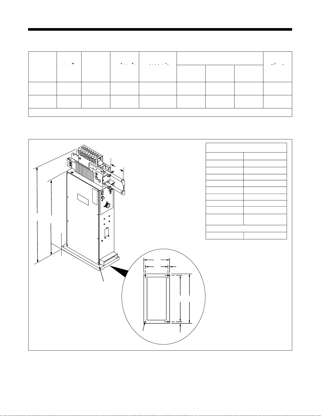
2-1. Specifications
Input
Work
Rated Output Amperes
Input
Work
Rated Output Amperes
ATT
Voltage
Input
Capacity
l
Rated Output
Open-
SECTION 2 – INSTALLATION
Voltage
Models
50/60 Hz
AC
Amps
1-Phase
SSW-2020
SSW-2040
*Based on 10 second time period; means unit can weld for 5 seconds out of each 10 second time period.
230 90
460 45
Capacity
Combined
Thickness
Mild Stee
1/4 in
(6.3 mm)
1/4 in
(6.3 mm)
Rated Output
At Listed
Duty Cycle*
20 kVA
40%
20 kVA
40%
At Listed Tong Length
6 in
(152 mm)
12,500 10,500 9000 3.55
12,500 10,500 9000 3.55
(305 mm)
2-2. Dimensions And Weight
C
A
B
SSW-2020, 2040 185 lb (84 kg)
Open-
12 in
18 in
(457 mm)
Circuit
Voltage
Dimensions
A 49 in (1245 mm)
B 37-1/8 in (943 mm)
C*
D 10-7/8 in (276 mm)
E 9-1/2 in (241 mm)
F 11/16 in (18 mm)
G 19-1/2 in (495 mm)
H 20-7/8 in (530 mm)
I 11/16 in (18 mm)
J 1/2 in (13 mm)
Dia. 4 Holes
Weight
Y Bolt unit to floor to keep
it from falling over.
D
E
J
J
F
GH
*Dimension depends upon length of tongs.
See Parts List for sizes.
Ref. 802 751
OM-745 Page 3
Page 8
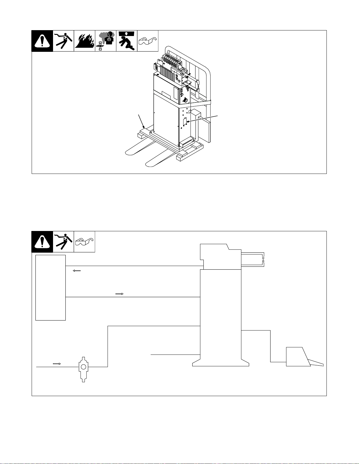
2-3. Moving The Spot Welder
1 Rating Label
Locate unit near correct input
power supply.
2 Skid
Place unit on skid and secure with
straps.
2
2-4. Overview Of System Connections
SSW Models
Coolant
system
Coolant line (see Section 2-6)
Normally 5/8–18 left–
hand threaded receptacles
Coolant line
Slip–on hoses
tighten with
hose clamps
1
802 752
Spotwelder
Air in
Air filter/regulator assembly
OM-745 Page 4
Pedestal
Air hose 60 – 100 PSI (see Section 2-10)
Input power line (see Section 2-8)
Foot switch
802 792-A
Page 9
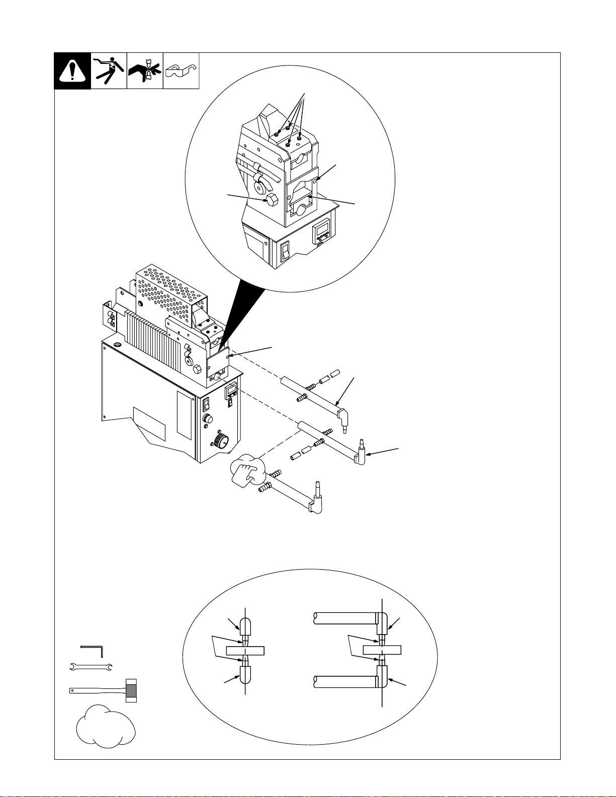
2-5. Installing Or Cleaning Tongs
4
Y OSHA and/or local codes may require addi-
tional guarding to suit the application.
Y Turn off unit and disconnect
input power.
6
3
2
1
7
. Be sure tong ends are clean
and not corroded before installing. Clean tongs with fine steel
wool.
Bottom Tong Installation:
1 Spatter Guard
2 Insulating Strip
Check to see that insulating strip is
not cracked.
Y Electric shock hazard and
possible transformer damage from incorrect part. Do
not replace polyester glass
insulating strip with a metal
strip – use only proper parts
from Parts List.
3 Setscrew
Loosen setscrew.
4 Cam Nut
Turn nut counterclockwise to re-
lease pressure on bottom tong.
5 Bottom Tong
Slide tong into bottom tong holder
as far as possible, and position so
that tip is pointing straight up.
Turn cam nut clockwise to secure
tong in holder.
Tighten setscrew to lock cam in
place.
Top Tong Installation:
6 Top Tong Securing Screws
Loosen the four screws.
7 Top Tong
5
8 Tips
Slide tong into top tong holder as far
as necessary, so that tip mates with
bottom tip when tongs are closed.
Adjust tong positions to line up centers of tips as shown.
Tighten securing screws to lock
tong in place.
Fine
Steel
Wool
3/16 in
9/16 in
Tong Alignment
7
8
5
Front View Side View
7
8
5
802 754 / 801 436 / Ref. 800 154-A
OM-745 Page 5
Page 10
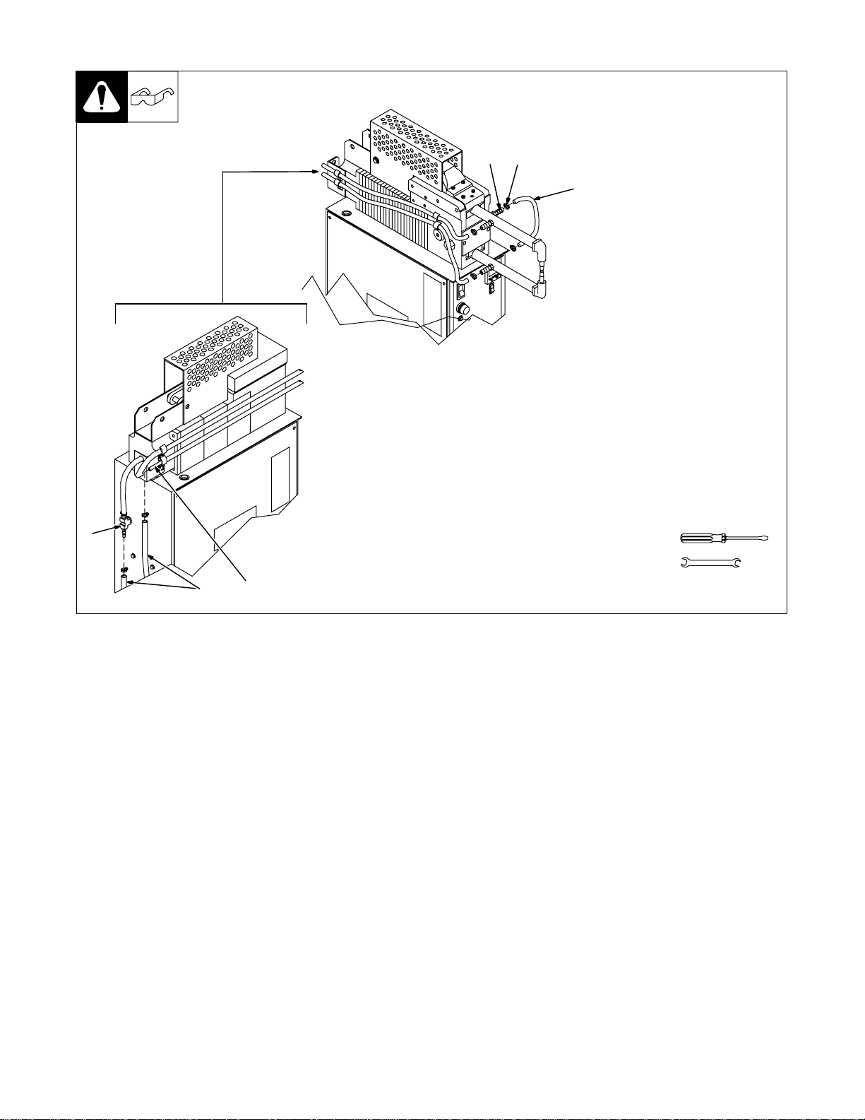
2-6. Coolant Connections
4
23
. It is recommended that a coolant which contains
a base of ethylene glycol and deionized water
such as low-conductivity coolant solution, Part
No. 043 810, be used to protect against freezing
to -37 F (-38 C) or boiling to 227 F (108 C). It
also contains a compound that resists algae
growth.
Y Turn off power and coolant
supply until installation is
complete.
1 Tong Coolant Hose
2 Hose Clamp
3 Barbed Fitting
4 Coolant-In Fitting
1
5 Coolant-Out Tube
6 Coolant Hoses (Customer
Supplied)
Install hoses as shown.
. This unit is equipped with a
water control pressure switch
to insure proper cooling. If
there i s not enough pressure to
close the switch, the unit will
not weld. For proper operation,
coolant supply must have a
minimum pressure of 30 psi
(207 kPa), a maximum temperature of 86° F (30° C), and a
flow rate of 2.5 to 3 qt/min (2.4
to 2.8 L/min).
Obtain two hoses of desired length
with 5/16 in (7.9 mm) inside
diameter.
Connect hoses as shown, and secure with hose clamps.
5/8 in
6
5
Ref. 802 755 / Ref. 802 758
OM-745 Page 6
Page 11
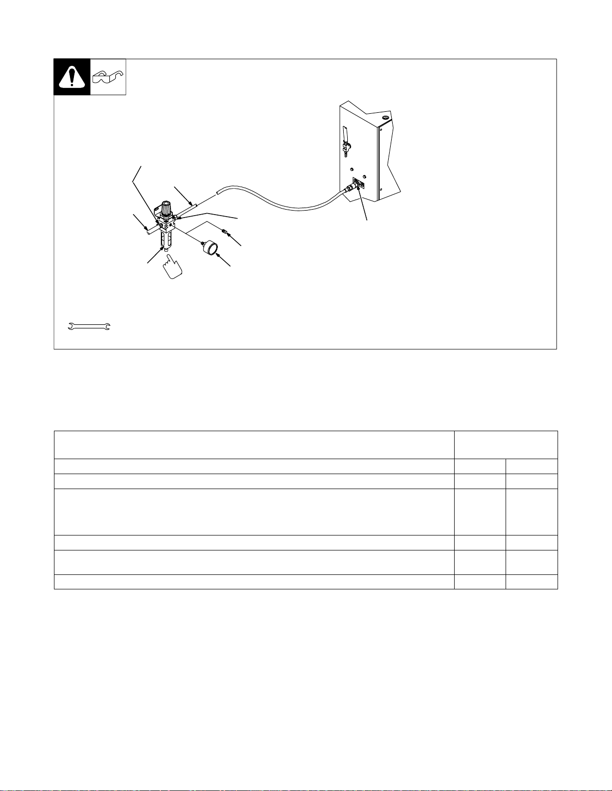
2-7. Air Connections
1/4 Inch
Pipe Thread
1
1
2
5/8 in
1/4 Inch Pipe Thread
3
5
See manufacturer’s instructions supplied with
filter/regulator (FR) assembly for complete
installation and preparation instructions.
Y Turn off power and air supply
until installation is complete.
1 Air Hoses (Customer
Supplied)
Obtain two hoses of correct size,
type, and length. Air-In fittings on
control boxes have 5/8-18 left-hand
threads.
2 Air Filter
Connect one hose to air supply and
other end to input fitting on the
regulator.
3 Regulator Plug
4 Regulator
6
5 Pressure Gauge
Remove appropriate regulator plug
and install pressure gauge.
Set regulator so air pressure is in
the 60 to 100 psi (414 to 689 kPa)
range.
6 Air-In Fitting
Connect one end of remaining hose
to regulator output fitting, and connect other end to Air-In fitting.
Ref. 802 761-A
2-8. Electrical Service Guide
20 KVA
Single Phase
Input Voltage 230 460
Input Amperes At Rated Output 90 45
Max Recommended Standard Fuse Rating In Amperes
Time-Delay
Normal Operating 3 125 70
Min Input Conductor Size In AWG/Kcmil 6 10
Max Recommended Input Conductor Length In Feet (Meters)
Min Grounding Conductor Size In AWG/Kcmil 6 10
Reference: 1999 National Electrical Code (NEC)
1 Consult factory for circuit breaker applications.
2 “Time-Delay” fuses are UL class “RK5” .
3 “Normal Operating” (general purpose - no intentional delay) fuses are UL class “K5” (up to and including 60 amp), and UL class “H” ( 65 amp and
above).
1
2
110 50
78
(24)
131
(40)
OM-745 Page 7
Page 12
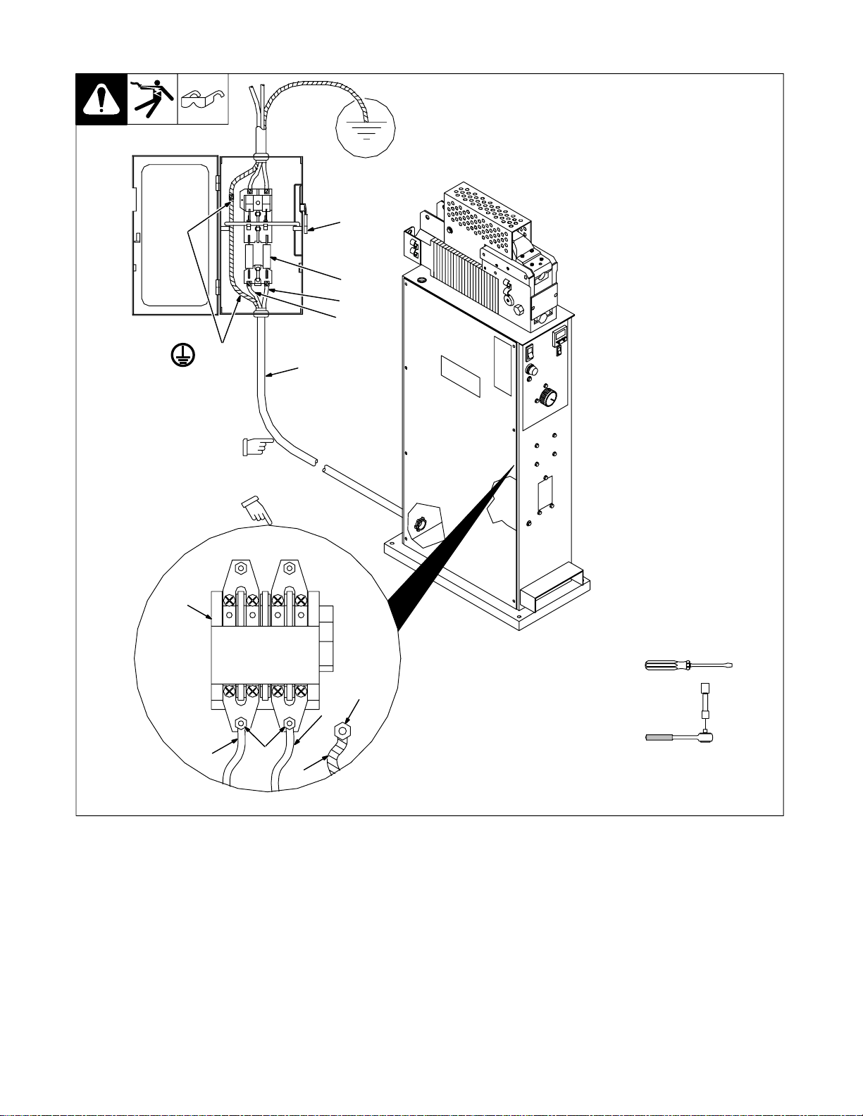
2-9. Connecting Input Power
= GND/PE
Y Always connect green or
green/yellow grounding
conductor first.
Install conductors into a deenergized line disconnect device.
Make connections to machine
first and supply last.
3
2
Y Disconnect and lockout/tag-
out input power before connecting input conductors
from unit.
Have only qualified persons make
this installation.
Remove left side panel.
1 Line Disconnect Device
1
7
L2
L1
2 Input And Grounding Conduc-
tors
Select size and length using Section 2-8. Conductors must comply
with national, state, and local electrical codes. If applicable, use lugs
of proper amperage capacity and
correct hole size.
Y Make input power connec-
tions to the machine before
making connections into a
deenergized line disconnect
device. I n the line disconnect
device, always connect
green or green/yellow
grounding conductor to supply grounding terminal first,
never to a line terminal.
3 Contactor
4 Line Terminals
5 Grounding Conductor
6 Ground Terminal
Reinstall side panel.
7 Overcurrent Protection
(Fuses Shown)
Select type and size using Section
2-8.
OM-745 Page 8
6
L2
4L1
5
3/8, 1/2 in
Ref. 802 760
Page 13
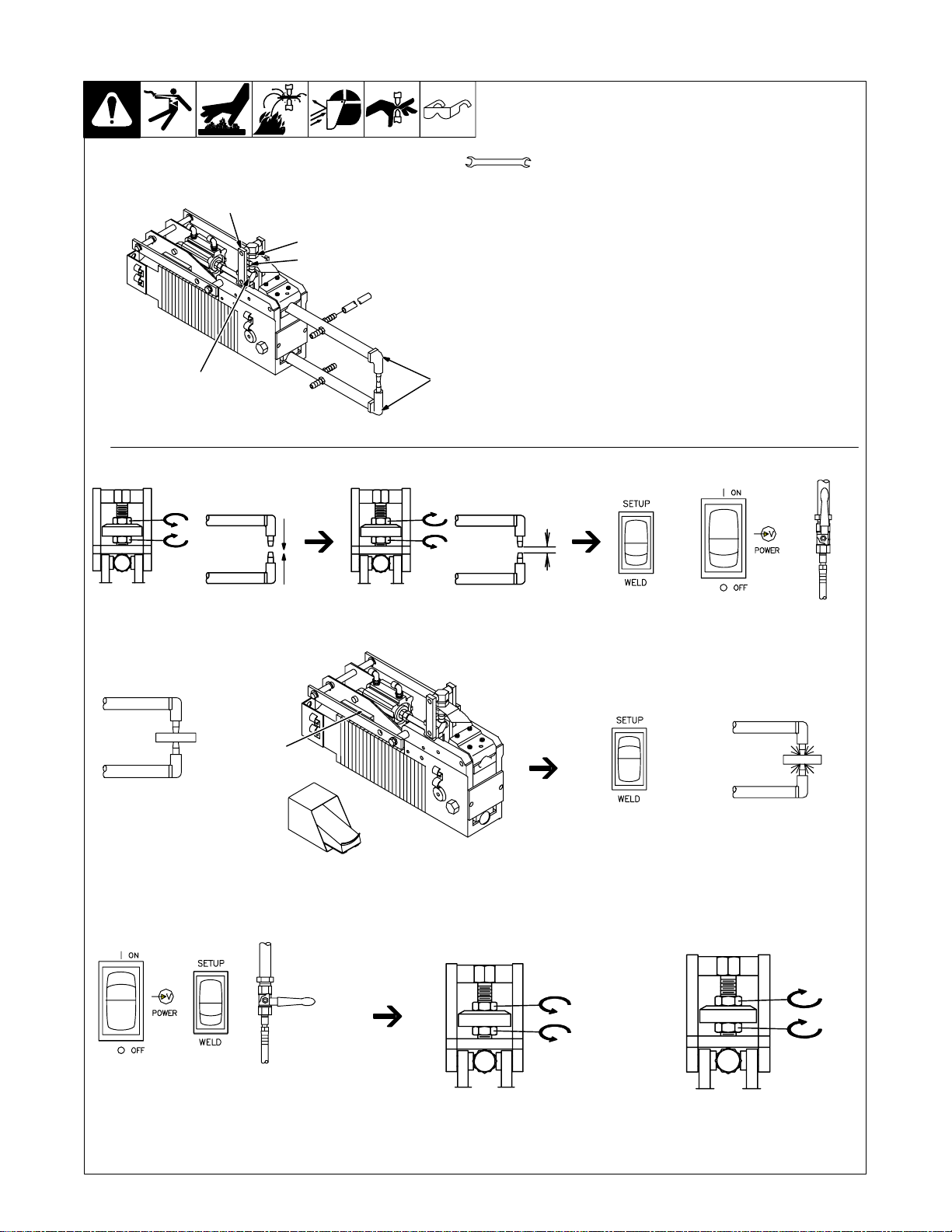
2-10. Adjusting Tong Pressure
3
1
2
4
Y Turn off power before mak-
ing adjustments.
1 Top Nut
13/16 in
2 Bottom Nut
3 Top Linkage
4 Bottom Linkage
5 Tongs
. Tong pressure must be checked and/or set before operation.
Correct tong pressure is necessary to create a quality weld and to
prevent damage to tips.
Too much tong pressure causes the weld nugget to dimple and material to splash out around the nugget area.
If tong pressure is too weak, parts are loose when the tongs are
closed, severe arcing occurs between workpieces, and no weld
5
can be made.
Step 1 Step 2
Loosen both nuts and
push tong tips together.
Step 4 Step 5
Start
Place material to be welded between
tong tips, and press start switch or re-
mote foot control (see Section 3-1).
Begin to tighten top nut. This causes tong tips to
open. Stop when opening is a little less than thickness of material to be welded. Tighten bottom nut.
OR
Step 3
Set controls.
If tong pressure appears correct, place Weld switch in Weld
position and try a sample weld according to Section 3-1.
Air Supply On
Step 6 Step 7
Air Supply
Set controls. If tong pressure is
correct, stop here. If further adjust-
ment is required, go to next step.
Off
To INCREASE tong pressure, loosen top
nut 1/4 turn. Tighten bottom nut, turn air
and Power On, and go to Step 4.
Step 8
To DECREASE tong pressure, loos-
en bottom nut 1/4 turn. Tighten top
nut, turn air and Power On, and go
to Step 4.
Ref. 802 762 / Ref. 161 768-B
OM-745 Page 9
Page 14
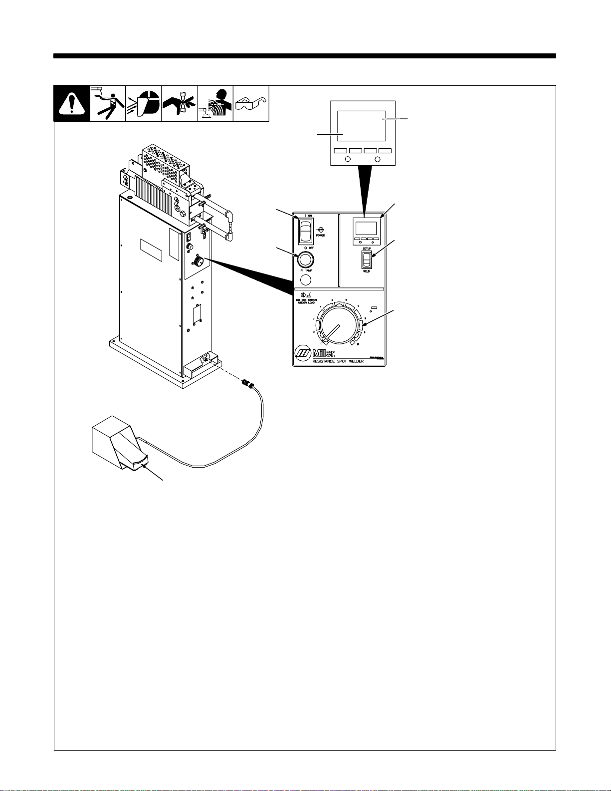
3-1. Controls
SECTION 3 – OPERATION
Second row of LCDs
displays squeeze time
set or weld time set.
4321
ST
WT
First row of LCDs displays
actual time set.
4
5
6
1
2
3
1 Time Control
Squeeze Time (ST) - Use control to set
enough time for tongs to close and apply full
pressure to the work before weld amperage
starts. Push ST button, then use buttons 3,
2, 1 to select squeeze time from 0 to 9.99 seconds. Squeeze time begins when the Remote Foot Switch or Start Switch is pressed.
Weld Time (WT) - Push WT button, then use
buttons 3, 2 , 1 t o select spot weld time from
0 to 9.99 seconds.
Weld time begins at the end of the squeeze
time cycle.
2 Weld Switch
Use control to check tong pressure and
alignment without weld amperage present at
the tongs. When the switch is in the Set Up
position, pressing the Remote Foot Switch
OM-745 Page 10
or Start Switch closes the tongs without
starting weld amperage. When the switch is
in the Weld position, tongs have weld amperage present after the squeeze time has
ended.
3 Weld Amperage Control
Turn clockwise to increase current. Chang-
ing the weld current value does not affect the
duty cycle rating. The scale is for reference
only.
4 Power/Pilot Light/Circuit Breaker
Switch
Use switch to turn On power and pilot light.
See Section 4-2 for circuit breaker operation.
802 751 / 200 264-A
5 Fuse F1
See Section 4-2.
6 Remote Foot Switch
Use remote foot switch to close tongs and
start squeeze time.
If switch is released before squeeze time
ends, the tongs open, and the unit resets for
another weld cycle.
If switch is held until squeeze time ends and
weld time starts, the switch may be released,
and the tongs will stay closed until weld time
ends.
If workpiece is to be left between tongs after
weld time ends, switch must be held for
whatever hold time is desired after welding
ends.
Page 15
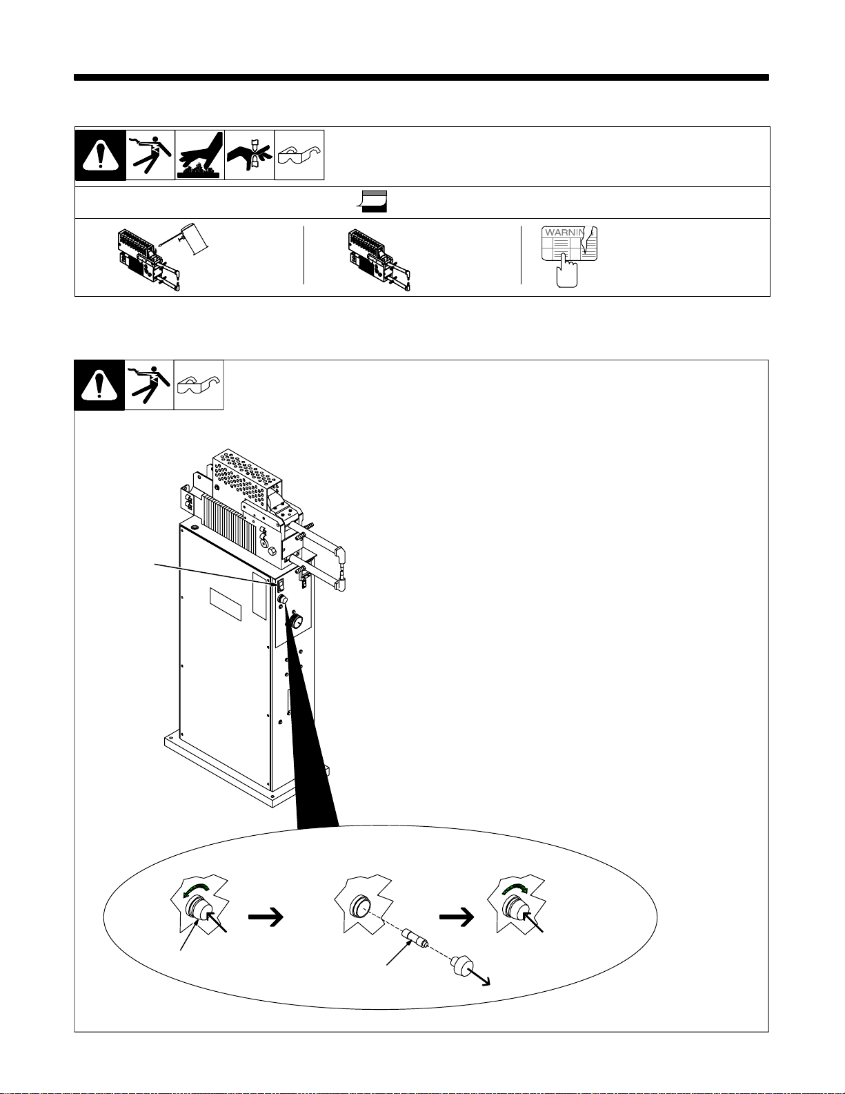
SECTION 4 – MAINTENANCE AND TROUBLESHOOTING
4-1. Maintenance
Y Disconnect power before maintaining.
. During heavy service, maintain monthly.
3 Months
Oil Unit
4-2. Overload Protection
3
Inspect
Tips
Replace Damaged
Or Unreadable
Labels
Y Turn Off power before
checking fuse.
Fuse F1 and Power/pilot light/circuit breaker switch S1 protect the
control circuitry.
If either the fuse or the circuit breaker opens, the unit shuts down. Turn
switch On to reset breaker. To replace a fuse, proceed as shown:
1 Fuse Holder Cover
2 Fuse (See Parts List)
3 Power/Pilot Light /Circuit
Breaker Switch
If a fuse continues to open, or the
circuit breaker continues to trip,
contact Factory Authorized Service
Agent.
1
2
802 763
OM-745 Page 11
Page 16
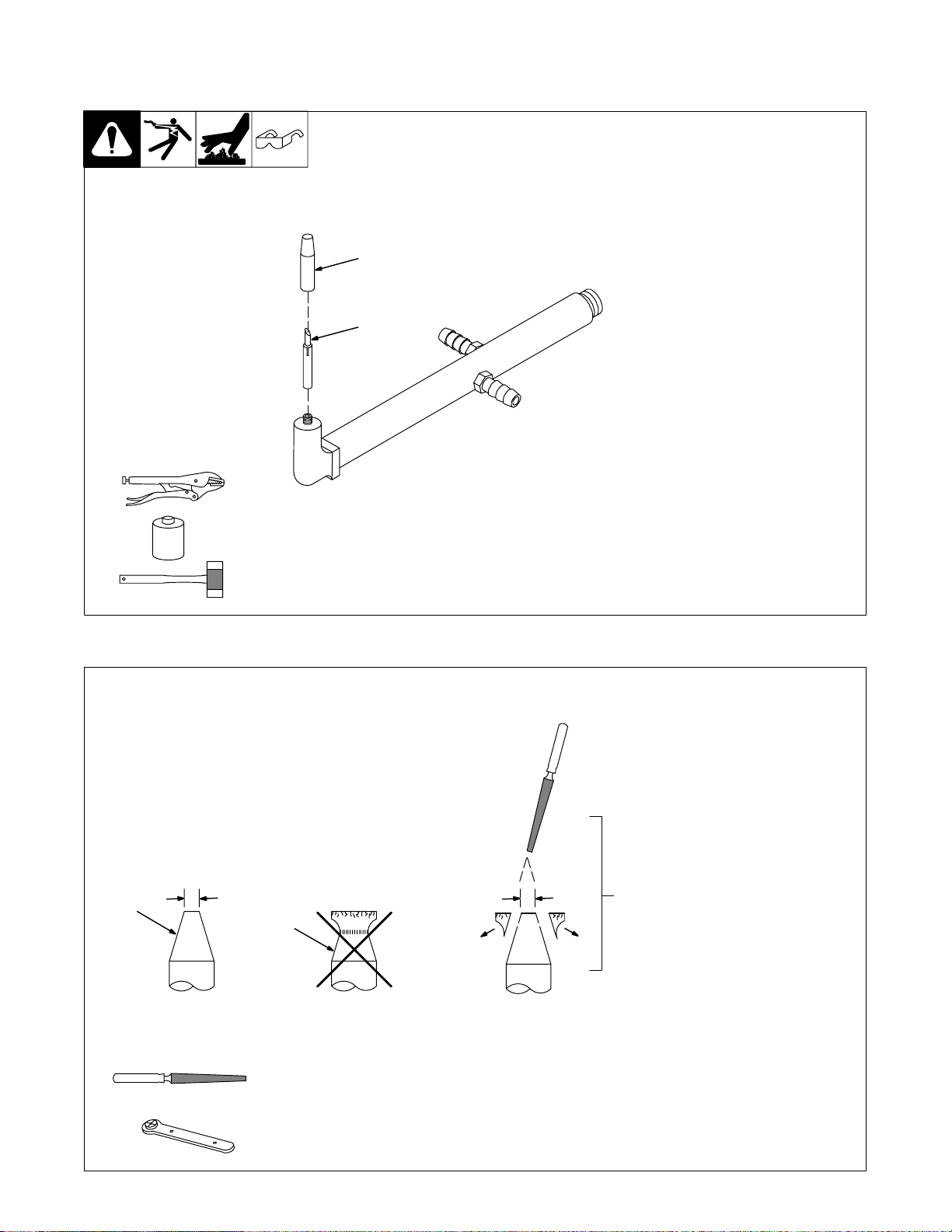
4-3. Installing Or Dressing Tips
A. Installing Tips
1
2
Y Turn off power before re-
moving tips.
1Tip
2 Telescoping Tube
Removal:
Tips have a Morse Taper and a
press fit.
. Use a vice grip pliers to rotate
and loosen tips. Once loose,
pull tips straight out.
Y Do not move tips from side to
side when removing or telescoping tube will snap off.
Installation:
Coat taper area of tip with pipe
sealant compound. Pull telescoping tube all the way up, but not
out. Use a plastic or leather
hammer to tap tip into seat. Run
water through tong to check for
leaks.
Repeat if necessary.
B. Dressing Tips
d = 3/16–1/4 in (4.8–6.4 mm)
diameter
1
ST-801 437
1 New Tip
2 Used Tip Requiring Dressing
3 Dressing Method – Keep top
diameter same as a new tip.
3d d
2
OM-745 Page 12
OR
Page 17
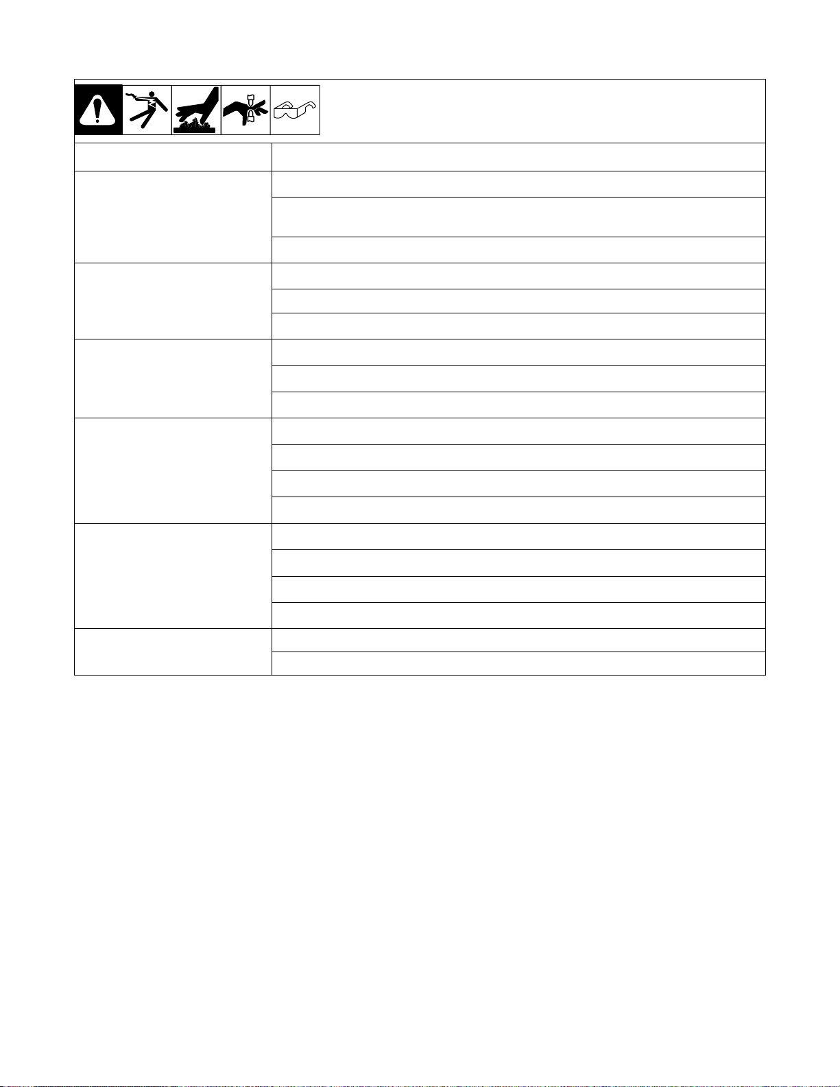
4-4. Troubleshooting
Trouble Remedy
No weld output; pilot light Off. Check line fuses, and replace if necessary (see Section 2-9).
Check fuse F1 and/or Power/pilot light/circuit breaker switch S1, and replace if necessary (see Section
4-2).
Turn On Power/pilot light/circuit breaker switch S1.
No weld output, pilot light on. Check for proper coolant supply pressure (see Section 2-6).
Place Weld Switch S3 in the Weld position (see Section 3-1).
Have Factory Authorized Service Agent check contactor W.
Low weld output; pilot light On. Dress or replace tips (see Section 4-3).
Remove and clean ends of tongs and tong holders (see Section 2-5).
Adjust tong pressure (see Section 2-10).
Longer than normal W eld Time required. Dress or replace tong tips (see Section 4-3).
Clean workpieces.
Adjust tong pressure (see Section 2-10).
Check input line voltage.
Burn through at point of weld. Shorten weld time (see Section 3-1).
Adjust tong pressure (see Section 2-10).
Dress or replace tong tips (see Section 4-3).
Realign tips (see Section 2-5).
Tongs close too slowly . Check air pressure at source and at regulator (see Section 2-7).
Have Factory Authorized Service Agent check and replace air valve, if necessary.
OM-745 Page 13
Page 18
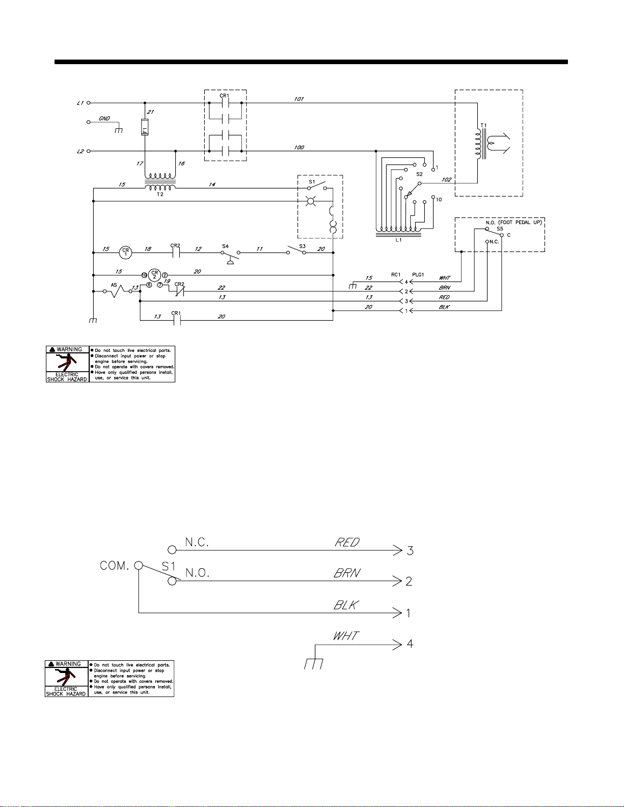
SECTION 5 – ELECTRICAL DIAGRAMS
Figure 5-1. Circuit Diagram For Stationary Models
199 202
OM-745 Page 14
200 302-A
Figure 5-2. Circuit Diagram For Foot Control
Page 19
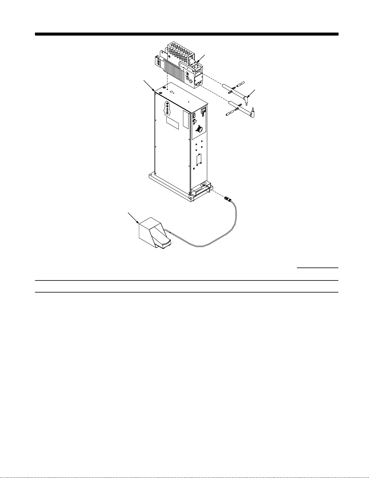
. Hardware is common and
not available unless listed.
SECTION 6 – PARTS LIST
Figure 6-2
Figure 6-4
Figure 6-5
Figure 6-3
802 764
Figure 6-1. Main Assembly
Quantity
Part
No.
Description
Model
SSW-
2020ATT
2040ATT
Figure 6-1. Main Assembly
209 661 FILTER/REGULATOR 1. . . . . . . . . . . . . . . . . . . . . . . . . . . . . . . . . . . . . . . . . . . . . . . . . . . . . . . . . . . . . . . . .
Fig 6-2 RESISTANCE SPOT WELDER, air 1. . . . . . . . . . . . . . . . . . . . . . . . . . . . . . . . . . . . . . . . . . . . . . . . . . . . . .
Fig 6-4 PEDESTAL, air operated 1. . . . . . . . . . . . . . . . . . . . . . . . . . . . . . . . . . . . . . . . . . . . . . . . . . . . . . . . . . . . . . .
Fig 6-3 RFSW-10/20 1. . . . . . . . . . . . . . . . . . . . . . . . . . . . . . . . . . . . . . . . . . . . . . . . . . . . . . . . . . . . . . . . . . . . . . . . . .
Fig 6-6 TONGS, (Optional) 1. . . . . . . . . . . . . . . . . . . . . . . . . . . . . . . . . . . . . . . . . . . . . . . . . . . . . . . . . . . . . . . . . . . .
603 105 HOSE, nprn brd No. 1 x .312 ID (order by ft) 7ft. . . . . . . . . . . . . . . . . . . . . . . . . . . . . . . . . . . . . . . . . . . . .
010 323 CLAMP, hose .250 -.625clp dia 8. . . . . . . . . . . . . . . . . . . . . . . . . . . . . . . . . . . . . . . . . . . . . . . . . . . . . . . . .
To maintain the factory original performance of your equipment, use only Manufacturer’s Suggested
Replacement Parts. Model and serial number required when ordering parts from your local distributor.
OM-745 Page 15
Page 20
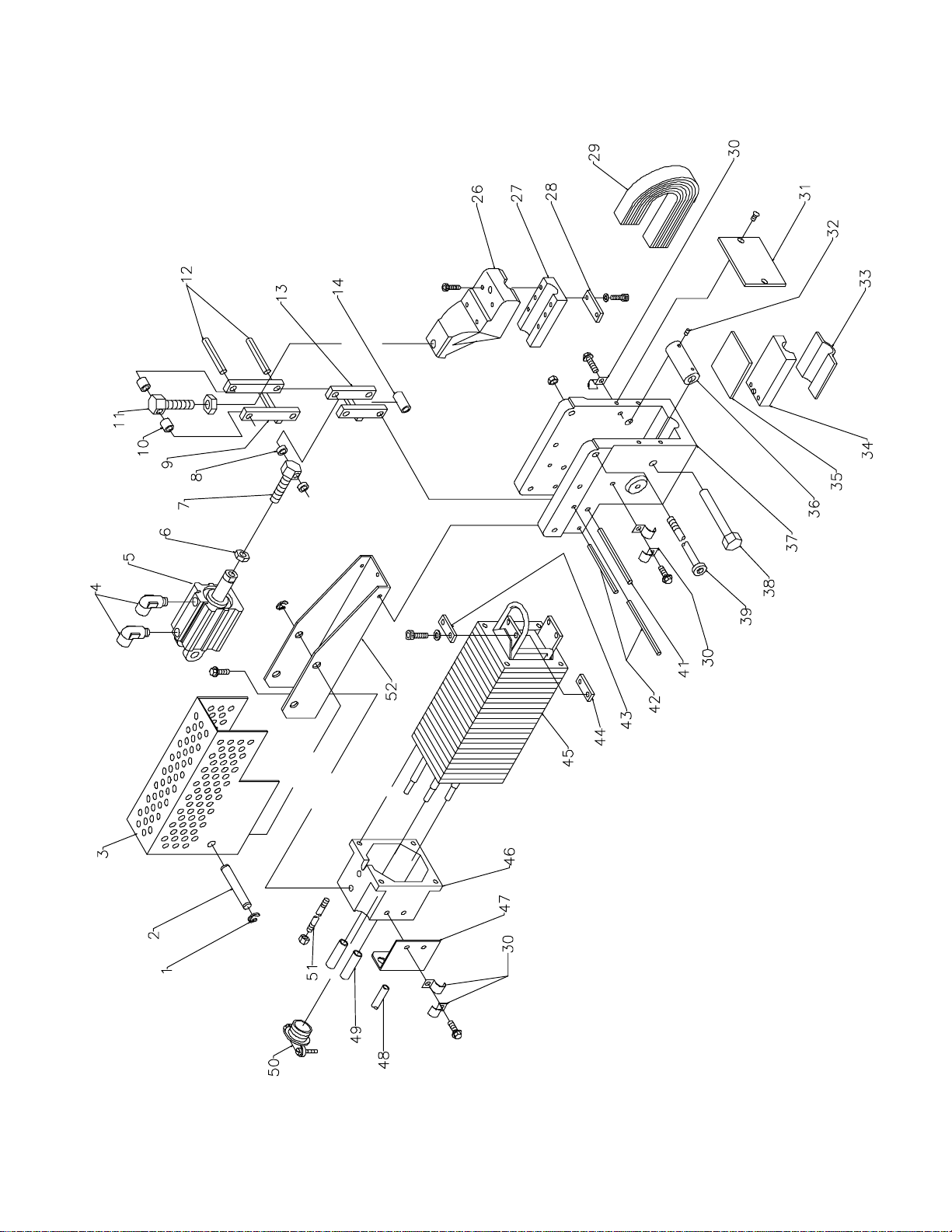
. Hardware is common and
not available unless listed.
OM-745 Page 16
802 774–A
Figure 6-2. Resistance Spot Welder, Air
Page 21

Item
No.
Dia.
Mkgs.
Part
No.
Description
Model SSW-
Figure 6-2. Resistance Spot Welder, Air (Fig 6-1)
1 000 365 RING, rtng ext .390 shaft grv x .042 E 2. . . . . . . . . . . . . . . . . . . . . . . . . . . . . . . . . . . . . . . . . . . . . . . . .
2 110 524 PIN, cylinder air 1. . . . . . . . . . . . . . . . . . . . . . . . . . . . . . . . . . . . . . . . . . . . . . . . . . . . . . . . . . . . . . . . . . . . .
3 198 639 GUARD, spot welder 1. . . . . . . . . . . . . . . . . . . . . . . . . . . . . . . . . . . . . . . . . . . . . . . . . . . . . . . . . . . . . . . .
4 199 115 FITTING, pipe brs 2. . . . . . . . . . . . . . . . . . . . . . . . . . . . . . . . . . . . . . . . . . . . . . . . . . . . . . . . . . . . . . . . . . .
5 199 104 CYLINDER, air 1. . . . . . . . . . . . . . . . . . . . . . . . . . . . . . . . . . . . . . . . . . . . . . . . . . . . . . . . . . . . . . . . . . . . .
6 601 881 NUT, stl hex jam .500-20 3. . . . . . . . . . . . . . . . . . . . . . . . . . . . . . . . . . . . . . . . . . . . . . . . . . . . . . . . . . . . .
7 010 749 SCREW, .500-20 x 1.562hexhd stl 1. . . . . . . . . . . . . . . . . . . . . . . . . . . . . . . . . . . . . . . . . . . . . . . . . . . . .
8 010 748 TUBING, stl .625 OD x 12ga wall x .203 2. . . . . . . . . . . . . . . . . . . . . . . . . . . . . . . . . . . . . . . . . . . . . . . .
9 010 746 LINKAGE, upper 1. . . . . . . . . . . . . . . . . . . . . . . . . . . . . . . . . . . . . . . . . . . . . . . . . . . . . . . . . . . . . . . . . . . .
10 010 736 TUBING, stl .625 OD x 12ga wall x .203 2. . . . . . . . . . . . . . . . . . . . . . . . . . . . . . . . . . . . . . . . . . . . . . .
11 010 726 SCREW, adj pressure 1. . . . . . . . . . . . . . . . . . . . . . . . . . . . . . . . . . . . . . . . . . . . . . . . . . . . . . . . . . . . . . .
12 010 720 PIN, spring CS .375 x 2.750 2. . . . . . . . . . . . . . . . . . . . . . . . . . . . . . . . . . . . . . . . . . . . . . . . . . . . . . . . .
13 010 747 LINKAGE, lower 1. . . . . . . . . . . . . . . . . . . . . . . . . . . . . . . . . . . . . . . . . . . . . . . . . . . . . . . . . . . . . . . . . . .
14 010 738 TUBING, stl .625 OD x 12ga wall x 1.187 1. . . . . . . . . . . . . . . . . . . . . . . . . . . . . . . . . . . . . . . . . . . . . .
26 017 671 HOLDER, tong top 1. . . . . . . . . . . . . . . . . . . . . . . . . . . . . . . . . . . . . . . . . . . . . . . . . . . . . . . . . . . . . . . . .
27 010 723 CLAMP, tong top 1. . . . . . . . . . . . . . . . . . . . . . . . . . . . . . . . . . . . . . . . . . . . . . . . . . . . . . . . . . . . . . . . . . .
28 010 744 BAR, clamping 1. . . . . . . . . . . . . . . . . . . . . . . . . . . . . . . . . . . . . . . . . . . . . . . . . . . . . . . . . . . . . . . . . . . . .
29 010 724 BRAID SET, tong 1. . . . . . . . . . . . . . . . . . . . . . . . . . . . . . . . . . . . . . . . . . . . . . . . . . . . . . . . . . . . . . . . . . .
30 601 117 CLIP, jiffy .500 5. . . . . . . . . . . . . . . . . . . . . . . . . . . . . . . . . . . . . . . . . . . . . . . . . . . . . . . . . . . . . . . . . . . . .
31 110 534 SPLATTER BOARD 1. . . . . . . . . . . . . . . . . . . . . . . . . . . . . . . . . . . . . . . . . . . . . . . . . . . . . . . . . . . . . . . .
32 112 480 SCREW, set .250-28 x .375 cup pt sch stl 2. . . . . . . . . . . . . . . . . . . . . . . . . . . . . . . . . . . . . . . . . . . . .
33 110 530 INSULATION, tong bottom 1. . . . . . . . . . . . . . . . . . . . . . . . . . . . . . . . . . . . . . . . . . . . . . . . . . . . . . . . . .
34 110 529 CLAMP, tong bottom 1. . . . . . . . . . . . . . . . . . . . . . . . . . . . . . . . . . . . . . . . . . . . . . . . . . . . . . . . . . . . . . . .
35 110 533 STRIP, polyest gl .125 x 2.750 x 3.312 1. . . . . . . . . . . . . . . . . . . . . . . . . . . . . . . . . . . . . . . . . . . . . . . .
36 110 536 CAM, tong 1. . . . . . . . . . . . . . . . . . . . . . . . . . . . . . . . . . . . . . . . . . . . . . . . . . . . . . . . . . . . . . . . . . . . . . . .
37 110 903 HOUSING, front transformer 1. . . . . . . . . . . . . . . . . . . . . . . . . . . . . . . . . . . . . . . . . . . . . . . . . . . . . . . . .
38 110 535 CAM, pin tong 1. . . . . . . . . . . . . . . . . . . . . . . . . . . . . . . . . . . . . . . . . . . . . . . . . . . . . . . . . . . . . . . . . . . . .
39 213 081 SCREW, 3/8 x 4-1/2 soc shoulder 1. . . . . . . . . . . . . . . . . . . . . . . . . . . . . . . . . . . . . . . . . . . . . . . . . . . .
40 204 608 NUT, 312-18 .50 hex .34 h stl pld elastic stop nut 2. . . . . . . . . . . . . . . . . . . . . . . . . . . . . . . . . . . . . .
41 602 317 PIN, spring .375 x 4.000 1. . . . . . . . . . . . . . . . . . . . . . . . . . . . . . . . . . . . . . . . . . . . . . . . . . . . . . . . . . . .
42 110 898 PIN, spring .250 x 4.000 2. . . . . . . . . . . . . . . . . . . . . . . . . . . . . . . . . . . . . . . . . . . . . . . . . . . . . . . . . . . .
43 110 531 BAR, tong braid clamping 1. . . . . . . . . . . . . . . . . . . . . . . . . . . . . . . . . . . . . . . . . . . . . . . . . . . . . . . . . . .
44 110 532 BAR, tong braid clamping 1. . . . . . . . . . . . . . . . . . . . . . . . . . . . . . . . . . . . . . . . . . . . . . . . . . . . . . . . . . .
45 T1 121 319 TRANSFORMER, power main (230V) 1. . . . . . . . . . . . . . . . . . . . . . . . . . . . . . . . . . . . . . . . . . . . .
45 T1 121 320 TRANSFORMER, power main (460V) 1. . . . . . . . . . . . . . . . . . . . . . . . . . . . . . . . . . . . . . . . . . . . .
46 110 527 CAP, transformer rear 1. . . . . . . . . . . . . . . . . . . . . . . . . . . . . . . . . . . . . . . . . . . . . . . . . . . . . . . . . . . . . . .
47 010 739 SHIELD, tube coolant 1. . . . . . . . . . . . . . . . . . . . . . . . . . . . . . . . . . . . . . . . . . . . . . . . . . . . . . . . . . . . . . .
48 110 901 TUBING, coolant secondary 1. . . . . . . . . . . . . . . . . . . . . . . . . . . . . . . . . . . . . . . . . . . . . . . . . . . . . . . . .
49 026 834 TUBING, fbr vulc .312 ID x .437 OD 2. . . . . . . . . . . . . . . . . . . . . . . . . . . . . . . . . . . . . . . . . . . . . . . . . .
51 010 034 STUD, .250-28 x 11.000 4. . . . . . . . . . . . . . . . . . . . . . . . . . . . . . . . . . . . . . . . . . . . . . . . . . . . . . . . . . . . .
52 110 539 BRACKET, mtg cylinder air 1. . . . . . . . . . . . . . . . . . . . . . . . . . . . . . . . . . . . . . . . . . . . . . . . . . . . . . . . . .
Quantity
2020ATT
2040ATT
+When ordering a component originally displaying a precautionary label, the label should also be ordered.
To maintain the factory original performance of your equipment, use only Manufacturer’s Suggested
Replacement Parts. Model and serial number required when ordering parts from your local distributor.
OM-745 Page 17
Page 22
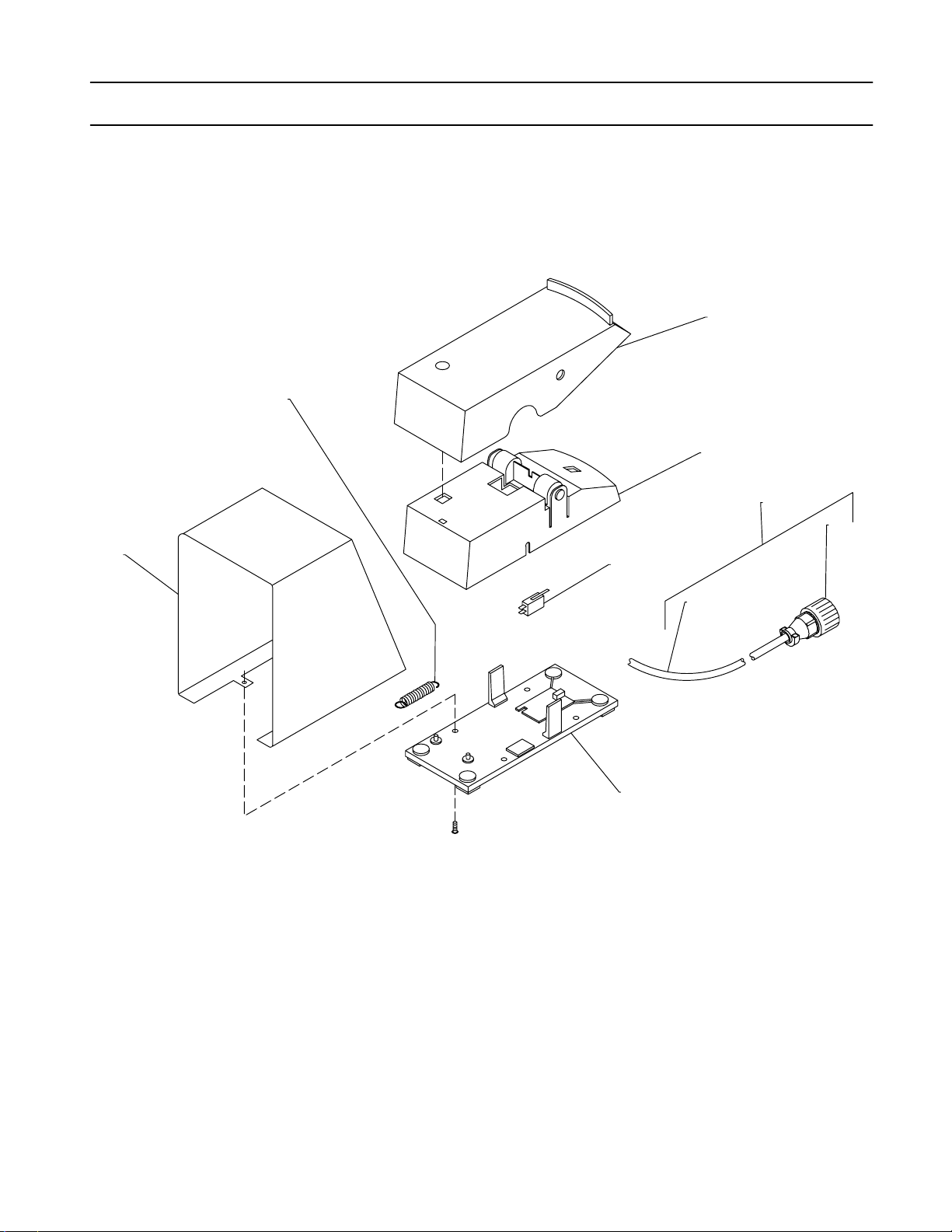
Item
No.
Dia.
Mkgs.
Part
No.
Description
Quantity
Figure 6-3. RFSW-10/20 (Fig 6-1)
1 185 929 PEDAL/HOUSING/BOTTOM PLATE 1. . . . . . . . . . . . . . . . . . . . . . . . . . . . . . . . . . . . . . . . . . . . . . . . . . .
2 S1 183 629 SWITCH, limit 10A 125/250V 1. . . . . . . . . . . . . . . . . . . . . . . . . . . . . . . . . . . . . . . . . . . . . . . . . . . . . . .
3 200 288 CABLE, control (consisting of) 1. . . . . . . . . . . . . . . . . . . . . . . . . . . . . . . . . . . . . . . . . . . . . . . . . . . . . . . . . .
4 605 156 CABLE, port 20ga 5/c ( order by ft) 6ft. . . . . . . . . . . . . . . . . . . . . . . . . . . . . . . . . . . . . . . . . . . . . . . . . . . . .
5 PLG1 079 878 HOUSING PLUG & PINS (service kit) 1. . . . . . . . . . . . . . . . . . . . . . . . . . . . . . . . . . . . . . . . . . . . .
6 187 078 COVER, guard 1. . . . . . . . . . . . . . . . . . . . . . . . . . . . . . . . . . . . . . . . . . . . . . . . . . . . . . . . . . . . . . . . . . . . . . .
7 182 626 SPRING, ext 1. . . . . . . . . . . . . . . . . . . . . . . . . . . . . . . . . . . . . . . . . . . . . . . . . . . . . . . . . . . . . . . . . . . . . . . . .
. Hardware is common and
not available unless listed.
7
1
1
3
5
6
2
4
1
801 931-B
Figure 6-3. RFSW-10/20
To maintain the factory original performance of your equipment, use only Manufacturer’s Suggested
Replacement Parts. Model and serial number required when ordering parts from your local distributor.
OM-745 Page 18
Page 23
Notes
OM-745 Page 19
Page 24
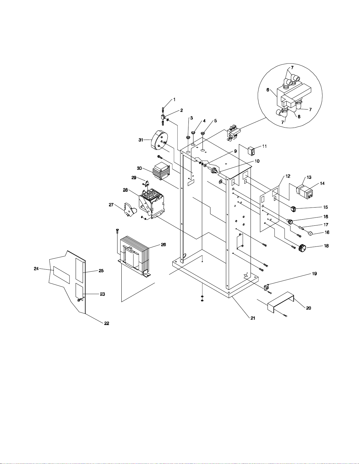
. Hardware is common and
not available unless listed.
OM-745 Page 20
802 765-A
Figure 6-4. Pedestal, Air Operated (SSW Models)
Page 25

Quantity
T
T
I
tem
No.
Dia.
Mkgs.
Part
No.
Description
Model
SSW-
Figure 6-4. Pedestal, Air Operated (Fig 6-1)
1 053 525 FITTING, brs barbed M 5/16tbg x 1/8NPT 2. . . . . . . . . . . . . . . . . . . . . . . . . . . . . . . . . . . . . . . . . . . .
603 105 HOSE, nprn brd No. 1 x .312 ID (order by ft) 2ft. . . . . . . . . . . . . . . . . . . . . . . . . . . . . . . . . . . . . . . . . . . .
010 323 CLAMP, hose .250-.625dia 2. . . . . . . . . . . . . . . . . . . . . . . . . . . . . . . . . . . . . . . . . . . . . . . . . . . . . . . . . . . . .
2 602 965 FITTING, pipe brs tee 1/8NPT 1. . . . . . . . . . . . . . . . . . . . . . . . . . . . . . . . . . . . . . . . . . . . . . . . . . . . . .
3 030 170 BUSHING, snap-in nyl .750 ID x 1.000mtg hole 2. . . . . . . . . . . . . . . . . . . . . . . . . . . . . . . . . . . . . . . .
4 070 371 BLANK, snap-in nyl 1.093 x 1.125mtg hole 1. . . . . . . . . . . . . . . . . . . . . . . . . . . . . . . . . . . . . . . . . . . .
5 057 357 BUSHING, snap-in nyl .937 ID x 1.125mtg hole 1. . . . . . . . . . . . . . . . . . . . . . . . . . . . . . . . . . . . . . . .
6 AS1 199 109 VALVE, 115 VAC 2way (5)1/4 nptf piping ports (consisting of) 1. . . . . . . . . . . . . . . . . . . . . . .
7 199 115 FTG, pipe brs qcon elbow male 1/4 npt 3. . . . . . . . . . . . . . . . . . . . . . . . . . . . . . . . . . . . . . . . . . . . . . .
8 010 678 FTG, pipe brs elbow st 1/4 NPTL 1. . . . . . . . . . . . . . . . . . . . . . . . . . . . . . . . . . . . . . . . . . . . . . . . . . . .
9 602 243 WASHER, flat stl .375 1. . . . . . . . . . . . . . . . . . . . . . . . . . . . . . . . . . . . . . . . . . . . . . . . . . . . . . . . . . . . . .
605 787 WASHER, lock stl intl tooth .500 1. . . . . . . . . . . . . . . . . . . . . . . . . . . . . . . . . . . . . . . . . . . . . . . . . . . . . . . .
010 910 WASHER, flat stl SAE .375 1. . . . . . . . . . . . . . . . . . . . . . . . . . . . . . . . . . . . . . . . . . . . . . . . . . . . . . . . . . . .
10 S5 177 123 SWITCH, pressure oil 4psi NO cont 1. . . . . . . . . . . . . . . . . . . . . . . . . . . . . . . . . . . . . . . . . . . . .
11 S1 198 637 CIRCUIT BREAKER/SWITCH 1 amp lighted 120VAC 1. . . . . . . . . . . . . . . . . . . . . . . . . . . . . .
12 200 264 NAMEPLATE 1. . . . . . . . . . . . . . . . . . . . . . . . . . . . . . . . . . . . . . . . . . . . . . . . . . . . . . . . . . . . . . . . . . . .
13 199 247 SOCKET, relay 11 pin scr term 1. . . . . . . . . . . . . . . . . . . . . . . . . . . . . . . . . . . . . . . . . . . . . . . . . . . . .
14 TD1 198 636 TIMER, digital al 0-9.99 sec 120 VAC 60 Hz cycle timer 1. . . . . . . . . . . . . . . . . . . . . . . . . .
15 S3 196 575 SWITCH, rocker SPST 10A 250VAC on-none-off .250 qc 1. . . . . . . . . . . . . . . . . . . . . . . . . .
16 044 747 HOLDER, fuse crtg 30A 600V 1. . . . . . . . . . . . . . . . . . . . . . . . . . . . . . . . . . . . . . . . . . . . . . . . . . . . . .
17 F1 *128 430 FUSE, crtg 1A 600V 1. . . . . . . . . . . . . . . . . . . . . . . . . . . . . . . . . . . . . . . . . . . . . . . . . . . . . . . . .
18 097 926 KNOB, pointer 1. . . . . . . . . . . . . . . . . . . . . . . . . . . . . . . . . . . . . . . . . . . . . . . . . . . . . . . . . . . . . . . . . . .
19 RC1 048 282 RECEPTACLE w/skts (service kit) 1. . . . . . . . . . . . . . . . . . . . . . . . . . . . . . . . . . . . . . . . . . . . .
20 202 219 GUARD 1. . . . . . . . . . . . . . . . . . . . . . . . . . . . . . . . . . . . . . . . . . . . . . . . . . . . . . . . . . . . . . . . . . . . . . . . .
21 198 635 CABINET, pedestal 1. . . . . . . . . . . . . . . . . . . . . . . . . . . . . . . . . . . . . . . . . . . . . . . . . . . . . . . . . . . . . . .
22 +110 551 PANEL, side pedestal 1. . . . . . . . . . . . . . . . . . . . . . . . . . . . . . . . . . . . . . . . . . . . . . . . . . . . . . . . . . . .
23 201 063 LABEL, warning electric shock can kill, install 1. . . . . . . . . . . . . . . . . . . . . . . . . . . . . . . . . . . . . . . .
24 193 776 LABEL, MILLER 6.093 x 2.593 horizontal 1. . . . . . . . . . . . . . . . . . . . . . . . . . . . . . . . . . . . . . . . . . . .
25 143 140 LABEL, warning general precautionary 1. . . . . . . . . . . . . . . . . . . . . . . . . . . . . . . . . . . . . . . . . . . . . .
26 Z 199 200 REACTOR, (230V) 1. . . . . . . . . . . . . . . . . . . . . . . . . . . . . . . . . . . . . . . . . . . . . . . . . . . . . . . . . . . .
26 Z 199 201 REACTOR, (460V) 1. . . . . . . . . . . . . . . . . . . . . . . . . . . . . . . . . . . . . . . . . . . . . . . . . . . . . . . . . . . .
27 W1 213 446 INTERLOCK, cntor NO size 3-1/2 1. . . . . . . . . . . . . . . . . . . . . . . . . . . . . . . . . . . . . . . . . . . . .
28 W 034 909 CONTACTOR, 4P 115/230V (consisting of) 1. . . . . . . . . . . . . . . . . . . . . . . . . . . . . . . . . . . . . . .
034 910 COIL 1. . . . . . . . . . . . . . . . . . . . . . . . . . . . . . . . . . . . . . . . . . . . . . . . . . . . . . . . . . . . . . . . . . . . . . . . . . . . . . . .
*034 911 KIT, point 4. . . . . . . . . . . . . . . . . . . . . . . . . . . . . . . . . . . . . . . . . . . . . . . . . . . . . . . . . . . . . . . . . . . . . . . . . . .
29 035 049 LINK, connecting contactor term 4. . . . . . . . . . . . . . . . . . . . . . . . . . . . . . . . . . . . . . . . . . . . . . . . . . . .
30 T2 202 208 TRANSFORMER, control 100VA 230/460V 1. . . . . . . . . . . . . . . . . . . . . . . . . . . . . . . . . . . . . .
31 S2 011 632 SWITCH, rotary 10 pos 50A 300V 1. . . . . . . . . . . . . . . . . . . . . . . . . . . . . . . . . . . . . . . . . . . . . .
2020AT
2040AT
*Recommended Spare Parts.
+When ordering a component originally displaying a precautionary label, the label should also be ordered.
To maintain the factory original performance of your equipment, use only Manufacturer’s Suggested
Replacement Parts. Model and serial number required when ordering parts from your local distributor.
OM-745 Page 21
Page 26
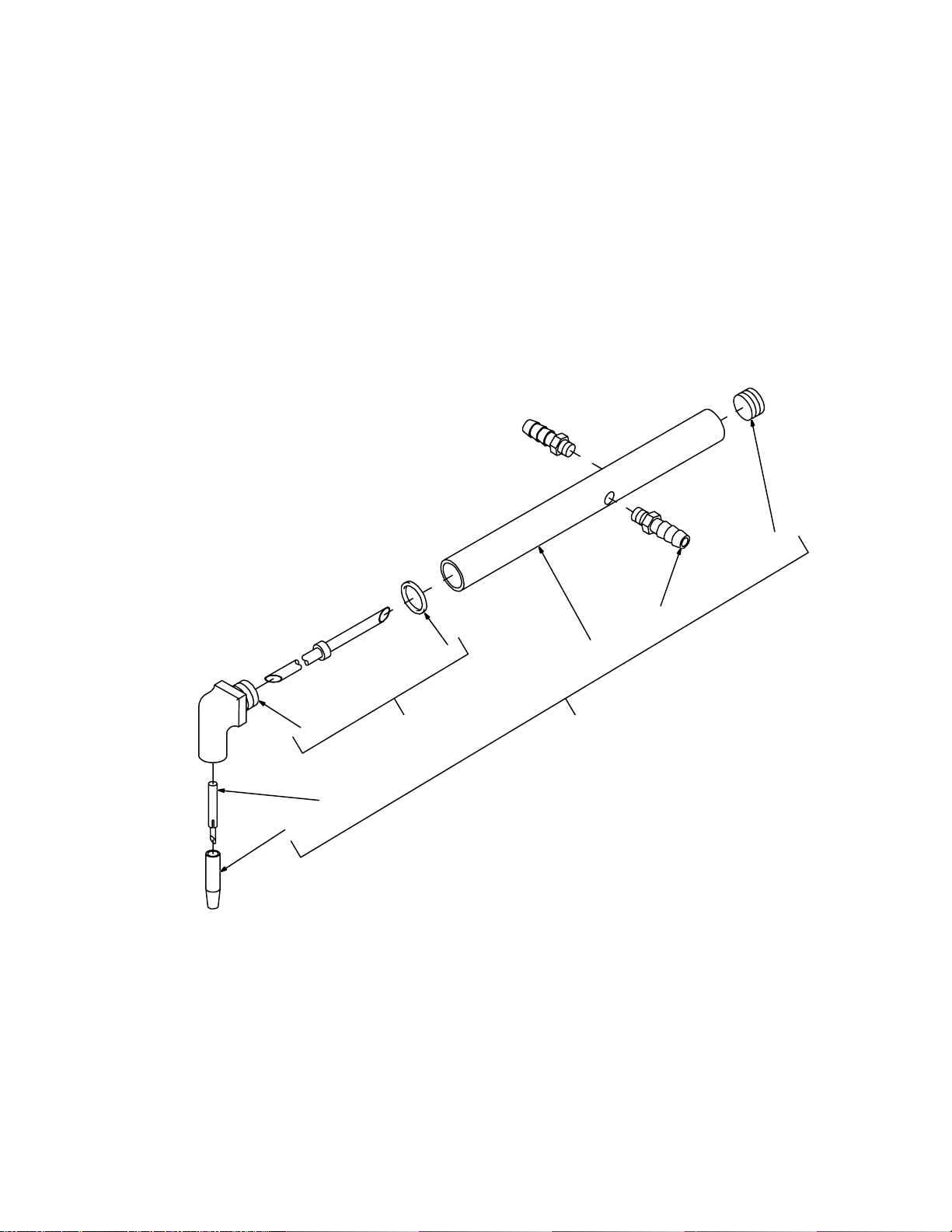
. Hardware is common and
not available unless listed.
9
8
6
4
5
3
2
7
1
027 777-A
OM-745 Page 22
Figure 6-5. Tongs
Page 27

Quantity
Item
No.
Part
No.
Description
Holder
45 or 90
Deg
No. 1 Morse Taper No. 2 Morse Taper
6” 12” 18” 6” 12” 18”
Figure 6-6. Tongs (Optional)
1 027 778 TONG, 6 in (consisting of) 90 deg 2. . . . . . . . . . . . . . . . . . . . . .
1 027 777 TONG, 12 in (consisting of) 90 deg 2. . . . . . . . . . . . . . . . . . . . . . . . . . . .
1 027 776 TONG, 18 in (consisting of) 90 deg 2. . . . . . . . . . . . . . . . . . . . . . . . . . . . . . . . . . .
1 027 781 TONG, 12 in (consisting of) 90 deg 2. . . . . . . . . . . . . . . . . . . . . . . . . . . . . . . . . . . . . . . . . . . . . .
1 027 780 TONG, 18 in (consisting of) 90 deg 2. . . . . . . . . . . . . . . . . . . . . . . . . . . . . . . . . . . . . . . . . . . . . . . . . . . . .
1 027 770 TONG, 6 in (consisting of) 45 deg 2. . . . . . . . . . . . . . . . . . . . . .
1 027 769 TONG, 12 in (consisting of) 45 deg 2. . . . . . . . . . . . . . . . . . . . . . . . . . . .
1 027 768 TONG, 18 in (consisting of) 45 deg 2. . . . . . . . . . . . . . . . . . . . . . . . . . . . . . . . . . .
1 027 774 TONG, 6 in (consisting of) 45 deg 2. . . . . . . . . . . . . . . . . . . . . . . . . . . . . . . . . . . . . . . . .
1 027 772 TONG, 18 in (consisting of) 45 deg 2. . . . . . . . . . . . . . . . . . . . . . . . . . . . . . . . . . . . . . . . . . . . . . . . . . . . .
2 TIPS, (see chart). . . . . . . . . . . . .
3 010 755 TUBE, telescoping 90 deg 1 1 1 1 1. . . . . . . . . . . . . . . . . . . . . . . . . . . . . . . . . . . . . . . . . . . . . . . . . .
3 031 554 TUBE, telescoping 45 deg 1 1 1 1 1. . . . . . . . . . . . . . . . . . . . . . . . . . . . . . . . . . . . . . . . . . . . . . . . . .
4 010 501 TUBE ASSEMBLY, tong (consisting of) 90 deg 1. . . . . . . . . . .
4 010 502 TUBE ASSEMBLY, tong (consisting of) 90 deg 1. . . . . . . . . . . . . . . . . .
4 010 503 TUBE ASSEMBLY, tong (consisting of) 90 deg 1. . . . . . . . . . . . . . . . . . . . . . . . .
4 027 758 TUBE ASSEMBLY, tong (consisting of) 90 deg 1. . . . . . . . . . . . . . . . . . . . . . . . . . . . . .
4 027 757 TUBE ASSEMBLY, tong (consisting of) 90 deg 1. . . . . . . . . . . . . . . . . . . . . . . . . . . . . . . . . . . .
4 027 756 TUBE ASSEMBLY, tong (consisting of) 90 deg 1. . . . . . . . . . . . . . . . . . . . . . . . . . . . . . . . . . . . . . . . . . .
4 027 766 TUBE ASSEMBLY, tong (consisting of) 45 deg 1. . . . . . . . . . .
4 027 765 TUBE ASSEMBLY, tong (consisting of) 45 deg 1. . . . . . . . . . . . . . . . . .
4 027 764 TUBE ASSEMBLY, tong (consisting of) 45 deg 1. . . . . . . . . . . . . . . . . . . . . . . . .
4 027 762 TUBE ASSEMBLY, tong (consisting of) 45 deg 1. . . . . . . . . . . . . . . . . . . . . . . . . . . . . .
4 027 761 TUBE ASSEMBLY, tong (consisting of) 45 deg 1. . . . . . . . . . . . . . . . . . . . . . . . . . . . . . . . . . . .
4 027 760 TUBE ASSEMBLY, tong (consisting of) 45 deg 1. . . . . . . . . . . . . . . . . . . . . . . . . . . . . . . . . . . . . . . . . . .
5 010 734 HOLDER, tip 90 deg 1 1 1. . . . . . . . . . . . . . . . . . . . . . . . . . . . . . . . . . . . . . . . . . .
5 010 735 HOLDER, tip 90 deg 1 1 1. . . . . . . . . . . . . . . . . . . . . . . . . . . . . . . . . . . . . . . . . . . . . . . . . . . . . . . . . . . .
5 010 753 HOLDER, tip 45 deg 1 1 1. . . . . . . . . . . . . . . . . . . . . . . . . . . . . . . . . . . . . . . . . . .
5 010 754 HOLDER, tip 45 deg 1 1 1. . . . . . . . . . . . . . . . . . . . . . . . . . . . . . . . . . . . . . . . . . . . . . . . . . . . . . . . . . . .
6 603 090 O-RING, .625 ID x .812 OD All 1 1 1 1 1 1. . . . . . . . . . . . . . . . . . . . . . . . . . . . . . . . . . . . . . . . . . .
7 010 498 TUBE, connecting 6 in tong All 1 1. . . . . . . . . . . . . . . . . . . . . . . . . . . . . . . . . . . . . . . . .
7 010 499 TUBE, connecting 12 in tong All 1 1. . . . . . . . . . . . . . . . . . . . . . . . . . . . . . . . . . . . . . . . . . . . . . .
7 010 500 TUBE, connecting 18 in tong All 1 1. . . . . . . . . . . . . . . . . . . . . . . . . . . . . . . . . . . . . . . . . . . . . . . . . . . . .
8 053 525 FITTING, brs-barbed M. . . . . .
5/16tbg x 1/8NPT All 2 2 2 2 2 2. . . . . . . . . . . . . . . . . . . . . . . . . . . . . . . . . . . . . . . . . . . . . .
9 010 758 FITTING, pipe brs skt hd 3/8NPT All 1 1 1 1 1 1. . . . . . . . . . . . . . . . . . . . . . . . . . . . . . . . . . . . . .
To maintain the factory original performance of your equipment, use only Manufacturer’s Suggested
Replacement Parts. Model and serial number required when ordering parts from your local distributor.
OM-745 Page 23
Page 28
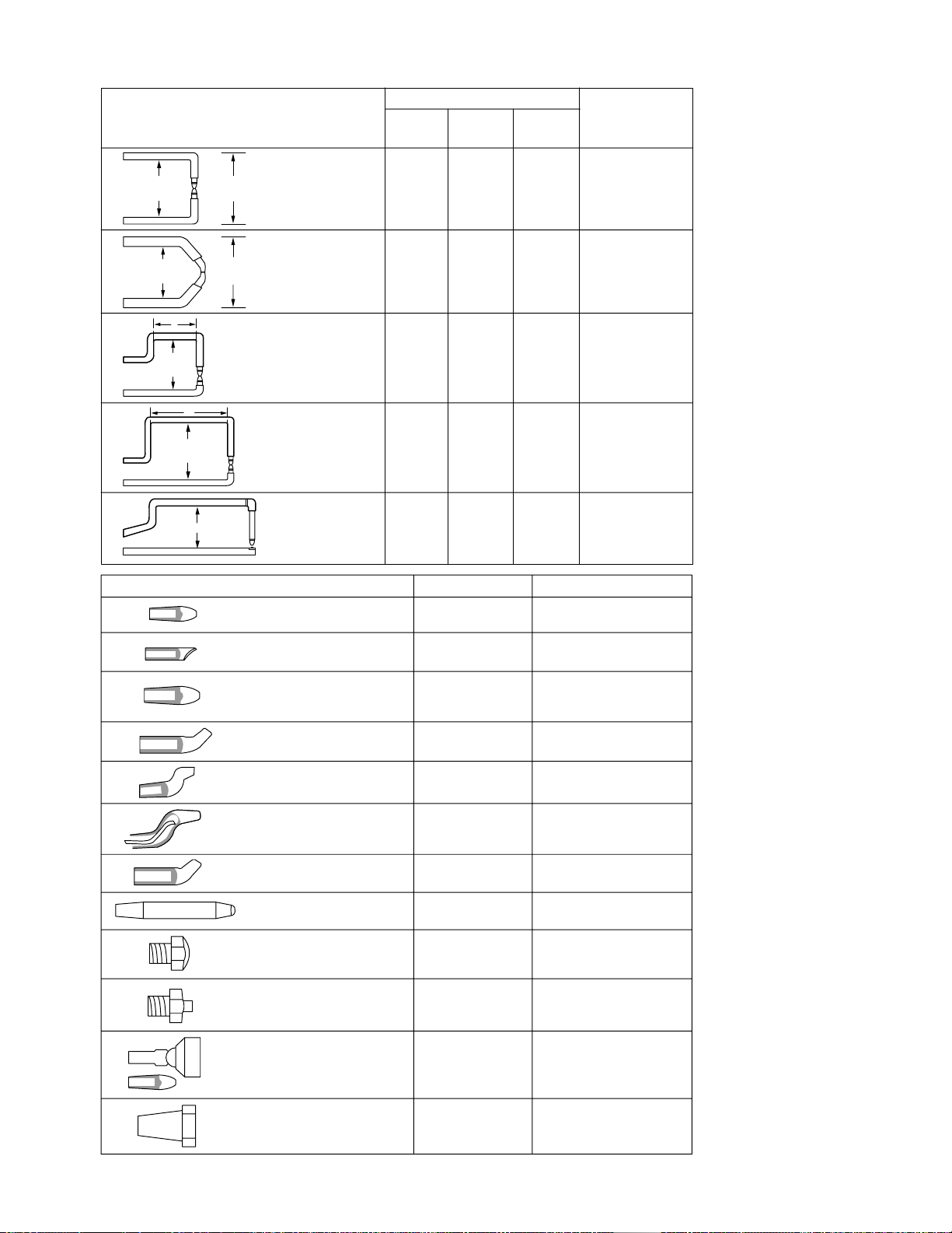
Tongs and Tips (Must be ordered separately from spot welders. One pair of tips are supplied with each set of tongs.)
4–1/4 in
(108 mm)
4–1/4 in
(108 mm)
X
7–1/2 in
(1
90 mm)
(229 mm)
4–1/4 in (108 mm)
9 in
X
TONGS
6–1/4 in
(159 mm)
6–1/4 in
(159 mm)
STANDA RD 90°
No. 1 Morse Taper
No. 2 Morse Taper
STANDA RD 45°
No. 1 Morse Taper
No. 2 Morse Taper
TT–6W
No. 2 Morse Taper
TT–9W
No. 2 Morse Taper
SW–12
TONG LENGTH
6 in
(150 mm)
#040 218 #040 219 #040 220
––
–
––
–
––
––
12 in
(304 mm)
#041 004 #041 005
–
#071 465
18 in
(457 mm)
#041 001
#040 296
#041 838 #040 308
#041 840
TIPS INCLUDED
#040 223
#040 308
#040 851
#040 225
#040 308
No. 1 P ointed
#071 466
Flat Threaded
#071 467
Top
Bottom
Notes for tongs and ti ps:
.
Tongs and tips shown to the
left can be used with all PSW
and SSW model spot welders.
Recommended max. tong
length is 18 in (457 mm).
.
Tong throat–height dimension
for standard 90 and 45 tongs
is 4–1/4 in
length is measured from the
(108 mm). Throat
center of the spot tips to the
front water hose connection.
X = tong length.
.
One set of tips is supplied with
each set of tongs.
.
Tips are made of RWMA Class
2 alloy .
.
Maximum welding capabilities
are obtained with minimum
tong length.
.
MT= Morse Taper.
.
No. 1 Morse Taper has smaller
diameter than No. 2 Morse
Taper.
No. 1 MT (Pointed)
#040 223
No. 1 M T ( Off set)
#040 224
No. 2 MT (Pointed)
#040 308
No. 1 M T ( Off set)
#040 851
No. 1 M T ( Off set)
#040 226
No. 1 M T ( Off set)
#040 298
No. 2 M T ( Off set)
#040 225
No. 1 MT (Pointed)
#071 466
Threaded (Flat)
#071 343
Threaded (Flat)
#071 467
QUANTITYTIPS
2 tips
2 tips
2 tips
2 tips
2 tips
2 tips
2 tips
1 tip for top tong
1 tip f or bottom tong
1 tip f or bottom tong
WHERE USED
Standard No. 1 Tongs, 90°
Standard No. 1 Tongs, 90°
Standard No. 2 Tongs, 90°
TT–6W Tongs
TT–9W Tongs
Standard No. 1 Tongs, 45°
Standard No. 1 Tongs, 90°
Standard No. 1 Tongs, 90°
Standard No. 2 Tongs, 45°
SW–12 Tong
SW–12 Tong (optional)
SW–12 Tong
OM-745 Page 24
No. 1 MT (Flat Swive l Tip)
Matching Pointed Tip
#040 216
Adapter (adapts No. 1 Morse Taper Tip
to No . 2 recep tacle)
#040 227
2 tips
2 adapters
Standard No. 1 Tongs, 90°
Standard No. 2 Tongs, 90°
TT–6W Tongs (top)
TT–9W Tongs (top)
Page 29

Page 30

Page 31

Warranty Questions?
Call
1-800-4-A-MILLER
for your local
Miller distributor.
Y our distributor also gives
you ...
Service
Y ou always get the fast,
reliable response you
need. Most replacement
parts can be in your
hands in 24 hours.
Support
Need fast answers to the
tough welding questions?
Contact your distributor.
The expertise of the
distributor and Miller is
there to help you, every
step of the way.
Effective January 1, 2002
(Equipment with a serial number preface of “LC” or newer)
This limited warranty supersedes all previous Miller warranties and is exclusive with no other
LIMITED WARRANTY – Subject to the terms and conditions
below, Miller Electric Mfg. Co., Appleton, Wisconsin, warrants
to its original retail purchaser that new Miller equipment sold
after the effective date of this limited warranty is free of defects
in material and workmanship at the time it is shipped by Miller.
THIS WARRANTY IS EXPRESSLY IN LIEU OF ALL OTHER
WARRANTIES, EXPRESS OR IMPLIED, INCLUDING THE
WARRANTIES OF MERCHANTABILITY AND FITNESS.
Within the warranty periods listed below, Miller will repair or
replace any warranted parts or components that fail due to
such defects in material or workmanship. Miller must be
notified in writing within thirty (30) days of such defect or
failure, at which time Miller will provide instructions on the
warranty claim procedures to be followed.
Miller shall honor warranty claims on warranted equipment
listed below in the event of such a failure within the warranty
time periods. All warranty time periods start on the date that
the equipment was delivered to the original retail purchaser, or
one year after the equipment is sent to a North American
distributor or eighteen months after the equipment is sent to an
International distributor.
1. 5 Years Parts – 3 Years Labor
* Original main power rectifiers
* Inverters (input and output rectifiers only)
2. 3 Years — Parts and Labor
* Transformer/Rectifier Power Sources
* Plasma Arc Cutting Power Sources
* Semi-Automatic and Automatic Wire Feeders
* Inverter Power Supplies
* Intellitig
* Engine Driven Welding Generators
(NOTE: Engines are warranted separately by
the engine manufacturer .)
3. 1 Year — Parts and Labor Unless Specified
* DS-2 Wire Feeder
* Motor Driven Guns (w/exception of Spoolmate
Spoolguns)
* Process Controllers
* Positioners and Controllers
* Automatic Motion Devices
* RFCS Foot Controls
* Induction Heating Power Sources
* Water Coolant Systems
* Flowgauge and Flowmeter Regulators (No Labor)
* HF Units
* Grids
* Maxstar 85, 140
* Spot Welders
* Load Banks
* Racks
* Running Gear/Trailers
* Plasma Cutting Torches (except APT & SAF
Models)
* Field Options
(NOTE: Field options are covered under True
Blue for the remaining warranty period of the
product they are installed in, or for a minimum of
one year — whichever is greater.)
4. 6 Months — Batteries
5. 90 Days — Parts
* MIG Guns/TIG Torches
* Induction Heating Coils and Blankets
guarantees or warranties expressed or implied.
* APT, ZIPCUT & PLAZCUT Model Plasma Cutting
Torches
* Remote Controls
* Accessory Kits
* Replacement Parts (No labor)
* Spoolmate Spoolguns
* Canvas Covers
Miller’s True Blue Limited Warranty shall not apply to:
1. Consumable components; such as contact tips,
cutting nozzles, contactors, brushes, slip rings,
relays or parts that fail due to normal wear.
(Exception: brushes, slip rings, and relays are
covered on B o b cat, Trailblazer, and Legend models.)
2. Items furnished by Miller, but manufactured by others,
such as engines or trade accessories. These items are
covered by the manufacturer’s warranty, if any.
3. Equipment that has been modified by any party other
than Miller, or equipment that has been improperly
installed, improperly operated or misused based upon
industry standards, or equipment which has not had
reasonable and necessary maintenance, or equipment
which has been used for operation outside of the
specifications for the equipment.
MILLER PRODUCTS ARE INTENDED FOR PURCHASE
AND USE BY COMMERCIAL/INDUSTRIAL USERS AND
PERSONS TRAINED AND EXPERIENCED IN THE USE
AND MAINTENANCE OF WELDING EQUIPMENT.
In the event of a warranty claim covered by this warranty, the
exclusive remedies shall be, at Miller’s option: (1) repair; or (2)
replacement; or, where authorized in writing by Miller in
appropriate cases, (3) the reasonable cost of repair or
replacement at an authorized Miller service station; or (4)
payment of or credit for the purchase price (less reasonable
depreciation bas e d u p o n a c tual use) upon return of the goods
at customer’s risk and expense. Miller’s option of repair or
replacement will be F.O.B., Factory at Appleton, Wisconsin, or
F.O.B. at a Miller authorized service facility as determined by
Miller. Therefore no compensation or reimbursement for
transportation costs of any kind will be allowed.
TO THE EXTENT PERMITTED BY LAW, THE REMEDIES
PROVIDED HEREIN ARE THE SOLE AND EXCLUSIVE
REMEDIES. I N N O EVENT SHALL MILLER BE LIABLE FOR
DIRECT, INDIRECT, SPECIAL, INCIDENTAL OR
CONSEQUENTIAL DAMAGES (INCLUDING LOSS OF
PROFIT), WHETHER BASED ON CONTRACT, TORT OR
ANY OTHER LEGAL THEORY.
ANY EXPRESS WARRANTY NOT PROVIDED HEREIN
AND ANY IMPLIED WARRANTY, GUARANTY OR
REPRESENTATION AS TO PERFORMANCE, AND ANY
REMEDY FOR BREACH OF CONTRACT TORT OR ANY
OTHER LEGAL THEORY WHICH, BUT FOR THIS
PROVISION, MIGHT ARISE BY IMPLICATION,
OPERATION OF LAW, CUSTOM OF TRADE OR COURSE
OF DEALING, INCLUDING ANY IMPLIED WARRANTY OF
MERCHANTABILITY OR FITNESS FOR PARTICULAR
PURPOSE, WITH RESPECT TO ANY AND ALL
EQUIPMENT FURNISHED BY MILLER IS EXCLUDED AND
DISCLAIMED BY MILLER.
Some states in the U.S.A. do not allow limitations of how long
an implied warranty lasts, or the exclusion of incidental,
indirect, special or consequential damages, so the above
limitation or exclusion may not apply to you. This warranty
provides specific legal rights, and other rights may be
available, but may vary from state to state.
In Canada, legislation in some provinces provides for certain
additional warranties or remedies other than as stated herein,
and to the extent that they may not be waived, the limitations
and exclusions set out above may not apply. This Limited
Warranty provides specific legal rights, and other rights may
be available, but may vary from province to province.
miller_warr 6/02
Page 32
Owner’s Record
Please complete and retain with your personal records.
Model Name Serial/Style Number
Purchase Date (Date which equipment was delivered to original customer.)
Distributor
Address
City
State Zip
For Service
Call 1-800-4-A-Miller or see our website at www.MillerWelds.com
to locate a DISTRIBUTOR or SERVICE AGENCY near you.
Always provide Model Name and Serial/Style Number.
Contact your Distributor for:
Welding Supplies and Consumables
Options and Accessories
Personal Safety Equipment
Service and Repair
Replacement Parts
Training (Schools, Videos, Books)
Technical Manuals (Servicing Information
and Parts)
Circuit Diagrams
Welding Process Handbooks
Miller Electric Mfg. Co.
An Ill inoi s Tool Works Company
1635 West Spencer Street
Appleton, WI 54914 USA
International Headquarters–USA
USA Phone: 920-735-4505 Auto-A t t ended
USA & Canada FAX: 920-735-4134
International FAX: 920-735-4125
European Headquarters –
United Kingdom
Phone: 44 (0) 1204-593493
FAX: 44 (0) 1204-598066
www.MillerWelds.com
Contact the Delivering Carrier for:
For assistance in filing or settling claims,
contact your distributor and/or equipment
manufacturer’s Transportation Department.
PRINTED IN USA 2002 Miller Electric Mfg. Co. 5/02
File a claim for loss or damage during
shipment.
 Loading...