

Page 1
Tripod Series
OPERATOR’S
MANUAL
#1630 - Solo 75 2-Stage Tripod (Alloy)
#1501 - Solo 75 2-Stage Tripod
#2001 - Solo 75 3-Stage Tripod
#1505 - Solo 100 3-Stage Tripod
Page 2
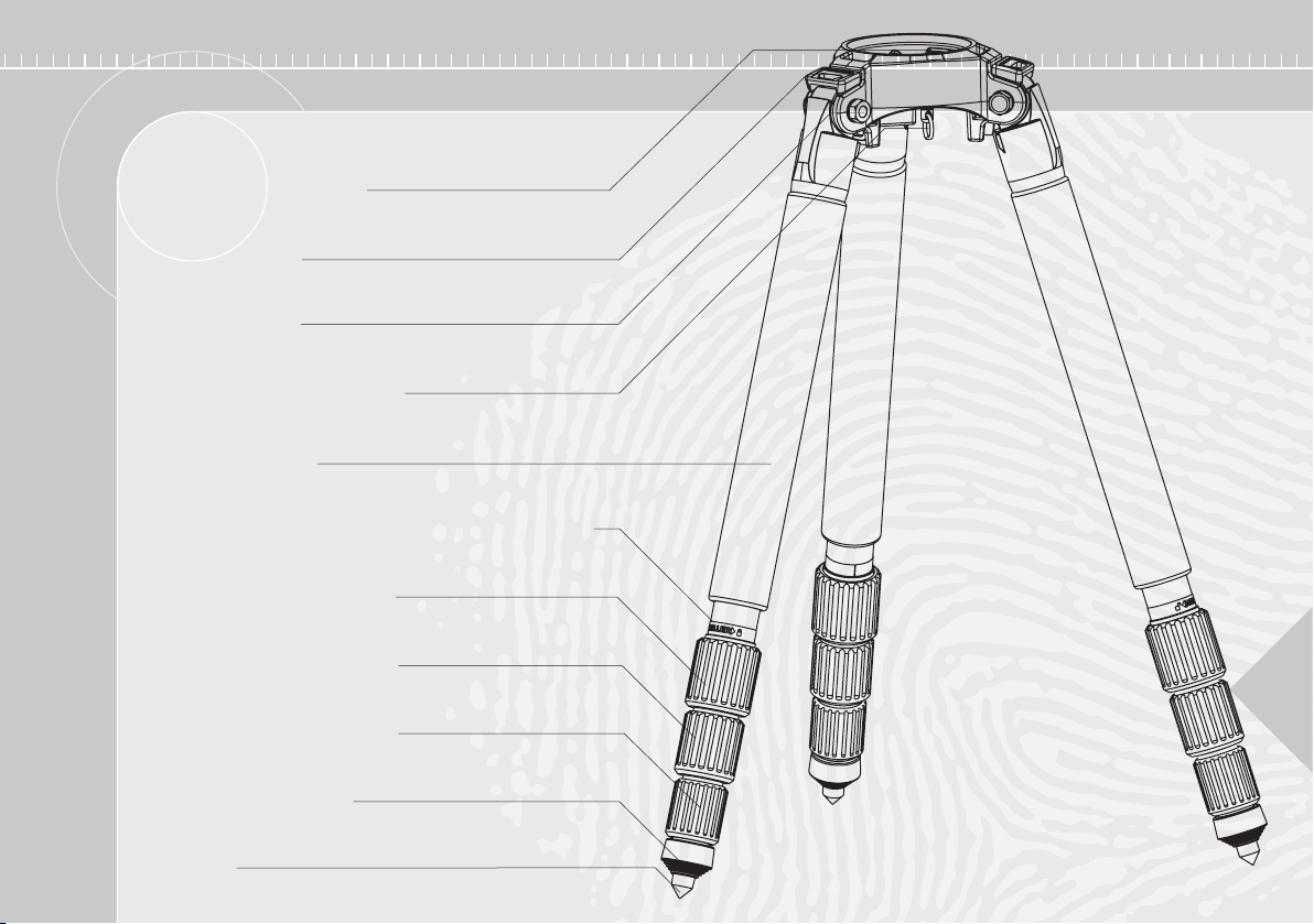
Features and Controls
75mm Bowl or 100mm Bowl
Leg Angle Adjuster
Leg Mounting Bolt
Shoulder Strap Mounting Point
Protective Leg Cover
Leg Lock Direction Label (also leg strap mounting point)
Upper Concentric RAPID LOCK
Middle Concentric RAPID LOCK
Lower Concentric RAPID LOCK
Screw Down Rubber Foot
2
Steel Spike
Page 3
Introduction
Operation Manual
Thank you for purchasing the Miller SOLO
RAPID LOCK
SOLO
standard 75 & 100 mm ball levelling pan & tilt heads. SOLO
is designed to support DVCAM camcorders in location and studio
production.
The quality of design, manufacture and finishing of the SOLO RAPID LOCK
tripod has proven to deliver strength, lightweight, durability and versatility.
The Carbon Fibre/Basalt tubing provides optimum rigidity while the SOLO
RAPID LOCK
enable a fast, accurate and hassle free set-up of the tripod. Importantly,
the high strength and stability of the SOLO
maintained throughout its impressive operating height range, from a low
22 cm (8.7”) up to an impressive 187 cm (73”) (#1505 & #2001 SOLO
tripod).
LOCK
is a professional tripod, compatible with industry
system and the centrally located Leg Angle Adjustors
RAPID LOCK
RAPID LOCK
tripod.
RAPID LOCK
tripod is
RAPID
The operating instructions are described
in five steps. Please read and understand
these instructions before using this
equipment. Do Not omit any steps.
This Operator’s Manual contains
important set-up, pull-down, adjustment, safety and maintenance information for the SOLO RAPID LOCK tripod.
Please consult the Operator’s Manual for the
Fluid Head, Camera and/or Accessories to
ensure compatibility and safety of the system.
Technical Data
Cat# 1630 1501 2001 1505
Bowl Diameter 75mm 75mm 75mm 100mm
Tube Configuration 2 Stage telescopic 2 Stage telescopic 3 Stage telescopic 3 Stage telescopic
Lock Type Concentric Rapid Lock Concentric Rapid Lock Concentric Rapid Lock Concentric Rapid Lock
Tube Material Alloy Carbon fibre/Basalt Carbon fibre/Basalt Carbon fibre/Basalt
Payload Capacity kg (lb) 20 (44.1) 20 (44.1) 20 (44.1) 30 (66)
Weight kg (lb) 2.9 (6.4) 2.5 (5.5) 3.0 (6.6) 3.1 (6.8)
Max Height mm (in) 1625 (64) 1614 (63.5) 1870 (73.6) 1870 (73.6)
Min Height mm (in) 234 (9.2) 234 (9.2) 220 (8.7) 220 (8.7)
Transport Length mm (in) 700 (27.6) 694 (27.3) 658 (25.9) 658 (25.9)
3
Page 4

Tripod Setup
Fig 3 Leg angle adjuster
raised
Fig 1 Collapsed
Fig 2 Spread
4
position
position
Remove tripod from carry bag, undo clip on leg strap and
stand on a level surface (if possible). Depending on
surface, screw out rubber foot for non-scratch contact
to interior or hard surfaces or screw in for a spike on
exterior soft surfaces such as dirt or sand.
Note: Leg angle adjusters are spring loaded and self
adjusting. Do not hold leg angle adjuster up while spreading
tripod legs as this may cause leg angle adjusters to operate
improperly and potentially damage the tripod.
Maximum Height
(Leg angle adjustment is not required)
1 Separate legs slightly so they are
parallel.
2 Working with each leg
individually, grip concentric locks
and release one turn (see leg
lock direction label on leg).
3 Extend to desired length and
turn each concentric lock to
engage firmly. Repeat process
for remaining legs.
4 Spread tripod legs (Fig. 2)
and adjust leg length to
ensure tripod bowl is
approximately level.
5 Level the fluid head using bubble level and ball
levelling feature of fluid head.
Minimum Height
Note: It is recommended that
minimum height position is used only
with legs at their shortest length.
1 Pull up leg angle adjuster until it locks into a raised
position (Fig. 3). Repeat for all three locks.
2 Holding one leg on the ground pull the remaining two
outward, spreading the tripod to its lowest position. Leg
angle adjuster will automatically engage the leg to hold
the tripod at its lowest height position (Fig. 4).
Fig 4 Lowest height
position
Page 5

Tripod Setup (cont) Tripod Pull Down
Mid Position
Note: This refers to the mid leg
angle position, not necessarily the
height of the tripod.
The SOLO RAPID LOCK tripod has three
leg angle positions. The middle leg angle
position (Fig.7) is self-engaging after
closing leg from fully spread position
(Fig.6). The mid position is chosen for
optimum stability in the 50-130cm tripod
height range, but is not recommended if
the tripod is being used in a crowded
situation, due to the
wide diameter, or
footprint spread, of the
extended tripod.
Fig 5 Leg angle adjuster
raised
Fig 6 Spread Position
1 Remove camera from fluid head.
2 Close the tripod legs so all are pointing
straight down and disengage all
concentric locks.
3 Holding the bowl, lower tripod to its
shortest length and re-engage
concentric locks.
4 Close legs together fully (Fig. 1) fit leg strap and return tripod to
carry bag if finished shooting.
Fig 7 Middle leg
angle position
5
Page 6

Shoulder Strap
Leg Pivot Adjustment
SOLO’s Shoulder Carry Strap can be used looped (both
ends attached to the mounting point on the bowl), to carry
the tripod on one shoulder,
OR
it can be used attached to the bowl and the Leg Strap “D”
ring, to carry the tripod across your back with fluid head
towards the ground.
The leg to bowl pivot joint on the SOLO RAPID LOCK tripod should have
no lateral movement and should swing with a firm, smooth resistance.
As this is a spreader-less tripod, the leg pivot joint requires sufficient
resistance to hold the tripod legs together while being hand carried.
Adjustment is usually not required, however, should it become
necessary, the following procedure must be observed.
1 Lay tripod on a flat surface with legs closed in
transport position.
2 Using 17mm spanner (supplied), gently
tighten nut to achieve firm, smooth movement of
the leg while still having sufficient tension to hold
the legs together when tripod is being hand
carried.
3 Check leg resistance by swinging leg fully open
(using leg angle adjuster) and ensure that all legs
open with a similar degree of effort. Tighten or
loosen bolts as necessary.
Important: Remember not to over-
tighten as this may cause too much
resistance when swinging the legs open.
6
Page 7

Leg Strap
Safety
The Leg Strap is attached to largest diameter leg
tube (as delivered from factory) using ‘hook
and loop’ tape.
The Leg strap also has a “D”
ring attachment point for
the shoulder strap if
required. Check the Leg
Strap periodically to ensure
hook and loop tape is secure.
Maintenance
Regularly inspect tripod for damage or grit. Pay particular
attention to carbon fibre tubes, concentric locks, leg angle
adjusters, condition of bowl, feet and general operation of the
tripod.
Keep grit and dirt out of leg angle adjusters. If leg angle adjusters
or legs grind or stick during operation they may have grit in
contact with their sliding surfaces. The affected parts will require
disassembly and cleaning. Failure to do so may result in
excessive wear and breakage of tripod components.
Regularly clean tripod with a damp rag or soft brush. Wipe off all
sand, dust and salt spray. Do not clean with solvents, cleaning
fluids, lubricants, polishes, abrasives or wire brushes.
Transport and store tripod in Miller bag or case wherever
possible. Store tripod in a dry place, away from direct sunlight.
Read the Operator’s
Manual
Miller recommends that all camera
support equipment should be carried in a
carry bag to reduce the risk of accidental
damage during transport. All Miller SOLO
RAPID LOCK systems include a carry bag to
protect the tripod and reduce exposure to dust
and moisture during transport and storage.
Ensure that the weight of the camera/lens/battery payload
mounted on your tripod does not exceed the recommended
capacity of the fluid head. This will ensure that the tripod and
fluid head you have chosen will operate to their specification.
Note that any offset payload, such as a telephoto lens, will exert
a forward offset load on the support system. Refer to your fluid
head users guide to ensure these loads are properly balanced.
Never set up or pull down a tripod while a camera is mounted on it.
The camera base should be fastened to a suitable camera plate
and tripod plate prior to mounting. The camera should be
attached to the fluid head only after all tripod leg locks are
positively engaged (in locked position) and the tripod is on a
stable surface.
The safe operation of the tripod is the responsibility of the
operator.
7
Page 8

Optional
Service and Sales Support
Cat# Description
#394 Solo Dolly
#1520 Shoulder Strap #1590 Solo Leg Covers (3)
#872 Softcase (padded) #1518 Carry Bag
#876 Softcase (padded) #1521 Transport Strap
#P6005
17mm Spanner
Warranty
Please refer to warranty card for complete details
Website
www.millertripods.com
Miller Authorised Service Agents must carry out all service and repair
work on SOLO RAPID LOCK tripods. Failure to observe this requirement
may void warranty. It is advisable to notify Miller or a Miller Authorised
Service Agent if a change of performance is observed as a result of
impact or rough usage. For information regarding sales and service of
Miller products, or for your nearest Miller representative, please contact
us via our website or at the following:
MILLER CAMERA SUPPORT (Australia)
30 Hotham Parade, Artarmon, Sydney
NSW 2064 Australia
Tel: +61 2 9439 6377
Fax: +61 2 9438 2819
Email: sales@miller.com.au
MILLER FLUID HEADS (Europe) Ltd
Unit 12A, Shepperton Business Park,
Govett Avenue, Shepperton,
Middlesex TW17 8BA, United Kingdom
Tel: +44(0) 1932 222 888
Fax:+44(0) 1932 222 211
Email: sales@millertripods-europe.com
MILLER CAMERA SUPPORT LLC (USA)
216 Little Falls Road (Unit 15 & 16),
Cedar Grove,
New Jersey 07009 USA
Tel: (973) 857 8300
Fax: (973) 857 8188
Email: sales@millertripods.us
D9158-1
 Loading...