

Miller RACSWY050N, RACSWY050C, RACDTA-5K/6FT, RACDTA-5K12/6FT, RACSWY2SBA User Instruction Manual
...Page 1
Page 2

Table of Contents
1.0 General Requirements, Warnings and Limitations............................. 3-4
2.0 Purpose................................................................................................4
3.0 Warnings and Limitations...................................................................4-5
3.1 Compatibility Limitations
4.0 Drop Through Anchor............................................................................6
5.0 Zinc Plated Swivel Anchor....................................................................7
6.0 Stainless Steel Swivel Anchors...........................................................10
7.0 Zinc Plated Swivel Anchors.................................................................14
8.0 Hybrid Concrete Anchor......................................................................19
Product Labels................................................................................... 48
Inspection and Maintenance Log....................................................... 51
Table des Matières
1.0 Exigences Générales, Avertissements et Limitations......................... 15-16
2.0 Compatibilité du Système................................................................... 16
2.1 Groupes de Produits Miller Fall Protection
3.0 Installation des Connecteurs D’ancrage............................................. 17-25
3.1 Ancrage à anneau en D (410)
3.2 Ancrage à boulon en D (415, 416/417, 416SS/417SS, 418/419, 418SS/419SS)
3.3 Ancrage à boulon en D pour béton (417C)
4.0 Inspection et Entretien....................................................................... 26
Étiquettes de Produit.......................................................................... 39
Registre D’inspection et D’entretien................................................... 40
Índice
1.0 Requisitos Generales, Advertencias y Limitaciones.......................... 27-28
2.0 Compatibilidad del Sistema............................................................... 28
2.1 Grupos de Productos Anticaídas Miller
3.0 Instalación de los Conectores de Anclaje.......................................... 29-37
3.1 Ancla de argolla “D” montada (410)
3.2 Ancla “D” de perno (415, 416/417, 416SS/417SS, 418/419, 418SS/419SS)
3.3 Ancla “D” de perno (417C)
4.0 Inspección y Mantenimiento.............................................................. 38
Etiquetas del Producto....................................................................... 39
Registro de Inspección y Mantenimiento........................................... 40
2
Page 3

User Instructions - English
Thank You
Thank you for your purchase of Miller fall protection equipment manufactured by Honeywell
Safety Products. Miller brand products are produced to meet the highest standards of quality at
our ISO 9001 certi ed facility. Miller equipment will provide you with years of use when cared for
properly.
WARNING
All persons using this equipment must read, understand and follow
all instructions. Failure to do so may result in serious injury or death.
Do not use this equipment unless you are properly trained.
Questions?
It is crucial that the authorized person/user of this equipment read and understand these instructions. In addition, federal law requires employers to ensure that all users are trained in the
proper installation, use, inspection, and maintenance of fall protection equipment. Fall protection
training should be an integral part of a comprehensive safety program.
Proper use of fall arrest systems can save lives and reduce the potential of serious injuries from
a fall. The user must be aware that forces experienced during the arrest of a fall or prolonged
suspension may cause bodily injury. Consult a physician if there is any question about the
user’s ability to use this product. Pregnant women and minor children must not use this product.
CALL
1.800.873.5242
1.0 General Requirements,
Warnings and Limitations
All warnings and instructions shall be
provided to authorized persons/users.
All authorized persons/users must reference
the regulations governing occupational
safety, as well as applicable ANSI or
CSA standards. Please refer to product
labeling for information on speci c OSHA
regulations, and ANSI and CSA standards
met by product.
Proper precautions should always be taken
to remove any obstructions, debris, material,
or other recognized hazards from the work
area that could cause injuries or interfere with
the operation of the system.
All equipment must be inspected before
each use according to the manufacturer’s
instructions.
All equipment should be inspected by a
quali ed person on a regular basis.
To minimize the potential for accidental
disengagement, a competent person must
ensure system compatibility.
Equipment must not be altered in any
way. Repairs must be performed only by
the manufacturer, or persons or entities
authorized in writing by the manufacturer.
Any product exhibiting deformities, unusual
wear, or deterioration must be immediately
discarded.
Any equipment subject to a fall must be
removed from service.
The authorized person/user shall have
a rescue plan and the means at hand to
implement it when using this equipment.
Never use fall protection equipment for
purposes other than those for which it was
designed. Fall protection equipment should
never be used for towing or hoisting.
Equipment must not be exposed to
environmental hazards and chemicals which
may produce a harmful effect.
Use in a corrosive or caustic environment
dictates a more frequent inspection and
servicing program to ensure the integrity of
the product is maintained.
3
Page 4

User Instructions - English
Do not allow equipment to come in contact
with anything that will damage it including,
but not limited to, sharp, abrasive, rough
or high-temperature surfaces, welding,
heat sources, electrical hazards, or moving
machinery.
Do not expose the equipment to any
hazard which it is not designed to
withstand. Consult the manufacturer in
cases of doubt.
Always check for obstructions below the
work area to make sure potential fall path
is clear.
Allow adequate fall clearance below the
work surface.
Never remove product labels, which include
important warnings and information for the
authorized person/user.
Fall arrest systems used with the
anchorage connector must be rigged in
accordance to regulatory requirements.
2.0 Purpose
The Miller swivel anchorage connectors ar designed to function as an interface between the
anchorage and a fall protection, work positioning, rope access, or rescue system for the purpose
of coupling the system to the anchorage. References to "anchorage connector' in this manual
include and apply to the swivel anchorage connectors, used with either 5,000 lb. or 10,000 lb
anchorage connectors.
3.0 Warnings and Limitations
Compliant fall protection and emergency rescue systems help prevent serious injury during fall
arrest. Users and purchasers of this equipment must read and understand the User Instructions
provided for correct use and care of this product. All users of this equipment must understand
the instructions, operation, limitations and consequences of improper use of this equipment and
be properly trained prior to use per OSHA 29 CFR 1910.66 and 1926.503 or applicable local
standards. Misuse or failure to follow warnings and instructions may result in serious
personal injury or death.
1. The user shall be equipped with a means of limiting the maximum dynamic forces exerted
on the user during the arrest of a fall to a maximum of 1800 lbf/8kN.
2. Use of this product must be approved by an Engineer or other qualied person to be
compatible with any and all structural & operational characteristics of the selected installation
location and system to be connected to this anchorage connector.
3. The anchorage connector must be inspected prior to each use for wear, damage, and other
deterioration. If defective components are found the anchorage connector must be immediately
removed from service in accordance with the requirements of OSHA 29 CFR 1910.66 and
1926.502.
4. The anchorage connector should be positioned in such a way that minimizes the potential
for falls and the potential fall distance during use. The complete fall protection system must be
planned (including all components, calculating fall clearance, and swing fall) before using.
5. The anchorage connector is designed for single user, with a capacity up to 310 lbs (140
kg) including clothing, tools, etc.
6. The anchorage connector is designed to be used in temperatures ranging from -40ºF to
+130ºF (-40°C to +54°C.
4
Page 5

User Instructions - English
7. This anchorage connector should not be used as part of a horizontal lifeline system that has
not been designed and or approved to be used with 5,000-lbf anchorage connectors.
Always work directly under the anchor point to avoid a swing-fall injury.
Ensure that the anchorage connector is at a height that will not allow a lower level to be
struck should a fall occur. When selecting an anchorage point, always remember that
shock absorbers will elongate when subjected to fall arrest forces. Refer to the labels and
instructions provided with the connecting device to obtain the maximum elongation distance.
Anchorage requirements based on ANSI are as follows:
• For fall arrest systems, anchorages must withstand a static load of 5,000 lbs. (22.2kN) for
non-certied anchorages or two times the maximum arresting force for certied anchorages.
• For positioning systems, anchorages must withstand a static load of 3,000 lbs. (13.3kN) for
non-certied anchorages or two times the foreseeable force for certied anchorages.
• For travel restraint, anchorages must withstand a static load of 1,000 lbs. (4.5kN) for noncertied anchorages or two times the foreseeable force for certied anchorages.
• For rescue systems, anchorages must withstand a static load of 3,000 lbs. (13.3kN) for noncertied anchorages or ve-times the applied load for certied anchorages.
• When more than one personal fall arrest system is attached to an anchorage, the above
anchorage strengths must be multiplied by the number of personal fall arrest systems attached
to the anchorage.
3.1 Compatibility Limitations
COMPATIBILITY LIMITATIONS
All anchorage connectors must only be coupled to compatible connectors. OSHA 29 CFR
1926.502 prohibits snaphooks from being engaged to certain objects unless two requirements
are met: it must be a locking type snaphook, and it must be “designed for” making such a
connection. “Designed for” means that the manufacturer of the snaphook specically designed
the snaphook to be used to connect to the equipment listed. The following connections must be
avoided, because they can result in rollout* when a nonlocking snaphook is used:
• Direct connection of a snaphook to horizontal lifeline.
• Two (or more) snaphooks connected to one D-ring.
• Two snaphooks connected to each other.
• A snaphook connected back on its integral lanyard.
• A snaphook connected to a webbing loop or webbing lanyard.
• Improper dimensions of the D-ring, rebar, or other connection point in relation to
the snaphook dimensions that would allow the snaphook keeper to be depressed by
a turning motion of the snaphook.
*Rollout: A process by which a snaphook or carabiner unintentionally disengages from
another connector or object to which it is coupled. (ANSI Z359.1-2007)
The anchorage connector must be compatible with the snap hook or carabiner of the
connecting device and must not be capable of causing a load to be applied to the gate/
keeper.
5
Page 6
User Instructions - English
4.0 Drop Through Anchor
5,000 lbf./22kN
Model Numbers RACDTA-5K/6FT (Drop though anchor with 4 in. (10 cm) round plate and
swivel), RACDTA-5K6/6FT (Drop through anchor with 6 in. (15 cm) square plate and swivel),
and RACDTA-5K12/6FT (Drop through anchor with 12 in. (30cm) square plate and swivel).
Warnings and Limitations
• Use only with Honeywell-approved personal fall arrest or restraint systems. The anchorage
must have the strength capable of supporting a static load, applied in the directions
permitted by the system, of at least 5,000-lbf (22kN) in the absence of certication.
Tensile Strength (UTS): 5,000-lbf (22kN)
Working Load (WLL): 1,000 lbs (454kg)
Maximum Capacity: One worker, 310 lbs (140 kg)
Weight: Varies by cable length
Regulatory Compliance
ANSI Z359.1-2007, ANSI Z359.7-2011, OSHA 1910.66 , 1926.502
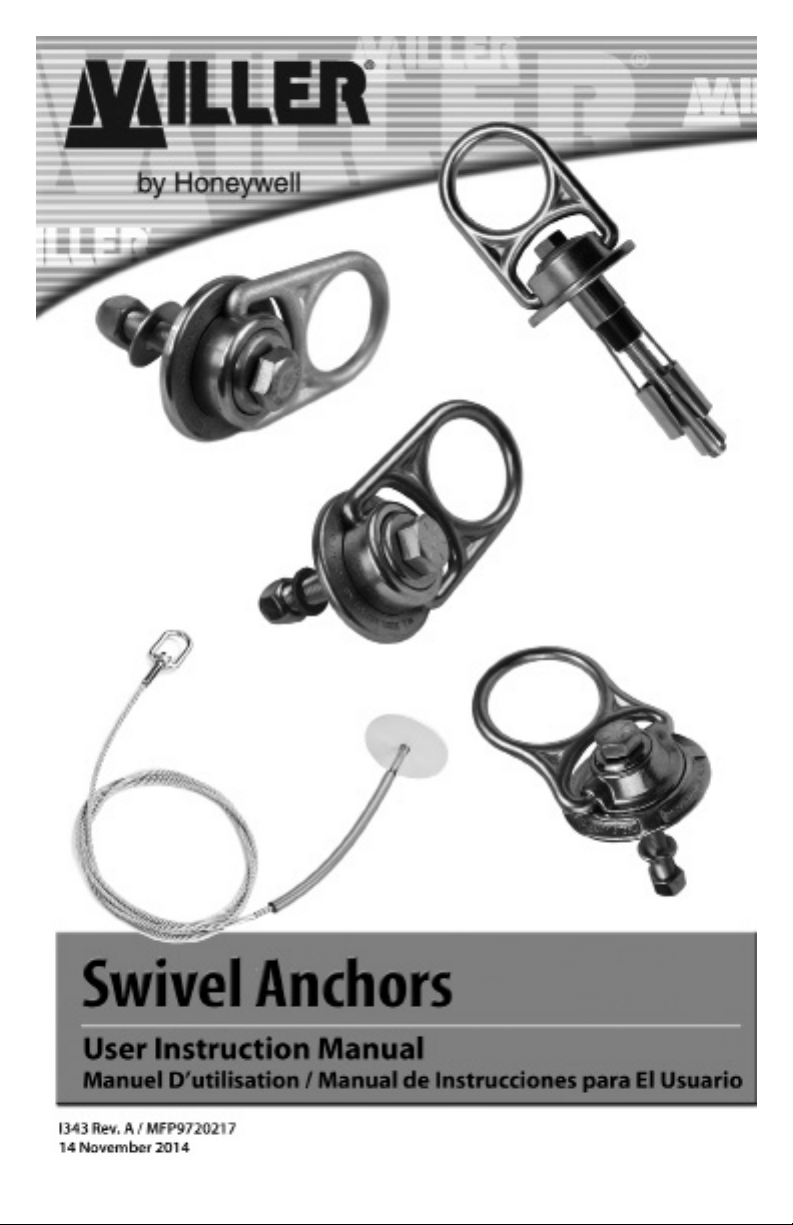
Installation:
1. The drop through anchor-5k drop through anchor can only be used on a horizontal
surface that is above the users location.
2. Locate or create a through hole in concrete, steel or metal grating capable of
withstanding a 5,000-lbf. Static load or meeting OSHA 1926.502 requirements for a
safety factor of two. (Reference gure 1-A below for dimentional requirements.)
3. Place cable through the hole from top side. The label on plate should be facing up.
Plate must rest at and ush on the mounting surface.
1-3/4” to 2”Ø
Hole size
(4.1cm to 4.4cm)
(A)
e
g
d
e
ny
a
m
ro
f
in
m
(B)
min
Fig. 1-A
HOLE REQUIRMENT CHART
Material: (A)” Minimum distance from edge/corner (B)” thickness
Concrete
Steel
12” in. (30.5 cm)
4” in. (10 cm)
6
4” in. (10 cm)
1/4” in. (.635 cm)
Page 7
User Instructions - English
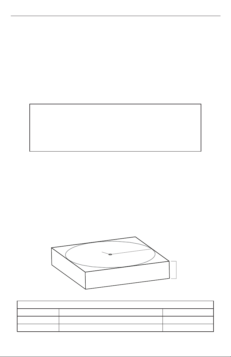
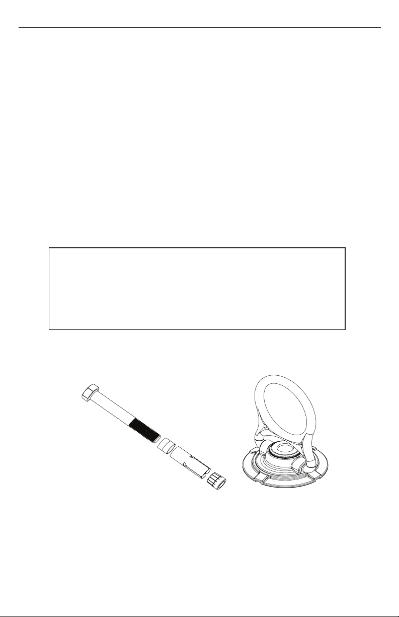
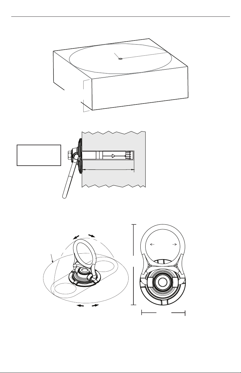
5.0 Zinc-Plated Swivel Anchor
5,000 lbf./22kN
Model Numbers RACSWY050N (swivel only), RACSWY050S (swivel anchor with steel mounting hardware), and RACSWY050C (swivel anchor with concrete mounting hardware), RACSWY2SBA (Steel mounting hardware only) and RACSWY2CSA (Concrete mounting hardware
only).
Warnings and Limitations
• Use only with Honeywell-approved personal fall arrest or restraint systems. The
anchorage must have the strength capable of supporting a static load, applied in
the directions permitted by the system, of at least 5,000-lbf (22kN) in the absence of
certication.
• The anchorage connector may be pulled in any direction shown in the LOADING
CONDITIONS DIAGRAM (pg. 9).
Tensile Strength (UTS): 5,000-lbf (22kN)
Working Load (WLL): 1,000 lbs (454kg)
Maximum Capacity: One worker, 310 lbs (140 kg)
Weight: 1.2 lbs (544.31g)
Regulatory Compliance
ANSI Z359.1-2007, ANSI Z359.7-2011, OSHA 1910.66 , 1926.502
CONCRETE MOUNTING RACSWY050C:
+
- Use a proper drill & bit for concrete. (SDS drill bit)
- Drill a 5/8” (16mm) hole no less than 4” (102mm) deep an 8” (203mm) away from
any edge.
- Hole must be straight & perpendicular to surface.
- Hole must be free of debris
- Concrete strength must be at least 3000psi (20.7MPa) and no less than 7”
(178mm) thick.
7
Page 8
User Instructions - English
Torque:
60ft-lbs
7”
(178mm)
min
drill 5/8” (16mm)Ø
4” min (102mm)
8” (203mm)
min from any edge
8.0”ø
(203.2mm)
180˚
360˚
8
5.5”
(139.7mm)
2.25”ø
(57.15mm)
3.0”
(76.2mm)
Page 9
User Instructions - English
LOADING CONDITIONS DIAGRAM
LOAD
ACCEPTABLE ACCEPTABLE
LOAD
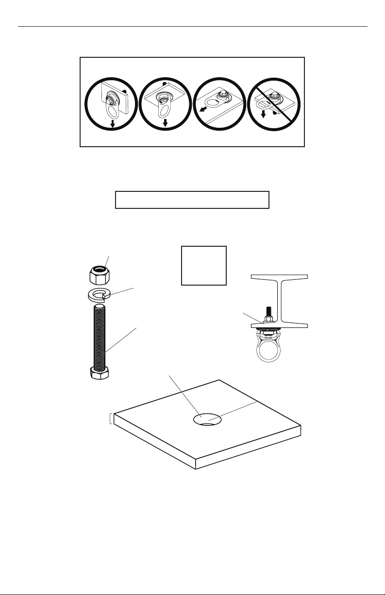
STEEL MOUNTING
1/2”-13 Lock Nut
1/2” Lock
Washer
1/2”-13 x 4”
Hex Bolt *
drill 1/2” (12.7mm)Ø
LOAD
Torque :
45 ft-lbs
(61 Nm)
LOAD
IMPROPERACCEPTABLE
Use
tapered
washer
1/4”
(6mm)
min
3”(76mm)
min from any edge
9
Page 10

User Instructions - English
6.0 Stainless Steel Swivel Anchors
5,000 lbf/22kN
Model Numbers RACSWS100N-316 (swivel only), RACSWS100S-316 (Swivel anchor with
stainless steel mounting hardware), and RACSWS100C-316 (Swivel anchor with concrete
mounting hardware), RACSWS1SBA-316 (Stainless steel mounting hardware only), RACSWS1DNC-316 (Concrete mounting hardware only), RACDNC-TOOL (Concrete bolt assembly tool)
and RACSWP100N-316 (Weld Kit).
Warnings and Limitations
• Use only with Honeywell-approved personal fall arrest or restraint systems. The anchorage
must have the strength capable of supporting a static load, applied in the directions
permitted by the system, of at least 5,000-lbf (22kN) in the absence of certication.
• The anchorage connector may be pulled in any direction shown in the LOADING
CONDITIONS DIAGRAM (below)
180°
8.0”ø
(203.2mm)
5.5”
(139.7mm)
2.25”ø
(57.15mm)
360°
3.0”
(76.2mm)
Tensile Strength (UTS): 10,000-lbf (44kN)
Working Load (WLL): 1,000 lbs (454kg)
Maximum Capacity: One worker, 310 lbs (140 kg)
Weight: 1.2 lbs (544.3g)
Regulatory Compliance
ANSI Z359.1-2007, ANSI Z359.7-2011, OSHA 1910.66 , 1926.502
LOADING CONDITIONS DIAGRAM
LOAD
LOAD
ACCEPTABLE ACCEPTABLE IMPROPER
LOAD
LOAD
ACCEPTABLE
10
1.0”
(25.4mm)
Page 11

User Instructions - English
CONCRETE MOUNTING
- Use a proper drill & bit for concrete. (SDS drill bit)
- Drill a 7/8” (22mm) hole no less than 3” to 3-1/2“ (76mm-89mm) deep 9” (229mm)
away from any edge.
- Hole must be straight & perpendicular to surface.
- Hole must be free of debris
- Concrete strength must be at least 3000psi (20.7MPa) and no less than 7” (178mm)
thick.
-Drop expansion sleeve into hole.
-Use the Setting Tool by placing it in the hole resting on the expansion sleeve. Tap
tool until the blue inner sleeve is at the bottom of the expansion sleeve.
-Now place swivel over the hole and install the bolt provided.
Embedment Depth
3” min 3-1/2” max
(76mm-89mm)
TA
P
drill 3/4” (19mm)Ø
!!!
Setting Tool
(DNC-TOOL)
9” (229mm)
min from any edge
7"
(178mm)
min.
Torque Range:
30-40 ft-lbs
(22-30Nm)
Expansion
Sleeve
11
Page 12

5/8”-11
Lock Nut
User Instructions - English
STEEL MOUNTING
Torque Range:
75 ft-lbs.
(100Nm)
5/8” Lock
Washer
drill 5/8” (16mm)Ø
5/8”-11x4”
Hex Bolt *
* For steel applications a grade-5, 8 (or equivalent) bolt no shorter than 4” (100mm)
with a locking nut and washer must be used. Swivel anchor must be ush with steel
surface. A 16mm bolt may be used in place of a 5/8”-11 for metric applications.
1/4"
(6mm)
min.
* Use tapered washer with Ibeams that have tapered anges
3”(76mm)
min from any
edge
WELD-ON MOUNTING
316 Stainless Steel 5/8”-
11 x 1-3/4” Bolt
Torque:
85-ft lbs
(115Nm)
Puck
* Weld
* Welding procedure must be approved by a Engineer or other
qualied person to be compatible with any and all structural &
operational characteristics of the selected installation location.
12
Page 13

User Instructions - English
KIT CONTENTS
+
CONCRETE METALACCESSORIES
+
PART NUMBER
RACSWS1SBA-316
(Steel Mounting Hardware Kit)
RACSWS100S-316
(Swivel with Steel Mounting kit)
RACSWS1DNC-316
(Concrete Hardware Kit)
RACSWS100C-316
(Swivel with Concrete Mounting Kit)
+
RACSWP100N-316KIT
(Weld-on Mounting Kit)
RACDNC-TOOL
(Concrete Anchor Tool)
13
Page 14

User Instructions - English
7.0 Zinc Plated Swivel Anchors
10,000 lbf/44kN
Model Numbers RACSWY100N (Swivel only), RACSWY100S (Swivel anchor with steel mounting hardware), and RACSWY100C (Swivel anchor with concrete mounting hardware), RAC-
SWY1SBA (Steel mounting hardware only), RACSWY1CSA (Concrete mounting hardware),
RACSWP100N-KIT (Weld kit) and RACSWX100N (Steel back plate).
Warnings and Limitations
• Use only with Honeywell-approved personal fall arrest or restraint systems. The anchorage
must have the strength capable of supporting a static load, applied in the directions
permitted by the system, of at least 10,000-lbf (22kN) in the absence of certication.
• The anchorage connector may be pulled in any direction shown in the LOADING
CONDITIONS DIAGRAM (Pg. 15)
180°
8.0”ø
(203.2mm)
5.5”
(139.7mm)
2.25”ø
(57.15mm)
360°
(76.2mm)
Tensile Strength (UTS): 10,000-lbf (44kN)
Working Load (WLL): 2,000 lbs (907kg)
Maximum Capacity: One worker, 310 lbs (140 kg)
Weight: 1.2 lbs (544.3g)
Regulatory Compliance
ANSI Z359.1-2007, ANSI Z359.7-2011, OSHA 1910.66,
14
3.0”
1926.502
1.0”
(25.4mm)
Page 15

User Instructions - English
LOADING CONDITIONS DIAGRAM
5/8”-11
Lock Nut
LOAD
LOAD
ACCEPTABLE ACCEPTABLE IMPROPER
LOAD
LOAD
ACCEPTABLE
STEEL MOUNTING
Torque Range:
5/8” Lock
Washer
5/8”-11x4”
Hex Bolt *
75-90 ft-lbs
(100-120 Nm)
drill 5/8” (16mm)Ø
1/4”
(6mm)
min.
* Use tapered washer with I-beams
that have tapered anges
3”(76mm)
min from any edge
* For steel applications a grade-5, 8 (or equivalent) bolt no shorter
than 4” (100mm) with a locking nut and washer must be used.
Swivel anchor must be ush with steel surface. A 16mm bolt may be
used in place of a 5/8”-11 for metric applications.
15
Page 16

User Instructions - English
CONCRETE MOUNTING
- Use a proper drill & bit for concrete. (SDS drill bit)
- Drill a 3/4” (19mm) hole no less than 5” (127mm) deep 9” (229mm) away from any edge.
- Hole must be straight & perpendicular to surface.
- Hole must be free of debris
- Concrete strength must be at least 3000psi (20.7MPa) and no less than 7” (178mm) thick.
drill 3/4” (19mm)Ø
9” (229mm)
min from any edge
Torque:
90ft-lbs
(120Nm)
WELD ON MOUNTING
Grade - 5 or 8 bolt
5/8”-11 x 1-3/4”
Torque:
125-ft-lbs
(169Nm)
15/16” socket required
7"
(178mm)
min.
4” min (102mm)
Embedment Depth
Puck
* Weld
3/8"min.
(9.5mm)
* Welding procedure must be approved by an Engineer or other qualied
person to be compatible with any and all structural & operational characteristics of the selected installation location.
16
Page 17

User Instructions - English
BACK PLATE MOUNTING
Back Plate to be used with 5/8” (16mm)
bolts or all thread. Drill hole perpendicular into surface so bolt can pass freely
through the substrate. Nut must be fully
threaded on the bolt to insure maximum
strength ratings and integrity of anchor.
Torque Range:
to be determined
by an Engineer or
qualied person.
* Bolt or All-thread and nut not included with Back Plate.
17
Page 18

User Instructions - English
KIT CONTENTS
+
CONCRETE METALACCESSORIES
+
PART NUMBER
RACSWY1SBA
(Steel Mounting Hardware Kit)
RACSWY100S
(Swivel with Steel Mounting kit)
RACSWY1CSA
(Concrete Hardware Kit)
RACSWY100C
(Swivel with Concrete Mounting Kit)
+
RACSWP100N-KIT
(Weld-on Mounting Kit)
RACSWX100N
(Backing Plate Only)
18
Page 19

User Instructions - English
8.0 Hybrid Concrete Anchor
Model Number RACSWH100Y
Warnings and Limitations
• Use only with Honeywell-approved personal fall arrest or restraint systems. The anchorage
must have the strength capable of supporting a static load, applied in the directions
permitted by the system, of at least 10,000-lbf (22kN) in the absence of certication.
• The anchorage connector may be pulled in any direction shown in the LOADING
CONDITIONS DIAGRAM (Pg. 20)
6-1/4”
(15.88cm)
2.25”ø
(57.15mm)
5.5”
(139.7mm)
Compression
Bushing
Sleeve
3.0”
(76.2mm)
8.0”ø
(203.2mm)
1.0”
(25.4mm)
180˚
360˚
19
Retaining
Bushing
Cable
Bolt
Spoon
Cone
Page 20

User Instructions - English
LOADING CONDITIONS DIAGRAM
LOAD
LOAD
ACCEPTABLE ACCEPTABLE
LOAD
LOAD
IMPROPERACCEPTABLE
Tensile Strength (UTS): 10,000-lbf (44kN)
Working Load (WLL): 1.000 lbs (454kg)
Maximum Capacity: One worker, 310 lbs (140kg)
Weight: 2.0-lbs (949g)
Regulatory Compliance: ANSI Z359.1-2007, ANSI Z359.7-
2011, OSHA 1910.66 , 1926.502
DRILLING :
1. Use a hammer drill (SDS), drill a 1” (25mm) diameter hole at least 5”
(127mm) deep. The drilled hole must be straight and perpendicular to
the surface. Make sure the hole is of uniform diameter and free of peaks and
valleys on the inner wall. See diagram below.
2. Blow hole clean with compressed air.
3. Refer to the diagram below for hole location and requirements.
4. Always inspect the hole carefully when reusing a previously drilled hole.
Hole to Edge:
Drill 1ӯ
(2.54cm)
10”
(25.4cm)
min from any edge
Section View:
1”min
(2.54cm)
20
6”min
(15.24cm)
5” min
depth
(12.7cm)
Page 21

User Instructions - English
Check for kinked
or frayed cables.
Look for signs
of wear on
spoons.
INSPECT BEFORE USE
Check for deformation
of cone.
INSTALLATION:
1. Before installing make sure the
cone is below the spoons. Insert the
anchor into hole so the base plate rest
at on the concrete surface.
Drop In
Swivel should
move freely.
2. Pull up on the bolt while holding
swivel ush with the concrete. Tighten
the bolt by turning it clockwise by
hand until bolt is fastened ush to
swivel.
Step 1.
3. Use a torque wrench to set the pretension on the bolt for the loading situation
required for the application.
LOAD: BOLT TORQUE:
10,000-lbf
(44 kN)
5,000-lbf
(22 kN)
85-ft-lbs
(9.60 Nm)
30-ft-lbs
(3.38 Nm)
Pull Up
Bolt &
Step 2.
Twist
Clockwise
Step 3.
21
Page 22

User Instructions - English
REMOVAL:
1. Loosen bolt so that at least 3/4”
(1.9cm) of threads are exposed.
Unscrew
min of
3/4”
(1.9cm)
2. Use a hammer to tap down bolt and
disengage cone from the spoons.
Step 1.
TAP!!!
Step 2.
3. Pull the anchor from the hole.
Step 3.
22
Page 23

User Instructions - English
4.0 Inspection and Maintenance
Inspection
Miller Anchorage Connectors are designed for today’s rugged work environments. To maintain
their service life and high performance, all components should be inspected frequently.
Anchorage connectors must be visually inspected by the user before each use and
inspected by a Competent Person on a regular basis.
Inspect product for any of the following: bent, cracked, distorted, worn, malfunctioning or
damaged parts; loose fasteners or missing parts/components; deterioration; deformation;
corrosion; signs that indicate the product has been subjected to a fall arrest; or any other
indications of damage/problems that may affect the integrity and operation of the product. If in
doubt, contact the manufacturer.
Devices that do not pass inspection
or have been subjected to fall arresting forces
must be removed from service.
Cleaning and Storage
Basic care of all Miller Fall Protection equipment will prolong the life of the unit and will contribute toward the performance of its vital safety function. Periodically clean the device to remove
any dirt, paint, corrosives, contaminants, or other materials that may have accumulated. When
not in use, store in a clean, dry area, free of exposure to furmes or corrosive elements.
Servicing
Servicing of Miller fall protection equipment must only be carried out by Honeywell Safety Products or persons or entities authorized in writing by Honeywell. A record log of all servicing and
inspection dates for this device must be maintained. Only original Honeywell replacement parts
are approved for use in this device. Non-repairable devices that do not pass inspection must
be disposed of in a manner to prevent inadvertent further use. Contact Honeywell Technical
Service at 800.873.5242 if you have any questions.
23
Page 24

Étiquettes de Produit
Etiquetas del Producto
5K Swivel AnchorRAC-
SWY050N
User Instructions - English
Product Labels
LABEL LOCATIONS
5K Swivel Anchor
Model: RACSWY050N
5K Stainless Steel
Swivel Anchor
RACSWY100N
WARNING: All persons using this equipment must read,
understand and follow all instructions. Failure to do so may
result in serious injury or death.
COMPLIANCE: OSHA 1910.66 & 1926.502 ANSI Z359.1-07
CE 0321 / EN 795:1996 (US PAT # 8,424,638)
Z359.7-11
(INSPECT BEFORE USE)
24
5k S.S. Swivel Anchor
Zinc Plated Steel
Max Capacity:
(1) person 310-lbs
Working Load 2,000-lbs
Model: RACSWY100N
Page 25

User Instructions - English
5K Drop-Through Swivel Anchor
RACDTA-5K/
Polyurethane Sleeve
4"0 3/16" Plate
(Length Specied by Customer)
Aircraft Cable
25
Page 26

User Instructions - English
10K Zinc-Plated Steel
Swivel Anchor
WARNING: All persons using this equipment must read,
understand and follow all instructions. Failure to do so may
result in serious injury or death.
COMPLIANCE: OSHA 1910.66 & 1926.502 ANSI Z359.1-07
(US PAT # 8,424,638)
Z359.7-11
(INSPECT BEFORE USE)
10K Swivel Hybrid Anchor
10k Swivel Anchor
Zinc Plated Steel
Max Capacity:
(1) person 310-lbs
Working Load 2,000-lbs
Model: RACSWY100N
WARNING: All persons using this equipment must read,
understand and follow all instructions. Failure to do so may result in
serious injury or death. (INSPECT BEFORE USE)
COMPLIANCE: OSHA 1910.66 & 1926.502 ANSI Z359.1-07 Z359.7-11
26
10k Hybrid Anchor
Zinc Plated Steel
Max Capacity:
(1) person 310-lbs
Model: RACSWH100Y
Page 27

Inspection and Maintenance Log
Registre D'inspection et D'entretien
Registro de Inspección y Mantenimiento
DATE OF MANUFACTURE:_________________________________________________
DATE DE FABRICATION / FECHA DE FABRICACIÓN
MODEL NUMBER:________________________________________________________
NUMÉRO DE MODÈLE / NÚM. DE MODELO
DATE PURCHASED:______________________________________________________
DATE D’ACHAT / FECHA DE COMPRA
INSPECTION DATE
DATE D’INSPECTION
FECHA DE INSPECCIÓN
Approved by:
Approuvé par:
Aprobado por:
Approved by:
Approuvé par:
Aprobado por:
Approved by:
Approuvé par:
Aprobado por:
Approved by:
Approuvé par:
Aprobado por:
Approved by:
Approuvé par:
Aprobado por:
Approved by:
Approuvé par:
Aprobado por:
INSPECTION
ITEMS NOTED
POINTS NOTÉS
LORS DE L’INSPECTION
PUNTOS DE INSPECCIÓN
RELEVANTES
CORRECTIVE
ACTION
ACTION CORRECTIVE
MEDIDA CORRECTIVA
MAINTENANCE
PERFORMED
ENTRETIEN EFFECTUÉ
MANTENIMIENTO
REALIZADO
Approved by:
Approuvé par:
Aprobado por:
Approved by:
Approuvé par:
Aprobado por:
Approved by:
Approuvé par:
Aprobado por:
Approved by:
Approuvé par:
Aprobado por:
27
Page 28

MILLER® FALL PROTECTION PRODUCTS
TOTAL SATISFACTION ASSURANCE
At Honeywell Safety Products and its predecessors, we have been providing quality Miller brand
Our products endure rigorous tests to ensure that the fall protection equipment you trust is manufactured
to the highest standards. Miller fall protection products are tested to withstand normal wear and tear,
Our Limited Lifetime Warranty does not apply to normal wear and tear or abusive treatment of the product.
If a replacement is necessary and your product is no longer available, a comparable product will be substituted.
fall protection equipment to millions of workers worldwide since 1945.
LIMITED LIFETIME WARRANTY
BACKED BY OVER 65 YEARS IN THE FALL PROTECTION BUSINESS
We sincerely believe that our fall protection equipment is the best in the world.
but are not indestructible and can be damaged by misuse.
In the unlikely event that you should discover defects in either workmanship or materials,
under our Limited Lifetime Warranty, we will repair or replace the product at our expense.
Should a product issue surface, contact us at 800.873.5242.
Manufacturing specications are subject to change without notice.
PRODUITS MILLER® FALL PROTECTION
ASSURANCE DE SATISFACTION TOTALE
Honeywell Safety Products et ses prédécesseurs offrent les équipements antichute de marque Miller
ASSURÉE GRÂCE À PLUS DE 65 ANS PASSÉS DANS LE DOMAINE DE LA PROTECTION CONTRE LES CHUTES
Nous croyons sincèrement que notre équipement de protection contre les chutes est le meilleur au monde. Nos
Les produits de protection contre les chutes Miller sont soumis à des essais pour vérier qu’ils résistent à une usure
normale; ils ne sont cependant pas indestructibles et peuvent s’endommager en cas de mauvaise utilisation. Notre
de qualité à des millions de travailleurs dans le monde entier depuis 1945.
GARANTIE LIMITÉE À VIE
produits sont soumis à des tests rigoureux, an d’assurer que les équipements de protection contre
les chutes dans lesquels vous avez conance sont fabriqués selon les normes les plus exigeantes.
garantie limitée à vie ne s’applique pas à l’usure normale ou à un usage abusif du produit.
Dans le cas peu probable où vous découvririez des défauts, soit de fabrication, soit de matériau,
dans le cadre de notre garantie à vie, nous réparerons ou remplacerons le produit à nos frais.
En cas de remplacement, si votre produit n’est plus offert, vous recevrez un produit comparable.
En cas de problème sur un produit, nous contacter au 800-873-5242.
Les caractéristiques de fabrication peuvent être modiées sans préavis.
PRODUCTOS ANTICAÍDAS MILLER
®
GARANTÍA DE SATISFACCIÓN TOTAL
En Honeywell Safety Products y sus predecesores, hemos estado brindando la calidad de la marca Miller en
equipos de protección de caída a millones de trabajadores alrededor del mundo desde 1945.
NOS RESPALDAN MÁS DE 65 AÑOS EN LA FABRICACIÓN DE EQUIPO ANTICAÍDAS
Sinceramente creemos que su equipo de protección contra caídas es el mejor del mundo. Nuestros productos resisten
rigurosas pruebas para garantizar que el equipo de protección contra caídas en el que usted confía está fabricado de
conformidad con las normas más elevadas. Los productos anticaídas Miller son sometidos a pruebas para que resistan el
desgaste normal, pero no son indestructibles y su incorrecta utilización puede dañarlos.
Nuestra Garantía limitada de por vida no se aplica al desgaste normal ni al maltrato del producto.
En el poco probable caso de que usted descubriera defectos de mano de obra o materiales, por nuestra Garantía lim-
itada de por vida, repararemos o sustituiremos el producto por cuenta nuestra. Si un reemplazo es necesario y nuestro
producto ya no está disponible, se lo sustituiremos por otro comparable.
En caso de que surja un problema con el producto, contáctenos al 800.873.5242.
Las especicaciones de fabricación están sujetas a modicaciones sin previo aviso.
GARANTÍA LIMITADA DE POR VIDA
28
Page 29

User Instructions - English
29
Page 30

Toll Free: 800.873.5242
Fax: 800.892.4078
Download this manual at: www.millerfallprotection.com
Téléchargez ce manuel à l’adresse: www.millerfallprotection.com
Puede bajar por Internet este manual en: www.millerfallprotection.com
Honeywell Safety Products
P.O. Box 271, 1345 15th Street
Franklin, PA 16323 USA
 Loading...