

Page 1

OWNER’S MANUAL
Power Source Interface
1. Safety Symbol Definitions
Means Warning! Watch Out! There are possible hazards
with this procedure! The possible hazards are shown in
the adjoining symbols.
Symbole graphique d’avertissement! Attention! Cette procédure comporte des risques possibles! Les dangers
éventuels sont représentés par les symboles graphiques
joints.
Beware of electric shock from wiring.
Attention! Risque d’électrocution due au contact avec des
fils.
2. Specifications
Specification Description
OM‐240 829‐B 2009-06
Have only trained and qualified persons install, operate,
or service this unit. Call your distributor if you do not understand the directions. For WELDING SAFETY and
EMF information, read wire feeder and welding power
source manuals.
L’installation, l’exploitation et l’entretien de cet appareil
doivent être confiés uniquement à des personnes
qualifiées et convenablement formées. S’adresser à un
distributeur si l’on ne comprend pas les directives. Pour
des renseignements ayant trait à la SÉCURITÉ lors du
soudage et aux champs électromagnétiques, consulter
les manuels traitant les dévidoirs et les sources de
courant pour le soudage.
Wear safety glasses with side shields.
Porter des lunettes de sécurité avec protections latérales.
Type Of Input Power Single-Phase 115 Volts AC, 0.025 amperes (25 mA), 50/60 Hertz
Welding Power Source Type Constant Current (CC), Constant Voltage (CV), AC Or DC
Overall Dimensions Length: 16.5 in. (419 mm); Width: 7.5 in. (191 mm); Height: 8.9 in. (226 mm)
Weight Weld Control — Net: 26.5 lb (12.02 kg)
Weld Voltage And Amperage
Capacity (AC Or DC)
0 To 500 Volts
0 To 1500 Amperes
3. Description/Dimensions
The power source interface is designed to allow the use of a MILLER
7.5 in.
(191 mm)
HDC-1500A when using an engine
driven power source.
S/N: KJ
043009-011
ARCCOOL V3
8.9 in.
(226 mm)
U
1
=
I
=
1
LR5071
5.5
V
A
1
IP 23
Hz50/60
NRTL/C
MILLER ELECTRIC MFG. CO., APPLETON, WI USA
16.5 in.
(419 mm)
Ref. 300 537
Page 2
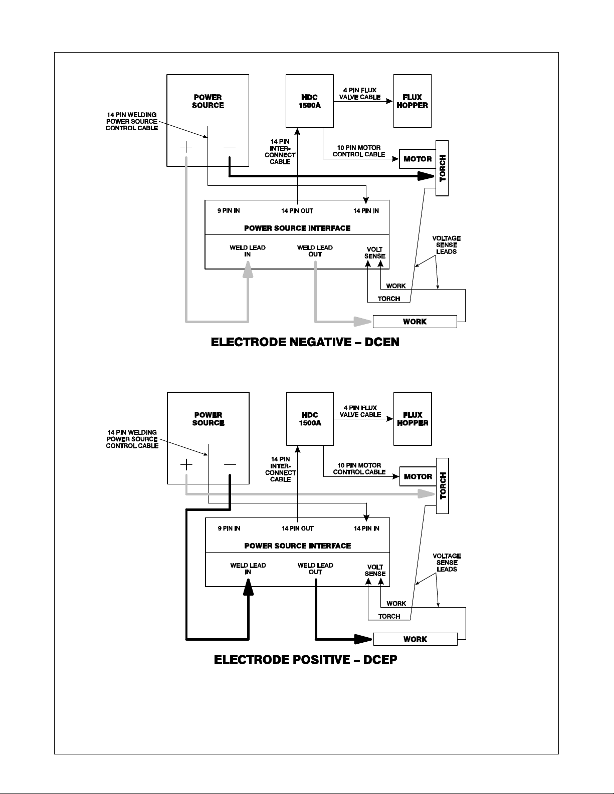
4. DCEN/DCEP Connection Diagram
Select and prepare correct size and length
of weld cables according to the welding
power source Owners manual. Lift up cover to access connections.
Route and connect a weld cable from selected weld output terminal on welding power
OM-240 829 Page 2
source to torch and other output stud to
power source on the interface. Connect the
work connections on the interface to the
work piece.
Route volt sense leads as follows:
One from torch to torch on interface, and
244 861-A
one from work to the opposite end of work
piece; opposite the work connection.
Connect 14-pin cable from power source to
14-pin “In” on interface. Connect 14-pin
“Out” to 14-pin on HDC1500A.
Close cover and replace screws.
Page 3

SECTION 5 − CIRCUIT DIAGRAM
240 831-B
OM-240 829 Page 3
Page 4

SECTION 6 − PARTS LIST
. Hardware is common and
not available unless listed.
13
12
11
9
10
8
5
4
3
2
1
7
6
17
14
15
16
OM-240 829 Page 4
19
18
20
21
22
Ref. 300 537-A
Figure 6-1. Interface Components
Page 5

Item
No.
Dia.
Mkgs.
Part
No.
Description
Figure 6-1. Interface Components
1 201 606 Hinge, Continuous Stl Stnls .042 X 2.00 X 15.00 1. . . . . . . . . . . . . . . . . . . . . . . . . . . . . . . . . . . . . . .
2 190 960 Terminal Assy, Power Output 2. . . . . . . . . . . . . . . . . . . . . . . . . . . . . . . . . . . . . . . . . . . . . . . . . . . . . . . .
3 240 401 Bracket, Mounting Lem 1. . . . . . . . . . . . . . . . . . . . . . . . . . . . . . . . . . . . . . . . . . . . . . . . . . . . . . . . . . . . .
4 208 219 Transducer, Current 1000A Module Supply V 15V 1. . . . . . . . . . . . . . . . . . . . . . . . . . . . . . . . . . . . . .
5 242 797 Label, Rating Card 1. . . . . . . . . . . . . . . . . . . . . . . . . . . . . . . . . . . . . . . . . . . . . . . . . . . . . . . . . . . . . . . . .
6 240 824 Plug Assy, 14 Pin−In PSI 1. . . . . . . . . . . . . . . . . . . . . . . . . . . . . . . . . . . . . . . . . . . . . . . . . . . . . . . . . . .
7 240 825 Plug Assy, 14 Pin−Out PSI 1. . . . . . . . . . . . . . . . . . . . . . . . . . . . . . . . . . . . . . . . . . . . . . . . . . . . . . . . . .
8 240 823 Plug Assy, 9 Pin PSI 1. . . . . . . . . . . . . . . . . . . . . . . . . . . . . . . . . . . . . . . . . . . . . . . . . . . . . . . . . . . . . . .
9 238 529 Circuit Card Assy, Power Source Interface 1. . . . . . . . . . . . . . . . . . . . . . . . . . . . . . . . . . . . . . . . . . . .
10 240 396 Bracket, Mtg PC Board 1. . . . . . . . . . . . . . . . . . . . . . . . . . . . . . . . . . . . . . . . . . . . . . . . . . . . . . . . . . . . .
11 240 831 Ckt, Power Source Interface 1. . . . . . . . . . . . . . . . . . . . . . . . . . . . . . . . . . . . . . . . . . . . . . . . . . . . . . . .
12 240 393 Cover, Enclosure 1. . . . . . . . . . . . . . . . . . . . . . . . . . . . . . . . . . . . . . . . . . . . . . . . . . . . . . . . . . . . . . . . . .
13 134 327 Label, Warning General Precautionary Static&Wire Fe 1. . . . . . . . . . . . . . . . . . . . . . . . . . . . . . . . . .
14 240 391 Bracket, Mtg Upper 1. . . . . . . . . . . . . . . . . . . . . . . . . . . . . . . . . . . . . . . . . . . . . . . . . . . . . . . . . . . . . . . .
15 240 390 Bracket, Mtg Lower 1. . . . . . . . . . . . . . . . . . . . . . . . . . . . . . . . . . . . . . . . . . . . . . . . . . . . . . . . . . . . . . . .
16 240 384 Box Assy, Enclosure 1. . . . . . . . . . . . . . . . . . . . . . . . . . . . . . . . . . . . . . . . . . . . . . . . . . . . . . . . . . . . . . .
17 202 028 Bus Bar, Lem PSI 1. . . . . . . . . . . . . . . . . . . . . . . . . . . . . . . . . . . . . . . . . . . . . . . . . . . . . . . . . . . . . . . . .
18 240 386 Panel, Mtg Terminal 1. . . . . . . . . . . . . . . . . . . . . . . . . . . . . . . . . . . . . . . . . . . . . . . . . . . . . . . . . . . . . . . .
19 241 411 Nameplate, Power Source Interface 1. . . . . . . . . . . . . . . . . . . . . . . . . . . . . . . . . . . . . . . . . . . . . . . . . .
20 202 870 Block, Term 30 Amp 2 Pole Screw Term 1. . . . . . . . . . . . . . . . . . . . . . . . . . . . . . . . . . . . . . . . . . . . . .
21 010 828 Handle 2. . . . . . . . . . . . . . . . . . . . . . . . . . . . . . . . . . . . . . . . . . . . . . . . . . . . . . . . . . . . . . . . . . . . . . . . . . .
22 240 387 Door, Cover Terminal 1. . . . . . . . . . . . . . . . . . . . . . . . . . . . . . . . . . . . . . . . . . . . . . . . . . . . . . . . . . . . . .
Quantity
+When ordering a component originally displaying a precautionary label, the label should also be ordered.
To maintain the factory original performance of your equipment, use only Manufacturer’s Suggested
Replacement Parts. Model and serial number required when ordering parts from your local distributor.
OM-240 829 Page 5
 Loading...