

Page 1
IMPORTANT
contents
the
of
safety
installing,
ment.
only
operation
trained
unit.
understand
This
by
persons
persons
Contact
of
Read
manual,
this
material
throughout
operating,
unit
and
trained
welding
to
install,
distributor
your
these
instructions.
understand
and
with
or
maintaining
instructions
these
and
experienced
equipment.
operate,
special
the
manual,
Do
or
if
you
the
emphasis
this
for
are
in
the
allow
not
maintain
do
not
entire
on
before
equip
use
safe
un
this
fully
June
Effective
1989
With
Serial
AUTO
sPW1
FORM:
No.
MODEL
ARC
JK585798
MW
113
4150
336B
~Fftr~
,
I
44J
I
~F
OWN
MANUAL
A.rl__
I
II%W~J.
718
ELECTRIC
BOUNDS
S.
APPLETON,
ADDITIONAL
NWSA
PRINTED
WI
COPY
CODE
IN
MILLER
ERS
MFG.
Box
P.O.
ST.
54912
USA
PRICE
$145
NO.
4579
U.S.A.
CO.
1079
Page 2
ONE
YEAR
LIMITED
WARRANTY
COVERAGE
who
purchases
familyorhouseholdpurposes(Consumer)thatthisWelderwill
free
be
one
year
the
original
authorize
other
any
of
the
warranty
ityrelatedtothoWelder,exceptonwarrantyclaimsmadeduring
the
warranty
THIS
EXPRESS
PROHIBITED
ALL
IMPLIED
LIMITED
TABILITYAND
LIMITED
Some
warranty
This
warranty
have
other
Exceptasspecified
components
such
as
in
come
nozzle
workmanship
Miller
Equipment
the
following
the
original
Arc
1.
2.
Original
(labor
All
3.
4.
Replacement
WHAT
Welder
any
warranty
warranty
sonal,
trial
users
Miller
this
defectsinmaterial
from
from
the
purchaser
party,
any
warranty
period,
period,
WARRANTY
WARRANTY;
BY
WARRANTIES,
TO
THE
FITNESS
TO
THE
statesdonot
so
lasts,
gives
which
rights
having
welder
spot
contact
in
IS
NOT
with
material.
or
be
required
the
periods
user:
power
main
1
year
guns,
COVERED
where
event
power
or
insulators
shall
welders,
welding
subjected
repair
by
extends
only
household
or
family
are
given
Electric
Auto
Arc
date
of
purchase.
of
this
including
behalfofMiller
on
Miller
IS
OFFERED
AND,
APPLICABLE
IMPLIED
FORAPARTICULAR
DURATION
allow
the
above
specific
you
vary
below,
normal
useful
tips,
relay
the
welding
failure
to
honorwarranty
of
failure
from
the
sources,
rectifiers
only)
feeder/guns
repair
parts,
to
misuse,
except
anyone
to
those
purposes.
different
a
Co.
Mfg.
Welder
andworkmanship
Welder.
authorized
its
Electric
WARRANTIES
OF
limitationsonhow
limitation
from
Millers
and
does
date
This
purchasing
warrants
(Welder)
This
warranty
Miller
Electric.
shall
havenofurther
LIEUOFANY
IN
EXCEPT
THE
LAW,
INCLUDING
THIS
WARRANTY.
may
rights,
legal
to
state
warranty
life
of less
contactor
wire
including
not
resulting
of
delivery
and
components
and
torches
exclusive
warranty
neglect,
Miller
Electric.
Commercial
result
claims
fromadefect
warranty.
to
the
buyer
for
personal,
fora
period
covers
Electric
does
distributors,
Upon
TO
DURATION
OF
expiration
THE
EXTENT
BUT
MERCI-IAN
to
OTHER
PURPOSE,
an
implied
long
not
and
state.
does
than
points,
of
of
labor
does
accident,
the
apply
you
may
not
apply
one
(1)
parts
nozzles
from
defect
warranted
on
Equipment
...
3
90
60
not
extend
Further,
Welder
for
and
to
within
1
or
indus
of
only
not
offer
liabil-
OF
NOT
IS
you.
also
to
year,
that
and
in
to
year
years
days
days
to
in-
this
per
REMEDY
defective
place
purchase
use),
placement
vided
dure
Welder
the
charges
States
Hawaii
THE
WELDER,
LAW,
WARRANTY:
UNDER
NO
TAL
OF,
BASED
ELECTRICS
THEORY
Some
quential
not
apply
PROCEDURE
ANCE
As
chaser
approved
defect.
period,
dress:
Miller
1635
P.O.
Appleton,
All
Electric
FOR
DEFECTIVE
Miller
Welder,
defective
the
(less
price
reimburse
or
atan
that
for
so
purchaser
(transportation
will
ARE
EVENT
OR
OR
soon
of
The
return
transportation
approved
the
purchaser
obtaining
repaired
of
to
prepaid
be
paid
PURCHASERS
TO
THE
LIMITED
AND,
APPLICABLE
BE
LIABLE
SPECIAL
INABILITY
ON
BREACH
NEGLIGENCE
OF
STRICT
do
states
incidental
or
to
you.
FOR
as
any
the
Welder
Warranty
purchaser
the
Electric
W.
Spencer
Box
1079
Wisconsin
must
be
prepaid.
warranty
the
not
defect
Welder
Mfg.
WELDERUpon
Electric
Welderat
reasonable
the
Consumer
Miller
of
that
used
or
as
defective
destination
any
chargesonshipments
to
the
only
REMEDIES
EXTENT
TO
THE
TO
LAW,
FOR
DAMAGES
TO
USE,
OF
LIABILITY.
allow
the
damages,
OBTAINING
in
a
must,
Station
must
to
Co.
St.
54912
charges
at
will,
its
expense,
depreciation
for
Electric
Welder
performance
a
replacementwill
Welder,
in
nearest
PERMITTED
REMEDY
THE
EXTENT
MILLER
CONSEQUENTIAL,
ARISING
THE
THIS
OR
OTHER
exclusion
the
so
WARRANTY
Welder
becomes
within
thirty
Miller
within
Electric
to
Warranty
Electric
or
then,
Miller
its
option,
refund
basedonactual
the
of
cost
warranty
followed
has
forth
set
with
transportation
continental
the
of
export).
port
FOR
A
BY
APPLICABLE
PROVIDED BY
ENFORCEABLE
ELECTRIC
OF
OUT
WELDER,
WARRANTY,
TORT,
limitation
or
limitations
above
known,
days,
(30)
in
the
one
the
at
Station
of
receipt
or
repair
orcredit
or
repair
station,
the
proce
below.
be
shipped
United
to
Alaska
DEFECTIVE
THIS
SHALL
INCIDEN
THE USE
WHETHER
MILLER
OR
ON
ANY
of
conse
PERFORM
the
notify
of
writing
year
warranty
following
Miller
or
any
re
the
re
pro-
The
may
pur
an
the
ad
to
or
IN
L
Page 3
ERRATA
SHEET
After
to
data
AMENDMENT
Amend
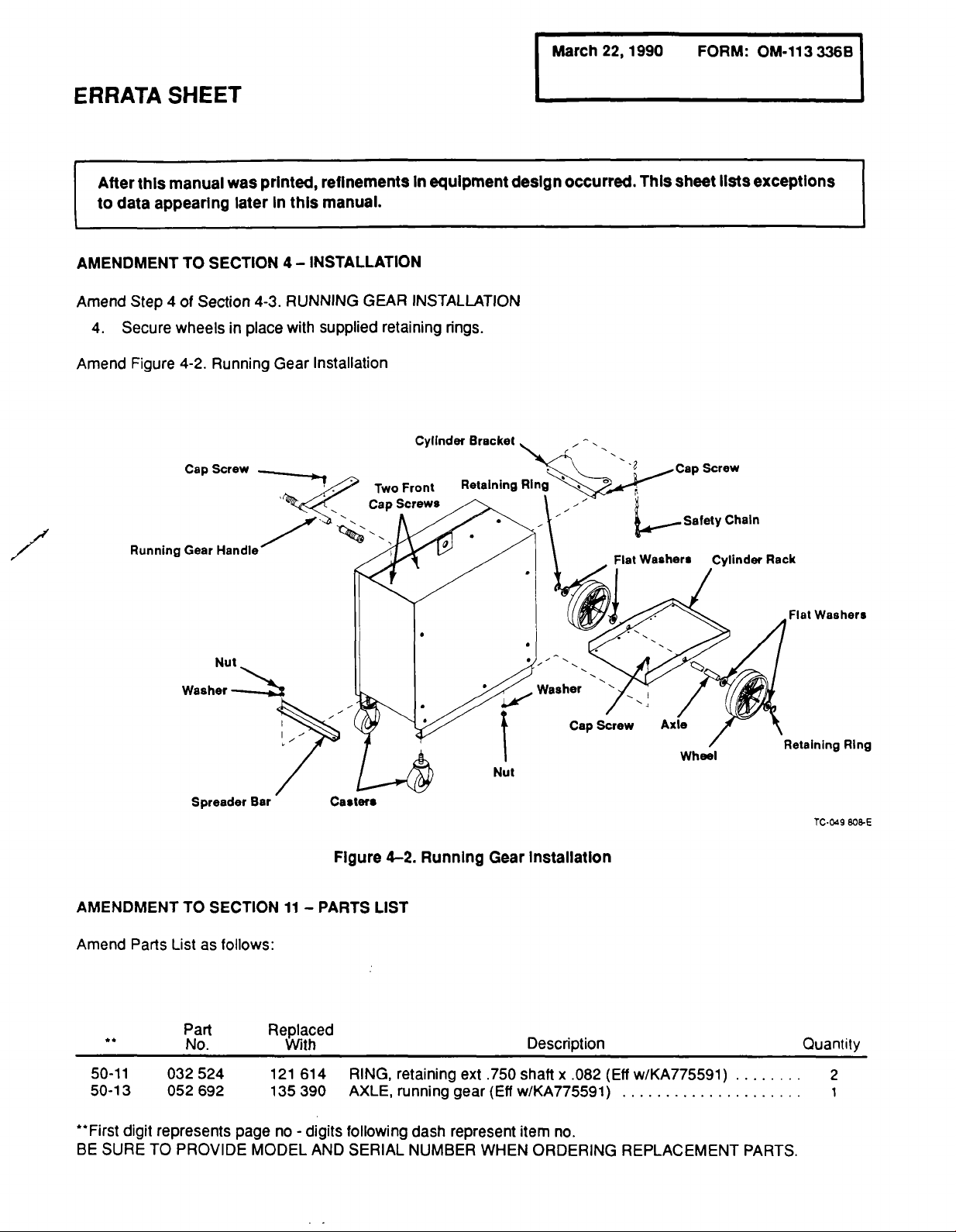
Secure
4.
Amend
manual
this
appearing
4
Step
Figure
TO
of
Section
wheels
4-2.
Cap
was
later
SECTION
in
place
Running
Screw
printed,
In
this
4-
RUNNING
4-3.
with
Gear
refinements
manual.
INSTALLATION
GEAR
supplied
retaining
Installation
Two
in
equipment
INSTALLATION
rings.
Cylinder
Front
Bracket
design
occurred.
This
sheet
Screw
lists
exceptions
Rack
AMENDMENT
Amend
**
50-11
50-13
Parts
TO
List
Part
No.
032
052
Nut
Spreader
SECTION
follows:
as
524
692
Bar
11
Replaced
With
121
135
614
390
Casters
Figure
PARTS
LIST
RING,
AXLE,
42.
Running
retaining
running
ext
gear
Nut
Gear
installatIon
Description
.750
shaft
(Eft
w/KA775591)
x
Screw
Cap
.082
(Effw/KA775591)
Wheel
Retaining
TC.049
Quantity
2
I
Ring
808-E
**First
BE
SURE
digit
represents
TO
PROVIDE
page
no
MODEL
-
digits
AND
following
SERIAL
dash
NUMBER
represent
WHEN
item
no.
ORDERING
REPLACEMENT
PARTS.
Page 4

Page 5
RECEIVING-HANDLING
Before
age
claims
Assistance
from
ers
When
ways
unpacking
that
may
for
loss
for
the
distributor
Transportation
requesting
provide
Number.
Section
SECTION
equipment,
have
occurred
or
damage
or
filing
and/or
Department.
information
the
Model
No.
1
1-1.
1-2.
1-3.
1-4.
check
during
with
settling
claims
the
about
Description
SAFETY
Introduction
General
Arc
Welding
Standards
carton
shipment.
the
deliverIng
may
equipment
this
equipment,
and
Serial
RULES
Precautions
Booklet
forany
dam-
File
carrier.
obtained
be
manufactur-
or
Style
TABLE
FOR
OPERATION
Index
any
al
OF
the
Use
tion
mationislocated
Model
Serial
Date
following
Serial
and
________________________________________
or
Style
of
Purchase
CONTENTS
OF
ARC
or
spaces
Style
the
on
to
Number
data
record
card
of
the
your
or
Model
the
unit.
nameplate.
No._____________________________
______________________________
No.
Page
WELDING
POWER
SOURCE
1
1
3
5
Designa
The
infor
SECTION
SECTION
SECTION
2-1.
2-2.
3-1.
3-2.
3-3.
3-4.
3-5.
3-6.
3-7.
4-1.
4-2.
4-3.
4-4.
4-5.
4-6.
4-7.
4-8.
4-9.
4-10.
4-11.
4-12.
4-13.
2-
SAFETY
General
Safety
3
Alert
INTRODUCTION
Volt-Ampere
Duty
Cycle
Description
Supplied
Additional
Optional
Consumable
4
INSTALLATION
Site
Selection
Transporting
Running
Optional
Shielding
Work
Cable
Weld
Polarity
MWG-200
Installation
Welding
Hub
Tension
Electrical
Welding
PRECAUTIONS
Information
Symbol
Curves
Equipment
Required
Equipment
Parts
Methods
Gear
Installation
SPW-1
Gas
Panel
Installation
Assembly
Selection
Welding
Of
Optional
Wire
Spool
Adjustment
Connections
Input
Wire
Threading
AND
And
Safety
And
Signal
Equipment
Installation
Gun
Connections
Spool
Installation
Gun
SIGNAL
Words
WORDS
..
6
6
8
8
8
8
9
10
10
10
10
11
11
12
13
14
14
15
16
16
16
17
Page 6
Section
No.
Page
No.
SECTION
SECTION
SECTION
5-1.
5-2.
5-3.
5-4.
5-5.
6-1.
6-2.
6-3
7-1.
7-2.
7-3.
7-4.
7-5.
7-6.
7-7.
7-8.
7-9.
OPERATOR
5
Power
ThicknessNolts
Fine
Switch
Tuning/Wire
Fan-On-Demand
Optional
SEQUENCE
6
Gas
And
Gas
(Models
Shutting
7-
MAINTENANCE
Routine
Replacing
Drive
Replacing
Inspecting
Overload
Thermal
Printed
Spot
Metal
Gas
Metal
Metal
With
Down
Maintenance
Housing
Hub
Protection
Overload
Circuit
Arc
Arc
Drive
And
Troubleshooting
CONTROLS
And
Pilot
Light
Selector
Speed
Pulse
OF
OPERATION
Welding
Arc
Welding
Optional
&
Roll
Control
Panel
(GMAW)-Continuous
Welding-Pulsed
(GMAW)-Spot
SPW-1
TROUBLESHOOTING
And
Realignment
Assembly
Replacing
Protection
Board
Replacement
Controls
Panel
Wire
Inlet
Motor
Arc
Only)
Guide
Brushes
(GMAW-P)
19
19
19
19
19
20
22
23
23
24
26
26
26
27
27
27
27
SECTION
SECTION
SECTION
8-
Diagram
Diagram
9
9-1.
9-2.
9-3.
9-4.
9-5.
9-6.
10
10-1.
10-2.
10-3.
10-4.
10-5.
10-6.
ELECTRICAL
8-1.
Circuit
8-2.
Circuit
WELDING
Gas
Metal
Gas
Metal
Gas
Metal
Welds
Plug
Skip
Welding
Troubleshooting
AUTO
Pointers
Procedure
Procedures
How
To
Prevent
Procedures
Welding
Diagram
Diagram
TECHNIQUES
Arc
Arc
Arc
BODY
For
Welding
For
For
For
Frames
DIAGRAMS
Welding
Welding
Welding
The
REPAIR
Welding
Welding
Glass
Welding
And
SPW-1
For
&
Panel
TROUBLESHOOTING
(GMAW)Continuous
(GMAW)-Pulsed
(GMAW)-Spot
Gas
Metal
Arc
Welding
APPLICATION
Auto
Mild
Door
Breakage
Fenders
High
Sheet
Body
Steels
Panels
And
And
Strength
(HSS)
Process
Metal
Spatter
Quarter
Steels
Seam
On
Panels
Windows
30
30
31
32
33
34
34
34
37
37
37
38
38
38
Page 7
Section
SECTION
LIST
No.
11
Figure
Figure
Figure
Figure
Figure
Figure
Figure
Figure
OF
CHARTS
Table
Chart
Chart
Table
Table
(GMAW)
Table
Table
Table
PARTS
11-1.
11-2.
11-3.
11-4.
11-5.
11-6.
11-7.
11-8.
3-1.
3-1.
3-2.
3-2.
6-1.
6-2.
7-1.
7-2.
LIST
Main
Assembly
Baffle,
Drive
Assembly,
Panel,
Panel,
SPW
1
Circuit
Running
AND
TABLES
Specifications
Volt-Ampere
Duty
Cycle
Conductor
Input
Suggested
Checking
Maintenance
Troubleshooting
-
Air
W/Components
-
Rear
Front
Card,
W/Components
-
W/Components
Panel
Spot
PC5O
Gear
Curves
And
Parameters
Parameters
Weld
Schedule
Wire
(Optional)
Fuse
For
Size
Continuous
Gas
Metal
Arc
Welding
Page
40
42
44
45
46
48
49
50
21
23
23
28
No.
7
7
7
17
Page 8

Page 9
SECTION
1
SAFETY
RULES
FOR
OPERATION
OF
ARC
WELDING
POWER
SOURCE
1-1.
INTRODUCTION
We
learn
by
experience.
sonal
experience,
harmful,
teach
ers
Safe
practices
welding
search,
evolved
and
tion,
wasteful,
you.
and
development,
reliable
servicing
likeachild
and
developed
cutting
are
equipment
practices.
unwise.
describedinthis
equipmentisimproperly
for
the
son
Some
technical
rules.
Read
tempting
Comply
ticular
personal
Failuretoobserve
ous
injury
equipment
These
1-General
and
ting;
Reference
also
are
cedures
in
the
most
The
National
Health
inspection
ment
1-2.
Different
and
fluxes
radiation
manual,
facturers
specIfic
concerning
A.
Burn
Wear
in
use
shirt
collar
avoid
to
Wear
shields
(protected
safe
practices
based
are
volumes
and
to
with
equipment
safety
safe
on
understand
install,
these
used
and
these
death.
or
be
can
practices
common
to
operate,
procedures
used
Precautions,
2-Arc
Welding
standards:
those
for
given
Index
available
than
Standards
complete.
Electrical
Administration,
requirements
installation,
GENERAL
arc
levels.
be
MaterIal
technical
Prevention
protective
welding,
and
entry
helmet
use,
PRECAUTIONS
welding
can
produce
In
to
sure
data
their
material.
clothing-gauntlet
hat,
pocket
of
sparks
with
safety
underneath,
clear
by
explain.
these
and
for
the
When
with
are
common
(and
Published
additional
in
Code,
local
and
processes,
addition
consult
Safety
and
and
flaps,
and
appropriate
cover
Learning
from
and
and
usedormaintained.
may
theirinstruction
safety
safe
safety
divided
safety
touching
Let
the
experience
experience
field
experience
safe
installation,
Accidents
not
always
sense,
or
others
Itiswiser
safe
practices
service
as
applicable
of
others.
practices
becomes
confidence.
into
to
arc
Cutting)
through
a
in
manual.
occur
to
the
may
two
welding
(only).
Standards
and
more
in
this
this
manual.
manual.
complete
They
ANSI
Occupational
industrial
also
provide
service.
different
to
flux
Data
electrode
fumes,
the
Information
and
Sheets
codes,
basis
a
electrode
(MSDSs)
precautionary
high
safety-toe
and
gloves
wear
designed
shoes.
cuffless
slag.
goggles
and
filter
glass).
glasses
This
lenses
isaMUST
hot
stove
oth
of
the
use
Re
have
opera
per
when
The
rea
be
given.
require
may
follow
before
the
at
equipment.
the
to
par
manuals,
cause
a
Z49.1is
Safety
for
seri
the
habit,
Sections:
and
cut
on
safety
pro
listed
are
the
and
and
local
for
equip
alloys,
In
manu
measures
Button
trousers
with
or
plates
and
this
for
for
side
for
gases,
is
of
welding
from
glass
Avoid
Hot
should
Medical
a
shift
treatment
Ear
in
others
or
radiant
when
or
oily
metal
never
first
unless
of
should
plugs
confined
work
first
qualified
a
Flammable
sons
intending
B.
Severe
fumes,
that
adequate
Z49.1
oxygen.
Lead
ing
duce
local
the
plied
Metals
fumes
from
Fume
Toxic
discomfort,
vapors,
welding
ventilationasdescribed
listedinStandards
-,cadmium-,
and
similar
harmful
exhaust
area as
respirator.
coated
should
the
work
necessary,
in
Work
and,
tor.
Gas
Leaked
centration
confined
Leaving
to
prevent
downstream
left
a
if
necessary,
leaks
gas
confined
open.
confined
dangerously.
space.
possible
Check
re-entering
the
The
from
heat
toxic
ultraviolet
Vapors
by
highly
ucts.
decompose
form
vapors
solvent
to
vapors
atmosphere
(and
cutting,
energy
broken,
greasy
such
as
be
handled
and
aid
aid
medical
flash
burnsofthe
be
space.
overhead.
hair
preparations
weld
to
Prevention
heat,
(orcutting)
materials,
concentrationsoftoxic
ventilation
well
as
For
with
be
not
surface,
while
wearinganair-supplied
while
in
confined
a
in
large
space,
valves
to
it.
chlorinated
of
the
and
gas,
chipping)
and
flying
pitted,orspattered.
clothing.
electrode
eye
person
facilities
worn
A
illnessordeath
or
zinc-,
the
beryllium,
A
without
treatment.
should
are
eyes
when
hard
hat
should
cut.
or
oxygen
produce.
may
Index.
mercury-,
when
be
must
operator
both
orcontaining
heated
space
unless
the
area
onlywhile
wearing
space
Do
not
OFF
shut
been
that
solvents
flame)
lung
energy
can
bring
quantities
accumulation
have
be
sure
arc
(or
other
(radiant)
trichloroethylene
DO
phosgene.
be
can
or
where
drawn
the
NOT
into
radiant
to
protect
metal.
spark
stubs
Replace
See
Ignite
may
and
workpleces
1-3A.2.
gloves.
First
aid
facilities
available
be
close
working
should
enrichment
NEVER
welded
used,
must
materials
is
for
immediate
by
and
skin
overhead
on
be
worn
be
used
not
result
can
or
Prevent
in
ANSI
ventilate
and
beryllium-bear
(or
cut)
fumes.
each
or
wear
an
be
must
used.
that
coating
well
is
ventilated
respirator.
it
is
being
an
air-supplied
should
change
gas
of
gases
accidentally
the
space
can
form
to
and
and
WELD
the
energy
be
oxygen
cylinders
gas
supply
in
the
opened
is
safe
be
decomposed
PHOSGENE,
irritating
eye
of
the
arc
perchloroethylene
or
welding
can
113336
the
eyes
cover
them.
and
for
each
burns.
or,
when
by
per
from
depletion
them
with
Standard
with
may
pro
Adequate
person
in
air-sup
emittoxic
removed
if
and,
ventilated
respira
avoided.
con
into
a
at
source
if
space
or
before
a
prod
also
can
cut
where
or
cutting
penetrate
1
Page
Page 10
to
atmospheres
trichloroethylene
C.
Fire
and
Causes
bythe
rial;
short
BE
through
and
goggled
To
Keep
and
cause
If
the
Avoid
lators.
at
protect
fire-resistant
Walls
not
work
shields.
Fire
guishing
ing
of
fire
flame,
arc,
misuse
circuits.
AWARE
cracks,
through
operator.
prevent
equipment
electrical
(in
short
combustibles
if
work
nt
pai
If
the
least
35
against
touching
be
welded
should
watcher
equipment
or
cutting
a.
appreciable
containing
or
Explosion
and
explosion
flying
of
compressed
THAT
flying
along
wall
or
Sparks
fires
and
clean
parts)
circuits.
are
practicable,
rooms,
spray
work
cannot
feet
away
ignition
covers
combustibles
on
(or
be
protected
must
be
if:
construction)
b.
appreciable
feet
but
can
c.
openings
within
(concealed
35
feet
sparks
d.
combustibles
metal
Hot
work
ensure
have
been
After
work
glowing
An
empty
produce
be
never
been
cleaned
7
in
Standards
This
includes:
solvent
bles
solubility)
trogen
113
336
Page
or
conducted
permit
supervisors
embers,
container
flammable
welded
water
or
carbon
or
partitions
should
taken.
is
done,
and
on
describedinAWS
as
Index.
a
thorough
washing,
followed
dioxide,
2
heat.
minute
even
perchloroethylene.
Prevention
combustibles
are:
sparks,
gases
hot
slag
and
or
sparksorfalling
slag
windows
out
can
fly
pipes,
floor
through
openings,
and
explosion:
and
operable,
metallic
of
in
out
or
cut).
do
area,
to
an
tanks,
dip
be
moved,
of
reach
with
shields.
Walls,
area
suitable
on
by
standing
and
during
combustibles
within
are
combustibles
be
ignited
orvisible)
may
expose
adjacent
can
be
obtained
approvalthat
check
that
or
flames.
held
toxic
or
cut,
steam
that
combustibles,
vapors
unless
depending
by
purging
and
free
particles
NOT
weld
free
of
storage
move
of
sparks
and
opposite
ceilings,
heat-resistant
with
some
suitable
time
by
for
(including
35
feet
further
are
by
sparks
in
combustibles
to
walls,
be
ceilings,
ignited
before
adequate
is
area
orcaustic
using
free
when
container
Standard
on
and
inerting
protective
amounts
reached
heated
cylinders;
slag
of
of
combustibles.
can
or
sight
35
feet.
oil,
cut.
or
areas,
mate
pass
doors,
of
grease,
that
Move
venti
and
the
can
combustibles
and
heat;
snug-fitting,
sides
should
and
floor
near
covers
fire
extin
afterweld
building
than
35
floors
orwalls
roofs,
radiant
by
operation
precautions
of
sparks,
that
or
heated,
A6.O,
cleaning
the
must
has
listed
(or
combusti
with
can
first
ni
equip-
or
to
or
to
of
or
a
ment
working
A
container
(see
smell
Hollow
welding
Explosive
may
as
D.
Standard
manual,
HANDLING
DERS,
1.
Regulator
regulator
any
with
Never
other
Remove
pair
indicate
Leaks-if
Excessive
with
Faulty
when
release.
Repair.
for
where
recommended
as
level
with
preceding
or
sight
castings
or
cutting.
atmospheres.
contain
gasoline).
Compressed
precautions.
andthose
listed
Pressure
relief
from
downstream
one
or
connect
than
more
that
faulty
close
(first
a
faulty
gas
Creep-if
downstream
Gauge-if
pressurized,
Do
NOT
repair
to
special
personnel.
2.
Cylinders
Cylinders
and
Avoid
third
produce
dent.
ICC
assurance
dled.
Identifying
gas
content.
alter
or
is
illegal
Empties:
mark
must
damage
electrical
electrical
rails,
short
(See
DOT
or
marked
Notify
name,
and
Keep
MT;
keep
1-3C.)
of
gas
on
promptly.
in
A6.O.
Waterfilling
substitute
may
unknown
paragraph).
determineifitissafetoweld
to
containers
or
They
flammable
Gas
detailedinCGA
COMPRESSED
OF
in
11
Standards
for
contents
NOT
Do
must
can
explode.
Neverweld
dust,
gas,
Equipment
Comply
with
Index.
inerting.
or
Standard
Regulators
valve
is
designed
it
is
overpressure;
equipment.
relief
devices.
a
regulator
for
which
the
regulatorfrom
cylinder
valve).
not
Provide
to
a
cylinder
regulator
service
The
regulator:
leaks
externally.
delivery
valve
gauge
nor
attempt
manufacturers
techniques
be
handled
their
to
walls,
circuit
wires,
circuit
arcs
them;
must
when
do
marking
safety
content.
supplier
number,
hazardous.
valves
them
separate
pressure
closed.
pointer
returns
to
repair.
and
carefully
valves,
contact
or
welding
that
be
the
Use
only
not
rely
if
unmarked.
other
or
closed,
does
to
stop
Send
designated
tools
with
lead
may
each
on
cylinder
cylinders
on
markings
replace
from
below
just
shouldbecleaned
on
vented
where
vapors
sense
or
cut.
before
the
(such
in
depend
be
orcut
liquid
precautions
P-1,SAFE
GASES
to
intended
IN
protect
to
such
protection
CYLIN
only
protect
containing
was
designed.
immediatelyfor
following
not
pin
are
or
safety
cylinders
circuits.
color
NEVER
FULLS
symptoms
continues
off
move
after
pressure
faulty
regulators
repair
used
by
to
prevent
devices:
including
They
to
serious
a
cylinder.
is
properly
with
name
to
identify
DEFACE
on
a
cylinder.
caps
securely;
and
to
stop
center,
trained
leaks
It
return
this
the
gas
re
rise
pin
can
acci
is
an
han
gas
of
air
of
It
Page 11
Prohibited
other
than
roller.
Locate
over.
or
Passageways
where
areas
Transporting
such
port
the
ground
or
magnets.
NOT
Do
and
stag,
contents
low
supplier.
Mixing
Never
such
cylinders
objects,
moving
valve.
valve
gases.
refill
where
Protect
falling
when
Stuck
cylinder
your
Cylinderfittings
Hose
3.
Prohibited
for
the
specified
is:
red
for
gases.
Use
ferrules
wireorother
nary
hoses
to
No
copper
to
tings
Avoid
hose
on,
splice
long
off
otherwise
or
Never
use.
intended
its
secure
cylinders
and
they
cylinders.
a
as
platform
their
by
expose
flame,
etc.
exceed
to
exposure
and
cylinders.
NOT
Do
that
Never
cylinder.
any
should
Never
use.
gas.
fuel
gas,
or
clamps
fittings.
tubing
hose.
to
runs
ground
to
damaged.
a
use
cylinder
NEVER
use,
so
they
work
areas.
struck.
be
may
With
a
crane,
orcradle.
valves
cylinders
particularly
can
green
or
that
may
130F.
exists.
weather.
use
a
not
to
try
never
hose
use
A
general
for
caps,
excessive
to
cause
valves
hammer
be
mix
be
oxygen,
designed
it
as
Use
kinks
from
substitute)
splices.
prevent
keep
or
as
cannot
Keep
cylinders
use
NOT
Do
or
by
rupture.
with
Cool
from
Replace
wrench
or
opened
gases
any
modified
otherthan
hose
identification
and
for
the
a
binding
standard
only
and
run
being
its
contents
a
support
be
a
secure
lift
cylinders
chains,
heat,
water
bumps,
caps
hand.
by
in
a
or
exchanged.
that
black
hose
to
abuse.
over,
for
or
knocked
of
clear
sup
off
slings,
sparks,
Do
al
not
spray
falls,
securely
to
open
Notify
cylinder.
designed
rule
inert
for
ordi
(not
connect
brass
fit
Suspend
stepped
outlet
with
a
Match
the
that
thatthe
CONNECT
gases
Tighten
nections,
Tighten.
retighten
Adapters.
plier)
two
use
LEFT
Regulatoroutlet
by
right
(with
5.
a
Pressurizing
Drain
fore
opening
justing
sive
compression
seat
engaged
Stand
Open
creases
reaches
lowing
seal
to
less
Use
safe
regulators.
Check
there-after.
uid*
leak.
bustible.
from
away
clean
lintless
regulator
regulator
regulator
a
to
a
cylinder
connections.
clean
If
connection
using
Use
between
wrenches
HAND
threads.
hand
grooved
regulator
cylinder
screw
to
open
slightly
side
to
cylinder
slowly.
regulator
position:
stem
against
than
one
pressure
and
efficient,
for
leaks
Brush
or
equivalent
Clean
off
people
to
label
inlet
regulator
and
cloth.
cylinder.
and
and
cylinderoutlet
designed
containing
When
smooth
and
leaks,
adapter
and
to
tighten
hose)
for
nut
on
fitting
connections
oxygen
or
properly
CGA
a
cylinder
(or
threads
hex
Steps:
of
residual
in
(clockwise).
heat
on
pressurization.
on
of
regulator
valve
When
gas
manifold
(or
at
high
single-stage
while
so
slowly
gauge
maximum)
For
oxygen,
possible
turn
to
permit
charts
soapy
(available
recommended
first
on
with
per
pressurization
soap
gallon
water
sources
Before
cylinder
any
of
connecting,
marking
for
a
particular
other
assembling
where
seats
disassemble,
wrench.
(available
and
if
marked
may
left
for
regulator,
adapter
shank)
through
valve)byturning
Draining
pressure
Leave
regulators.
opening
that
regulator
is
pressurized
leave
cylinder
and
inert
leak.
For
quick
emergency
from
your
pressure
solution
of
after
(capfull
water).
dried
test;
ignition.
area,
match.
NEVER
gas.
threaded
necessary.
clean,
from
your
is
one
required.
RIGHT
be
identified
hand
threads
fuel
gas.
suitable
vent
prevents
seat
by
allowing
adjusting
cylinder
pressure
valveinfol
gases,
fuel
open
gas,
shutoff.
supplier)
settings
and
regularly
of
Ivory
Bubbles
soap
Wipe
check
and
or
gas
con
and
sup
and
be
ad
exces
screw
valve.
in
(gauge
fully
to
open
for
on
Liq
indicate
is
com
Coil
excess
Protect
sparks,
Examine
nections.
dicate
leaks.
Repair
ing
(1-2D3).
4.
Proper
Clean
cylinder
orifices
Except
hose
hose
and
slag,
hose
Immerse
or
leaky
Do
Connections
and
damage
for
hydrogen,
to
prevent
from
damage
open
regularly
pressured
hose
worn
NOT
tape.
valve
outlet
seats
crack
flame.
for
leaks,
by
before
valve
kinks
and
by
sharp
wear,
in
hose
cutting
of
impurities
connecting
momentarily,
tangles.
edges,
and
water;
out
area
that
and
by
loose
con
bubbles
and
may
in
splic
clog
regulator.
pointing
E.
User
Responsibilities
Remove
mediately
in
F.
Close
G.
Rope
cutting
leaky
for
equipment
Leaving
supply
gas
Rope
Staging-Support
staging-support
operation;
*Trademark
1-3.
ARC
WELDING
defective
or
repair.
See
manual.
EquIpment
at
source
rope
of
Proctor
User
Unattended
should
may
&
Gamble.
equipment
from
Responsibility
and
drain
gas.
be
not
used
burn.
service
statement
for
welding
113
336
Page
im
or
3
Page 12
Comply
Arc
careless
high
bright
frared
pressed
unnecessary
accidents.
dards
A.
Comply
The
can
from
Skin
shielded
BURNED;
1.
Wear
arc)
essary,
Ieatherjacket
sistant
ton.
Bare
Button
ets
2.
Protect
electric
Welding
no.
face
Protect
Cracked
worn;
Cracked,
IMMEDIATELY.
pitted,
Flash
the
helmet
struck.
eyes
cause
area
3.
Enclosed
rate
round
ble
ticularly
113
with
precautions
Welding,
properly
operator
currents
and
hot.
energy
gases
risks
Precautions
referenced
Burn
Protection
with
precautions
welding
damage
arc
eyes,
light-colored
burns
resemble
are
arcs
COMPLY
Protective
long-sleeve
in
addition
additional
use
or
leggings.
skin
protection.
collar
to
to
prevent
Head
and
Eye
from
eyes
without
arc
helmet
12
denser
or
before
striking
filter
plate
broken
or
radiation
broken,
or
spattered.
goggles
helmet
not
to
give
be
Looking
(particularly
retinal
a
in
the
fieldofvision.
Protection
welding
or
the
operation
or
floor
at
4
Page
enclosed
room
screens
336
done,
invites
at
significant
Sparks
fly,
radiates,
be
and
in
index.
intense
used.
protects
are
may
is
penetrate
surfaces,
acute
more
severe
WITH
Clothing
clothing
to
gloves,
sleeves,
Avoid
outer
Wear
protect
entry
chest
of
sparks.
Protection
exposure
protection.
shield
or
must
be
arc.
with
a
helmet
can
pass
loose
or
Replace
with
side
some
lowered
at
burn
of
protection
an
arc
a
high
that
Nearby
area.
bay
with
panels.
Allow
level.
in
1-1,
is
trouble.
1-2,
safe
a
The
equipment
and
voltages.
fumes
weidments
The
described
1-2.
in
and
visibly
rise,
are
wise
himself
bright.
ultraviolet
here
lightweight
and
burn
the
sunburn,
and
PRECAUTIONS.
those
painful.
(particularly
and
hat,
protective
flame-proof
shoes
clothing
apron,
garments
substantial
dark,
and
to
containing
used
when
clear
cover
or
through
filter
plates
clear
cover
shields
the
over
momentarily
intensity
leave
may
Personnel
For
production
is
best.
and
neck
NEVER
arc.
filter
a
welding.
plate.
shield
to
cause
must
plate
MUST
the
to
face
with
gas-shielded
a
In
open
low-reflective,
for
free
air
this
section.
arc
and
others
and
Its
radiation
and
from
DONT
such
and
but
carries
is
very
and
com
avoids
from
in
stan
reflect
eyes.
gas-
GET
As
nec
fire-re
process,
The
hot,
operator
and
clothing,
skin
for
gas-shielded
(1-2A).
of
untreated
clothing.
button
pock
look
at
shade
plate
Pace
over
should
eyes
before
when
be
NOT
burns.
be
replaced
broken,
worn
should
an
under
arc
unprotected
arc)
a
areas,
dark
sepa
permanent
welding,
non-combusti
circulation,
in
cot
the
can
sur
par
as
an
be
is
Viewing
who
a
Others
flash
Before
bay
B.
Comply
Generator
air.
C.
Comply
the
will
be
working
goggles.
starting
doors
are
Toxic
Fume
with
engine
Carbon
Fire
and
with
looking
monoxide
Equipments
equipment.
Loose
cause
Never
sel.
ture
D.
Comply
E.
Exposed
ing
ment
conductor.
TOUCH
cable
fire.
a
strike
It
creates
lead
or
Compressed
with
can
Prevention
hot
or
fatally
DO
wet
a
Shock
circuit,
Provide
weld.
directly
in
area.
to
weld,
closed.
PreventIon
precautions
exhaust
Explosion
precautions
rated
capacity.
It
overheat
may
connections
on
an
arc
brittle
a
such
to
Gas
precautions
conductorsorother
in
ungrounded,
shock
NOT
surface
See
make
in1-2B.
must
kill.
can
Prevention
in
a
cylinder
area
a
rupture
Equipment
in1-2D.
a
person
STAND,
when
face
shields
weld.
the
at
all
that
may
that
sure
be
1
-2C.
Do
not
cables
can
under
persons
that
vented
overload
and
overheat
other
or
cause
rough
bare
electrically-HOT
whose
SIT,
LIE,
welding,
for
screen
to
cause
or
pressure
a
metal
body
LEAN
without
all
persons
are
wearing
or
flaps
the
outside
arc
welding
fire.
a
flash
and
ves
violent
rup
handling.
the
in
weld
equip
becomes
OR
ON,
suitable
a
protection.
To
protect
Wear
body
adequate
duckboard,
dry
can
tween
metal
able
through
A
voltage
ducting
ing
objects
trical
against
dry
insulating
and
clothing
insulation
be
not
avoided.
body
reduces
dangerous
the
will
object
include,
work
tools,
workpieces,
metal
object
1.
Grounding
Arc
welding
the
National
grounded
And
When
welding
culatorto
quate
according
Cutting.
installing,
power
the
to
carry
shock:
gloves
dry.
against
rubber
or
Sweat,
and
an
electrically
the
electrical
and
body.
exist
between
in
the
work
but
benches,
Never
etc.
unless
the
Equipment
the
equipment
Electrical
to
connect
source,
building
ground.
ground
and
Never
work
electrical
when
mat
sea
resistance,
possibly
the
circuit.
limited
not
are
welding
touch
welding
must
be
Code,
ANSI
Z49.1
the
frames
control,
currents
worktable,
Conductors
body
in
damp
dampness
water,
HOT
part
lethal
electrode
Examples
to,
power
the
electrode
power
grounded
and
the
Safety
of
each
safely.
Equipment
protection.
area
shock.
moisture
or
or
and
currents
and
buildings,
source
source
Keep
without
Stay
or
sweat
grounded
could
to
any
of
conduct
elec
cases,
and
is
according
work
must
In
Welding
unit
such
andwater
be
must
made
on
be
en
flow
con
any
off.
cir
ade
a
to
be
as
Page 13
electrically
tally.
carrying
HOT
NOTGROUNDto
Do
ANY
Three-phase
equipment
available,
wires
ment
ment
tion
that
Before
conductors
frames
If
line
a
equipment
ground
plug
ceptacle,
ground
prong
Never
plug
2.
Electrode
Fully
NOT
3.
Connectors
Fully
join
welding
4.
Cables
Frequently
IMMEDIATELY
or
damaged
from
taped
Keep
from
5.
Terminals
Terminals
should
6.
a.
before
connect
of
the
ground
will
become
can
welding,
connections.
at
cord
for
leadtothe
is
added
the
prong
plug,
remove
broken
with
a
insulated
holders
use
insulated
inspect
bared
cable.
to
give
cable
hot
metal
and
have
Electrode
Equipment
3-phase
are
connect
cable
dry,
insulating
Welding
metal
welding
mally
off
control
equipped
cally
and
touch
ject
the
welding
b.
Equipment
contactor)
stray
current
by
electrical
flammable
or
gas
connection.
Check
installing.
single-phase
Do
line.
lead
to
the
third
electrically
shock,
possibly
check
touching
with
a
ground
connection
grounded
for
connection
ground
If
only.
Holders
the
to
the
ground
off
electrode
with
lock-type
ground
bare
to
switchbox.
must
lead
line
a
grounded
prong
ground
holders
protruding
connectors
lengths.
cables
REPLACE
insulationtoavoid
Cables
resistance
free
and
And
other
power
arc
welding
(GTAW)
are
equipped
of
the
HOT
when
the
welding
the
electrode
in
contact
forwear,
those
with
equivalenttooriginal
of
oil
and
sparks.
Other
Exposed
exposed
covers
with
output
sources
(GMAW),
and
with
the
welding
electrode
the
power
gun
wire
with
the
power
without
source
shock,
may
conduit,
such
liquid
phase
requirements
If
only
3-phase
equipment
NOT
connect
or
wire,
(live)
HOT-a
dangerous
fatally.
for
continuity.
metal
lead
a
switchbox,
to
a
be
cord
of
is
provided
If
a
grounded
connected
comes
mating
from
a
plug,
prong.
should
screws.
shouldbeused
cracks
with
excessively
possibly-lethal
Parts
of
electrical
before
control
use
gas
processes
that
output.
becomes
source
is
conducting
any
is
off.
on/off
areas
and
closed.
damaged
grease,
parts
secured
on/off
for
similar
devices
power
wire
switch
or
electrode
output
possiblyfa
orto
a
pipe
oil
fuel.
or
as
of
equip
equip
condi
Be
is
two
sure
to
the
the
power
only
equipment
with
the
connect
the
three-prong
to
re
the
mating
withathree-
receptacle.
or
use
be
used.
Do
to
and
damage.
worn
shock
be
may
cable.
protected
units
operation.
(contactor)
with
the
gas
When
electri
is
Never
unless
arc
nor
on
so
ON
ob
(no
tungsten
permit
switch
circuit
control
a
Welding
metal
esses
output
ment
power
electrode
off.
7.
Safety
Safety
should
Before
shut
switches)
tag
Disconnect
all
pull
Do
not
ing.
against
Leaving
disconnect
Power
welding
F.
port
Magnetic
Devices
devices
be
not
installation,
OFF
all
115
volts
open
in
an
It,
shock
equipment
all
disconnect
power
Protection
Devices
fields
operation.
equipment
before
(pacemaker)
going
operations.
1-4.
STANDARDS
For
more
information,
their
latest
revisions
1.
ANSI
Standard
CUTTING
Society,
2.
NIOSH,
AND
GAS
from
the
ernment
3.
OSHA,
29CFR
Documents,
Washington,
4.
ANSI
Standard
OCCUPATION
FACE
PROTECTION
National
NY
York,
5.
ANSI
Standard
SAFETY-TOE
American
New
way,
6.
ANSI
Standard
USE
OF
power
arc
may
on-off
electrode
the
switchisturned
suchasinterlocks
disconnectedorshunted
power
to
prevent
cables
alt
line-cord
power
emergency,
burns,
power
source.
For
sources
welding
not
unless
be
equipped
control
the
(SMAW)
devices.
is
electrically
welding
inspection,
and
remove
accidental
from
welding
plugs.
circuit
or
change
it
must
from
flash
or
unattended.
to
equipment.
switch
must
Wearers
or
line
be
of
(Pacemakers)
from
Persons
near
obtainable
N.W.
550
SAFETY
WELDING
Superintendent
Printing
SAFETY
obtainable
1910,
D.C.
Standards
10018.
National
York,
CUTTING
high
wearing
arc
welding,
BOOKLET
refer
and
Z49.1,
LeJeune
AND
Office,
U.S.
20402.
Z87.1,
AND
Z41.1,
FOOTWEAR
NY
Z49.2,
currents
electronic
should
consult
gouging,
the
to
comply
SAFETY
from
HEALTH
AND
of
Washington,
AND
HEALTH
from
Government
SAFE
EDUCATIONAL
obtainable
Institute,
STANDARD
Standards
10018.
FIRE
AND
WELDING
with
used
similar
and
with
welding
With
such
HOT
ON.
Never
power
and
circuit
out.
service,
of
fuses
(or
turning
power
polarity
equipment,
lock
ON
source,
while
disconnected,
switch
Always
be
Electronic
can
INDEX
following
as
the
Rd,
arcing.
shut
available
affect
pacemaker
life
with
their
or
spot
standards
applicable:
IN
WELDING
American
Miami,
IN
ARC
CUTTING
Documents,
D.C.
STANDARDS,
the
Superintendent
Printing
PRACTICES
from
the
1430
Broadway,
FOR
obtainable
Institute,
PREVENTION
1430
PROCESSES
shielded
proc
power
equip
when
the
touch
the
source
breakers
red-
or
of
power.
and
weld
guard
OFF
and
the
near
Life
Sup
support
doctor
welding
AND
Welding
FL
33126.
WELDING
obtainable
U.S.
Gov
20402.
Office,
FOR
EYE
AND
American
New
MENS
from
the
Broad
IN
THE
is
or
of
113
336
Page
5
Page 14

obtainable
Institute,
AWS
7.
CONTAINERS
TIBLES
ciety,
NFPA
8.
TEMS
PROCESSES
Protection
MA
NFPA
9.
CODE
Association,
02269.
10.
NFPA
PROCESSES
Protection
MA
11.
CGA
PRESSED
1430
Standard
obtainable
N.W.
550
Standard
FOR
Association,
02269.
Standard
obtainable
Standard
Association,
02269.
Pamphlet
the
American
from
Broadway,
A6.0,
WHICH
from
LeJeune
51,
WELDING,
obtainable
70,
from
Batterymarch
51B,
obtainable
P-i,
GASES
National
New
York,
WELDING
HAVE
the
Rd,
OXYGEN-FUEL
HELD
American
Miami,
CUTTING,
the
from
Batterymarch
NATIONAL
National
the
Park,
CUTTING
the
from
Batterymarch
SAFE
IN
HANDLING
CYLINDERS
Standards
NY
AND
CUTTING
COMBUS
Welding
FL
33126.
GAS
AND
National
Park,
ELECTRICAL
Protection
Fire
Quincy,
WELDING
AND
National
Park,
obtainable
10018.
ALLIED
Qui
Qui
OF
COM
SYS
ncy,
So
Fire
MA
Fire
ncy,
fromthe
son
GSA
12.
WELDING
nadian
178
M9W
NWSA
13.
PHY
Association,
19103.
14.
American
RECOMMENDED
PREPARATION
OF CONTAINERS
HAZARDOUS
American
Miami,
ANSI
15.
TORY
can
New
Compressed
Davis
Highway,
Standard
AND
Standards
Rexdale
1R3.
booklet,
obtainable
Welding
Welding
FL
33126.
Standard
PROTECTION,
National
NY
York,
Gas
Suite
W117.2,
CUTTING
Association,
Boulevard,
WELDING
from
the
Arch
1900
Society
SAFE
WELDING
FOR
AND
SUBSTANCES,
Society,
Z88.2,
Standards
10018.
PRACTICE
Association,
501,
Arlington,
CODE
FOR
obtainable
Standards
Rexdale,
SAFETY
National
Street,
Standard
PRACTICES
PIPING
obtainable
THAT HAVE
obtainable
N.W.
550
Institute,
Jeffer
1235
VA
22202.
the
IN
Ca
SAFETY
from
Sales,
Ontario,
Welding
Philadelphia,
Canada
BIBLIOGRA
Supply
PA
AWSF4.i,
FOR
THE
CUTTING
AND
HELD
from
the
LeJeune
FOR
from
1430
RESPIRA
the
Broadway,
Rd,
Ameri
2-1.
GENERAL
A.
General
Information
bels,
design,
troubleshooting
followed
The
nameplate
labeling
pear
B
.
Safety
The
installation,
shooting
and
procedures
safety
stalled,
sons
codes
Section
of
Power
ing
presented
and
tags,
installation,
for
the safe
the
front
the
at
appropriate
of
arc
of
others.
operated,
in
accordance
such
as,
1
Safety
Source.
plates
which
of
operation,
welding
which
Therefore,
but
SECTION
INFORMATION
in
this
the
on
operation,
should
and
effective
this
unit
uses
controls.
panel
section
equipment
ensure
and
maintained
with
this
limited
not
Rules
2-
SAFETY
AND
SAFETY
manual
unit
and
pertains
maintenance,
be
read,
understood,
of
this
use
international
The
symbols
in
the
text.
maintenance,
requires
personal
this
equipment
only
by
manual
to,
For
and
those
listedatthe
Operation
PRECAUTIONS
various
on
to
equipment
equipment.
symbols
also
and
trouble
practices
and
safety
istobe
qualified
all
applicable
Of
Arc
and
and
per
end
Weld
la
for
ap
the
in
2-2.
SAFETY
WORDS
The
following
used
throughout
different
tify
a
a
a
IMPORTANT
necessary
ment.
SIGNAL
AND
ALERT
safety
this
levelsofhazard
This
safety
words
tiontothe
WARNING
WARNING
practices
ous
personal
CAUTION
practices
personal
statements
for
the
WORDS
alert
symbol
manualtocall
alert
symbol
safety
which
statements.
statements
must
injury
statements
which
must
or
injury
most
damage
efficient
SYMBOL
and
attention
and
special
is
and
CAUTION
identify
be
followed
loss
or
identify
be
followed
identify
operation
AND
signal
instructions.
with
used
procedures
of
life.
procedures
to
this
to
equipment.
special
SIGNAL
words
iden
and
to
the
signal
call
to
to
of
alien
seri
avoid
avoid
minor
instructions
this
equip
are
or
or
113336
Page
6
Page 15
SECTION
Table
INTRODUCTION
3-
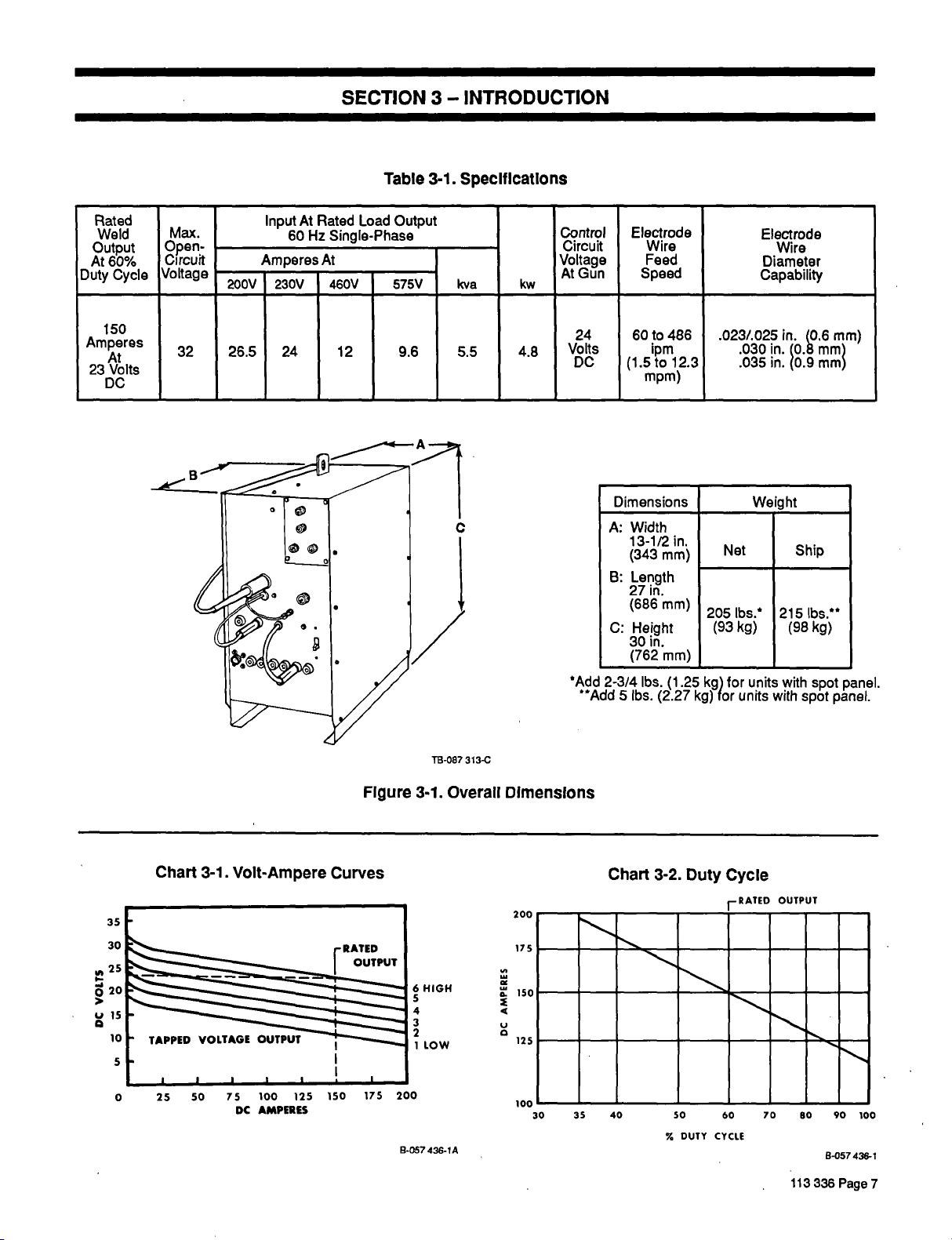
3-1.
SpecificatIons
Rated
Weld
Output
At
60%
Duty
Cycle
150
Amperes
At
Volts
23
DC
Max.
Open-
Circuit
Voltage
32
Rated
At
input
Hz
60
Single-Phase
At
200V 230V 460V
26.5
24
12
Load
Output
575V
9.6
kva
5.5
kw
4.8
Control
Circuit
Voltage
Gun
At
24
Volts
DC
*Add
2-3/4
~Add5lbs.
Electrode
Wire
Feed
Speed
60to486
1pm
to
(1.5
mpm)
Dimensions
Width
A:
13-1/2
(343
B:
Length
27
in.
(686
C:
Height
30
in.
(762
lbs.
12.3
in.
mm)
mm)
mm)
(1.25
(2.27
205
(93
kg)
kg)
.023/.025
.030
.035
Weight
Net
lbs.
kg)
for
units
units
for
Electrode
Wire
Diameter
Capability
in.
(0.6
10.~
in.
in.
215
with
with
mm~
mmj
~0.9
.
Ship
lbs.**
(98
kg)
spot
spot
mm)
TB-087
313-C
3-1.
6
5
4
3
2
1
Overall
HIGH
LOW
436-lA
Figure
Chart
3-1.
Volt-Ampere
In
.J
0
U
50
25
0
100
75
DC
AMPERES
125
Curves
150
175
200
9-057
Dimensions
Chart
200
-
175
150
@.
4
U
125
100
30
~
40
35
3-2.
%
~
50
DUTY
Duty
Cycle
1RATED
60
CYCLE
OUTPUT
-
--
~-
113
00
9-057436-1
336
90
Page
100
7
70
Page 16
3-1.
VOLT-AMPERE
The
volt-ampere
output
age
adjustment
age
SPEED
curves
With
determine
age.
3-2.
The
that
output
This
cycle
shown.
the
DUTY
duty
a
welding
without
welding
when
operated
but
it
must
utes
crease,
Refer
the
allow
to
to
output
cycles.
CAUTION:
a
INGS
curves
capabilities
is
control.
use
cycle
the
of
the
weld
CYCLE
is
power
Curves
the
overheating
power
operated
150
at
amperes
operate
proper
the
duty
cycle
the
Duty
of
the
welding
wIll
Do
not
exceed
CURVES
RATED
show
of
the
of
by
other
provided
volt-ampere
amperage
(Chart
percentage
source
source
at
no
cooling.
Cycle
EXCEEDING
damage
3-2)
can
and
is
150
at
for
load
If
increases.
chart
power
the
indicated
(Chart
OUTPUT
the
voltage
unit.
Voltage
the
FINE
setting
curves,
at
any
of
be
damaging
rated
amperes.
six
consecutive
for
the
the
welding
(Chart
source
DUTY
weldIng
duty
3-1)
and
and
TUNING/WIRE
fall
between
it
is
possible
minute
to
percent
unit
amperes
to
at
various
CYCLE
power
load
at
four
determine
particular
ten
a
operated
60
at
The
remaining
3-2)
cycles.
amper
amper
the
to
volt
period
a
given
the
unit.
duty
be
can
minutes,
min
de
duty
RAT
source.
3-3.
DESCRIPTION
This
unit
ing
power
signed
circuit
or
dc
Rated
Electrode
weld
cycle.
a
duty
Models
provide
on
time,
3-4.
SUPPLIED
The
following
power
source
sembly:
A.
B.
C.
D.
E.
The
welding
(2.7
mm)
valve,
gas
is
a
single-phase
source
for
Gas
transfer.itis
spray
output
with
the
the
controls
bumback
equipment
and
Running
bracket.
Wall
receptacle
Work
cable,
MWG-200
two
contact
Drive
rolls
and
0.8,
power
cord
power
and
facilities
constant
wire
and
Metal
feedersystem.
Arc
Welding
designed
Positive/Reverse
is
150
amperes,
optional
EQUIPMENT
gear
SPOT
for
regulating
and
time,
is
requires
with
pulse
supplied
customer
(200/230
work
clamp,
with
gun
tubes
for
0.9
source
(with
5/8
for
.023/.025,
hard
mm)
is
factory
plug
for
a
Spool
PULSE
spot
off
(Figure
gas
volt
and
inch
each
.030,
wire.
200/230
on
voltage
dc
This
(GMAW)
primarily
Polarity
volts
23
WELD
weld
time.
3-2)
with
the
installation
cylinder
models
jack
plug.
and
nozzle
size.
.035
(16mm)
wire
equipped
volt
gun.
weld
arc
unit
is
de
with
short
for
use
as
machine.
60%
at
dc,
PANEL
time/pulse
welding
or
as
rack
and
only).
and
in.
(0.6,
with
ft.
9
models),
113336
Page
Spreader
Bar
Wall
Receptacle
Figure
8
3-2.
Supplied
Equipment
Bracket
Page 17
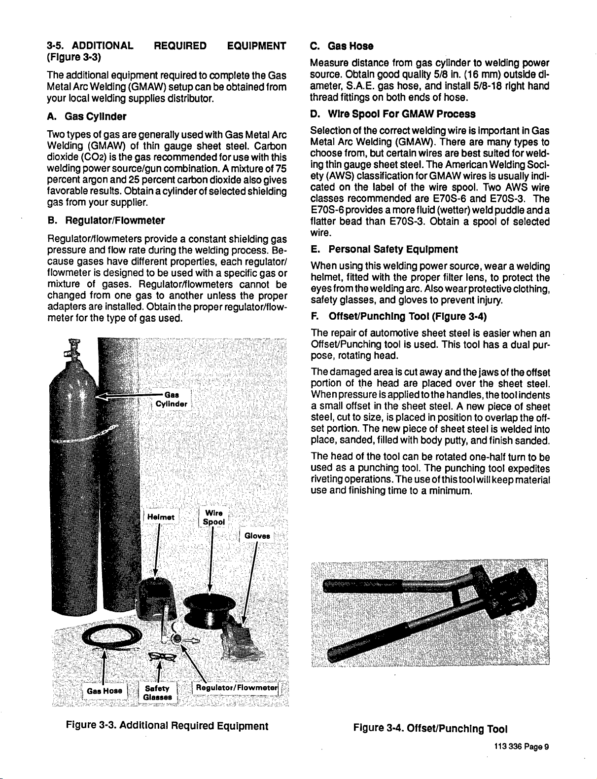
3-5.
ADDITIONAL
(Figure
The
Metal
your
A.
Two
Welding
dioxide
welding
percent
favorable
gas
B.
Regulator/f
pressure
cause
flowmeter
mixture
changed
adapters
meter
3-3)
additional
Arc
local
Gas
types
equipment
Welding
welding
CylInder
of
are
gas
(GMAW)
(GMAW)
is
source/gun
and
results.
supplier.
the
Obtain
from
(C02)
power
argon
your
Regulator/Flowmeter
lowmeters
and
flow
gases
for
have
is
designed
of
gases.
from
installed.
are
the
type
one
REQUIRED
requiredtocomplete
be
can
setup
supplies
of thin
gas
25
rate
different
distributor.
generally
gauge
recommended
combination.
a
cylinder
during
carbon
a
the
percent
provide
properties,
be
used
to
used
sheet
of
constant
welding
with
with
for
A
dioxide
selected
each
a
specific
Regulator/flowmeters
to
of
gas
gas
Obtain
used.
Gas
Cylinder
another
the
unless
proper
EQUIPMENT
the
Gas
Metal
Carbon
with
also
from
Arc
this
gives
obtained
Gas
steel.
use
mixtureof75
shielding
shielding
process.
gas
Be
regulator/
or
gas
cannot
the
be
proper
regulator/flow-
C.
Measure
source.
ameter,
thread
D.
Selection
Metal
choose
ing
ety
cated
classes
E7OS-6
flatter
wire.
E.
When
helmet,
eyes
safety
F.
The
Offset/Punching
pose,
The
portion
When
small
a
steel,
set
place,
The
used
riveting
use
Hose
Gas
distance
Obtain
S.A.E.
fittings
Wire
Arc
from,
thin
gauge
(AWS)
on
provides
bead
Personal
using
fitted
from
glasses,
good
gas
both
on
the
For
correct
Spool
of
Welding
but
certain
sheet
classification
the
label
recommended
a
than
Safety
this
welding
with
the
welding
and
OffseVPunchlng
of
repair
rotating
damaged
pressure
cut
portion.
sanded,
head
as
and
automotive
toolisused.
head.
area
of
the
head
is
applied
in
offset
to
a
the
is
size,
The
new
filled
of
the
tool
punching
operations.
finishing
time
from
gas
quality
hose,
endsofhose.
GMAW
welding
(GMAW).
wires
steel.
for
of
the
are
fluid
more
E7OS-3.
Equipment
power
the
proper
arc.
gloves
Tool
is
cut
away
are
to
sheet
placed
piece
with
body
can
tool.
The
use
to
cylindertowelding
in.
5/8
and
The
GMAW
wire
E7OS-6
Obtain
Also
to
(Figure
sheet
placed
the
steel.
in
of
be
The
of
minimum.
a
(16
install
Process
wire
is
There
are
best
are
American
wires
spool.
and
a
source,
filter
wear
weld
lens,
protective
(wetter)
prevent
3-4)
steel
This
tool
and
the
over
handles,
A
new
position
sheet
steel
and
putty,
rotated
one-half
punching
this
toolwill
mm)
5/8-18
important
many
suited
Two
spool
wear
injury.
is
easier
has
jaws
the
the
piece
to
overlap
tool
outside
rIght
In
types
for
Welding
is
usually
AWS
E7OS-3.
puddle
of
selected
a
welding
to
protect
clothing,
when
dual
a
of
the
sheet
tool
indents
of
the
is
welded
finish
sanded.
turn
expedites
material
keep
power
di
hand
Gas
weld
Soci
indi
wire
The
and
the
pur
offset
steel.
sheet
off
into
to
to
a
an
be
Gas
Figure
Hose
3-3.
Helmet
1/~
Safety
Glasses
Additional
Wire
Spool
Regulator!
:
Required
Gloves
Equipment
Figure
3-4.
Offset/Punching
Tool
113
336
Page
9
Page 18
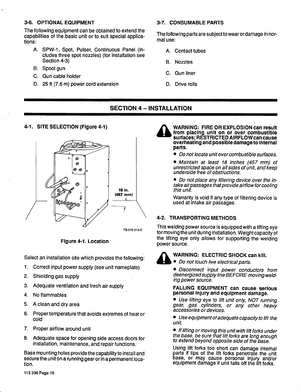
3-6.
OPTIONAL
The
following
capabilities
tions:
A.
B.
C.
D.
of
SPW-1,
cludes
Section
Spoolgun
Gun
cable
25
ft
(7.6
EQUIPMENT
equipment
the
basic
Spot,
three
spot
4-3)
holder
m)
power
be
can
unit
or
Pulser,
nozzles)
cord
obtained
to
suit
special
Continuous
installation
(for
extension
to
extend
applica
Panel
the
(in
see
3-7.
The
following
mal
use:
A.
B.
C.
D.
CONSUMABLE
parts
Contact
Nozzles
Gun
liner
Drive
rolls
are
tubes
PARTS
subject
to
wear
ordamage
in
nor
4-1.
SITE
SELECTION
Figure
(Figure
4-1.
LocatIon
4-1)
SECTION
18
in.
mm)
(457
TB-072
4-INSTALLATION
4A
4-2.
513-C
This
for
the
power
WARNING:
from
surfaces;
overheating
parts.
Do
Maintain
unrestricted
underside
Do
take
this
Warranty
used
TRANSPORTING
welding
moving
the
lifting
eye
source.
FIRE
placing
unit
RESTRICTED
and
locate
not
least
at
space
freeofobstructions.
not
place
air
passages
unit.
is
void
intake
at
power
unit
only
air
source
during
allows
OR
EXPLOSION
on
or
AIRFLOWcan
possible
unit
any
that
if
passages.
METHODS
installation.
combustible
over
inches
18
all
sides
on
filtering
provide
type
any
is
equipped
for
supporting
combustible
over
damage
(457
of
unit,
device
airflow
of
filtering
with
Weight
result
can
cause
to
Internal
surfaces.
mm)
and
keep
the
over
for
cooling
device
a
lifting
capacity
the
welding
of
in
is
eye
of
Select
1.
2.
3.
4.
5.
6.
7.
8.
an
Correct
Shielding
Adequate
No
flammables
A
clean
Proper
cold
Proper
Adequate
installation,
Base
mounting
336
the
Page
secure
tion.
113
installation
input
power
supply
gas
ventilation
and
dry
temperature
airflow
around
space
maintenance,
holes
unit
on
a
running
10
site
which
supply
and
area
that
unit
for
opening
provide
provides
(see
fresh
avoids
and
the
capability
orina
gear
unit
air
extremes
side
repair
the
following:
nameplate)
supply
of
access
permanent
doors
functions.
to
install
heat
loca
for
and
WARNING:
4~
Do
Disconnect
not
deenergized
ing
power
FALLING
personal
Use
gear,
or
accessories
Use
unit
If
lifting
the
base,
to
extend
Using
if
parts
base,
equipment
ELECTRIC
touch
live
input
supply
source.
EQUIPMENT
injury
lifting
gas
and
to
eye
cylinders,
or
devices.
equipmentof
or
moving
lift
tips
or
be
beyond
forks
may
sure
of
that
opposite
too
the
cause
damage
SHOCK
electrical
power
line
BEFORE
can
equipment
lift
unit
or
adequate
this
unit
lift
forks
side
short
can
lift
forks
personal
if
unit
falls
can
parts.
conductors
moving
cause
damage.
NOT
only,
other
any
capacity
with
lift
forks
are
long
of
the
damage
penetrate
injury
off
the
kill.
from
weld
serIous
running
heavy
lift
to
under
enough
base.
internal
the
and/or
lift
forks.
the
unit
Page 19

4-3.
a
1.
2.
3.
4.
RUNNING
UNCONTROLLED
unit
ment
Use
unit.
If
using
forks
lift
posite
Do
while
unit
Place
running
Install
the
bar
onto
of
each
of
or
base
the
rear
axle
wheel.
legs
by
source
hardware.
Block
tion
Slide
on
side
Secure
both
tion
GEAR
result
can
damage.
equipment
lift
are
long
sideofthe
not
place
it
is
blocks
gear.
4
two
front
the
as
unit
up
wheel/gas
through
axle
end
of
wheels
of
cotter
bending
INSTALLATION
TILTING
In
personal
of
adequate
to
handle
forks
enough
base.
part
any
suspended.
underf
in.
(102
corners
shown
rame
mm)
in
securely
cylinder
cylinder
with
a
place
around
pin
one
with
leg
in
this
extend
to
of
the
of
unit
casters
of
the
Figure
in
middle
rack
rack,
in.
3/4
cotter
the
clockwise
(FIgure
TIPPING
OR
Injury
capacity
unit,
out
body
before
and
welding
4-2
using
to
ease
assembly.
and
install
washer
flat
pins
axle
and
4-2)
or
equip
lift
to
be
sure
the
of
under
installing
spreader
power
3/8
installa
wheel
a
each
on
bending
by
in
direc
one
other
the
of
the
the
op
the
in.
leg
tour
Install
5.
using
hardware
Remove
6.
power
gear
screws
7.
Install
power
3/4
Install
8.
4-4.
OPTIONAL
(Figure
a
counterclockwise
of
axle
as
tightly
rack
x
Figure
front
two
wrapper
onto
bracket
as
and
chain
SPW-1
onto
3/4
wrapper
in
shown
onto
cylinder
5/16-18
(see
the
source
handle
as
cylinder
source
screws
cap
safety
shown
4-3)
touch
not
input
ELECTRIC
welding
power
before
WARNING:
Do
Shutdown
nect
procedures
Lockout/tagging
input
power
line
disconnect
fuses
ing
tagging
device.
plug
from
circuit
switch
fuse
breaker
should
(legs
as
possible).
welding
screws
cap
conform
power
and
to
source
associated
4-2).
of
discard.
1/4-20
using
4-2.
rear
4-2
holes
bracket.
SHOCK
in
panel
in
top
Install
x
of
using
rear
panel.
welding
running
3/4
welding
1/4-20x
INSTALLATION
kill.
can
parts.
discon
and
lockout/tagging
screws
cap
and
Figure
onto
in
Figure
existing
cylinder
PANEL
electrical
live
powersource,
employing
inspectingorinstalling.
procedures
from
receptacle,
in
open
or
box,
shutting
other
or
consist
of
removing
padlocking
position,
off
and
disconnecting
con
base
cap
remov
red-
Running
Nut
Washer
Spreader
Bar
Two
Casters
Figure
Cylinder
Front
4-2.
Bracket
Cotter
Running
____4..~
~
_v__
~
~
Pin
Screw
Cap
Gear
Installation
Flat
Cap
Safety
Washers
Wheel
Screw
Chain
Flat
Washers
Cotter
TC-049
Pin
808-C
113
336
Page
11
Page 20

IMPORTANT:
capabilities
moved
tions,
tor
facing
1.
Remove
corner
2.
Locate
move
pull
opening
mately
3.
Disconnect
4.
Connect
PLG2.
(see
5.
Install
panel,
for
during
suchasleft
the
module
front
of
wiring
wiring
of
end
in
in.
2
receptacle
Be
Figure
SPW-1
and
SPW-1
the
Spool
this
procedure
or
right,
front
panel.
panel.
harness
harness
wiring
front
panel
(51
mm).
jumpered
the
sure
4-3).
panel
secure
Spot
gun.
are
cover
from
harness
-
connector
RC55
connectors
into
using
will
Panel
Retain
reinstallation.
for
with
respect
from
plate
clamped
first
clamp
with
connectors
will
it
come
from
are
right
upper
screws
removed
not
all
upper
air
to
though
form
SPW-1
locked
corner
provide
hardware
All
direc
the
to
opera
right-hand
baffle.
and
carefully
through
approxi
PLG2.
plug
panel
together
of
in
Step
spot
re
Re
to
front
1.
WARNING:
a
rupture
loss
serious
er
causing
of
life;
Injury
Keep
cylinders
electrical
Never
allow
cylinder.
Always
bracket,
gear
B.
Reguiator/Fiowmeter
(Figure
1.
With
cap
der
flows
rid
of
around
4-4)
the
cylinder
(see
valve,
from
any
the
Figure
and
cylinder,
dust
valve
PRESSURIZED
serious
FALLING
and
away
circuits.
a
welding
fasten
a
wall,
cylinder
correctly
Stand
4-4).
the
open
close
dirt
or
seat.
personal
CYLINDERS
equipment
from
electrode
other
or
(Customer
installed,
to
valve
valve.
that
may
CYLINDERS
damage.
welding
any
to
securely
stationary
remove
sideofthe
one
slightly.
This
procedure
have
accumulated
can
and
injury
can
cause
oroth
touch
any
to
running
support.
Supplied)
cylinder
cylin
When
gas
gets
Plug
PLG2
Receptacle
RC55
SPw-1
Panel
Spot
4-5.
SHIELDING
A.
Gas
Secure
on
cylinder
chain
cylinder
the
vent
valve.
113336
Page
~
FIgure
Cylinder
gas
cylinder
bracket.
to
cylinder
12
4-3.
SPW-1
GAS
(Customer
to
If
the
wall
or
from
Panel
INSTALLATION
Supplied)
running
other
falling
gear
running
stationary
over
Installation
(Figure
using
is
and
not
support
breaking
gear
safety
be
to
to
off
3-3)
chain
used,
pre
the
Gas
Connection
(5/8-18
Fitting
Gas
Connection
(5/8-18
Fitting
Figure
Hose
Male
Required)
Hose
Male
Required)
4-4.
Installation
co2
Typical
Installation
-
TB-lOg
Regulator/Flowmeter
492
Page 21

2.
The
with
either
IMPORTANT:
leaks.
Do
-
Install
3.
the
tical
cylinder.
A
4.
shielding
of
the
tions.
fitting.
lator/flowmeter.
WORK
4-6.
A
10
ft.
supplied
onto
plug
A.
Work
1.
Insert
it
on
2.
Lay
clamp
3.
Align
the
terminal
and
4.
Bend
around
5.
Slide
the
regulator/f
a
stem,
C02
not
gas
face
position,
welding
Attach
Attach
(3
m)
with
the
Clamp
the
through
the
which
the
holeinthe
bolt.
the
the
work
lowmeter
nut
cylinders
A
gasket
lubricants
use
regulator
of
the
regulator/f
and
gas
power
one
other
CABLE
cable
the
unit.Toinstall
cable,
Installation
end
of
one
work
cable
has
smaller
to
lug
tabsonthe
the
work
insulating
clamp
must
connectors,
or
Argon/C02
should
or
onto
tighten
output
fittingisprovided
source
endofthe
endofthe
ASSEMBLY
with
a
lug
proceed
the
work
of
two
supplied
inside
the
flattest
holeinthe
work
cable
the
work
clamp
end
cable.
sleeve
handle.
be
and
be
installed
sealing
cylinder
gas
lowmeter
stem
nut
for
making
gas
gas
attached
the
work
follows:
as
(Figure
cable
with
the
handleofthe
inner surface.
work
terminal
with
of
the
the
on
properly
gasket
equipped
for
use
cylinders.
to
prevent
agents.
valve;
in
to
gas
one
at
the
onto
the
connec
and
gauge
securely
hosetothis
hosetothe
clamp
4-5)
terminal
the
handle
Secure
lug.
supplied
clamp
cable
sleeves.
insulating
clamp
the
work
work
with
keep
ver
gas
rear
output
regu
end
is
jack
lug
work
with
the
nut
handle
over
B.
Jack
Plug
The
supplied
cablestothe
weld
Remove
of
each
Clamp
cables
onto
1.
2.
tending
(44mm).
Place
3.
steel
mately
4.
Makeahalf
of
tie
wire
5.
Inserta3/8
looped
Twist
6.
7.
8.
9.
10.
11
12.
tie
around
tight
Cut
off
Bend
the
of
uninsulated
the
Wrap
lated
portion
Push
the
Insert
the
in
holes
Remove
sulating
and
plug
with
remaining
13.
Insert
the
insulating
installation
jack
plugs
weld
output
follows:
as
in.
3/4
weld
cable
upward
1/4
cable.
in
tie
in.
turn
(19
a
out
wire
(6
around
mm)
mm)
vise with
of
together.
in.
(9.5
endsoftie
wire
looped
twisted
wire.
until
(B)
insulationofcable.
endsoftie
tie
wire
portion
of
strip
jack plug
1/4-20
jack
cable.from
sleeve.
cable
8-32
sleeve
copper
of
cable
onto
setscrews
and
plug,
vise,
Slide
until
hole
hole
self-tapping
into
(Figure
used
are
4-6)
to
connect
receptacles.
insulation
of
the
uninsulated
vise
approximately
A,
(item
from
mm)
entire
of
and
Figure
endofinsulation.
cable
bringing
diameter
tie
wireistwisted
wire.
and
over
cable.
foil
twisted
cable
tighten
and
along
tightly
over
into
center
(E).
insert
insulating
in
insulating
in
jack
plug
(F);
screw
(F)
plug,
and
jack
Install
from
4-6)
looped
rod
the
around
tie
wire
copper
and
jack
plug
sleeve
sleeve
through
tighten.
weld
the
jack
plugs
one
end
1-3/4
approxi
ends
through
and
side
uninsu
(D).
foil
bottom
into
over
lines
hole
end
ex
in.
is
(C)
(E).
in
jack
up
in
6.
Slide
work
6
Step
Figure
the
clamp
4-5.
Work
remaining
handle.
Clamp
insulating
Installation
sleeve
Step
1
Ref.
over
&5
TB-025
the
190-IA
other
AU
B~
Ecj~--1
F?
FIgure
4-6.
~
Jack
U
~L
Plug
Installation
113
336
~1
S-0023
Page
13
Page 22

4-7.
WELD
POLARITY
4-8.
MWG-200.WELDING
GUN
CONNECTIONS
POSITIVE
WARNING:
ING
a
can
nections.
Do
Shutdown
ing
any
Do
welding.
Secure
before
IMPORTANT:
secure
1.
2.
IMPORTANT:
them
Connect
TIVE
Connect
weld
()
jack
(+)
output
Connections,
receptacles;
electrode
+
ELECTRIC
skIn
burn
touch
not
twist
not
welding.
Rotate
in
receptacles.
weld
jack plug
For
reverse
five
welding
lock
change
twistlock
jack
on
plug
output
from
receptacle.
Electrode
cable
becomes
NEGATIVE
SHOCK
or
damage
electrical
powersource
connections.
plug
position
plug
plugs
weld
cable
of
twistlock
in
selected
1/4
from
parts.
turn
receptacle.
work
cable
NegatWe/Straight
connections
negative.
can
kill;
electrical
before
plug
receptacle
clockwise
unit
into
NEGATIVE
into
to
weld
ARC
con
mak
while
to
POSI
Polarity
output
WARNING:
4~
nect
procedures
Lockout/tagging
input
line
ing
tagging
device.
A.
Gun/Feeder
And
Figure
IMPORTANT:
assembly.
gun
1.
Open
2.
Loosen
(Figure
IMPORTANT:
the
of
tip
ble
without
Insert
3.
let
guide,
power
as
bly
4.
lighten
5.
Close
Do
not
Shutdown
input
power
disconnect
fuses
circuit
4-8)
The
access
the
4-7).
Wire
the
guide
touching.
the
gun/feeder
through
source
illustrated
the
gun/feeder
and
secure
ELECTRIC
touch
live
electrical
welding
power
before
powersource,
employing
inspectingorinstalling.
procedures
from
plug
switch
from
fuse
box,
breaker
Connector
outlet
guideisprovided
door.
gun/feeder
guides
isasclosetothe
front
in
connector
should
connector,
the
access
panel
Figure
connector
access
and
SHOCK
parts.
lockout/tagging
consist
receptacle,
in
or
InstallatIon
open
or
shutting
other
position,
securing
be
installed
drive
which
hole
in
into
the
4-7
and
Figure
securing
door.,
kill.
can
and
discon
of
removing
padlocking
remov
off
and
red-
disconnecting
of
part
knob
so
as
possi
welding
assem
4-8.
knob.
4-7
the
that
out
(FIgure
as
rolls
includes
the
drive
113336
Hex
Page
Nut~
14
FIgure
Hub
Retainer
Ring
4-7.
Gun/Feeder
Wire
Connector
Outlet
Guide
And
Securing
Wire
Knob
Spool
Roll
Drive
Cover
Installation
Front
Panel
Of
Unit
Gun/Feeder
Connector
TA-072
573
Page 23

A
B
C
B.
Gun
GUN
The
GUN
switch
switch
GER
collar
welding
gas
4-9.
SPOOL
a
control
connector
receptacle,
fully
power
flows,
INSTALLATION
GUN
WARNING:
SPARKS
source
nect
cedures
how
Lockout/tagging
input
line
ing
tagging
device.
If
two
guns
both
electrode
operated.
Switch
TRIGGER
TRIGGER
connections.
clockwise.
source
and
wire
Do
not
Do
not
at
Shut
down
input
Watch
Keep
to
use
power
disconnect
fuses
circuit
are
connected
wires
Connection
(Figure
receptacleisprovided
Align
with
the
insert
feeds.
can
touch
connect
the
power
before
for
fire
a
it.
keyway
connector,
When
the
contactor
OF
OPTIONAL
ELECTRIC
cause
same
welding
live
electrical
two
time.
fire.
guns
power
employing
inspecting
fire.
extinguisher
gun
SHOCK
procedures
from
from
plug
fuse
will
switch
breaker
be
receptacle,
in
open
or
box,
or
to
this
welding
energized
Figure
4-8.
4-8)
for
the
on
and
switch
keys
the
rotate
on
GUN
is
closed
energizes,
can
parts.
to
this
welding
source
locko
or
nearby,
consist
and
ut/tagging
installing.
and
of
padlocking
position,
shutting
other
off
disconnecting
power
when
eithergun
WeldIng
making
the
gun
TRIG
threaded
the
shielding
ARC
kill,
power
discon
pro
know
removing
remov
and
red-
source,
is
Gun
Connections
A.
Shieiding
IMPORTANT:
wire
num
Connect
the
gas
The
connector
B.
Weld
insert
Spool
weld
output
tacle
key.
C.
SPOOL
(Figure
A
3-socket
making
and
the
sert
gun
clockwise.
fully
energizes,
Figure
Gas
Connections
Use
pure
welding.
the
shielding
regulator/f
Cable
Iowmeter
has
5/8-18
Connections
Gun
welding
receptacle
Rotate
plug
GUN
4-9)
SPOOL
connections
Spool
plug
GUN
Gun.
To
into
receptacle,
When
shielding
4-9.
Front
View
Receptacle
argon
hose
gas
right
with
clockwise
Receptacle
O
~
receptacle
between
connect
switch
gun
flows,
gas
Of
With
Socket
shielding
from
the
on
hand
cable
flat
side
1/4
WIRE
FEED
the
welding
the
and
is
and
3-Socket
gas
the
Spool
shielding
threads.
into
plug
facing
turn.
Connection
RC3
is
power
align
gun,
rotate
threaded
wire
the
feeds.
SPOOL
closed,
LocatIons
for
alumi
Gun
supply.
gas
POSITIVE
the
recep
provided
source
keyway,
collar
contactor
S-0037
GUN
to
for
in
113
336
Page
15
Page 24

The
socketsonthe
nated
as
Socket
Socket
+24
Socket
4-10.
A:
B:
volts
C:
WELDING
(Figure
WARNING:
4A
procedures
Lockout/tagging
input
line
ing
tagging
device.
1.
Open
2.
Remove
3.
Slide
bottom
4.
Rotate
Slide
flange
5.
Compression
mm)
pression
6.
Close
4-11.
HUB
WARNING:
4A
nect
procedures
Lockout/tagging
input
line
ing
tagging
device.
follows:
+24
Welding
closes
+24
4-7)
Do
Shutdown
nect
disconnect
fuses
left
spool
of
spool
spool
of
spools.
and
TENSION
Do
Shutdown
disconnect
fuses
SPOOL
volts
ac,
power
contactor;
volts
ac,
WIRE
ELECTRIC
touch
not
welding
input
power
before
power
side
retaining
plug
from
circuit
access
wire
of
fuse
ring.
spool.
until
hole
onto
hub
hub.
spring
For
8
secure
not
Reinstall
access
ADJUSTMENT
ELECTRIC
touch
spring.
welding
input
power
before
power
plug
from
circuit
fuse
GUN
Hz.
60
source
volts
0
Hz.
60
SPOOL
live
electrical
powersource,
employing
inspecting
procedures
from
receptacle,
onto
is
in.
box,
door.
hub
in
spool
until
not
(203
in
open
or
or
it
required
mm)
switch
breaker
retaining
door.
live
electrical
wersource,
po
employing
inspecting
procedures
from
receptacle,
box,
in
open
or
or
switch
breaker
receptacle
contactor
opens
SHOCK
contactor.
INSTALLATION
can
parts.
lockout/tagging
or
installing.
consist
position,
shutting
other
disconnecting
wire
that
so
with
aligns
seats
against
for
spools,
ring
(Figure
SHOCK
can
parts.
lockout/tagging
or
installing.
consist
position,
shutting
other
disconnecting
are
desig
control;
kill.
discon
and
of
removing
padlocking
remov
off
12
onto
and
feeds
pin
use
in.
in
com
hub.
red-
off
hub.
back
(305
4-7)
kill.
anddiscon
of
removing
padlocking
remov
off
and
red-
backlash
vent
is
ment
of
4-12.
a
required,
the
spindle
ELECTRICAL
WARNING:
Shutdown
nect
procedures
Lockout/tagging
locking
removing
red-tagging
ing
A.
Electrical
Operate
60
one
data
tric
vice
and
B.
a
Jumper
from
bag
the
the
1.
2.
4A
the
ac
Hertz,
of
the
label
on
for
utility
available,
inspection
Jumper
WARNING:
tion
fore
links
different
attached
inputterminal
input
voltage
Remove
Compare
nal
board
voltage
put
CAUTION:
JUMPER
unit.
voltage
Store
terminals.
the
when
loosen
support
INPUT
ELECTRIC
Do
not
touch
welding
input
power
before
disconnect
line
fuses
circuit
device.
Requirements
Input
welding
power
electrical
the
information
supply.
unit
how
power
input
nameplate.
proper
required.
Link
Installation
Read
at
begInning
proceeding.
usedtoallow
are
line
voltages.
the
to
input
board
label.
the
wrapper.
position
the
to
voltage
label.
INCORRECT
LINK
Position
jumper
label
unused
wire
feeding
or
tighten
shaft
accordingly.
CONNECTIONS
INPUT
electrical
live
powersource,
employing
inspecting
procedures
switch
fuse
from
breakerorother
source
The
input
voltages
the
about
connections
(Figure
and
of
entire
the
The
jumper
terminal
forthe
highest
of
jumper
link
PLACEMENT
links
(see
Figure
jumper
ceases.
hex
the
SHOCK
nut
can
parts.
lockout/tagging
or
installing.
consist
in
open
or
box,
from
shutting
a
single-phase,
voltage
shown
Contact
type
the
of
electrical
should
4-10)
follow
safety
Section
equipment
links
board
or
voltage
linksonthe
arrangement
INPUT
can
shown
as
4-10).
links
across
ad
If
just
the
on
kill.
discon
and
of
pad
position,
off
disconnect
match
must
the
on
input
local
elec
be
made,
Informa
4-12
to
operate
be
may
installed
shown
termi
input
the
on
VOLTAGE
damage
the
on
input
linked
end
and
ser
be
in
a
on
on
in
Check
the
feed
tension
113336
the
hub
roll.
should
Page
The
be
16
tension
wire
sufficient
by
slowly
should
to
pulling
unwind
keep
freely,
the
wire
the
wire
but the
taut
toward
and
hub
pre
3.
4.
install
jumper
match
Reinstall
the
links
available
wrapper.
onto
input
the
line
terminal
input
voltage.
board
to
Page 25

Air
Baffle
Table
3-2.
Input
Conductor
And
Fuse
Size
Figure
C.
Wall
(Figure
a
4-10.
Input
Receptacle
4-11)
WARNING:
Do
not
Install
a
circuit
input
Connect
input
Read
unit.
source
power.
and
of
entire
line
disconnect
power
ning
The
convenient
electrical
whenever
the
Voltage
ELECTRIC
touch
fusible
to
input
follow
means
power
it
is
input
Board
And
Power
live
line
the
welding
conductors
before
safety
Section
from
necessary
Voltage
Input
iabel
Jumper
Link
Terminal
Jumper
Cable
SHOCK
electrical
disconnect
power
Ref.
Links
Connections
can
parts.
switch
source.
the
to
TD-072
507-F
Location
kill.
in
welding
the
connectingtosingle-phase
information
4-12
before
switch
to
provides
completely
the
welding
to
inspect
at
begin
proceeding.
safe
or
and
all
source
service
a
remove
power
Voltage
Input
Conductor
Input
Size_(AWG)
Ground
Conductor
Size_(AWG)
Size
Fuse
In
Amperes
*Conductorsize
specifications
conductors,
with
not
a
raceway
counted
of
more
size
input
NEC).
in
not
*Fuse
rated
630
is
for
having
than
(Article
as
a
is
based
amperage
200V
10
10
40
basedonNational
allowable
a
temperature
three
single
of
310
current-carrying
not
on
of
the
230V
10
10
35
ampacities
rating
current-carrying
NEC).
(The
conductor.)
than
more
welding
460V
Electrical
of
insulated
167F
of
ground
200
percent
source
power
575V
14 14
14 14
20
Code
(NEC)
copper
(75C),
conductors
conductor
of
(Article
15
is
the
All
models
cable.
Models
equipped
ceptacle.
convenient
the
wall
receptacle
allowing
top,
undue
volts
The
the
a
bending
Models
must
Use
electrical
having
have
black
line
be
connected
a
grounding
WARNING:
disconnect
ductor
to
Incorrect
trically
The
ing
purposes
are
equipped
requiring
with
a
three-prong
The
wall
the
power
or
an
white
not
to
not
input
receptacle
by
with
twisting.
electrical
power
to
method
authority.
connect
the
connect
ilne
location
prewired
and
inspection
Do
Do
an
input
energized
ground
power
conductor
source
only.
with
three-conductor
a
200
or
polarized
should
a
competent
the
grounding
cable
to
hang
input
cables
conductors
switch,
and
with
must
the
aproperground
that
is
acceptable
ELECTRIC
an
ground
the
terminal.
connections
welding
chassis
SHOCK
input
terminal.
ground
power
is
connected
230
volts
plug
be
installed
electrician.
terminalatthe
downward
voltage
three
be
connected
green
(see
can
or
(white
(green)
result
can
source
andisfor
power
are
input
and
wall
in
Install
without
above
230
conductors.
conductor
Figure
4-11).
the
local
to
kill.
con
black)
conductor
in
elec
an
chassis.
to
the
weld
grounding
re
a
4-11.
FIgure
WaIl
Receptacle
And
Power
A-fl2
Cable
075
Connections
WELDING
to
4-13.
a
WARNING:
nect
cedures
structed
The
ever
Lockout/tagging
input
line
ing
tagging
device.
WIRE
Shut
down
input
before
Do
not
energize
to
Do
not
touch
welding
the
gun
power
disconnect
fuses
from
circuit
THREADING
ELECTRIC
welding
power
do
wire
so.
employing
inspecting
live
is
SHOCK
power
or
welding
powersource
electrical
electrically
triggerisdepressed.
procedures
from
plug
switch
fuse
breaker
receptacle,
in
open
or
box,
or
shutting
other
(Figure
can
source
lockout
and
tagging
installing.
parts.
energized
Consist
of
removing
padlocking
position,
off
disconnecting
4-7)
kill.
discon
untilin
when
remov
and
pro
red
113
336
Page
17
Page 26

CAUTION:
a
1.
2.
IMPORTANT:
when
the
3.
4.
ture
skin.
do
other
when
Open
Install
loosened
wire
Unreel
of
wire
Cutoff
sharp
5.
Release
pivot
roll.
6.
Route
drive
Figure
7.
Pivot
wounds;
Do
not
so.
not
Do
personnel,
threading
Allow
left
side
welding
during
and
from
any
edges.
pressure
upper
welding
roll
groove,
4-7).
upper
WELDING
HOT.
activate
point
gun
welding
cool
tq
gun
access
wire
spool
Spooled
from
the
wire
the
threading
straighten
wire
spool.
wire
that
is
spring
drive
roll
wire
into
and
drive
roll
can
WIRE
SURFACES
trigger
gun
toward
or
any
before
door.
according
has
spool.
until
part
any
conductive
wire.
touching.
a
tendency
Maintain
to
operation.
approximately
and
on
and
drive
away
inlet
wire
onto
remove
roll
from
guide,
outlet
lower
bent,
up
wire
into
down
cause
Section
a
6
punc
burn
can
instructed
the
of
body,
surface
4-10.
unravel
to
firm
grip
in.
any
(152
burrs
mm)
assembly,
lower
drive
lower
along
guide
roll.
drive
to
on
or
and
(see
Reinstall
8.
in
is
groove
9.
Lay
gun
possible.
WARNING:
4~
The
ever
WELDING
ing.
other
when
10.
Energize
welding
spot
in
the
11.
Depress
approximately
wire
feeds
in.
1/4
12.
Deenergize
13.
Adjust
essary.
14.
Close
IMPORTANT:
wire
a
sharp
extends
ing
has
pressure
of
cable
Do
not
touch
welding
the
gun
Do
not
point
personnel,
threading
welding
capabilities,
CONTINUOUS
and
hold
more
welding
tension
hub
and
secure
For
1/4
end.
spring.
rolls.
drive
assembly
ELECTRIC
live
wire
is
trigger
WIRE
can
gun
or
wire.
powersou
position.
the
gun
in.
1/4
(6
than
1/4
power
according
access
smoother
a
in.
(6
Be
out
electrical
electrically
is
depressed.
cause
toward
any
place
trigger
mm)
in.
door.
weld
mm)
that
sure
as
straight
SHOCK
parts.
energized
puncture
part
any
conductive
If
rce.
powersource
Selector
the
until
the
out
out
nozzle,
source.
Section
to
start,
outofcontact
welding
and
kill.
can
wound
the
of
wire
the
nozzle.
gun
cutwire
4-11,
be
sure
tube
wire
flat
as
when
body,
surface
has
switch
feeds
off
if
nec
weld
and
If
to
5-1.
POWER
(Figure
Placing
the
whenever
indicates
the
welding
Placing
down
the
light.
IMPORTANT:
the
sition,
unless
run
The
fan
motor
erates
when
5-4).
113336
Page
5-1)
POWER
POWER
power
the
that
the
POWER
welding
pilot
the
additional
18
SWITCH
switch
source.
POWER
unit
the
When
light
internal
is
is
switchinthe
power
the
comes
thermostatically
AND
in
the
The
switch
isinthe
receiving
source
POWER
butfhefan
on,
components
cooling
SECTION
PILOT
ON
I
QOFF
ON
position
pilot
ON
input
OFF
and
turns
switch
are
controlled
is
required
5-OPERATOR
energizes
comes
light
position
power.
position
off
in
is
the
motordoes
already
and
(see
LIGHT
and
shuts
the
pilot
Onpo
warm.
only
Section
on
not
op
CONTROLS
THICKNESSNOLTS
5-2.
CAUTION:
a
and
plug
Arcing
pitted.
tor
The
THICKNESS/VOLTS
tacles
provide
to
the
secure
plug
from
receptaÆle.
higher
IMPORTANT:
NESS/VOLTS
rotate
it
receptacle
Do
not
change
position
causes
Eventually
no
plug
selection
a
numbered
After
receptacle,
in
place.
1/4
turn
SELECTOR
THICKNESS
VOLTS
ARCING
while
the
can
contact
THICKNESS/VOLTS
welding
contact
continuity
longer
workstoselect
selector
of
heat
receptacle,
installing
When
counterclockwise
selector
rotate
removing
damage
surfaces.
under
or
surfaces
is
lost
jack
input
the
hotter
plug
1/4
plug
plug
while
(FIgure
jack
load.
to
and
the
output
and
plug
to
weld.
the
the
into
clockwise
turn
from
receptacle,
wit
hdra
5-1)
plug
selector
become
selec
range.
recep
The
weld.
THICK
wing
Page 27

Spot
On
Negative
Output
Time/Pulse
Control
Time
Weid
(-)
Receptacle
Burnback
Control
Pulse
Control
Time
Fine
Tuning/Wire
Receptacle
Pilot
Time
Off
Control
Gun
Light
Trigger
And
Speed
Plug
FINE
5-3.
(FIgure
The
lectionofthe
weld.
clockwise
The
trol
tual
5-1)
FINE
Rotating
scale
calibrated
is
wire
feed
IMPORTANT:
trol
may
be
IMPORTANT:
WIRE
SPEED
when
using
FAN-ON-DEMAND
5-4.
fan
turn
when
SR3
not
cool
motor
on
are
run.
or
The
not
runs
bly
may
are
TUNING/WIRE
O
Q
TUNING/WIRE
at
speed
FINE
the
increases
around
wire
the
in
percent
FINE
speed.
The
FINE
adjusted
THICKNESS/VOLTS
with
main
warm.
The
when
while
PULSE
In
the
control
FAN
CONTROLLED
BY
THERMOSTAT
is
thermostatically
the
unit
transformerTiand/or
Under
fan
the
unit
FINE
TUNING
WIRE
SPEED
which
welding
TUNING/WIRE
feed
TUNING/WIRE
and
TUNING/WIRE
welding.
mode,
be
must
POWER
normal
motor
turns
POWER
SPEED
SPEED
control
speed.
does
not
at
set
taps
controlled
switch.
loading,
off
switch
Voltage
Adjustment
Receptacles
Selector
Figure
CONTROL
provides
feeds
wire
SPEED
SPEED
indicate
SPEED
FINE
the
50
percent
and
5
6.
The
rectifierassem
the
Ti
when
is
turned
And
Plug
5-1.
into
control
con
the
TUNING!
or
and
does
fan
motor
fan
motor
and
Operator
se
the
ac
con
less
SR3
off.
Controls
Normally-open
control
CR2
OPTIONAL
5-5.
(FIgure
IMPORTANT:
WIRE
Exceeding
breaker
cuit
feed.
A.
Selector
Selector
The
tinuous,
1.
Continuous
Placing
position
ing
closed.
2.
Spot
Placing
and
for
Pulse
3.
Placing
and
for
control.
stops
the
5-1)
SPEED
the
in
Switch
switch
or
spot,
the
and
wire
for
Position
the
depressing
the
length
Position
the
depressing
the
length
At
feeding
thermostats
fan
motor.
SPOT
PULSE
In
the
control
50
percent
motor
the
enables
must
pulsed
Position
Selector
depressing
as
long
Selector
the
of
time
Selector
the
of
time
the
end
of
for
TP1
PULSE
mode,
be
set
control
control
the
wire
feed
switchinthe
the
gun
the
as
switch
trigger
gun
set
the
on
switch
trigger
gun
set
on
the
pulse
the
length
and
TP2,
PANEL
FINE
the
50
at
percent
setting
operator
circuit
may
stopping
to
operation.
CONTINUOUS
trigger
trigger
gun
in
SPOT
the
feeds
SPOT
in
PULSE
the
feeds
the
PULSE
on
time,welding
time
of
113
TB-087
and
CONTROLS
TUNING!
or
the
(rip
select
feeds
remains
position
welding
TIME
control.
position
welding
ON
set
on
336
Page
313-C
relay
less.
cir
wire
con
weld
wire
wire
TIME
wire
the
19
Page 28

PULSE
to
ues
pulse
until
the
provides
thin
on
the
and
B.
The
operator
pulse
creases
brated
on
C.
The
select
Time/Pulse
Spot
SPOT
to
operation.
spot/pulse
in
percent
time.
Pulse
PULSE
from
Off
operation.
OFF
TIME
feed
trigger
gun
better
control
gauge
metals,
likelihood
TIME/PULSE
select
from
Rotating
and
Time
TIME
OFF
1
to
0.25
Rotating
control.
on
and
is
released.
the
of
The
off
thereby
of
melt-throughs.
On
Time
TIME
ON
4
0.5
time.
on
does
Control
second
the
to
the
The
not
control
control
seconds
indicate
of
welding
for
the
The
heat
input
decreasing
Control
control
of
control
control
actual
enables
off
pulse
clockwise
wire
contin
selected
option
pulse
the
to
distortion
enables
time
pulse
clockwise
scaleiscali
spot/pulse
the
operator
time
for
increases
times
weld
the
for
in
to
pulse
off
pulse
and
does
D.
Burnback
BURNBACK
The
justing
that
onds)
after
gized
By
adjusting
neither
of
the
gun.
crease
into
tate
and
burnback
brated
back
the
the
the
rotate
in
time.
time.
not
the
time
the
the
freeze
If
burnback
contact
control
the
time.
percent
control
The
indicate
Time
TIME
period
welding
wire
this
control
in
the
the
welding
tube,
clockwise
control
The
and
scaleiscalibrated
actual
pulse
Control
control
(up
wire
feeding
provides
maximum
to
a
remains
has
stopped.
properly,
weld
puddle
freezes
wire
time.Ifthe
decrease
counterclockwise
scale
does
welding
the
to
increase
surrounding
not
represent
time.
off
a
electrically
the
welding
the
in
nor
to
wire
burnback
burnback
the
to
the
an
in
means
of
0.25
wire
contact
the
work,
burns
time.
decrease
control
actual
percent
ad
of
sec
ener
will
tube
in
back
Ro
time,
the
cali
is
burn-
a
113
WARNING:
MOVING
IMPROPER
ENVIRONMENT
erating.
Warranty
operated
removed.
ARC
can
hearing.
FUMES
your
gases.
breathing
WELDING
wounds.
any
HOT
cause
how
dung.
336
Page
Do
not
all
Keep
with
RAYS,
burn
Wear
correct
AND
health.
Keep
your
Ventilate
If
ventilation
Do
not
point
conductive
METAL,
fire
Watch
Keep
Do
Allow
for
a
to
use
not
work
20
ELECTRIC
PARTS
AIRFLOW
can
touch
live
covers
is
void
if
any
SPARKS,
and
eyes
eye,
GASES
head
to
keep
is
device.
WIRE
gun
surface,
SPATTER,
and
burns.
fire.
fire
extinguisher
it.
use
near
and
equipment
SECTION
SHOCK
can
cause
AND
damage
electrical
and
panelsinplace
the
welding
of
AND
and
ear,
can
of
the
breathing
the
NOISE
portion
skin;
out
from
inadequate,
can
cause
rd
to
wa
any
other
or
AND
nearby,
flammable
to
6-
can
serious
EXPOSURE
internal
parts.
while
power
HOT
body
source
outer
enclosure
SURFACES
can
protection.
seriously
fumes.
fumes
use
approved
puncture
of
part
material.
coolbe
the
personnel.
SLAG
and
fore
SEQUENCE
kill;
injury;
TO
parts.
op
damage
harm
and
body,
can
know
han
is
OPERATION
OF
MAGNETIC
can
going
operations.
See
Arc
safety
6-1.
GAS
UOUS
ARC
4A
AND
(GMAW-P)
WARNING:
tion
proceeding.
1.
Install
IMPORTANT:
NEGATIVE
from
unit
ceptacle
2.
Thoroughly
CAUTION:
a
vehicle
components.
ing
ing
sible
and
affect
Wearers
near
Section
Welding
information.
METAL
GAS
at
beginning
and
connect
Be
weld
()
is
installed
Section
(see
clean
Disconnect
vehicle.
on
a
Disconnect
vehicle.
on
a
Place
work
to
avoid
Be
sure
tight.
FIELDS
pacemaker
should
arc
welding,
-
1
Safety
Power
ARC
WELDING
METAL
Read
unit
that
sure
output
into
POSITIVE
4-7).
joint
WELDING
computers
both
vehicle
clamp
long
all
weld
FROM
operation.
consult
gouging,
Rules
Source
ARC
WELDING-PULSED
and
follow
of
entire
according
work
cable
receptacle
of
area
battery
workpiece.
CURRENTcan
and
cables
computer(s)
close
as
electrical
circuit
connections
HIGH
CURRENTS
their
For
for
doctor
orspot
basic
before
welding
Operation
welding
(GMAW)-CONTIN
Section
is
installed
weld
and
weld
Informa
6
before
4.
cable
output
safety
Section
to
(4
damage
other
to
the
before
before
weld
electronIc
weld
weld
as
pos
paths.
clean
are
Of
into
re
Page 29

Wear
3.
welding
ANSI
4.
Prepare
Connect
a.
workpiece.
Select
b.
thread
ual.
Turn
5.
6.
Open
and
adjust
a.
Open
spring
drive
WARNING:
a
contact
The
with
ger
b.
gun
just
IMPORTANT:
typicaL
or
Welding
welding
shielding
c.
d.
e.
insulating
dry
helmet
Z49.1.
for
welding
and
as
on
shielding
roll
drive
gas
left
on
roll
Do
not
Do
not
withitwhile
welding
it
carry
is
depressed.
Energize
trigger
gloves
with
proper
as
work
clamp
obtain
instructed
at
gas
coverto
system
side
access
roll
drive
and
up
touch
touch
away
ELECTRIC
live
welding
and
wire
weld
current
welding
for
approximately
regulator/flowmeter
hose.
Shielding
out
in
a
drafty
gas.
Deenergize
Close
drive
Pivot
upper
and
roll,
Close
and
gas
of
position
environment
welding
roil
housing
drive
reinstall
secure
and
filter
follows:
to
clean,
proper
in
Section
the
source.
prevent
as
wire
follows:
door,
assembly,
from
SHOCK
electrical
wire
welding.
metal
all
whenever
flow
at
power
roll
pressure
side
access
source,
and
rate
high
as
down
power
according
bare
4-1301
feed,
and
pivot
drive
can
and
wire,
this
and
clothing,
lens
welding
release
lower
parts.
metal
or
any
in
parts
the
and
seconds
15
to
purge
to
of
15
wire
feed
will
require
source.
follows:
lower
onto
spring.
door.
wear
to
metal
and
Man-
purge
pressure
upper
roll.
kill.
part
contact
trig
gun
depress
ad
to
the
gas
25
cfh
speeds
more
drive
at
in
7.
8.
is
If
applicable,
SPW-1
tional
continuous
PULSE
9.
If
TIME
tings
Set
VOLTS
metal
tion
pulse
and
(see
a
thickness
5-2
welding,
voltage
selector
IMPORTANT:
appropriate
Be
base
bead
weld
metal,
10.
that
sure
metal
does
voltage.
decrease
Rotate
The
50.
along
not
the
welding.
11.
Energize
Be
12.
IMPORTANT:
the
accurately
helmet
13.
IMPORTANT:
ter
crackling
reached,
14.
sure
mm)
(6.4
lower
welding
trigger
gun
position
and
Readjust
necessary.
minimum
at
a
sounding
arc
If
pulse
TIME
and
place
Panel
welding,
position
if
PULSE
Section
condition
plug
and
Table
and
is
It
important
for
type
weld
the
the
penetrate
If
the
edges
weld
FINE
control
can
welding
welding
out
gun
helmet,
The
is
pressed;
pressing
FINE
Adjust
while
will
sound
welding,
PULSE
place
SPOT
control
switch
the
(see
TIME/PULSE
the
in
pulse
rotate
OFF
Selector
CONTINUOUS
the
and
welding
the
TIME
5-5).
with
the
is
that
appropriate
of
type
shielding
6-1).
selected
the
that
and
of
bead
total
weld
length
the
of
thickness
is
thoroughly
of
the
base
metal,
the
bead
voltage.
TUNING/WIRE
be
adjusted
power
wire
source.
extends
nozzle,
and
welding
wire
SPEED
approximately
position
depress
is
not
therefore,
weld
on
gun
trigger.
gun
TUNING/WIRE
wire
the
joint
SPEED
speedtokeep
maintainingasteady,
arc.
(When
like
readjust
OFF
optimum
frying
SPOT
TIME
bacon).
control
on
position
switch
Section
desired
to
THICKNESS/
the
for
(see
gas
voltage
of
material.
fused
If
bead.
increase
into
cut
as
the
control
required
over
gun
trigger.
gun
energized
the
operator
before
control
weld
arc
TIME/PULSE
as
necessary.
the
op
if
in
the
5-5).
ON
set
base
Sec
be
the
with
weld
the
the
base
to
while
in.
1/4
joint,
until
can
lowering
as
spat
quick-
length
is
ON
Voltage
Metal
Thickness
.030
.035
*Amperage
Table
6-1.
Adjustment
Receptacle
*Amperage
in.
(0.8
mm)
*Amperage
in.
(0.9
mm)
values
are
Suggested
Gauges
Inches
Millimeters
For
Wire
For
Wire
obtained
Parameters
by
adjusting
1
2218
.035+
.8+
3055
35-65
the
For
FINE
ContInuous
2
1816
.047+
1.2+
55-85
65-95
TUNING/WIRE
Gas
3
1614
.059+
1.5+
85~105
95-115
SPEED
Metal
Arc
Welding
4
1412
.067+ .104+
1.9+
105130
115-140
Control.
(GMAW)
1210
130150
140-180
5
2.6+
113
6
10
or
Heavier
.134+
3.4+
150180
175-220
336
Page
21
Page 30

6-2.
GAS
(Models
WARNING:
4A
tion
proceeding.
1.
Install
IMPORTANT:
NEGATIVE
from
unit
ceptacle
2.
Thoroughly
CAUTION:
a
vehicle
components.
ing
ing
sible
and
3.
Wear
welding
ANSI
4.
Prepare
Connect
a.
workpiece.
b.
Select
thread
ual.
5.
Turn
6.
Adjust
hose
gas
a.
Open
spring
drive
WARNING:
a
contact
Welding
carry
depressed.
b.
Energize
gun
just
gas
IMPORTANT:
typicaL
welding
ing
113
gas.
336
Welding
in
Page
METAL
With
Optional
at
beginning
and
connect
Be
weld
()
is
installed
Section
(see
clean
computers
Disconnect
vehicle.
on
a
Disconnect
on
vehicle.
a
Place
work
avoid
to
Be
sure
tight.
dry
insulating
helmet
Z49.1.
for
welding
and
as
on
shielding
shielding
follows:
as
left
on
roll
up
Do
not
touch
Do
touch
not
withitwhile
wire
weld
trigger
the
regulator/f
hose.
Shielding
outof
a
drafty
22
ARC
WELDING
Read
sure
output
into
SPW-1
unit
the
POSITIVE
Panel
and
follow
of
entire
according
work
cable
receptacle
4-7~.
joint
WELDING
both
battery
vehicle
clamp
electrical
long
weld
all
circuit
gloves
with
proper
follows:
as
work
clamp
obtain
instructedinSection
at
gas
pressure,
gas
side
access
roil
drive
and
away
ELECTRIC
live
welding
workpiece.
CURRENT
and
cables
computer(s)
close
as
connections
and
filter
to
clean,
proper
the
source.
and
door,
assembly,
from
SHOCK
electrical
wire
of
area
welding.
and
all
metal
current
welding
for
whenever
power
approximately
gas
position
environment
parts
source,
lowmeter
flow
rate
at
high
will
require
(GMAW)-SPOT
Only)
safety
Section
Section
to
is
installed
and
weld
weld
(-,-)
other
to
can
before
before
the
output
electronic
weld
paths.
are
clothing,
lens
welding
4-13
release
lower
parts.
or
any
the
15
and
of
wire
and
according
bare
wire,
of
this
purge
and
pivot
drive
can
metal
in
contact
trigger
gun
and
seconds
to
purge
15
to
feedspeedor
more
informa
6
before
6.
into
cable
re
damage
weld
weld
as
pos
clean
wear
to
metal
at
and
man-
shielding
pressure
upper
roll.
kill.
in
part
with
it
is
depress
to
ad
the
25
cfh
is
shield
c.
Deenergize
Close
d.
Pivot
roll,
Close
e.
7.
Set
spot
speed,
Obtain
a.
but
nal
b.
Place
in
CONTINUOUS
age
to
Steps
and
ple
After
c.
have
source,
gun,
welding
d.
Obtain
ness
Place
e.
and
BURNBACK
IMPORTANT:
wire
burn
to
wire
increase
into
wire
freezes
the
burns
to
replace
Manual
ing
cycle,
back
the
essary
Owners
dure.)
f.
Make
weld
Table
To
spot
piece,
trigger.
and
seton
trol.
IMPORTANT:
the
gun
trigger
accurately
helmet
IMPORTANT:
the
SPOT
and
TIME/PULSE
completing
before
resets
8.
the
for
After
cycle
another
all
workpiece.
welding
drive
roll
housing
drive
upper
and
reinstall
and
secure
weld
parameters
weld
spot
sample
time)
pieces
approximately
workpiece.
Selector
and
wire
wire
9
feed
feed
thru
Switch
13
speed
metal.)
voltage
been
and
of
welding
rotate
back
contact
back
several
parameters
6-2
hold
shielding
the
position
pressing
The
the
spot
weld
and
set,
remove
replace
nozzle.
sample
final
workpiece.
SPOT
TIME
The
correct
free
just
to
the
burnback
workpiece
tube,
into
the
contact
for
contact
practice
check
to
weld,
place
gun
When
trigger
gas
SPOT
The
welding
is
pressed;
gun
gun
gun
weld
is
complete,
weld
parameters
continuouswelding
metal
power
of
the
motionless,
TIME/PULSE
on
trigger.
trigger
ON
cycle,
cycle.
source.
power
follows:
as
roll
down
pressure
side
access
(weld
follows:
as
of
metal
twice
the
on
optional
parameters
Section
for
metal
feed
and
position,
speed
in
wire
deenergize
nozzle
TIME/PULSE
time.
will
with
of
the
same
source
controls
burnback
the
decrease
contact
are
sample
gun
is
wire
to
weld
at
the
lithe
tube,
in
tube
tube
replacement
welds
spot
set
correctly.
weld.)
nozzle
depressed,
feed
for
is
not
therefore,
weld
joint
be
must
TIME
control
lithe
the
cycle
have
been
lower
onto
spring.
door.
the
SPW-1
set
welding
wire
same
voltage,
thickness
according
6-1.
(Set
thickness
speed
parameters
welding
nozzle
appropriate
and
type
in
SPOT
ON
TIME
desired
time
puddle.
welding
burnback
the
end
of
it
may
gun.
to
determine
settings.
allows
lithe
wire
(See
(Refer
directly
and
on
depress
welding
the
length
ON
TIME
energized
the
operator
before
held
trigger
stops,
closed
has
is
and
set,
lowering
timed
released
weld
drive
feed
type,
fi
of
the
panel
volt
voltage
of
sam
power
from
spot
thick
mode,
and
the
weld
the
weld
burns
time.
be
nec
gun
proce
to
work-
gun
wire
of
time
Con
until
can
until
out,
the
unit
final
If
if
Page 31

Table
6-2.
Checking
Weld
Parameters
Weld
Appearance
Dark
blue
circle
protrusion
reverse
Small
reverse
Excessive
on
reverse
No
dark
small
reverse
when
pulled
is
torn
of
metal.
No
dark
small
reverse
when
pulled
minimal
lower
visible
side
burn-through
sideofweld.
bum-through
blue
protrusion
side
welded
apart,
in
bottom
blue
protrusion
side
welded
apart,
penetration
piece
small
or
on
of
weld.
on
sideofweld.
circle
or
on
of
pieces
a
weld,
small
but
are
hole
piece
circle
or
on
of
pieces
there
of
metal.
weld,
is
and
are
into
Voltage
and
parameters
Voltage
and
parameters
time
spot
Welding
Voltage
too
voltage
and
parameters
time
spot
Welding
too
voltage
Cause
wire
feed
set
are
wire
feed
set
are
long.
set
wire
feed
set
correctly,
short.
set
speed
correctly.
speed
correctly,
too
but
high.
speed
but
low.
too
None.
Decrease
Control
Repeat
voltage
Increase
Control
Repeat
voltage
Correction
SPOT
setting.
7a
Steps
wire
and
SPOT
TIME/PULSE
setting.
7a
Steps
and
wire
Procedure
TIME/PULSE
fin
thru
feed
speed
fin
thru
feed
speed
ON
Section
6-2
parameters.
ON
.
Section
6-2
parameters.
TIME
TIME
to
to
reset
.
reset
~
6-3
SHUTTING
1.
Stop
welding.
2.
Shut
down
7-1.
ROUTINE
IMPORTANT:
this
unit for
maintained
when
necessary.
cautionary
Table
Frequency*
Month
Every
6
Every
Months
*Frequency
hours
perweek.
if
usage
exceeds
DOWN
welding
MAINTENANCE
six
Every
clearly
See
7-1.
MaIntenance
Units
ments:
clean
Check
All
Parts
legibility.
in
a
labels.
block,
and
cables
drive
of
service
Increase
40
source.
power
SECTION
months
inspect
precautionary
readable
List
in
heavy
Check
internal
all
labels
Section
state
for
part
Schedule
Maintenance
service
labels,
parts
(see
7-1).
ISection
rolls
(Section
is
based
on
units
frequency
hours
per
week.
7
MAINTENANCE
the
labels
and
numberofpre
environ
weld
and
drive
IMPORTANT
Inspect
7-iC).
7-iD).
operated
of
maintenance
labels
on
be
must
replaced
cables,
rolls.
gun
Clean
40
Turn
3.
4A
&
off
shielding
WARNING:
SHIELDING
Shut
TROUBLESHOOTING
WARNING:
a
Do
Shutdown
nect
cedures
Lockout/tagging
necting
locking
removing
red-tagging
device.
ing
HOT
Allow
Do
maintenance
Maintenance
persons.
off
gas
not
touch
input
power
before
input
line
fuses
SURFACES
gun
not
depress
at
gas
HIGH
GAS
can
supply
ELECTRIC
live
electrical
welding
employing
working
procedures
power
disconnect
circuit
and
on
to
plug
from
fuse
breaker
can
unit
gun
gun.
be
perlormed
the
source.
CONCENTRATION
harm
health
when
not
SHOCK
parts.
powersource,
locko
feeder.
on
consist
from
receptacle,
box,
cool
or
severe
before
in
or
other
while
switch
cuse
to
trigger
only
kIll.
or
in
use.
kill.
can
and
discon
ut/tagging
of
discon
pad
position,
open
shutting
off
disconnect
burns.
touching.
performing
by
qualified
OF
pro
and
113
336
Page
23
Page 32

A.
Fan
This
unit
forced
draft
maintenance
no
Section
to
internal
B.
WARNING:
a
tion
proceeding.
six
Every
inside
the
outer
enciosure,
suction
uum
conditions
C.
Inspection
WARNING:
4A
tion
proceeding.
six
Every
or
dusty
monthly.
1.
Open
2.
inspect
parts;
3.
Repair
give
iationand
ment.
4.
Remove
ture
a
5.
Biow
air
when
chips
Ciose
6.
D.
Cleaning
a
113
336
Page
Motor
is
equipped
for
adequate
other
7-lB.
Cleaning
at
beginning
months,
of
are
months,
dirty
blow
the
weiding
and
the
for
present,
and
at
beginning
inspect
conditions
cieaning
inspection
side
access
for.
gun
tighten,
or
particuiar
from
repair,
replace,
attention
areas
grease
eiectricai
CAUTION:
CLES
can
equipment.
Point
from
with
gun
personnel
compressed
the
out
gun
changing
dirt
and
and
WARNING:
tion
that
secure
Of
Drive
at
beginning
proceeding.
MOVING
Keep
HIGH
age
Do
if
compressed
roll
PARTS
away
ROTATIONAL
drive
to
natal/ow
assembly.
24
with
cooling.
than
Read
our
use
clean
Upkeep
Read
should
door.
broken
as
where
and
parts
FLYING
injure
liner
and
wire
wire.
may
side
Rolls
Read
from
rolis
drive
air
exhaust
an
The
periodic
follow
and
entire
of
vacuum
or
power
a
source.
clean,
operation.
the
follow
and
entire
of
the
gun,
are
present,
consist
areas,
and
replace
required,
to
frayed
and
hose
from
grime
and
DIRT
personnei
in
only
equipment
air.
guide
This
have
access
follow
and
entire
of
cause
can
moving
SPEED
and
injure
rolls
used
is
and
fan
motor
fan
cleaning
safety
Section
dust
and
Remove
airstream
dry
if
dusty
unit
monthly.
safety
Section
hoses,
and
inspect
the
of
following:
cracks,
as
required.
au
hose
and
cracked
cables
components,
cable.
METAL
AND
and
safe
with
remove
door.
direction
when
compressed
a
iiner
wili
accumuiated.
safety
Section
serious
parts.
cause
may
personnel.
to
rotate
at
for
cleaning
relies
requires
according
Informa
7-1
before
dirt
from
the
vac
or
or
dirty
informa
before
7-1
cabies.
unit
the
loose
and
and
cable;
insu
enter
equip
mois
PARTI
damage
away
cleaning
metai
any
informa
7-1
before
injury.
dam
high
speed
the
drive
removal
clean
drive
the
decreases
it
iniet
kill.
can
and
clean
and
roiis.
rolls
INLET
may
guide.
discon
pro
orserv
be
to
It
is
necessary
wire
of
the
on
ing
instaliation
IMPORTANT:
result
can
the
efficiency
REPLACING
7-2.
GUIDE
As
resuit
a
(Figure
necessary
Proceed
as
remove
grooves
instructions).Use
Failure
in
a
buildup
the
of
7-1)
of
wear
to
repiace
foiiows:
WARNING:
a
Do
Shutdown
nect
input
cedures
not
touch
power
before
the
Section
(see
to
properly
wire
of
wire
feeding
DRIVE
a
or
change
drive
the
ELECTRIC
electrical
live
welding
employing
inspecting,
7-2
brush
wire
a
maintain
particles
operation.
in
rolls
SHOCK
wersource,
pa
AND
wire
and
locko
ROLL
maintaining,
proper
for
to
which
WIRE
size,
wire
parts.
ut/tagging
for
roiis
drive
icing.
of
removing
padlocking
off
and
remov
red-
position,
disconnecting
safety
informa
7-2
before
if
A.
Replacing
a
Lockout/tagging
input
power
disconnect
line
fuses
ing
tagging
device.
from
circuit
Upper
WARNING:
at
tion
beginning
procedures
plug
switch
fuse
breaker
Drive
Read
from
receptacle,
in
or
box,
or
Roii
and
follow
of
entire
consist
open
shutting
other
SectIon
proceeding.
1.
Disassembly
door.
spring
roIl
cover
drive
bearing
roil
cover
that
sure
cover
of
rear
Be
sure
with
the
cover.
keyway
shaft
without
hole
drive
roll,
retaining
pin
pivot
roll
key
with
the
to
two
in
and
ring
roli
on
pin.
cov
from
untli
re
gear
cover
align
shaft
drive
re
in
rear
out
re
shaft.
2.
a.
Open
Release
b.
drive
Remove
c.
Remove
d.
from
er
Remove
e.
one
Push
f.
drive
mainsinsiot
Assembly
install
a.
section
(side
clearance
clearance
b.
Align
roii,
taining
side
front
Reinstall
c.
moved
and
secure
pressure
roii
cover.
cotter
pin
pivot
pin,
drive
assembiy.
retaining
endofdrive
drive
roli
roii
drive
facing
key
and
of
drive
side
from
fails
in
roii
of
drive
motor
holeindrive
holesindrive
in
drive
end
route
and
ring
roli
of
cover.
fianged bearing
in
Step
left
side
spring
from
drive
thereby
and
ring
roli
shaft.
shaft
out
cover.
drive
roll
into
drive
roii
facing
insulator).
roli
shaft
of
drive
bearing
cover,
through
le
onto
access
from
freeing
flanged
drive
Be
shaft.
roll
the
roll
roll
with
roil
through
and
endofdrive
Page 33

Retaining
Ring
Drive
Pivot
Cover
Flanged
Bearing
A
Roll
Pin
Gun/Feeder
Connector
Opening
Key
Upper
Roll
Weld
Terminal
Cable
Drive
Shaft
Nut
Motor
Insulator
Cover
Drive
Roll
Spring
Pressure
Pin
Drive
Lower
Shaft
Roll
Self-Locking
Lower
Drive
Wire
Nut
Roll
Lower
Roll
And
Inlet
Guide
Drive
Shaft
Key
Drive
d.
e.
f.
B.
Replacing
a
1.
Disassembly
a.
b.
c.
2.
Assembly
a.
Reinstall
roll
Reinstall
If
installing
to
spring
close
drive
assembly.
cotter
Section
over
and
Lower
7-2B;
secure
or
WARNING:
at
tion
beginning
proceeding.
If
applicable,
spring
If
applicable,
iower
Remove
roll
shaft,
remains
Install
ing
in
drive
with
on
pin
drive
self-locking
and
in
slot
drive
keyway
roll
section
gear
roll
cover
pin
changing
otherwise,
spring
access
Drive
and
Read
of
release
drive
pivot
upper
roll.
remove
in
drive
onto
roll
in
drive
shaft.
(Drive
facing
Figure
onto
lowerdrive
on
pin
Roil
follow
entIre
roll
cover.
nut
drive
lower
roll
clearance
7-1.
and
pivot
pin.
pivot
reengage
drive
door.
Section
pressure
drive
roll
from
end
roll.
roll
shaft.
drive
roll
must
the
motor
Replacing
into
pin
roll,
pressure
roll
cover,
safety
Informa
7-2
spring
away
up,
lower
of
Be
sure
roll
shaft
hole
be
insulator.)
Drive
drive
proceed
and
before
from
from
drive
that
key
align
with
key
installed
And
Rolls
b.
c.
IMPORTANT:
gears
aligned
roll.
d.
e.
C.
Replacing
1.
Loosen
2.
Remove
Install
3.
side
iMPORTANT:
the
drive
4.
Tighten
5.
Close
Holder
Brush
Screw
Cap
Motor
Reinstall
horizontal
Adjust
out
as
necessary.
the
wards
clockwise.
nut
ing
from
away
counterclockwise.
nut
Be
are
properly
when
adjusting
Reengage
roll
drive
If
replacing
7-2C;
otherwise,
door.
Wire
wire
wire
wire
new
drive
of
Wire
rolls
as
wire
and
secure
(2)
Brushes
self-locking
position
To
motor
insulator,
To
the
center
panel
that
sure
meshed
pressure
cover.
wire
Inlet
guide
guide
guide
housing
guide
possible
guide
upper
and
rizonta!
ho
spring
inlet
guide,
close
Guide
securing
from
through
(see
shouldbeinstalled
without
securing
side
access
Brush
onto
nut
of
move
move
the
position
and
screw.
drive
Figure
setscrew.
(2)
drive
drive
lower
drive
the
the
rotate
drive
the
of
the
unit,
lower
and
roll
drive
grooves
of
over
spring
proceed
secure
housing.
mounting
7-1).
touching
door.
113
TC-072
511
roil
shaft.
in
roll
in
roll
self-lock
roll
rotate
drive
lowerdrive
pin
Section
to
side
access
in
hole
close
as
them.
336
Page
or
to
out
the
roll
are
on
left
to
25
Page 34

DRIVE
7-3.
WARNING:
a
nect
cedures
icing.
Lockout/tagging
input
line
ing
tagging
device.
wire
The
sufficient
guides
up
justment
comes
1.
2.
necessary
Open
Loosen
securing
Slide
3.
wire
seated
4.
Tighten
Close
5.
7-4.
REPLACING
If
it
should
hub
assembly,
lows:
1.
Slide
shaftinorder
Fiber
a.
HOUSING
Do
not
Shutdown
input
power
disconnect
fuses
drive
housing
clearance
down
or
been
has
access
mounting
wire
drive
be
can
the
in
mounting
and
secure
become
reinstall
the
following
Washer
ELECTRIC
touch
welding
power
before
plug
from
fuse
circuit
breaker
to
in
relationtothe
factory
proceed
door.
bolts
drive
housing
fed
straight
drive
bolts
access
HUB
necessary
given:
REALIGNMENT
SHOCK
electrical
live
wersource,
po
employing
inspecting,
locko
maintaining,
procedures
from
receptacle,
switch
is
provide
in
box,
made
set,
follows:
as
and
housing
upward
open
or
shutting
other
or
with
adjustment
but
the
the
to
downward
or
through
roll.
and
weld
door.
ASSEMBLY
to
replace
new
hub
onto
the
items
(FIgure
kill.
can
parts.
and
discon
ut/tagging
orserv
consist
of
removing
padlocking
off
remov
and
position,
disconnecting
mounting
drive
if
readjustment
weld
air
the
terminal
(Figure
part
holes
of
the
This
rolls.
terminal
baffle.
until
guides
nut.
7-2)
all
or
assembly
the
single
support
4-7)
pro
wire
while
of
as
red-
of
ad
be
nut,
the
the
fol
b.
c.
d.
e.
f.
g.
h.
2.
Rotate
rotated
hub.
Install
3.
4.
Reinstall
7-5.
BRUSHES
a
1.
Open
2.
Remove
Remove
3.
4.
Examine
chipped
brush
5.
Install
Washer
Brake
Hub
Washer
Brake
Fiber
Washer
Keyed
Washer
Spring
Washer
Flat
nut
hex
welding
only
onto
until
wire
retaining
INSPECTING
not
7-1)
ELECTRIC
touch
welding
power
before
(FIgure
WARNING:
Do
Shutdown
nect
input
cedures
icing.
Lockout/tagging
input
ing
line
ing
tagging
device.
power
disconnect
from
fuses
circuit
access
the
brush
brushes.
brushes.
brokenorit
or
material
brushes,
door.
remains.
and
support
a
slight
shaft.
drag
according
onto
ring
AND
hub.
REPLACING
SHOCK
electrical
live
powersource,
employing
inspecting,
procedures
from
plug
switch
fuse
breaker
caps
receptacle,
in
open
or
box,
or
(two).
Replace
less
than
secure
with
Hex
nut
should
is
while
Section
to
felt
turning
4-13.
MOTOR
kIll.
can
parts.
and
discon
lockout/tagging
of
orserv
remov
maintaining,
consist
padlocking
off
and
if
they
(6.4
remov
mm)
position,
shutting
other
disconnecting
brushes
in.
1/4
caps.
be
pro
red-
are
of
113
Retaining
336
Page
Ring
Keyed
Washer
Nut
Hex
Flat
Washer
7-2.
Figure
26
Hub
Assembly
,Hub
Brake
Ref.
TD-072
509-D
Page 35

a
CAUTION:
FIELD
ry
MAGNETS
and
Limit
equipment
wire
placement.
The
field
magnets
is
attempted,
bly
result
from
back
into
matched
the
magnets
if
the
motor
Close
6.
7-6.
4~
and
OVERLOAD
WARNING:
Do
Shutdown
nect
cedures
secure
not
input
before
icing.
Lockout/tagging
input
power
line
disconnect
fuses
A.
a
ing
tagging
device.
Circuit
WARNING:
tion
circuit
Breaker
at
beginning
proceeding.
drive
The
loadbycircuit
door.
coil
welding
If
CB1
lows:
1.
2.
3.
4.
5.
6.
B.
a
motor
breaker
ShouldanoverloadonCB1
would
Open
Check
correct
ly,
Check
rolls,
Reset
be
breaker
Close
power
opens,
repair
and
necessary
Resume
Circuit
WARNING:
tion
open
source.
manually
access
for
jammed
problem.
or
replace
for
binding
correct
circuit
can
and
secure
operation.
Breaker
at
beginning
proceeding.
Circuit
transformer
breaker
Ti
CB2
from
DISASSEMBLY
drive
injury
the
magnets
the
motor.
and
sets
are
tampered
is
tampered
access
PROTECTION
ELECTRIC
touch
live
welding
employing
power
inspecting,
procedures
plug
switch
fuse
from
breaker
CB1
Read
is
protected
CB1,
thereby
door.
wire
If
motor
the
drive
problem.
breaker
allow
to
be
reset.
access
CB2
Read
protects
overload.
result
can
damage.
motor
are
very
tofingers
drawing
The
operation
with.
door.
SHOCK
electrical
powersource,
from
receptacle,
in
open
or
box,
or
follow
and
entire
of
from
located
occur,
stopping
the
reset
or
clogged
overload
motor
gear
CB1
(depress
a
cooling
door.
and
follow
of
entire
the
CB2
MOTOR
OF
In
personal
brush
and
field
may
Warranty
to
If
disassem
hands
the
armature
magnets
affected
be
kill.
can
repairs
strong.
with.
parts.
and
locko
ut/tagging
maintaining,
consist
of
removing
padlocking
position,
shutting
other
Section
damage
all
circuit
or
or
off
disconnecting
the
informa
7-6
due
the
contactor
safety
under
output
breaker
liner,
gun
occurs
liner.
repeated
misaligned
button);
period
before
safety
Section
24
volts
is
ac
located
7-6
winding
under
Inju
re
may
are
is
void
discon
pro
or
serv
remov
and
red-
before
to
over
access
from
the
fol
as
and
drive
it
may
informa
before
if
W
the
the
of
access
would
power
7-7.
Rectifier
ly-closed
W
open
the
put.
cooling
7-8.
a
door.
open
source.
THERMAL
circuit.
coil
causing
wire
If
this
PRINTED
WARNING:
SRi
thermostat
drive
period
nect
cedures
icing.
Lockout/tagging
ing
line
ing
tagging
device.
CAUTION:
(ESD)
FORE
shielding
INCORRECT
plugs
aligned.
EXCESSIVE
board.
ment
plugs
7-9.
TROUBLESHOOTING
WARNING:
nect
cedures
icing.
Lockout/tagging
input
line
ing
tagging
device.
Should
thereby
If
CB2
OVERLOAD
is
protected
Should
the
contactor
motorto
condition
before
CIRCUIT
Do
Shutdown
Put
touch
not
input
power
before
input
power
disconnect
fuses
from
circuit
can
on
hand/mg
Transport
carriers
Perform
can
Be
sure
Use
only
when
and
Do
not
Shutdown
input
before
power
disconnect
fuses
circuit
CB2
open,
stopping
opens,
TP3
all
manually
PROTECTION
from
overheating
wired
overheating
to
drop
thereby
stop
it
occurs,
will
resuming
BOARD
ELECTRIC
live
electrical
welding
po
employing
inspecting,
procedures
from
plug
switch
fuse
breaker
ELECTROSTATIC
damage
properly
circuit
work
INSTALLATION
damage
that
plugs
PRESSURE
minimal
box,
circuit
grounded
circuit
boards
or
packages.
at
only
circuit
pressure
in
boards;
are
disconnecting
removing
ELECTRIC
touch
welding
power
or
live
elect
powersource,
employing
inspecting,
procedures
from
plug
switch
from
fuse
box,
breaker
the
contactor
output
from
reset
series
in
occur,
out
(deenergize)
with
stopping
be
necessary
operation.
REPLACEMENT
SHOCK
can
parts.
wersource,
locko
ut/tagging
maintaining,
consist
receptacle,
position,
open
or
shutting
other
or
static-safe
a
disconnecting
DISCHARGE
boards.
wrist
in
proper
or
board.
properly
break
can
and
or
connecting
installing
SHOCK
rica!
board.
parts.
locko
ut/tagging
maintaining,
consist
receptacle,
in
or
open
or
shutting
other
position,
disconnecting
W
coil
the
welding
breaker.
the
normal
a
by
contactor
would
TP3
and
weld
to
of
out
allow
kill.
pro
orserv
remov
all
anddiscon
padlocking
remov
and
strap
work
red-
BE
static
area.
off
misaligned
installed
gentle
can
and
of
and
circuit
move
board
kill.
discon
pro
orserv
removing
padlocking
remov
off
and
red
a
113
336
Page
27
Page 36

MOVING
HOT
Troubleshooting
fied
itisassumed
Section
to
ing
with
the
function
Keep
SURFACES
Allow
persons.
that
4
PARTS
from
away
cooling
the
unit
this
of
of
controls,
can
moving
can
period
be
to
was
properly
manual,
the
cause
serious
parts.
cause
before
severe
servicing.
performed
installed
the
operator
welding
only
power
Table
Injury.
burns.
quali
by
accord
familiar
is
source
7-2.
was
working
the
to
welding
The
following
remedies
this
with
ing
forming
Authorized
for
welding
the
circuit
procedures.
these
malfunction,
dures
instructions.
and
TroubleshootIng
properly,
process.
is
table
some
power
designed
of
source.
diagram
If
the
procedures,
Service
strictly
Station.
follow
and
that
troubles
the
Use
while
trouble
contact
trouble
the
to
diagnose
that
table
this
performing
remedied
is
not
the
In
all
cases
the
manufacturers
is
not
and
provide
develop
may
in
conjunction
troubleshoot
after
nearest
Factory
of
equipment
related
in
per
proce
No
weld
feed.
not
No
weld
Low
weld
Electrode
while
ing
TROUBLE
output;
output;
output.
wire
welding.
wire
wire
stops
does
feeds.
feed-
PROBABLE
Line
Disconnect
position.
Improper
nections.
Input
proper
Line
Main
(thermal
Gun
leads.
POWER
Switch
THICKNESSNOLTS
secure
Work
or
incomplete
etc.
Contact
Low
Input
proper
Circuit
Sharp
cablesorliners.
Incorrect
Contact
stricted;
tube.
Friction
Gun
Broken
Worn
Drive
electrical
voltage
position.
fuse(s)
rectifier
shutdown).
switch,
switch
control
in
receptacle.
clamp
surface
on
tube.
input
voltage.
voltage
position.
breaker
excessive
or
hub
tube
burnback
in
gun.
liner
dirty,
or
damaged
drive
rolls
misaligned.
jumper
open.
SRi
or
relay
connection
due
jumper
tension.
rolls.
CAUSE
Switch
in
input
links
overheating
gun
Si.
CR1.
plug
to
rust,
of
workpiece.
link
CB2.
bend
opening
of
wire
restricted.
gun
OFF
con-
in
not
switch
not
loose
paint,
in
not
in
gun
re-
into
liner.
Place
Line
Section
See
Section
See
Check
Allow
See
Replace
Replace
Secure
Check
contact.
See
Check
See
Check
Straighten
Owners
Readjust
See
See
See
See
Replace
Realign
7-3.
and
rectifiertocool
Owners
gun
Si.
CR1.
connection.
work
Owners
gun
for
proper
Section
and
gun
Manual).
hub
Owners
gun
Owners
gun
Owners
gun
Owners
gun
drive
drive
Disconnect
for
4-12
for
4-12
replace
open
Manual.
connection
Manual.
input
4-12
for
CB2
reset
cables
tension
Manual.
Manual.
Manual.
Manual.
rolls
according
rolls
according
REMEDY
Switch
proper
proper
line
down
for
voltage.
proper
if
necessary
and/or
(see
in
input
jumper
fuses.
(see
good
jumper
replace
Section
to
to
ON
position.
connections.
link
position.
Section
(see
7-7).
metal
link
position.
Section
liners
4-11).
Section
Section
7-2.
7-2
to
(see
and/or
metal
7-6).
gun
113
336
Page
28
Page 37

Table
7-2.
TroubleshootIng
(Continued)
TROUBLE
I
Electrode
while
ing
Unit
shuts
welding.
No
open-circuit
Wire
does
circuit
voltage
weld
Spot
time
SPW-1
Pulsed
available.
not
out
panel).
wire
wire
stops
welding.
down
voltage.
not
feed;
normal.
timer
(models
feed
operation
does
feed-
while
open
not
with
PROBABLE
Excessive
motor.
Drive
Drive
Gun
trigger
leads
or
Fan
motor
motor
motor
broken.
loading
brushes.
M.
switch
FM.
THICKNESSNOLTS
switch.
PLG2
RC55
Spot
feed
in
receptacle.
W
Ti.
not
(modelswith
Weld
breaker
SR2.
motor
panel.
panel.
secure
Contactor
Gun
Transformer
Plug
tacle
al
Circuit
Rectifier
Wire
SPW-1
SPW-i
CAUSE
inoperative
points.
secure
Panel
only).
CB1
M.
of
plug
in
or
CB2.
drive
not
recep-
option
restriction
Clear
Check
Section
Check
See
gun
Check
Secure
Contact
See
gun
Contact
Secure
Reset
Contact
Replace
Replace
replace
Replace
or
7-8),
and
7-5).
and
replace
Owners
and
replace
plug
nearest
Owners
nearest
PLG2
CB1
or
nearest
M.
SPW-1
SPW-1
SPW-i
replace
REMEDY
in
drive
replace
in
receptacle.
brushes
motor
Manual.
FM
Factory
Manual.
Factory
RC55.
into
CB2
(see
Factory
circuit
Panel,
circuit
SPW-1
assembly.
if
necessary.
if
necessary.
Authorized
Authorized
Section
Authorized
board
PC5O
if
necessary.
board
Panel,
PC5O
if
if
necessary
Service
Service
7-6).
Service
(Section
(see
necessary.
(see
Station.
Station.
Station.
or
7-8),
Section
113
336
Page
29
Page 38

SECTION
ELECTRICAL
8
DIAGRAMS
A
B
C
54
2
3
4
NEGATIVE
Circuit
CircuIt
DIagram
CONT.
SPOT
7,
9
8
8-1.
Diagram
PC5O
Diagram
No.
B-121
827
113336
Page
62
For
56
SPW-1
Circuit
Panel
Diagram
No.
A-090
568-A
8-2.
DIagram
30
CircuIt
Diagram
Page 39

SECTION
9
WELDING
TECHNIQUES
TROUBLESHOOTING
&
CAUTION:
a
age
tronic
ing
sible
connectionstowork
computer(s)
GAS
9-1.
CONTINUOUS
The
ability
tinuous
several
and
shielding
Cradle
on
other
tion
to
good
seam
(6-8
the
starts,
in
The
the
workpiece
hand
the
60
degree
view
while
mm)
workpiece
Do
not
a
poor
welding
the
as
pressed.
1/4
inch
vehicle
Disconnect
on
Place
to
Be
sure
be
To
METAL
Figure
to
produce
Seam
factors.
gun
hold
to
either
gun
lead
of
wearing
distance
the
pull
will
this
weld..
wire
Therefore
(6mm)
WELDING
components
components.
both
vehicle.
a
work
clamp
avoid
long
to
gun
power
100
percent
from
ARC
SEAM
9-1.
Continuous
a
Gas
One
gas
in
the
during
gun
beyond
good
Metal
the
of
selection,
hand
one
(avoid
doing
and
gun
toward
angle
(see
and
arc
helmet.
a
from
the
the
arc
back
create
a
is
not
the
welding
the
CURRENT
battery
electrical
the
Arc
and
control
or
makeiteasier
bottom
from
long
cables
close
as
paths.
source
of
free
vehicle.
WELDING
bead
process
most
is
the
restthe
this
Figure
Maintain
the
wire
are
risk,
while
important,
way
on
the
from
9-2).
of
and
seam
extension
clamp
away
starting
to
energized
wire
nozzle
gun
and
other
before
the
weld
wellascable
as
clean
disconnect
(GMAW)
Seam
using
is
dependent
the
gun
side
hot
material);
trigger.
gun
the
body
This
to
1/4
a
the
gun
welding
when
until
the
be
can
and
placed
can
as
and
the
after
is
of
the
at
will
follow
5/16
to
nozzle
period.
the
and
trigger
extended
dam
elec
weld
pos
tight.
the
-
Con
on
wire
held.
hand
use
Posi
45
a
a
give
the
inch
to
arc
result
is
the
on
before
seam
trigger.
The
ment
can
seam.
weld
~ng
the
rnpm).
Other
isticsinthe
hand
vertical
gun
the
ing
forehand
trode
The
arc
can
gun
known
be
oscillated
The
bead
current
average
welding
and
down
is
positioned
opposite
into
fed
wire
backhand
and
less
lowering
Figure
be
moved
the
as
drag
afew
travel
speed
required,
selected
is
speed
FIgure
9-3.
techniques
GMAW
forehand
positions.
so
direction
the
weld
technique
is
in
fed
the
technique
spatter
the
helmet
9-2.
Gun
the
along
technique
degrees
will
be
regulated
the
thicknessofthe
and
the
to
20
technique
inches
15
WeldIng
that
affect
welding
process
technique,
In
the
backhand
that
the
electrode
of
travel.
arc
metal
the
previously
is
gun
direction
same
angled
generally
the
on
workpiece.
and
pressing
Position
in
(see
a
steady
Figure
each
seam
beyond
by
material,
used.
minute
per
TechnIques
weld
the
include
and
the
vertical
technique
wire
The
filler
deposited.
that
so
the
as
a
yields
the
gun
TA-057469-IIB
move
9-3),
sideofthe
the
type
weld
However,
(0.4-0.5
TA-057
character
the
back
up
is
feeding
metalisbe
In
the
elec
travel.
arc
stable
more
orit
of
469-16
and
the
in
the
113
336
Page
31
Page 40

Direction
of
Arc
Travel
DirectionofArc
Travel
The
vertical
the
direction
in
the
positioning
be
kept
up
vertical
is
the
on
Backhand
and/or
of
travel
arc
position.
extremely
leading
Technique
vertical
when
In
bothofthese
important
of
edge
down
the
the
welding
because
puddle
Figure
9-4.
techniques
must
techniques
the
to
ensure
LongItudinal
describe
be
done
gun
must
arc
corn-
Gun
Positions
weld
plete
employed
when
bridging
sideofthe
Forehand
welding
the
the
to
The
other.
penetration.
when
a
gap,
work
arc
drag
in
can
Technique
technique
vertical
the
be
oscUlated
is
generally
from
but
one
position,
9-2.
In
pulsed
work
the
ing
switch
is
ger
for
the
113
336
during
GAS
METAL
Figure
welding
the
period
placed
of
in
period
is
depressed,
of
length
Page
time
32
Vertical
ARC
9-6.
the
Pulse
the
the
welding
set
Up
Figure
WELDING
Pulsed
filler
of
Pulse
Off
PULSE
the
on
9-5.
Welding
metal
On
Time.
position
wire
feeds
SPOT
In
The
(GMAW)-PULSED
Seam
is
transferred
and
and
the
the
cools
selector
gun
Time,
When
through
TIME/PULSE
to
the
Vertical
the
dur
trig
gun
ON
And
Up
TIME
control.
wire
stops
PULSE
continues
control
untilthe
provides
thin
gauge
likelihood
Set-up
same
as
the
SELECTOR
posIton
and
PULSE
sired
positons.
Vertical
At
Down
the
feeding
OFF
TIME
for
the
amount
gun
better
control
metals,
burn
of
throughs.
procedures
those
for
continuous
SWITCH
and
the
SPOT
OFF
TIME
Vertical
Position
endofthe
for
the
control.
trigger
of
thereby
for
pulsed
TIME/PULSE
controls
Down
on
pulse
time
heat
of
on
selected
input
length
This
of
is
released.
the
decreasing
seam
seam
welding
is
placed
must
time
the
time
set
and
off
on
The
pulse
the
to
distortion
welding
except
in
the
ON
TIME
be
set
welding
on
sequence
the
time
option
weld
and
are
that
PULSE
control
to
the
de
the
on
the
the
Page 41

9-3.
Instead
pieces
1-1/2
welding
spot
gether
into
the
position.
any
than
cleaning
pieces
METAL
GAS
of
having
of
sheet
inches
(25-38
process
by
penetrating
other.
overlap.
Figure
a
steel
The
Little
the
ARC
WELDING
9-7.
continuous
together,
mm)
fuses
entirely
spot
process
joint
preparation
surfaces
Spot
apart
two
through
and
Weld
or
pulsed
welding
be
can
pieces
is
designed
ensuring
(GMAW)-SPOT
weld
to
join
in
done.
of
sheet
one
is
required
spot
of
to
that
The
the
be
of
steel
pieces
used
the
two
1
M1G
to
other
two
to
in
Spot
welding
ous
seam
welding
volved;
weld
top
Figure
trode
The
the
tinue
welded
time
will
The
therefore
is
sheet
wire
arc
SPOT
to
has
open
GMAW
made
9-8.
instead,
and
When
and
will
be
TIME/PULSE
penetrate
with
elapsed
and
little
characteristics
welds
other
or
made
are
flammabre
is
based
except
there
by
placing
holding
the
shielding
maintained
in
the
bottom
the
the
arc
spot
welding
distortion
of
this
in
close
the
on
same
thatthere
is
a
welding
the
welding
it
motionless
trigger
gun
gas
forthe
ON
TIME
one
place
sheet.
wire
will
will
be
broken.
process
results.
technique,
proximity
materials.
principles
isnotravel
time
gun
is
depressed,
will
be
continuously
lull
length
control
the
until
After
the
feeding,
stop
produces
Becauseofthe
itisoften
to
upholstery,
continu
as
speed
interval.
directly
shown
as
the
time
of
it
will
and
sheet
top
preset
the
little
used
welding
contactor
low
rubber,
The
on
elec
fed.
set
con
heat,
heat
when
in
the
in
on
is
FIgure
9-8.
Fender
RepaIr
WIth
Spot
Nozzle
113
336
Page
33
Page 42

PLUG
9-4.
welds
Plug
where
metal
normal
sheet
pulsed
throughs.
hole
together,
weld
welds
metal
in
the
can
should
range
welded
The
and
be
apart.
welds
Plug
proper
parameters
WELDS
provide
thickness
the
of
sections
without
plug
sheet,
top
filling
timed
be
on
sample
a
means
the
welding
are
weld
clamping
hole
the
using
spaced
materials
can
of
of
the
top
power
thin
too
producing
made
is
the
be
1
with
spot
to
set.
by
the
1-1/2
should
Joining
sheet
source
be
to
spot
distortion
drilling
metal
sections
weidment.
a
timer
or
inches
be
two
pieces
is
beyond
or
welded
or
or
punching
The
untimed.
(25-38
made
of
the
where
or
burn
a
tightly
plug
Plug
mm)
that
so
SKIP
9-5.
Skip
welding
short
welds,
consistent
each,
be
can
time
time
Skip
proper
9-6.
WELDING
A.
accomplished
and
the
spot
welds
parameters
TROUBLESHOOTING
Porosity
WELDING
provides
usually
in
jogging
timer
on
sample
PROCESS
the
less
size
with
gun
times
material
can
means
a
than
and
this
trigger
out.
be
set.
of
making
3/4
in.,
(18
appearance.
unit
off
should
THE
setting
by
and
GAS
be
mm)
Skip
on
made
METAL
series
a
in
welding
a
spot
again
so
of
length
weld
each
that
ARC
1.
inadequate
2.
Wrong
3.
Dirty
Possible
shielding
gas.
welding
wire.
Causes
gas
coverage.
~
Figure
Remove
Check
Eiminate
welding
Place
Increase
Decrease
entrapment
Hold
Check
Use
Use
9-9.
PorosIty
gas
arc.
nozzle
gun
for
welding
clean
spatter
hoses
drafts
1/4
flow
gas
excessive
air
of
end
at
frozen
grade
and
dry
Corrective
from
the
for
leaks.
fans,
(from
5/16
to
to
displace
gas
in
the
of
weld
C02
regulator/f
shielding
welding
Actions
nozzle.
gun
open
in.
flowtoavoid
weld
until
(6-8
all
zone.
molten
gas.
wire.
mm)
air
lowmeter.
doors,
from
from
turbulence
metal
etc.)
blowing
workpiece.
weld
the
solidifies.
zone.
and
into
the
the
113
4.
5.
336
Workpiece
Welding
Page
wire
34
dirty.
extends
too
tar
out
of
nozzle.
Eliminate
conduit.
or
Remove
dirt
from
Use
more
a
Welding
pick
all
work
wire
up
grease,
surface
highly
should
of
oilorlubricant
moisture,
oil,
before
deoxidizing
extend
1/4
on
rust,
welding.
welding
in.
(6
welding
paint,
wire.
out
mm)
wire
from
feeder
undercoating,
of
nozzle.
and
Page 43

B.
1.
Excessive
Excessive
shielding
Spatter
Possi
ble
tter
spa
gas.
Causes
when
using
C02
Select
SPEED
lower
control.
voltage
Corrective
or
range
Actions
adjust
FINE
TUNING/WIRE
C.
incomplete
1.
2.
3.
Fus
Poss
Workpiece
Insufficient
improper
weld
ion
ible
dirty.
he
at
input.
ing
(Lackoffusion)
?
Figure
Causes
technique.
..
~
~
9-10.
Clean
paint,
Select
SPEED
When
side
Provide
Keep
Provide
~
Incomplete
weld
surfaces
dirt,
etc.)
higher
control.
a
using
walls
of
the
improved
electrode
proper
~.
~
.~
Fusion
Corrective
of
impurities
priortowelding.
voltage
weaving
range
technique
groove.
access
directedatthe
gun
at
angle.
Actions
or
adjust
root
leading
(grease,
FINE
dwell
momentarily
of
joints.
edge
oil,
moisture,
TUNING/WIRE
of
the
puddle.
rust,
the
on
D.
Lack
1.
Improper
2.
Improper
3.
Insufficient
of
Fusion
Poss
joint
weld
ibie
Causes
preparation.
technique.
he
at
input.
Figure
~
Lack
9.11.
Material
adequate
maintaining
istics.
Maintain
(see
Keep
Select
Reduce
Be
sure
~
of
too
to
normal
Section
arc
on
higher
the
welding
Penetration
thick.
Joint
provide
proper
welding
gun
9-1).
leading
voltage
travel
speed.
wire
Corrective
preparation
of
range
extends
to
wire
to
and
access
angle
edge
Actions
the
extension
achieve
the
puddle.
wire
1/4
and
bottom
speed.
in.
(6
design
of
and
maximum
mm)
must
the
groove
character
arc
penetration
out
of
nozzle.
be
while
113
336
Page
35
Page 44

E.
Excessive
Penetration
(Burn-Through)
1.
F.
1.
2.
G.
Excessive
Cracks
Improper
Heat
shrinkage
Waviness
Possible
In
Weld
Possible
joint
input
of
Causes
heat
input.
Metal
Causes
preparation.
~
too
high
causing
distortion.
and
Bead
Figure
excessive
Excessive
9-12.
Select
increase
Material
adequate
maintaining
istics.
Select
Increase
lower
travel
too
to
lower
travel
Penetration
Corrective
voltage
range
speed.
Corrective
Joint
thick.
provide
proper
voltage
access
weiding
range
speed.
Actions
reduce
and
Actions
preparation
to
wire
and
and
bottom
the
extension
reduce
wire
design
of
and
wire
speed.
must
the
groove
arc
speed.
be
while
character
H.
113
1.
2.
1.
336
Welding
Unsteady
Humping
Excessive
Page
36
Possible
wire
extends
hand.
Possible
heat
Causes
too
Causes
input.
far
out
Figure
of
nozzle.
-13.
9
Welding
Figure
Waviness
Support
.
9-14.
Humping
Seiect
Weld
lower
in
wire
hand
small
Bead
of
should
solid
on
voltage
segments
Corrective
extend
1/4
surface.
Corrective
or
range
and
allow
Actions
in.
(6
Actions
increase
to
mm)
travel
cool
of
out
speed.
between
nozzle.
welds.
Page 45

SECTION.
10
AUTO
BODY
REPAIR
APPLICATION
CAUTION:
vehicle
a
age
components.
Disconnect
on
ing
Place
sible
Be
connections
To
computer(s)
POINTERS
10-1.
SHEET
Before
of
material
Whenever
the
be
cable
Clean
plete
Use
METAL
using
makeafew
work,
the
possible,
easiest
weldedisclean
position
clamp
surface
the
current
.030or.023
a
must
argon/carbon
Use
direct
through.
to
current
obtain
negative-work
tive
weld
OUTPUT
leadtothe
IMPORTANT:
terials
nect
negative,
10-2.
The
used
or
1.
2.
3.
output
RECEPTACLE
POSITIVE
such
as
for
direct
electrode
PROCEDURE
following
when
using
high strength
Use
a
powerwire
bare
metal
inches
should
ing
Remove
shears,
ting
Fit
was
cut
(51-76
be
is
completed.
or
wheel.
a
new
removed.
away
vehicle.
a
work
avoid
to
sure
guntopower
be
100
this
equipment
same
be
to
ensure
path.
dioxide
lead
selector
For
18
gauge
current
are
this
steels:
in
the
cleaned
damaged
a
power
piece
section
WELDING
computers
both
clamp
long
work
to
percent
from
the
FOR
practice
thatofthe
as
weldinthe
learn.
to
and
free
attached
proper
in.
(0.8
shielding
straight
straight
to
positive)
plug
and
WELD
maximum
(1.22
reverse
wire
to
FOR
basic
some
welding
brush
area
on
mm)
for
applying
metal
hand
of
sheet
The
new
one
by
CURRENT
and
battery
as
electrical
WELDING
cables
closetothe
source
clamp
free
of
vehicle.
weld
to
welds
on
flat
Be
sure
of
paint
the
to
paths.
are
risk,
on
finished
position
that
and
pails
grounding
0.6
or
mm)
gas.
polarity
polarity
the
place
in
NEGATIVE
the
connect
OUTPUT
penetration
and
mm)
polarity
positive).
WELDING
guidelines
source
power
sanderto
or
be
to
repaired.
either
side
body
using
grinder
steel
material
inch
equipped
over
(25
can
electronic
other
before
weld
as
well
as
clean
AUTO
a
a
sample
as
and
disconnect
finished
piece
workpiece.
since
the
maten
The
rust.
welded.
being
and
to
E7OS-6
for
wire
reduced
(electrode
Negative/Posi
the
work
(ground)
RECEPTACLE.
thicker
on
thicker,
(work
MILD
STEELS
that
to
weld
remove
Two
to
of
the
weld
filler
afterweld
hand
with
the
section
should
overlap
mm).
dam
weld
pos
cable
tight.
the
BODY
piece
of
this
is
alto
work
com
and
burn
wire
to
WELD
ma
recon
lead
to
be
can
mild
to
paint
three
area
cutters,
cut
a
which
the
4.
Clamp
weld.
Set
5.
the
at40to
SPOT
Install
6.
7.
With
the
place
material
new
the
edge.
peatable
8.
Begin
Distortion
ners.
9.
Space
around
(5
mm)
IMPORTANT:
the
repair
10.
Afterwelding,
surface.
to
11.
Smooth
PROCEDURES
10-3.
IMPORTANT:
will
have
his
cedures.
how,
the
If
the
marily
repai
1.
in
most
job
door
in
red
Remove
However,
easier
the
without
necessaryto
trol
mechanisms,
2.
Remove
with
edges
to
provide
Door
FIgure
the
new
weld
timerat30to40
50
percent
position.
the
spot
shielding
the
spot
spot
repair.
in
as
spot
about
Fit
up
welds.
spot
welding
may
welds
diameter.
Do
will
this
remove
the
joints
nozzle
Spot
not
Every
method
own
this
cases,
and
less
is
severely
outer
panel,
necessarily
exterior
remove
door
assembly,
of
door
room
Inner
Flange
10-1.
Cutaway
metal
in
place,
and
the
nozzleonthe
and
gas
must
from
occur
1
make
promote
with
FOR
and
1/2
be
if
to
welds
the
body
power
3/4
to
tight
the
welding
1/2
should
continuous
distortion
clamp
WELDING
experienced
of
performing
information
this
welding
time
consuming.
damaged,
or
skin,
installing
molding
window
lock
or
runs.
and
extending
work.
to
Door
~J%~
Of
Edge
Around
Door
~
and
prepare
percent,
selector
gun.
source
firmly
press
in.
(12-18
to
assure
center
out
begins
in.
(25-38
be
about
welds
and
and
grind
filler
and
DOOR
autobody
the
ispresentedto
powersource
but
the
the
and
damage
door
whole
a
hardware.
regulator,
on
place
over
edges
Skin
Damage
Door
InneT
Skin
Of
Crimped
Door
Panel
to
spot
the
burnback
switchtothe
turned
against
mm),
on,
the
from
good,
each
at
mm)
side.
the
apart
3/16
around
cor
on
warpage.
spotflush
finish.
PANELS
repairman
following
can
remote
flat
Flange
can
be
new
It
surface
of
surface
TA-087
pro
show
make
is
pri
easily
door.
is
con
Damage
113
336
Page
re
in.
not
297
37
Page 46

3.
4.
5.
6.
7.
8.
9.
door
if
weld.
Grind
Repair
Position
end
flange
weld
Spot
panel.
weld
Spot
Metal
trim
terior
has
off
the
any
the
finish
and
outer
an
hem
damage
new
over
outer
hem
new
exterior
hardware.
panel
flange
to
outer
inner
the
panel
flange
surface,
reinforcement,
and
remove
inner
the
panel
panel.
overdoor
flange.
reinforcement
inner
to
paint
the
and
to
panel.
and
assembly
break
old
bend
new
the
panel.
the
door
in
each
in
cated
inner
panels
replaced.
Welds
case.
must
After
be
carefully
Spot
the
Welds
old
panel
checked,
Continuous
is
removed,
the
straightened
Seam
Welds
TA-087
or
2gB
Hem
Flange
Strip
Figure
HOW
10-4.
SPATTER
Spatter
when
keeping
zone
nearwindows,
tected
like
substance
through
ter
become
is
tap
an
argon
10-5.
QUARTER
When
essary
of
the
panel
bolted
be
spot
of
front
often
are
fender
other
If
the
removed
ous
welded
panels
to
inspect
113336
ON
and
welding
them
as
possible.
from
yourwelding
used
being
and
PROCEDU
a
complete
to
remove
structure,
is
welded
in
welded
fenders
elongated
be
can
panels
whole
panel
by
in
place.
welded
the
Page
or
38
seam,
Outer
Reinforcement
10-2.
PREVENT
TO
WINDOWS
excessive
windows.
near
covered
When
the
windows
excessive
which
supplier.
problems,
forthe
CO
gas
RES
PANELS
panel
the
to
or
in
place.
while
place,
continuous
or
is
usually
so
shifted
are
cutting
body
welded
isto
along
by
drilling
Car
in
different
to
and
and
Panel
Hem
Flange
GLASS
heat
andasfar
welding
should
heat
by
reduces
ensure
size
material
mixture
FOR
WELDING
must
bolts
securing
cut
through
In
most
the
seam
simple
that
the
correctly
into
be
replaced,
the
out
body
places,
determine
Removal
BREAKAGE
become
can
Protect
using
heat
If
that
away
must
be
transfer
burn
the
covered
wet
through
the
correct
being
and
check
FENDERS
be
replaced
the
panel
the
spot
afrontfenderwill
cases
other
panels
welded.
because
position
aligned.
place.
the
old
weldifwelded
the
welds
spot
manufacturers
it
will
so
where
the
problems
windows
from
the
be
performed
and
rags.
is
available
and
welded.
travel
it
will
to
weldsifthe
will
be
The
alignment
the
bolt
the
of
new
Generally
panel
continu
by
if
it
have
be
necessary
welds
TA-087
296
AND
by
heat
pro
A
putty
spat
voltage
Use
speed.
AND
be
nec
the
rest
either
holes
front
all
be
must
is
spot
the
lo
are
Figure
bled
The
tion
center
other.Inorder
weld
important
the
this
will
tion.
down,
10-6.
(HSS)
The
omy
gussets,
these
duction
strength
the
ble.
come
the
wider
mended.
10-3.
With
outer
new
vice-grips
by
and
proceed
section
a
only
to
sheet
steel
concentrated
When
filled
WELDING
STEELS
new
Leave
the
HSS
begin.
compact
brackets,
models.
new
and
decreases
heat
affected
For
this
the
preferred
oxacetylene
heat
Figure
AutomotIve
Continuous
can
panel
or
c-clamp.
first
to
ensure
of
2
constantly
around
weld
with
steels
cars.
are
reason
the
heat
area
a
gap
is
body
putty
FRAMES
are
HSS
floor
HSS
heat
sensitive.Asheat
and
zone
the
method
welding
affective
10-4.
area,
Application
Body
Seam,
Welds
be
then
When
in
one
reduced
in.
cr3
check
(51-76
the
welding
that
and
then
weld
completed
and
AND
used
on
steels
can
and
pans,
steels
are
cracking
be
must
MIG
welding
forwelding
or
brazing
are
Sections
Pulsed,
placed
welding,
direction
distortion
mm)
all
over
area,
warpage
another
it
can
sanded.
HIGH
of
many
be
foundinthe
support
thinner
can
as
kept
process
processes,
normally
Of
Body
Assem
And
Spot
in
held
and
start
at
and
then
to
due
time.
at
a
temperature
because
and
be
STRENGTH
the
for
is
occur,
small
HSS
it
distortion
short
hammered
new
econ
members
weight
applied,
therefore
as
possi
has
steels,
with
not
recom
Putty
posi
the
the
heat,
itis
of
in
is
sec
steel
of
re
the
be
and
its
Page 47

SECTION
11
-
PARTS
LIST
113
336
Page
39
Page 48

9
10
11
12
16
TD-072507-J
6
Figll-4
5
Figll-2
13
17
Assembly
MaIn
11-1.
Figure
22
1
JFI-~
Gun
934
of
112
33
List
Form
Parts
See
For
23
0)
0)
0) 0)
0
CD
Page 49

Item
No.
Dia.
Mkgs.
Part
No.
Descnption
Quantity
FIgure
1
2
3
4
5
6
7
8
9
10
11
12
13
14
15
16
17
18
19
20
21
22
23
24
25
26
27
28
29
30
31
32
33
11-1
PLG2
GS1
PLG1
Z
R2
TP2
Ti
115521
115
008
008
058
11-2
Fig
11-4
Fig
604
089
125
605
039
023
010
083
605
079781
089
093
092028
083175
11-5
Fig
023
026
010
039
602
026
101
602
010
019833
122
089
Fig
113280
089
113
112
112
113
113
113
WRAPPER
522
040
073
972
550
120
785
227
778
210
290
912
741
276
173
100
843
368
901
160
978
219
178
521
++
679
899
11-8
120
129
863
811
603
605
606
MaIn
Assembly
PANEL,
CONNECTOR,
HOUSING
.
TERMINAL,
BAFFLE,
PANEL,
HOSE,
CLAMP,
VALVE,
NUT,
RECEPTACLE,
CABLE
BUSHING,
side
elec
jumper
RECEPTACLES
female
-
air
w/components
rear-w/components
nprn
hose
24VAC
nylon
SET,
brd
hex
pwr25OV
strain
1
No.
.375-.450
2
way
.750
jam
str
2P3W
relief
.187
x
custom
50A
lOga
1.030
&
3/c
ID
STABILIZER
mtg
resistor
CLIP,
RESISTOR,WWfxd25W500hm
THERMOSTAT,
TRANSFORMER,
NO
power
main
~COIL,pri/sec
SKID,base
-
PANEL,
CABLE,
INSULATOR,
CLAMP,
PLUG,
.
SCREW,
.
INSULATOR,
.
PLUG,
.
SCREW,
.
WIRE,
front
w/components
interconnecting
blk-43
vinyl
ground
jack
jack
tie
100A
bik
(consisting
slftpg
type
jack
5/8
x
sti
set
sch
bag
i6ga
F
plug
2-5/8
.250-20
ground
of)
filh
8-32
blk
~STRlP,cop.0i0x2.5O0x.750
GUN
LABEL,
LATCH,
RUNNING
HOSE,
CLAMP,
.
TUBING,
.
FITTING,
LABEL,
LABEL,
LABEL,
LABEL,
instruction
slide
flush
GEAR
air
4tt
(consisting
hose
.375-.450
PVC
.250
adapter
Auto
Arc
Auto
Arc
Auto
Arc
Auto
Arc
style
IDx.062
hose
emblem
MW-4150
MW-4150
MW-4150
of)
kit
(rear
(top
(left
(right
SOCKETS,
ID
(order
1/8orf
port
250V
(consisting
ft)
by
(200(208)/230)
wall
(orderbyft)
panel)
of
front
side
panel)
panel)
panel)
side
of)
(consisting
of)
1
1
1
1
8
1
1
3tt
1
1
1
1
1
1
1
6
1
1
i
1
2
1
1
2
1
i
1
1
i
2
1
1
1
1
2
1
1
4
4ft
1
1
1
1
1
++For
BE
SURE
Parts
ListofGun
TO
PROVIDE
see
MODEL
Form:112
AND
934
SERIAL
NUMBER
WHEN
ORDERING
REPLACEMENT
PARTS.
113
336
Page
41
Page 50

FIgure
11-2.
Baffle,
-
Air
W/Components
TD-072
509-F
113336
Page
42
Page 51

item
No.
Dia.
Mkgs.
Part
No.
Description
Quantity
Figure
1
2
3
4
5
6
7
8
9
10
11
12
13
14
15
16
17
18
19
20
21
22
23
24
25
26
27
28
29
30
11-2
.
CR2,3
CR1
C6
W
TEl
VR2
SR2
CB1
R3
R5
,2
427
058
980
085
605
941
057
543
745
057
971
057
010191
058
628
428
058
837
026
006393
995
044
072817
083147
907
082
728
031
902
082
875
082
260
034
035 519
024
493
620
038
026
189
685
046
704
035
431
083
122192
741
605
059
642
145
010
006
537
704
052
-
Baffle,
RING,
NUT,
WASHER,
SPRING,
SPRING,
WASHER,
Air
W/Components
retaining
stl
hex
full
flat
cprsn
cprsn
flat
spool
fnsh
stl
.640
.845
2.430
stl
keyed
.625-11
ID
OD
x
OD
1.500
.091
x
(Fig
.090
wire
wire
dia
WASHER,fbrgd265.6561D
brake
term
24VAC
stl
nylon
DPDT
WASHER,
HUB,
spool
INSULATOR,
RELAY,
BAFFLE,
end
air
RELAY,enc124VACDPDT
GROMMET,scr8/10
ANGLE,
CAPACITOR,
STRIP,
ANGLE,
LINK,
connecting
CONTACTOR,
COIL,
LINK,
jumper
BLOCK,
VARISTOR,
RECTIFIER,
CIRCUIT
RH
mtg
elctIt
center
mtg
LH
mtg
cntor
24VAC
term
term
30A
.6W
integ
BREAKERS,
capacitor
20000uf
capacitor
capacitor
contactor
def
175
prp
blk
3P
30A
40A
40A
30A
VDC
600V
man
35VDC
terminal
24V
3P
1
reset
DRIVEASSEMBLY,wire(Figll-3)
CLIP,
RESISTOR,
CLAMP,
RESISTOR,
CLIP,
resistor
mtg
nylon
spring
WWfxd
.500
WW
mtg
25W
fxd
12W
resistor
10
.51
ohm
ohm
11-1
Item
5)
(consisting
P
5A
250V
of)
1
1
I
1
1
1
2
2
1
1
2
1
1
6
1
6
1
1
2
1
1
I
1
1
1
2
1
6
1
2
1
2
BE
SURE
TO
PROVIDE
MODEL
AND
SERIAL
NUMBER
WHEN
ORDERING
REPLACEMENT
PARTS.
113336
Page
43
Page 52

Item
No.
Dia.
Mkgs.
Part
No.
Description
Quantity
FIgure
1
2
3
4
5
6
7
8
9
10
11
12
13
14
15
16
17
18
19
20
21
22
23
24
25
26
11-3
roll
roll
inlet
hex
roil
sti
motor
.375-16
drive
hair
8
assy
V
.062
roll
assy
no
PM
hexhd
stl
brs
.042
Wire
groove
x
drive
thin
groove
12V
split
barbed
roll
feeder
x
1
.250
122
192
605
072
057
605
058 360
058
072
010918
057
058
605
058
010929
M
119
130820
057432
079
602
010910
044
601
079
120
079
058359
604
23456
1
Drive
Assembly,
854
649
590
287
363
585
RING,
BEARING,
GEAR,
KEY,
SHAFT,
COVER,
BEARING,
retaining
drive
drive
woodruff
drive
drive
drive
PIN,springCS.156x1.500
551
549
525
553
SPRING,
GUIDE,
NUT,
GEAR,
wire
stl
drive
pressure
sit
1kg
WASHER,fiatstlspr.375
040
MOTOR,
gear
~BRUSH&SPRlNG
SCREW
624
213
SCREW,
WASHER,
cap
lock
WASHER,flatstlSAE.375
994
INSULATOR,
838
633
370
772
brs
NUT,
FITTING,
HOUSING,
KNOB,
plstc
hex
hose
PIN,pivot
741
PIN,
cotter
7
(Fig
wire
.030-.035
wire
rofl
.312-24
1/25hp
slflkg
.375
.937
9
11-2
item
.024 wire
(consisting
.375-16
3/16TBG
nipple
wire
25)
of)
2
1
1
2
1
1
1
1
I
1
1
1
1
1
2
2
1
2
1
1
1
1
1
1
1
1
BE
113
SURE
336
Page
26
TO
44
25
24
PROVIDE
23
22
MODEL
21
AND
18
FIgure
SERIAL
20
11-3.
NUMBER
DrIve
18
17
Assembly,
WHEN
ORDERING
Wire
3
REPLACEMENT
PARTS.
TC-072
511
Page 53

Item
No.
Dia.
Mkgs.
Part
No.
Description
Quantity
Figure
1
2
3
4
5
6
7
8
9
10
11-4
FM
SRi
TP3
Cl
TP1
-4
032678
032
662
125947
089
733
057
496
037
306
086
323
037 305
080
894
604515
-
Panel,
Rear
W/Components
MOTOR,1/5Ohp23OVAC1500RPM
fan
rect
rect
2
lOin
si
mtg
150A
150A
5wg
diode
fan
NO
cer
NC
motor
300V
300V
disc
3
(consisting
RP
SP
.01
ufI000
BLADE,
PANEL,rear
RECTIFIER,
BRACKET,
DIODE,
THERMOSTAT,
DIODE,
CAPACITOR,
THERMOSTAT,
(FIg
of)
VDC
11-1
Item
6)
1
1
1
1
1
2
1
2
4
1
1
TD-072
508-B
Figure
11-4.
Panel,
Rear
-
W/Components
BE
SURE
TO
PROVIDE
MODEL
AND
SERIAL
NUMBER
WHEN
ORDERING
REPLACEMENT
PARTS.
113
336
Page
45
Page 54

113
336
Page
TB-131
148
Figure
46
11-5.
Panel,
Front
-
W/Components
Page 55

Item
No.
FIgure
Mkgs.
11-5
Dia.
Part
No.
Panel,
Front
Description
-
W/Components
(Fig
11-1
Item
Quantity
20)
1
2
3
4
5
6
7
8
9
10
11
12
13
14
15
16
17 Ri
18
19
20
21
22
23
24
25
26
27
28
29
30
31
32
33
34
35
36
37
38
39
40
41
42
43
44
RC3
RC1
PL1
Si
039
091
010
604
605
601
+119
113
119191
113
073
052
039
010291
604
605
601
091 541
605828
048
079
090328
097
057
601
605 787
604
010
072
023
039
602
026
101
602
019
600
048
010
044
600
039
019833
602
101
602
602
801
RECEPTACLE,
542
291
668
787
881
543
604
RECEPTACLE
WASHER,
sti
NUT,
WASHER,
.
stl
NUT,
NAMEPLATE,
LABEL,
Auto
PANEL,front
472
COVER,
383
RECEPTACLE,
236
800
PLUG,
RECEPTACLE,
3
WASHER,flatnyiafil.6251D
668
787
681
sti
NUT,
WASHER,
sti
NUT,
RECEPTACLE
RHEOSTAT,WW5OW1.5ohm
RECEPTACLE
282
534
TERMINAL,
SWITCH,tgl
924
608
881
668
291
334
084
878
160
975
219
178
833
318
573
325
943
318
608
KNOB,
RECEPTACLE,
.
.
.
.
CABLE
.
LIGHT,
BUSHING,
PLUG,
pointer
stl
NUT,
WASHER,
stl slf
NUT,
WASHER,
RECEPTACLE
&
PLUG
ASSEMBLY
SCREW,
INSULATOR,
PLUG,
.
SCREW,
STRIP,
CABLE,
md
jack
CABLE,
PLUG
ASSEMBLY,
STRIP,
178
219
814
160
.
SCREW,
PLUG,
.
INSULATOR,
. .
SCREW,
jack
&
NUT,
flat
nylafil
slf
hex
1kg
lock
sti
hex
jam
.500-20
(order
Arc
warning
Auto
Arc
open
3skt
MS-3106A-14S-IP
pin
jack
slf
hex
1kg
lock
stl
hex
jam
.500-20
&
NUT,
W/SOCKET,
female
DPST4OA600VAC
jack
hex
PLUG,
jam
lock
stl
hex
1kg
flat
nylafil
&
jack
slftpg
.500-20
NUT,
8-32
jack
5/8x2-5/8
jack
set
sch
sti
.010
cop
weld
red
strain
red
weld
cop
set
jack
x
strd
cop
lens
relief
(consisting
strd
cop
.010x2.500x.750
stl
sch
5/8
x
jack
8-32
slftpg
blk
plug
med
intl
by
(consisting
jack
plug
.625
ID
fnsh
.500-20
.500
tooth
model&serial
module
MS-3102A-14S-1S
red
plug
med
intl
(consisting
fnsh
tooth
.500
jack
plug
.500-20
(consisting
plug
Intl
med
yellow
tooth
fnsh
.625
jack
(consisting
.500
.500-20
ID
plug
(consisting
(consisting
.250
x
plug
.250-20
2.500x.750
No.
28V
.840
of)
(yellow)
3
(order
ID
of)
No.
3
(order
(consisting
.250-20
2-5/8
plug
.250
x
of)
(red)
blk
red
yellow
of)
by
by
of)
number)
of)
of)
of)
ft)
ft)
1
1
1
1
1
1
1
1
1
1
1
1
1
2
1
1
1
1
1
4
1
1
6
1
1
2
1
1
i
1
1
I
1
2
1
3ft
1
2
1
2ft
1
1
2
1
1
1
+When
BE
SURE
ordering
TO
PROVIDE
a
component
originally
MODEL
AND
displaying
SERIAL
NUMBER
a
precautionary
WHEN
the
label,
ORDERING
label
should
REPLACEMENT
also
be
ordered.
PARTS.
113336
Page
47
Page 56

item
No.
Figure
1
2
3
4
5
6
7
8
9
10
11
12
13
14
Mkgs.
11-6
PLG5I
PLG5O
Dia.
R50
R51
R52
550
R53
PC5O
RC55
Part
No.
028
769
028
770
768
028
086
895
073
914
605 890
080509
072
669
079
798
097
897
008
072
058
971
086650
471
113
097
922
Description
1
SPW
POTENTIOMETER,
POTENTIOMETER,
POTENTIOMETER,
SWITCH,
WASHER,
RESISTOR,
Panel
Spot
rotary
centering
WW
(Optional)
C
sitd
C
sltd
C
sitd
3
position
.437
fxd
15W
GROMMET,scrNo.8/10
HOUSING,
HOUSING,
CIRCUIT
HOUSING
TERMINAL,
term
term
CARD,
PLUG
male
header
header
dual
9
13
timer/pulser
&
PINS,
PANEL,spottimerSKP-35
NAMEPLATE,
KNOB,
pointer
(order
by
model
lIT
2W
750K
lIT
l/T
ohm
2W
2W
sft
sft
dia
.25
pin
pin
(Fig
(consisting
&
serial
9
8
ohm
1
meg
350K
11-7)
of)
number)
ohm
ohm
Quantity
1
1
1
I
2
I
3
1
1
I
1
8
I
1
4
1.
10
3
2
14
4
7
5
1
12
FIg
11-7
BE
113336
SURE
Page
TO
48
PROVIDE
MODEL
Figure
AND
11-6.
SERIAL
SPW
NUMBER
1
Spot
WHEN
Panel
ORDERING
(Optional)
REPLACEMENT
PARTS.
TC-086
924-
Page 57

Dia.
Mkgs.
Part
No.
Description
Quantity
FIgure
11-7
PC5O
A50
,51
C50
C51
,53,55
C52,56
C54,57,58
C59
CR50
CR51
CR52
D50-54,57-66
D56
050,51
052
R50
R51
R52,71
R53,57,61
,68,70
R54,56,59,
60,62,66,67
R55,58
R63
R64,69
R65
RC5O
RC51
PLG5O
097
009
039482
032
073
073
090
027810
099
099
079844
091
026202
037449
037200
073
030018
035823
035884
039331
035
035
039 333
039
035 887
092
079
072
+079
897
159
820
714
739
573
019
018
861
535
827
886
327
648
795
670
798
CIrcuit
Card,
(Fig
IC,Iinear358
end
end
end
holddown
relay
rect
zener
elctit
tantim
tantlm
cer
eictlt
24VDC
24VDC
24VDC
1
A
15V
CAPACITOR,
CAPACITOR,
CAPACITOR,
CAPACITOR,
CAPACITOR,
RELAY,
RELAY,
RELAY,
SPRING,
SOCKET,
DIODE,
DIODE,
TRANSISTOR,
TRANSISTOR,
RESISTOR,
RESISTOR,
RESISTOR,
RESISTOR,
RESISTOR,
RESISTOR,
RESISTOR,
RESISTOR,
RESISTOR,
C
CF
CF
CF
CF
CF
CF
CF
CF
RESISTOR,WWtxd
TERMINAL,
TERMINAL,
HOUSING,
header
header
term
l4skt
400V
NPN
NPN
1W
.25W
.25W
.25W
.25W
.25W
.25W
.25W
.25W
header
11-6
lOOuf
mono
lOut
1W
820
item
2.2uf
.22uf
.luf
50V
4PDT
SPST
SPDT
relay
SP
SP-55
200MA
100MA
ohm
100
lOOK
4.7K
10K
22K
18K
220
3.3K
zero
13
pin
9
pin
35VDC
35VDC
35V
ohm
ohm.
ohm.
ohm.
ohm
ohm..
13
10)
5OVDC
40V
60V
ohm
ohm
ohm
pin
2
1
3
2
3
1
1
1
1
1
1
15
1
2
1
1
2
5
7
2
1
2
1
1
1
1
1
+Not
BE
part
SURE
of
circuit
TO
card
PROVIDE
MODEL
AND
0
CD
CDCD
00
_____
055
R52
~EFGHJKLMN
L
SERIAL
CR50
~J
E~J
L)
RC5O
Figure
AS~Y
11-7.
NUMBER
Q51
r
~
~
1+
R53
CIrcuit
-,osolli
C53
R64
-
PRSTUVWXY
097897
Card,
WHEN
CD
I
~
PC5O
ORDERING
I
RC5I
C52
R56
R57
D58
~
D60
+
I
0
C-097
896
REPLACEMENT
PARTS.
113336
Page
49
Page 58

Item
No.
Part
No.
Description
Quantity
FIgure
1
2
3
4
5
6
7
8
9
10
11
12
13
14
15
16
17
18
19
20
11-8
108
940
025
193
604423
057
478
022
617
602389
602
387
602
384
052
693
602
250
032524
070
799
052
692
601
944
602
211
601
869
008
999
052
691
602
213
601 871
Running
SCREW,
HANDLE,
Gear
sti
cap
running
hexwhd
gear
.250-20
GRIP,handte7/8iDx4-1/2L
BRACKET,
CHAIN,
support
cyl
racks
tank
(consisting
HOOK,Sbluntl-1/2in
CHAIN,
SNAP,
RACK,
WASHER,
cotter
PIN,
WHEEL,
AXLE,
SCREW,
WASHER,
sti
NUT,
CASTER,
ANGLE,
WASHER,
stl
NUT,
weldless
chain
cylinder
flat
stl
.187x
rubolene
running
cap
hex
gear
stl
lock
jam
plastic
spreader
lock
hex
jam
hexhd
stl
.312-18
stl
.375-16
2/0
SAE
1.500
lOin
split
swvl
cyl
split
27in
x
.750
dia
.312-18
.312
4in
rack
.375
dia
of)
4
1
2
1
1
1
1
1
1
4
2
2
1
4
4
4
2
1
2
2
BE
113
19
SURE
336
Page
TO
50
PROVIDE
MODEL
AND
/
Figure
SERIAL
11-8.
NUMBER
RunnIng
WHEN
Gear
ORDERING
REPLACEMENT
PARTS.
10
TC-049
808-
Page 59

p1
Page 60

1%
 Loading...