

Miller Gold Seal Model 420, MW100, Gold Seal 420 Owner's Manual
October 1997 Form: OM-174 470B
Effective With Serial No. KH531011
OWNER’S
MANUAL
CV/DC Welding Power Source/Wire Feeder
For FCAW And GMAW W elding
90 Amperes, 18 Volts At 20% Duty Cycle
Uses 115 Volts AC, Single-Phase Input Power
Overheating, Short-Circuit, And Motor Overload Protection
Usable Range Of 30 To 130 Amperes
Includes Gun, Welding Wire, And Gas V alve
Read and follow these instructions and all
safety blocks carefully.
Have only trained and qualified persons
install, operate, or service this unit.
Call your distributor if you do not understand
the directions.
cover 7/93 – ST-155 507-A PRINTED IN USA
Gold Seal Model 420
Give this manual to the operator.
For help, call your distributor
or: MILLER ELECTRIC Mfg. Co., P.O. Box
1079, Appleton, WI 54912 414-734-9821
1997 MILLER Electric Mfg. Co.


The following safety alert symbol and signal words are used throughout this manual to call attention to and identify
.
t
different levels of hazard and special instructions.
WARNING
WARNING statements identify procedures or practices which must be followed to avoid serious personal
injury or loss of life.
CAUTION
CAUTION statements identify procedures or practices which must be followed to avoid minor personal
injury or damage to this equipment.
ARC WELDING SAFETY PRECAUTIONS
WARNING
ARC WELDING can be hazardous.
PROTECT YOURSELF AND OTHERS FROM POSSIBLE SERIOUS INJURY OR DEATH. KEEP CHILDREN
AWAY. PACEMAKER WEARERS KEEP AWAY UNTIL CONSULTING YOUR DOCTOR.
In welding, as in most jobs, exposure to certain hazards occurs. Welding is safe when precautions are taken. The
safety information given below is only a summary of the more complete safety information that will be found in the
Safety Standards listed on the next page. Read and follow all Safety Standards.
HAVE ALL INSTALLATION, OPERATION, MAINTENANCE, AND REPAIR WORK PERFORMED ONLY BY
QUALIFIED PEOPLE.
ELECTRIC SHOCK can kill.
Touching live electrical parts can cause fatal shocks
or severe burns. The electrode and work circuit is
electrically live whenever the output is on. The input
power circuit and machine internal circuits are also
live when power is on. In semiautomatic or automatic
wire welding, the wire, wire reel, drive roll housing, and
all metal parts touching the welding wire are
electrically live. Incorrectly installed or improperly
grounded equipment is a hazard.
1. Do not touch live electrical parts.
2. Wear dry , hole-free insulating gloves and body protection.
3. Insulate yourself from work and ground using dry insulating mats
or covers.
ARC RAYS can burn eyes and skin;
NOISE can damage hearing.
Arc rays from the welding process produce intense
heat and strong ultraviolet rays that can burn eyes and
skin. Noise from some processes can damage
hearing.
4. Disconnect input power or stop engine before installing or
servicing this equipment.
5. Properly install and ground this equipment according to its
Owner’s Manual and national, state, and local codes.
6. Turn off all equipment when not in use.
7. Do not use worn, damaged, undersized, or poorly spliced cables
8. Do not wrap cables around your body.
9. Ground the workpiece to a good electrical (earth) ground.
10. Do not touch electrode while in contact with the work (ground)
circuit.
11. Use only well-maintained equipment. Repair or replace
damaged parts at once.
12. Wear a safety harness to prevent falling if working above floor
level.
13. Keep all panels and covers securely in place.
1. Wear a welding helmet fitted with a proper shade of filter (see
ANSI Z49.1 listed in Safety Standards) to protect your face and
eyes when welding or watching.
2. Wear approved safety glasses. Side shields recommended.
3. Use protective screens or barriers to protect others from flash
and glare; warn others not to watch the arc.
4. Wear protective clothing made from durable, flame-resistan
material (wool and leather) and foot protection.
5. Use approved ear plugs or ear muffs if noise level is high.
FUMES AND GASES can be hazardous
to your health.
Welding produces fumes and gases. Breathing these
fumes and gases can be hazardous to your health.
1. Keep your head out of the fumes. Do not breath the fumes.
2. If inside, ventilate the area and/or use exhaust at the arc to
remove welding fumes and gases.
3. If ventilation is poor, use an approved air-supplied respirator.
4. Read the Material Safety Data Sheets (MSDSs) and the
manufacturer’s instruction for metals, consumables, coatings,
and cleaners.
5. Work in a confined space only if it is well ventilated, or while
wearing an air-supplied respirator. Shielding gases used for
welding can displace air causing injury or death. Be sure the
breathing air is safe.
6. Do not weld in locations near degreasing, cleaning, or spraying
operations. The heat and rays of the arc can react with vapors to
form highly toxic and irritating gases.
7. Do not weld on coated metals, such as galvanized, lead, or
cadmium plated steel, unless the coating is removed from the
weld area, the area is well ventilated, and if necessary, while
wearing a n air-supplied respirator. The coatings and any metals
containing these elements can give off toxic fumes if welded.
WELDING can cause fire or explosion.
t
.
,
Sparks and spatter fly off from the welding arc. The
flying sparks and hot metal, weld spatter, hot
workpiece, and hot equipment can cause fires and
burns. Accidental contact of electrode or welding wire
to metal objects can cause sparks, overheating, or
fire.
1. Protect yourself and others from flying sparks and hot metal.
2. Do not weld where flying sparks can strike flammable material.
3. Remove all flammables within 35 ft (10.7 m) of the welding arc. If
this is not possible, tightly cover them with approved covers.
4. Be alert that welding sparks and hot materials from welding can
easily go through small cracks and openings to adjacent areas.
5. Watch for fire, and keep a fire extinguisher nearby .
6. Be aware that welding on a ceiling, floor, bulkhead, or partition
can cause fire on the hidden side.
7. Do not weld on closed containers such as tanks or drums.
8. Connect work cable to the work as close to the welding area as
practical to prevent welding current from traveling long, possibly
unknown paths and causing electric shock and fire hazards.
9. Do not use welder to thaw frozen pipes.
10. Remove stick electrode from holder or cut off welding wire a
contact tip when not in use.
11. Wear oil-free protective garments such as leather gloves, heavy
shirt, cuffless trousers, high shoes, and a cap.
FL YING SPARKS AND HOT METAL can
cause injury.
Chipping and grinding cause flying metal. As welds
cool, they can throw off slag.
CYLINDERS can explode if damaged.
Shielding gas cylinders contain gas under high
pressure. If damaged, a cylinder can explode. Since
gas cylinders are normally part of the welding
process, be sure to treat them carefully .
1. Protect compressed gas cylinders from excessive heat,
mechanical shocks, and arcs.
2. Install and secure cylinders in an upright position by chaining
them to a stationary support or equipment cylinder rack to
prevent fa l ling or tipping.
1. Wear approved face shield or safety goggles. Side shields
recommended.
2. Wear proper body protection to protect skin.
3. Keep cylinders away from any welding or other electrical circuits
4. Never allow a welding electrode to touch any cylinder.
5. Use only correct shielding gas cylinders, regulators, hoses, and
fittings designed for the specific application; maintain them and
associated parts in good condition.
6. Turn face away from valve outlet when opening cylinder valve.
7. Keep protective cap in place over valve except when cylinder is
in use or connected for use.
8. Read and follow instructions on compressed gas cylinders
associated equipment, and CGA publication P-1 listed in Safety
Standards.
PRINCIPAL SAFETY STANDARDS
Safety in Welding and Cutting, ANSI Standard Z49.1, from American Welding Society, 550 N.W. LeJeune Rd, Miami FL 33126
Safety and Health Standards, OSHA 29 CFR 1910, from Superintendent of Documents, U.S. Government Printing Of fice, Washington, D.C. 20402.
Recommended Safe Practices for the Preparation for Welding and Cutting of Containers That Have Held Hazardous Substances, American Welding
Society Standard AWS F4.1, from American Welding Society, 550 N.W. LeJeune Rd, Miami, FL 33126
National Electrical Code, NFPA Standard 70, from National Fire Protection Association, Batterymarch Park, Quincy, MA 02269.
Safe Handling of Compressed Gases in Cylinders, CGA Pamphlet P-1, from Compressed Gas Association, 1235 Jef ferson Davis Highway, Suite 501,
Arlington, VA 22202.
Code for Safety in Welding and Cutting, CSA Standard W1 17.2, from Canadian Standards Association, Standards Sales, 178 Rexdale Boulevard,
Rexdale, Ontario, Canada M9W 1R3.
Safe Practices For Occupation And Educational Eye And Face Protection, ANSI Standard Z87.1, from American National Standards Institute, 1430
Broadway, New York, NY 10018.
Cutting And Welding Processes, NFP A Standard 51B, from National Fire Protection Association, Batterymarch Park, Quincy, MA 02269.
Ref. sr1 2/92
SECTION 1 – SPECIFICATIONS SECTION 4 – MAINTENANCE & TROUBLESHOOTING
1-1. Volt-Ampere Curve And Duty Cycle Chart 1 4-1. Overload Protection 6. . . . . . . . . . . . . . . . . . . . . . . . . . . . . . . . .
SECTION 2 – INSTALLATION 4-3. Gun Maintenance 8. . . . . . . . . . . . . . . . . . . . . . . . . . . .
2-1. Installing Work Clamp 2 4-4. Troubleshooting 8. . . . . . . . . . . . . . . . . . . . . . . . . . . . . . . . . . . . . . . . . . . . . . . . . . . . .
2-2. Installing Gas Supply 2. . . . . . . . . . . . . . . . . . . . . . . .
2-3. Connecting Input Power 2 SECTION 5 – ELECTRICAL DIAGRAM 9. . . . . . . . . . . . . . . . . . . . . . . . . . . . . . . . . . .
2-4. Gun Polarity For Wire Type 3. . . . . . . . . . . . . . . . . . .
2-5. Installing Welding Gun 3 SECTION 6 – PARTS LIST. . . . . . . . . . . . . . . . . . . . . . .
2-6. Threading And Feeding Welding Wire 4 Figure 6-1. Main Assembly 11. . . . . . . . . . . . . . . . . . . . . . . . . . . . . . . . . . .
SECTION 3 – OPERATION 5. . . . . . . . . . . . . . . . . . . . . . .
TABLE OF CONTENTS
4-2. Drive Assembly Maintenance 7. . . . . . . . . . . . . . . . . .
Figure 6-2. MWG-160M Gun 12. . . . . . . . . . . . . . . . . . . . . . .

SECTION 1 – SPECIFICATIONS
Table 1-1. Welding Power Source
Specifications Description
Type Of Output Direct Current/Constant Voltage (DC/CV)
Rated Weld Output 90 Amperes, 18 Volts DC, 20% Duty Cycle
Type Of Input Power Single-Phase; 60 Hz; At 115 Volts AC
Input Amperes At Rated Output 20 A At 115 V
KVA/KW Used At Rated Output 3 kVA/2.2 kW
Max. Open-Circuit Voltage 30 Volts DC
Control Circuit Voltage At Gun 24 Volts DC
Welding Processes Gas Metal Arc (GMAW) And Flux Cored Arc Welding (FCA W)
Calculated Speed Range At No Load 283 To 716 ipm (7.1 To 17.9 mpm)
Wire Diameter Range .023 To .035 in (0.58 To 0.89 mm)
Overall Dimensions Length: 16-1/2 in (419 mm); Width: 9-1/2 in (241 mm); Height: 17 in (432 mm)
Weight Net: 73 lb (33 kg); Ship: 80 lb (36 kg)
Welding Gun
Rated Output (Air-Cooled) 160 Amperes At 60% Duty Cycle Using CO2 Shielding Gas
Cable Length 10 ft (3 m)
1-1. Volt-Ampere Curve And Duty Cycle Chart
CAUTION
USING GUN BEYOND DUTY CYCLE RATING can damage gun.
• Do not use gun beyond rated amperage when using CO
• Use gun at 30% duty cycle when using mixed shielding gas.
shielding gas.
2
wfwarn8.1 10/91
The volt-ampere curves show the
minimum and maximum voltage
and amperage output capabilities of
the welding power source. Curves
of other settings fall between the
curves shown.
Duty cycle is how long the unit can
operate within a ten minute period
without causing overheating or
damage.
This unit is rated at 20% duty cycle
allowing welding 2 minutes out of
every 10 minutes.
This gun is rated at 60% duty cycle
when using CO2 shielding gas and
30% when using mixed shielding
gas.
Figure 1-1. Volt-Ampere Curve And Duty Cycle Chart
OM-174 470 Page 1
ssb1.1 10/91 – SB-124 646-A / sb1.3 10/91 – SB-124 655-A
SECTION 2 – INSTALLATION
2-1. Installing Work Clamp
Tools Needed:
3/8, 7/16 in
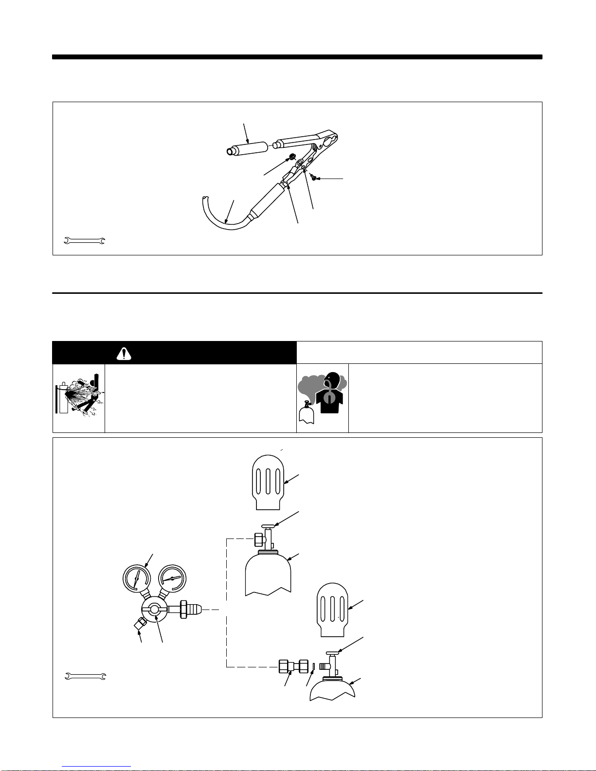
2-2. Installing Gas Supply
WARNING
CYLINDERS can explode if damaged.
• Keep cylinders away from welding and other
electrical circuits.
• Never touch cylinder with welding electrode.
• Always secure cylinder to running gear, wall, or
other stationary support.
1
6
5
3
4
2
Figure 2-1. Installing Work Clamp
BUILDUP OF SHIELDING GAS can harm
health or kill.
• Shut of f shielding gas supply when not in use.
1 Insulator
2 Bolt
3 Smaller Hole
4 Work Clamp Tabs
Bend tabs around work cable.
5 Work Cable From Unit
6 Nut
Ref. ST-025 190-D
warn4.1 9/91
Tools Needed:
1-1/8, 5/8 in
546
OR
Argon Gas Or
Mixed Gases
7 8
Chain gas cylinder to running gear,
wall, or other stationary support so
cylinder cannot fall and break off
1
2
3
1
2
3
valve.
1 Cap
2 Cylinder Valve
3 Cylinder
4 Regulator/Flowmeter
5 Gas Hose Connection
Fitting has 5/8-18 right-hand
threads.
6 Flow Adjust
Typical flow rate is 20 cfh (cubic feet
per hour). Check wire manufacturer’s recommended flow rate.
Make sure flow adjust is closed
when opening cylinder to avoid
damage to the flowmeter.
7CO2 Adapter
8 O-Ring
Install adapter with O-ring between
regulator/flowmeter and CO
cylinder.
ssb3.1* 5/94 – ST-158 697-A / Ref. ST-149 827-B
2
Figure 2-2. Typical CO2 Regulator/Flowmeter Installation
OM-174 470 Page 2
 Loading...