

Miller MU-1512VNR, MTT-1525NR, MTT-1512HR, MU-1525VHR, MU-1525VNR Owner's Manual
...
March
1988
FORM:
OM-i
559
Millerfi
ALE
COpy
~ETURN
TO
FOLDER
Effective
With
Style
No.
JJ-23
MODEL
MTT-1512HR
MTT-1525HR
MTT-1512NR
MTT-1525NR
MTF-1512VHR
MU-i
525VH
R
MU-1512VNR
MU-i
525
VN
R
MU-i
512
H
F
MU-1525HF
MU-1512NF
MU-i
525N
F
MU-1512VHF
MU-i
525
VH
F
MU-1512VNF
MU-i
525
VN
F
OWNERS
MANUAL
IMPORTANT
Read
and
understand
the
entire
contents
of
both
this
Miller
Electric
Mfg.Co.
manual
and
the
power
source
manual
used
with
this
unit,
with
special
emphasis
on
the
safety
material
throughout
both
manuals,
before
in-
~o.
Box
1079
stalling,
operating,
or
maintaining
this
equipment.
This
unit
and
these
instructions
are
for
use
only
by
persons
trained
and
experienced
in
the
Appleton,
WI
54912
USA
Te1
414-734-9821
safe
operation
of
welding
equipment.
Do
not
allow
untrained
persons
to
install,
operate,
or
maintain
this
unit.
Contact
your
distributor
if
you
do
not
fully
understand
these
instructions.
PRINTED
IN
U.S.A.
ADOmONAL
COPY
PRICE
35
CENTS
LIMITED
WARRANTY
EFFECTIVE:
FEBRUARY
16.
1988
This
warranty
supersedes
all
previous
MILLER
warranties
and
is
exclusive
withnoother
guarantees
or
warranties
expressed
or
implied.
LIMITED
WARRANTY
-
Subject
to
the
terms
and
condi-
In
the
case
of
Millers
breach
of
warranty
or
any
other
duty
tions
hereof,
Miller
Electric
Mfg.
Co.,
Appleton,
Wisconsin
with
respect
to
the
quality
of
any
goods,
the
exclusive
remedies
warrants
to
its
Distributor/Dealer
that
all
new
and
unused
therefore
shall
be,
at
Millers
option
(1)
repair
or
(2)
replacement
Equipment
furnishedbyMiller
is
free
from
defect
in
workman-
or,
where
authorized
in
writing
by
Miller
in
appropriate
cases,
(3)
ship
and
material
as
of
the
time
and
place
of
delivery
by
Miller.
the
reasonable
cost
of
repair
or
replacement
at
an
authorized
No
warranty
is
made
by
Miller
with
respect
to
engines,
trade
Miller
service
station
or
(4)
payment
of
or
credit
for
the
purchase
accessoriesorother
items
manufactured
by
others.
Such
price
(less
reasonable
depreciation
based
upon
actualuse)
upon
engines,
trade
accessories
and
other
items
are
sold
subject
to
return
of
the
goods
at
Customers
risk
and
expense.
MILLERs
the
warranties
of
their
respective
manufacturers,
if
any
.
All
option
of
repair
or
replacement
will
be
F.O.B.,
Factory,
at
~
engines
are
warrantedbytheir
manufacturer
for
one
year
from
Appleton,
Wisconsin,orF.O.B.,
at
a
MILLER
authorized
service
date
of
original
purchase,
except
Tecumseh
engines
which
facality,
therefore,
no
compensation
for
transportation
costs
of
have
a
two
year
warranty.
any
kind
willbeallowed.
Upon
receipt
of
notice
of
apparent
defect
or
failure,
Miller
shall
instruct
the
claimant
on
the
warranty
Except
as
specified
below,
Millers
warranty
does
not
apply
claim
procedures
to
be
followed.
to
components
having
normal
useful
life
of
less
than
one
(1)
year,
such
as
spot
welder
tips,
relay
and
contactor
points,
MILLERMATIC
parts
that
come
in
contact
with
the
welding
ANY
EXPRESS
WARRANTY
NOT
PROVIDED
HEREIN
AND
$J
wire
including
nozzles
and
nozzle
insulators
where
failure
does
ANY
IMPUED
WARRANTY,
GUARANTY
OR
REPRESENTA
P~
not
result
from
defect
in
workmanship
or
material.
T1ON
AS
TO
PERFORMANCE,
AND
ANY
REMEDY
FOR
BREACH
OF
CONTRACT
WHICH,
BUT
FOR
THIS
PROVISION,
~
Miller
shall
be
required
to
honorwarranty
claims
on
war-
MIGHT
ARISE
BY
IMPLICATION,
OPERATION
OF
LAW,
~
ranted
Equipment
in
the
event
of
failure
resulting
from
a
defect
CUSTOM
OF
TRADE
OR
COURSE
OF
DEALING,
INCLUDING
~
within
the
following
periods
from
the
date
of
delivery
of
Equip-
ANY
IMPUED
WARRANTY
OF
MERCHANTABIUTY
OR
OF
~J
ment
to
the
original
user:
FITNESS
FOR
PARTICULAR
PURPOSE,
WITH
RESPECT
TO
ANY
AND
ALL
EQUIPMENT
FURNISHED
BY
MILLER
IS
EX
~f
1.
Arc
welders,
p~r
sources,
robots,
and
components
.
1
year
CLUDED
AND
DISCLAIMED
BY
MILLER.
2.
Load
banks
1
year
~
3.
Original
main
power
rectifiers
3
years
(labor
-
1
year
only)
EXCEPT
AS
EXPRESSLY
PROVIDED
BY
MILLER
IN
i.)
4.
Allweldingguns,feeder/gunsandtorches
90days
WRITING,
MILLER
PRODUCTS
ARE
INTENDED
FOR
~J
5.
All
other
Millermatic
Feeders
1
year
ULTIMATE
PURCHASE
BY
COMMERCIAL/INDUSTRIAL
~
6.
Replacement
or
repair
parts,
exclusive
of
labor
..
60
days
USERS
AND
FOR
OPERATION
BY
PERSONS
TRAINED
AND
~
7.
Batteries
6
months
EXPERIENCED
IN
THE
USE
AND
MAINTENANCE
OF
WELDING
EQUIPMENT
AND
NOT
FOR
CONSUMERS
OR
provided
that
Miller
is
notified
in
writing
within
thirty
(30)
days
CONSUMER
USE.
MILLERS
WARRANTIES
DO
NOT
EXTEND
!~
of
the
date
of
such
failure.
TO,
AND
NO
RESELLER
IS
AUTHORIZED
TO
EXTEND
~
As
a
matter
at
general
policy
ony,
Miller
may
honor
claims
MILLERS
WARRANTIES
TO,
ANY
CONSUMER.
fl
submitted
by
the
original
user
within
the
foregoing
periods.
-.
......
..-...
-...
.
1
-
5.
Since
cess,
a.
WARNING
SECTION
1
-
_________
UNSAFE
PROCEDURES
OR
PRAC
TIGES
can
cause
serious
personal
injury
or
death.
Read,
understand,
and
follow
ALL
of
these
safety
rules
before
installing,
operating,orservicing
this
equipment.
Be
sure
that
all
end
users
of
this
equipment,
the
operator
and
helpers,
read
and
understand
these
safety
rules.
1
-
1.
PREVENT
ELECTRIC
SHOCK
Touching
live
electrical
parts
can
cause
severe
burns
to
the
body
or
fatal
shock.
Severity
of
electrical
shock
is
determinedbythe
path
and
amount
of
current
through
the
body.
Therefore:
a.
Do
not
touch
live
electrical
parts.
b.
Do
not
work
in
wet
or
damp
areas.
c.
Wear
dry
insulating
gloves
and
body
protection.
d.
Disconnect
all
power
before
installing
or
servic
ing
this
equipment.
e.
Turn
off
all
equipment
when
not
in
use.
f.
Properly
install
and
ground
the
welding
power
source
according
to
its
Owners
Manual
and
all
applicable
codes.
g.
Do
not
use
worn
or
damaged
cables
or
cables
that
are
too
small
or
poorly
spliced.
h.
Do
not
wrap
cabes
around
your
body.
i.
Do
not
touch
electrode
and
any
grounded
object
or
circuitatthe
same
time.
j.
Use
only
well-maintained
equipment.
Repair
or
replace
damaged
parts
at
once.
1
-
2.
PROVIDE
PROTECTION
FROM
FUMES
AND
GASES
Breathing
welding
fumes
and
gases
can
be
hazardous
to
your
health.
a.
Keep
your
head
out
of
the
fumes.
b.
Use
adequate
ventilationinthe
work
area
to
keep
fumes
and
gases
from
your
breathing
zone
and
the
general
work
area.
c.
If
ventilation
is
inadequate,
use
an
approved
breathing
device.
d.
Read
the
Material
Safety
Data
Sheets
(MSDSs)
and
the
manufacturers
instructions
for
any
materials
used.
SAFETY
RULES
1
-3.
PROTECT
EYES
AND
SKIN
FROM
ARC
RAYS;
PROTECT
EARS
FROM
NOISE
Arc
rays
from
the
welding
process
produce
intense
heat
and
strong
ultraviolet
rays
that
can
burn
eyes
and
skin.
Noise
from
some
processes
can
damage
hearing.
a.
Wear
a
welding
helmet
fitted
with
a
proper
filter
lens
(see
ANSI
Z49.1
for
detailed
information).
b.
Use
protective
screens
or
barriers
to
protect
others
from
flash
and
glare.
c.
Wear
protective
clothing
and
foot
protection.
d.
Always
wear
safety
glasses
or
safety
goggles
in
a
work
area.
1
-4.
PREVENT
FIRES
AND
BURNS
The
hot
workpiece,
hot
equipment,
other
hot
metal,
spatter,
and
arc
sparks
can
cause
fires
and
burns.
a.
Wear
correct
eye,
face,
and
body
protection
in
the
work
area.
b.
Allow
work
and
equipment
to
cool
before
handl
ing.
c.
Do
not
weld
near
combustible
material.
d.
Watch
for
fire,
and
keep
a
fire
extinguisher
near
by.
e.
For
additional
information,
refer
to
NFPA
Stan
dard
51
B,
Fire
Prevention
in
Use
of
Cutting
and
Welding
Processes,
available
from
the
National
Fire
Protection
Association,
Batterymarch
Park,
Quincy,
MA
02269.
PROTECT
COMPRESSED
GAS
CYLINDERS
gas
cylinders
are
normally
part
of
the
welding
pro
be
sure
to
treat
them
carefully.
Protect
compressed
gas
cylinders
from
excessive
heat,
mechanical
shocks,
and
arcs.
b.
Install
and
secure
cylinders
so
that
they
cannot
fall
or
tip
over
by
fastening
them
to
a
mounting
bracket,
wall,
or
other
stationary
support.
c.
Keep
cylinders
away
from
any
welding
or
other
electrical
circuits.
d.
Never
allow
a
welding
electrode
to
touch
any
cylinder.
aM-i
559
Page
1
1
-6.
PROVIDE
PROTECTION
FOR
SPECIAL
S
ITU
ATIONS
a.
Do
not
weld
or
Cut
containers
or
materials
which
have
heldorbeen
in
contact
with
hazardous
substances
unless
they
are
properly
cleaned
and
inspected.
b.
Do
not
weld
or
cut
painted
or
plated
parts
unless
special
ventilation
is
provided
to
remove
highly
toxic
fumes
or
gases.
c.
Since
welding
can
affect
pacemakers,
keep
all
pacemaker
wearers
out
of
the
work
area.
Have
them
consult
a
doctor
before
coming
near
a
welding
operation.
1
-
7.
PROVIDE
PROPER
EQUIPMENT
MAINTENANCE
Improperly
maintained
equipment
can
result
in
poor
work,
but
most
importantly
it
can
cause
physical
injury
or
death
through
fires
or
electrical
shock.
Therefore:
a.
Always
have
qualified
personnel
perform
the
in
stallation,
troubleshooting,
and
maintenance
work.
Do
not
perform
any
electrical
work
unless
you
are
fully
qualified.
b.
Before
performing
any
maintenance
work
inside
a
power
supply,
disconnect
the
power
supply
form
the
electrical
power
source.
c.
Maintain
cables,
grounding
wire,
connections,
power
cord,
and
power
supply
in
safe
working
order.
Do
not
operate
any
equipment
in
ques
tionable
condition.
d.
Do
not
abuse
any
equipment
or
accessories.
Keep
equipment
away
from
heat
sources
such
as
furnaces,
wet
conditions
such
as
water
puddles,
oil
or
grease,
corrosive
atmospheres,
and
incle
ment
weather.
e.
Keep
all
safety
devices,
guards,
panels,
and
covers
in
position
and
in
good
repair.
f.
Use
equipment
for
its
intended
purpose.
Do
not
modify
it
in
any
manner.
1
-8.
ADDITIONAL
SAFETY
INFORMATION
For
more
information
on
safe
practices
for
setting
up
and
operating
electric
welding
and
cutting
equipment
and
on
good
working
habits,
ask
your
welding
equip
ment
supplier.
The
following
publications,
which
are
I
available
from
the
American
Welding
Society,
550
N.W.
LeJuene
Rd.,
Miami,
FL
33126,
are
recommend
ed
to
you:
a.
Safety
in
Welding
and
Cutting
-
AWS
Z49.1
(ANSI)
b.
Recommended
Safe
Practices
for
Gas-Shielded
Arc
Welding
-
AWS
A6.1
c.
Recommended
Safe
Practices
for
the
Prepara
tion
for
Welding
and
Cutting
of
Containers
and
Piping
That
Have
Held
Hazardous
Substances
-
AWS
F4.1
d.
NFPA
Standard
516,
Fire
Prevention
in
Use
of
Cutting
and
Welding
Processes,
available
from
the
National
Fire
Protection
Association,
Bat
terymarch
Park,
Quincy,
MA
02269.
e.
NFPA
Standard
70,
National
Electrical
Code,
available
from
the
National
Fire
Protection
Association,
Batterymarch
Park,
Quincy,
MA
02269.
f.
ANSI
Standard
Z87.1,
Safe
Practice
for
Oc
cupation
and
Educational
Eye
and
Face
Protec
tion,
available
from
the
American
National
Standards
Institute,
1430
Broadway,
New
York,
NY
10018.
g.
OSHA
Standard
29
CFR,
Part
1910,
Subpart
Q,
Welding,
Cutting,
and
Brazing,
available
from
the
Superintendent
of
Documents,
U.S.
Govern
ment
Printing
Office,
Washington,
DC
20402.
h.
CSA
Standard
W117.2,
Code
for
Safety
in
Welding
and
Cutting,
available
from
the
Cana
dian
Standards
Association,
178
Rexdale
Blvd.,
Rexdale,
Ontario,
Canada
M9W
1
R3.
i.
See
also
the
Standards
Booklet
Index
in
the
welding
power
source
Owners
Manual.
.
.
OM-1559
Page
2
SECTION
1
-
INTRODUCTION
Rated
with
Gas
Lens
Collet
Body
Figure
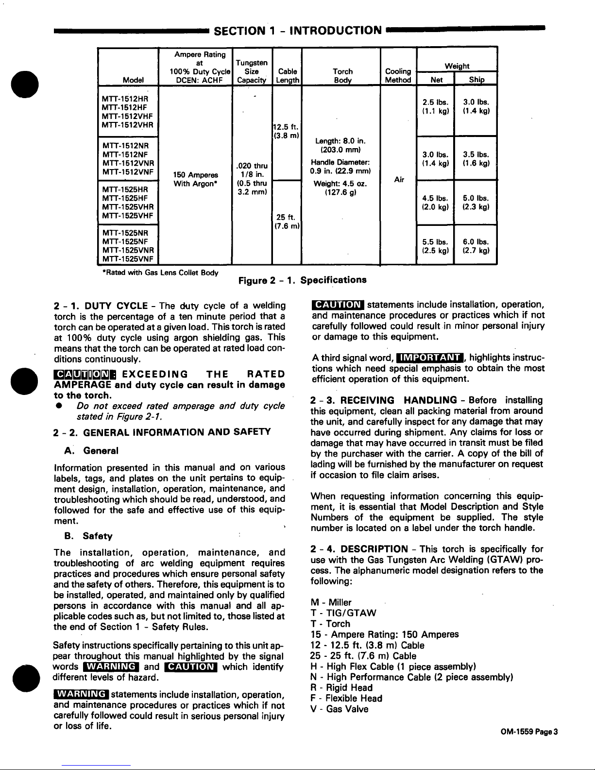
2-1.
Specifications
2
-2.
GENERAL
INFORMATION
AND
SAFETY
A.
General
B.
Safety
M
-
Miller
T
-
TIG/GTAW
T
-
Torch
15
-
Ampere
Rating:
150
Amperes
12
-
12.5
ft.
(3.8
m)
Cable
25
-
25
ft.
(7.6
m)
Cable
H
-
High
Flex
Cable
(1
piece
assembly)
N
-
High
Performance
Cable
(2
piece
assembly)
R
-
Rigid
Head
F
-
Flexible
Head
V
-
Gas
Valve
Ampere
Rating
Model
at
100%
Duty
Cycle
DCEN:
ACHF
Tungsten
Size
Capacity
Cable
£~~h
Torch
Body
Cooling
Method
Weight
Net
Ship
MTT-1512HR
MTT-1512HF
MTr-1512VHF
.
2.5
lbs.
(1.1
kg)
3.0
lbs.
(1.4
kg)
MTT-1512VHR
MTT-1512NR
MTT-1512NF
12.5
ft.
(3.8
m)
Length:
8.0
in.
(203.0
mm)
3.0
lbs.
3.5
lbs.
MTT-1512VNR
MTT1512VNF
MTT-1525HR
MTT-1525HF
150
Amperes
With
Argon
.020
thru
1/8
in.
(0.5
thru
3.2
mm)
Handle
Diameter:
0.9
in.
(22.9
mm)
Weight:
4.5
oz.
(127.6
9)
Air
(1.4
kg)
(1.6
kg)
4.5
lbs.
5.0
lbs.
MTT-1525VHR
(2.0
kg)
(2.3
kg)
MTT-1525VHF
MIT-i
525NR
25
ft.
(7.6
m)
MTT-i
525NF
5.5
lbs~
6.0
lbs.
MTT-1525VNR
MIT-i
525VNF
(2.5
kg)
(2.7
kg)
CAUTION
2
-
1.
DUTY
CYCLE
-
The
duty
cycle
of
a
welding
torchisthe
percentage
of
a
ten
minute
period
that
a
torch
can
be
operated
at
a
given
load.
This
torch
is
rated
at
100%
duty
cycle
using
argon
shielding
gas.
This
means
that
the
torch
can
be
operated
at
rated
load
con
ditions
continuously.
~
EXCEEDING
THE
RATED
AMPERAGE
and
duty
cycle
can
result
in
damage
to
the
torch.
Do
not
exceed
rated
amperage
and
duty
cycle
stated
in
Figure
2-1.
statements
include
installation,
operation,
and
maintenance
procedures
or
practices
which
if
not
carefully
followed
could
result
in
minor
personal
injury
or
damage
to
this
equipment.
A
third
signal
word,
Il~I~s]
~
highlights
instruc
tions
which
need
special
emphasis
to
obtain
the
most
efficient
operation
of
this
equipment.
2-3.
RECEIVING
HANDLING
-
Before
installing
this
equipment,
clean
all
packing
material
from
around
the
unit,
and
carefully
inspect
for
any
damage
that
may
have
occurred
during
shipment.
Any
claims
for
loss
or
damage
that
may
have
occurred
in
transit
must
be
filed
by
the
purchaser
with
the
carrier.
A
copy
of
the
bill
of
lading
will
be
furnished
by
the
manufacturer
on
request
if
occasiontofile
claim
arises.
When
requesting
information
concerning
this
equip
ment,
it
is.
essential
that
Model
Description
and
Style
Numbers
of
the
equipment
be
supplied.
The
style
number
is
located
on
a
label
under
the
torch
handle.
2-4.
DESCRIPTION
-
This
torch
is
specifically
for
use
with
the
Gas
Tungsten
Arc
Welding
(GTAW)
pro
cess.
The
alphanumeric
model
designation
referstothe
following:
Information
presented
in
this
manual
and
on
various
labels,
tags,
and
plates
on
the
unit
pertains
to
equip
ment
design,
installation,
operation,
maintenance,
and
troubleshooting
which
should
be
read,
understood,
and
followed
for
the
safe
and
effective
use
of
this
equip
ment.
The
installation,
operation,
maintenance,
and
troubleshooting
of
arc
welding
equipment
requires
practices
and
procedures
which
ensure
personal
safety
and
the
safety
of
others.
Therefore,
this
equipment
is
to
be
installed,
operated,
and
maintained
only
by
qualified
persons
in
accordance
with
this
manual
and
all
ap
plicable
codes
such
as,
but
not
limited
to,
those
listed
at
the
end
of
Section
1
-
Safety
Rules.
Safety
instructions
specifically
pertaining
to
this
unit
ap
pear
throughout
this
manual
highlighted
by
the
signal
words
____________
and
___________
which
identify
different
levels
of
hazard.
____________statements
include
installation,
operation,
and
maintenance
procedures
or
practices
which
if
not
carefully
followed
could
result
in
serious
personal
injury
or
lossoflife.
WARNING
WARNING
CAUTION
OM-1559
Page3
Assemble
torch
body
as
follows:
SECTION
3
-
INSTALLATION
1.
Instafl
collet
body
into
torch
body
making
sure
heat
shield
is
in
place.
2.
Install
cup
onto
collet
body.
3.
Install
standard
collet,
slotted
end
first,
through
back
of
torch
body
into
collet
body.Ifusing
reverse
collet,
install
collet
with
slotted
end
toward
backcap.
4.
Install
backcap
and
0-ring
(supplied
on
backcap)
onto
torch
body.
5.
Install
properly
prepared
tungsten
electrode
(see
Section
5-4)
through
front
of
collet
body
to
posi
tion
electrode
tip
outside
cup
rim.
Securely
tighten
backcap.
3
-2.
GAS
HOSE
CONNECTIONS
AND
GAS
VALVE
(If
applicable)
The
high
flex
cable
contains
the
power
cable
within
the
gas
hose.
The
high
flex
cable
has
a
3/8-24
male
right-
hand
fitting
(Figure
3-1).
To
install
high
flex
cable,
connect
high
flex
cable
fitting
to
power
cable
adapter.
Connect
a
suitable
length
of
gas
hose
from
power
cable
adapter
to
gas
valve
outlet
or
regulator/flowmeter
(Figures
3-2
and
3-3).
B.
High
Performance
Cable
Assembly
The
high
performance
cable
assemby
has
separate
power
cable
and
gas
hose.
The
gas
hose
has
a
5/8-18
male
right-hand
fitting
(Figure
3-1).
To
install
gas
hose,
connect
gas
hose
fitting
to
gas
valve
outlet
or
regulator/flowmeter.
Connect
gas
hose
(extra
hose
not
supplied)
from
gas
valve
inlet
to
regulator/flowmeter
(Figures
3-2
and
3-3).
.
0-ring
Collate
Torch
Body
Collet
Short
Backcap
Tungsten
Eiectrode
Power
Cable
Connector
Gas
Valve
applicable)
9~.*__
0-ring
Power
Cable~
Adapter
Handle
Gas
Hose
Fitting
High
Flex
Cable
Fitting
WARNING
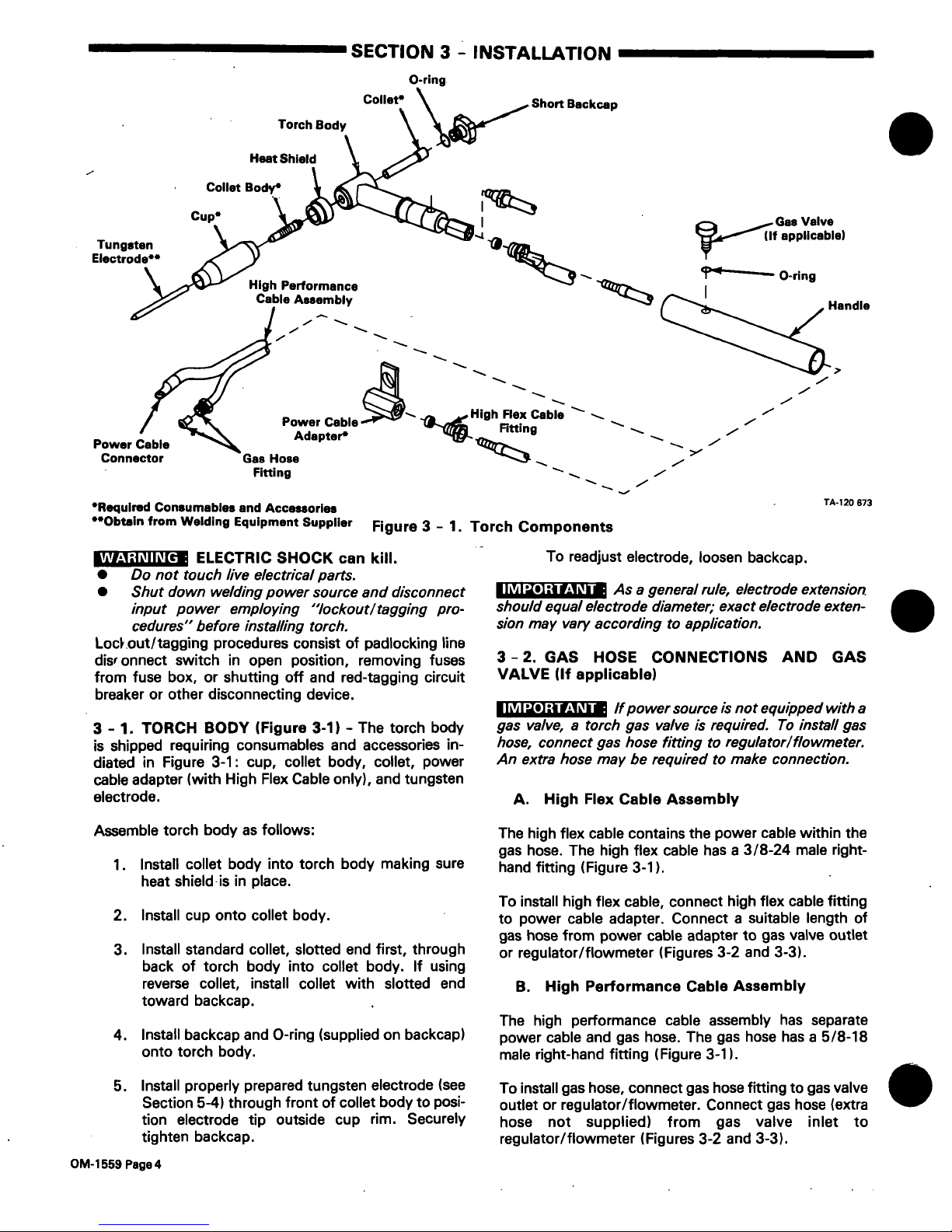
Required
Consumables
and
Accessories
*Obthin
from
Welding
Equipment
Supplier
Figure
3
-
1.
Torch
Components
>,
__________
ELECTRIC
SHOCK
can
kill.
Do
not
touch
live
electrical
parts.
Shut
down
welding
power
source
and
disconnect
input
power
employing
lockout/tagging
pro
cedures
before
installing
torch.
Loc~.out/tagging
procedures
consist
of
padlocking
line
dis
onnect
switch
in
open
position,
removing
fuses
from
fuse
box,
or
shutting
off
and
red-tagging
circuit
breaker
or
other
disconnecting
device.
TA-120
873
To
readjust
electrode,
loosen
backcap.
IMPORTANT
______________
As
a
general
rule,
electrode
extension
should
equal
electrode
diameter;
exact
electrode
exten
s/on
may
va,y
according
to
application.
3-1.
TORCH
BODY
(Figure
3-1)
-
The
torch
body
is
shipped
requiring
consumables
and
accessories
in
diated
in
Figure
3-1:
cup,
collet
body,
collet,
power
cable
adapter
(with
High
Flex
Cable
only),
and
tungsten
electrode.
IMPORTANT
______________
If
power
source
is
not
equipped
with
a
gas
valve,
a
torch
gas
valve
is
required.
To
install
gas
hose,
connect
gas
hose
fitting
to
regulator/flowmeter.
An
extra
hose
may
be
required
to
make
connection.
A.
High
Flex
Cable
Assembly
OM-1
559
Page
4
 Loading...