

Miller MTL-17 Owner's Manual
Millerfi
January
1994
Form:
OM-1563B
Effective
With
Style
No.
KB-8
OWNERS
MANUAL
MTL-1
7
Torches
~'
F'~~
r.
Read
and
follow
these
instructions
and
all
safety
blocks
carefully.
Have
only
trained
and
qualified
persons
install,
operate,
or
service
this
unit.
Give
this
manualtothe
operator.
~
.
For
help,
call
your
distributor
or:
MILLER
Electric
Mfg.
Co.,
P.O.
Box
1079,
Appleton,
WI
54912
414-734-9821
Call
your
distributor
if
you
do
not
understand
the
directions.
Air-Cooled
Torches
For
GTAW
Welding
Rated
At
150
Amperes
100%
Duty
Cycle
Using
Argon
Shielding
Gas
.020
Thru
1/8
in
(0.5
Thru
3.2
mm)
Tungsten
Size
Capacity
Includes
12-1/2
Or
25
ft
(3.8
or
7.6
m)
Cable
Remote
Contactor
And
Current
Control
Available
Tungsten
Electrode
And
Some
Torch
Parts
Needed
cover
7/93
ST-120
869
'
1993
MILLER
Electric
Mig.
co.
PRINTEDINUSA
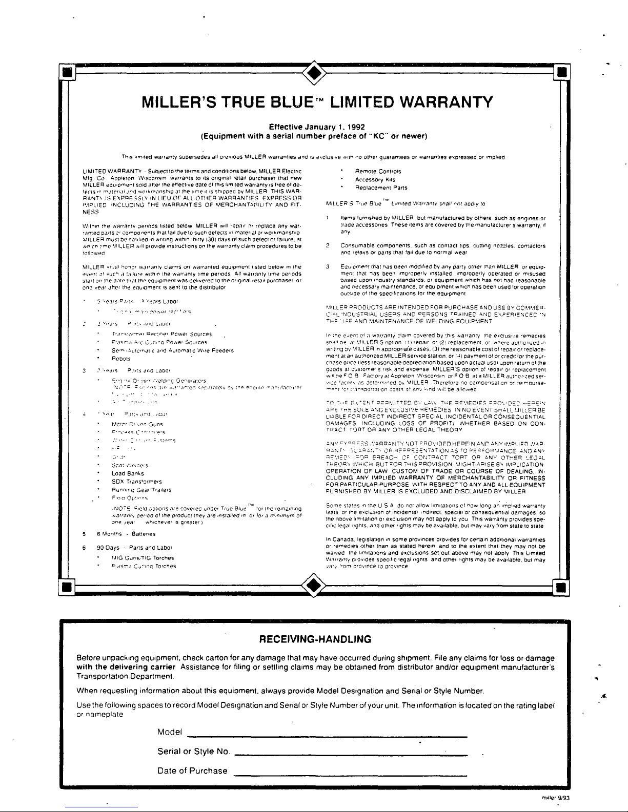
MILLERS
TRUE
BLU
ETM
LIMITED
WARRANTY
Effective
January
1.1992
(Equipment
with
a
serial
number
preface
of
KC
or
newer)
This
Limited
warranty
suoersedes
all
previous
MILLER
warranties
and
is
exclusive
with
ire
other
gualantees
Or
warlantres
expressed
or
implied
:I~I
LIMITED
WARRANTY
Sub~ect
to
the
terms
and
conditions
below.
MILLER
Electric
MIp
Co
Appleton
Wisconsin
warrants
to
its
original
retail
osrchaser
that
new
MILLER
equipment
sold
alter
the
ehectine
dale
Cl this
limited
warranty
is
tree
Cl
de
feels
ir
m,rteriLtl
rd
wnrknrannhip
at
the
time
it
is
shipped
by
MILLER
THIS
WAR.
PANTS
IS
b\PPESSLX
IN
LIEU
OF
ALL
OTHER
WARRANTIFS
EXPRESS
OR
l,tpI
lED
INCLUDING
THE
WARRANTIES
OP
MERCHANTAITILITY
AND
FIT.
NESS
Within
the
warrants
aerinds
listed
below
MILLER
will
ypair
or
replace
any
war
ranted
parts
oi
comooirents
that
laI
due
to
such
defects
in
material
or
wprbmansnio
stIllER
must
be
notified
in
writing
within
thirty
130)
days
ol
such
defectorlailure.
at
which
me
MILLER
will
pronide
instructions
on
the
warranty
claim
procedures
to
be
tollowelt
MILLER
un.~fI
honor
wariants
claims
on
warranted
eQuipment
listed
below
in
the
event
ar
suchaInure
withn
the
warranty
time
periods
All
warranty
time
periods
start
on
the
ante
that
the
equipment
was
delisered
to
the
original
retail
purchaser
or
one
veil
ahni
the
edsioment
is
sent
to
the
distributor
ears
Pt-tv
t
Vnii5
Lapor
2
-a-s
ii
.iint
LrtOrtr
T-arvtrrrrvr
Pn1,riyr
Power
Sources
Pacr,,rAcCutto
owei
Sources
Sn
Avtcrnat~c
and
Automatic
Wire
Pneders
3
r
-rain
Pris
ano
LAPOr
5
S
FT~D
..ni
,,nlrtiin
On~nratcrs
n
n
,~,,,-,
.~:n
ef,ltnct
vec,rrotnis
cvvenema
-Vr--iIlactmirvt
t,rcrcr
fli
.,
on
C,snc
S
cot
cv
e.ons
Load
Banks
SOY
Transcrrrers
Runnino
Gear
Trailers
F.e.c
flommns
NOTE
meId
c.ptions
are
covereo
unoen
True
Blue
or
the
remaining
viarranty
perod
of
the
product
they
are
installed
in
or
for
a
minimum
ol
onn
year
nhichever
is
greater
I
Months.Batteries
90
Days
Parts
and
Labor
taIG
OvnhiTIG
Torches
asnr,t
Cuimro
Torches
Remote
Controls
Accessory
Kits
Replacement
Parts
MILLERS
f-ire
Blue
Limited
Warranty
snaIl
not
apply
to
items
tsrnrshed
by
MILLER
but
manslactsred
by
others
ssch
as
engines
or
trade
accessories
These
items
are
cosered
by
the
manufacturers
warranty,
it
any
2
Consumable
components.
ssch
as
contact
tips,
cutting
noodles,
contactors
and
relaes
or
p~rt~
that
fail
due
to
normal
wear
3
Eaumpment
that
has
been
moditied
by
any
party
other
than
MtLLER
or
equip.
menl
that
nas
been
improperly
installed
improperly
operated
Pr
misused
based
upon
industry
standards.
or
equipment
which
has
npt
had
reasonable
arid
necessary
maintenance,
or
edsrpment
which
has
been
used
tot
oseratron
outside
o~
the
nqecrticatrons
ICr
the
eqsrpmenr
MIILEP
POOUCTS
ARE
INTENDED
FOR
PURCHASE
AND
USE
BYCOMMEP.
CISL
t4DUSTRIAL
USES
AND
ERSONS
cOAINED
AND
EXEEPiENCED
N
THy
ICE
AND
MAINTENANCE
OF
WELDING
EQUIPMENT
In
the
njent
o~
a
warranty
claim
covered
by
this
warranty
Inn
esclvsm:e
nmedies
ynaS
on
at
tILLER
S
option
Ill
repair
or
21
replacement,
or
where
authorized
.0
writing
W
MILLER
in
apprspria(e
cases.
13)
the
reasonable
cost
of
repair
or
replace
ment
at
an
autaorized
MILLER
sernrce
station,
or
tat
payment
of
or
credit
for
ne
pur
chase
price
less
reasorrabledepreciation
based
soon
actual
asel
upon
return
of
the
goods
Al
csstomer
a
risk
and
espense
MILLERS
oplion
ot
epair
or
replacement
will
ye
~O
B
Pactory
at
Appleton
Wisconsin
or
P0
B
at
a
MILLER
asthonoed
ser.
ice
acmlil,
an
cntn-mmind
Pu
MILLER
Thnrelorn
no
comcnnsat.on
Tr
rnmmpsrse
0
i,lnspOrtatmcn
costs
of
any
~ind
will
be
sllnwed
00
F
E.,~yrtT
PEAMIOTED
Wi
0LV
cuE
PE.IEDIES
500i,iDEC
FOCI,
APE
c,y
SOI,E
AND
EXCLUSIVE
REMEDIES
IN
NO
EVENT
SALL
MILLER
BE
LIABLE
OP
DIRECT
INDIRECT
SPECIAL,
INCIDENTAL
OR
CONSEQUENTIAL
DAMAGPS
INCLUDING
LOSS
OP
PRDFITI
WHETHER
BASED
ON
CON
TPACT
TORT OR
ANY
OTHER
LEGAL
THEORY
AN0
~~~ES
.TARPANTr
NOT
000VIDED
HEPEIN
AND
ANV
IMPLIED
NAP.
cANT.
0~AA,.
ILO
APOPESENTATION
A5
TO
EOPOAMANCE
AND
ANS
E,IED
~QP
PREACH
CF
COtITPACT
OpT
OP
ANN
OTHER
LEGAL
THEC1Pr
WHICH
BUT
FOB
THIS
ROVISION
MIGHT
ARISE
Es
IMPLICATION
OPERATION
OP
LAW
CUSTOM
OP
TRADE
OR
COURSE
OP
DEALING.
IN
CLUDING
ANY
IMPLIED
WARRANTY
OP
MERCHANTABILITY
OR
PITNESS
FOR
PARTICULAR
PURPOSE
WITH
RESPECT
TO
ANY
AND
ALL
EQUIPMENT
FURNISHED
BY
MILLER
IS
EXCLUDED
AND
DISCLAIMED
BY
MILLER
Somn
statna
n
ne
U
S
A
AP
nor
allow
limitations
cI
bow
lone
an
implied
warranty
lastsorthe
exclusion
CI
incidental
indirect,
special
or
consequential
damages.
so
the
aPove
limitation
or
exclusion
may
not
apply
to
you
Thi5
warranty
provides
spe
cific
tngal
rights,
and
other
rights
may
be
available.
Out
may
vary
1rpm
stale
to
state
In
Canada.
legislation
in
some
prosinces
prqsrdes
or
certain
additional
warrantIes
or
remedies
other
than
as
stated
herein,
andtothe
extent
that
they
may
not
be
waived
the
limitations
and
exclusions
set
oat
abose
may
not
apply
This
Lrmrted
Warranty
provides
specilrc
legal
rights
and
other
rights
may
be
anarlable.
but
may
-5r
l-sm
province
to
ptosmece
I
RECEIVING-HANDLING
Before
unpacking
equipment,
check
carton
for
any
damage
that
may
haMe
occurred
during
shipment.
File
any
claims
for
loss
or
damage
with
the
delivering
carrier
Assistance
for
filing
or
settling
claims
may
be
obtained
from
distributor
and/or
equipment
manufacturers
Transportation
Department.
When
requesting
information
about
this
equipment,
always
provide
Model
Designation
and
Serial
or
Style
Number.
Use
the
folloWing
spaces
to
record
Model
Designation
and
Serial
or
Style
Number
of
your
unit.
The
Information
is
tocafed
on
the
rating
label
or
nameplate
Model
__________
Serial
or
Style
No.
DateofPurchase
miller
9i93
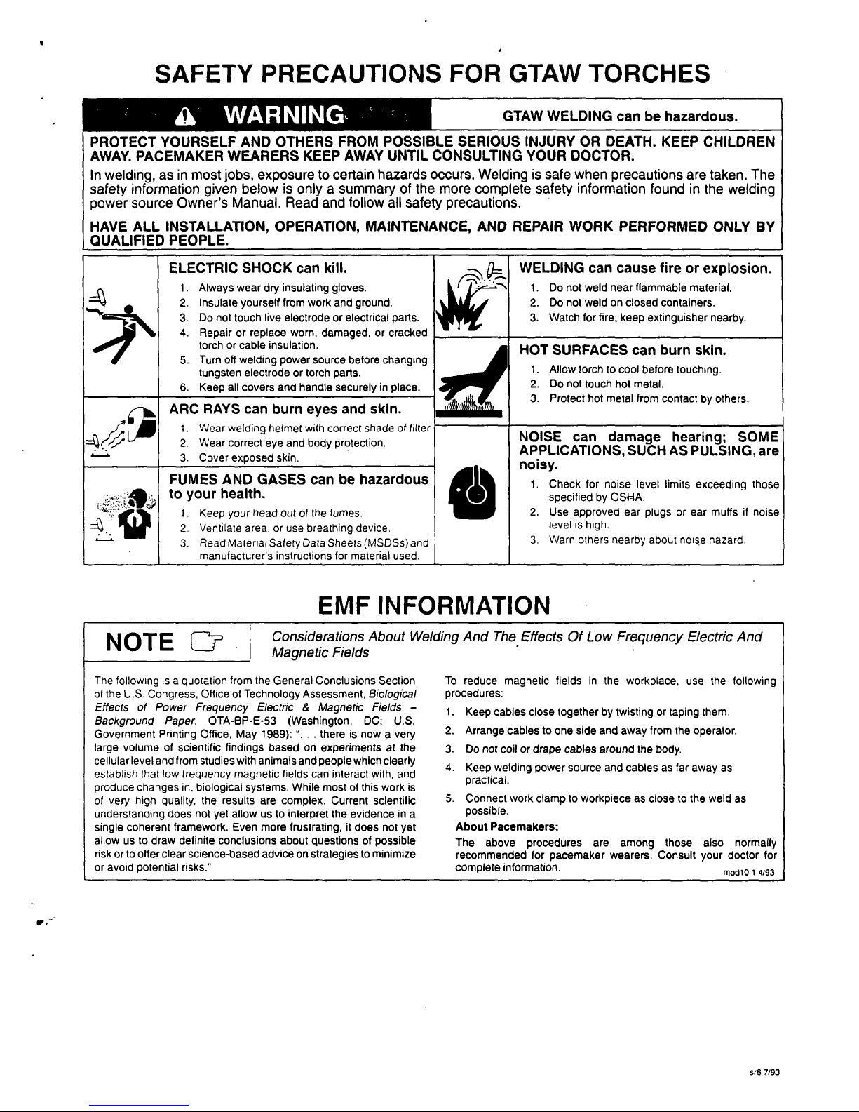
SAFETY
PRECAUTIONS
FOR
GTAW
TORCHES
ELECTRIC
SHOCK
can
kill.
1.
Always
wear
dry
insulating
gloves.
2.
Insulate
yourself
from
work
and
ground.
3.
Do
not
touch
live
electrodeorelectrical
parts.
4.
Repair
or
replace
worn,
damaged,
or
cracked
torch
or
cable
insulation.
5.
Turn
oft
welding
power
source
before
changing
tungsten
electrode
or
torch
parts.
6.
Keep
all
covers
and
handle
securely
in
ARC
RAYS
can
burn
eyes
and
skin.
1.
Wear
welding
helmet
with
correct
shade
of
filter.
2.
Wear
correct
eye
and
body
protection.
3.
Cover
exposed
skin.
FUMES
AND
GASES
can
be
hazardous
to
your
health.
1.
Keep
your
head
out
of
the
fumes.
2.
Ventilate
area,
or
use
breathing
device.
3.
Read
Material
Safety
Data
Sheets
(MSDSs)
and
manufacturers
instructions
for
material
used.
WELDING
can
cause
fire
or
explosion.
1.Donot
weld
near
flammable
material.
2.
Do
not
weldonclosed
containers.
3.
Watch
for
fire;
keep
extinguisher
nearby.
HOT
SURFACES
can
burn
skin.
1.
Allow
torch
to
cool
before
touching.
2.
Do
not
touch
hot
metal.
3.
Protect
hot
metal
from
contact
by
others.
NOISE
can
damage
hearing;
SOME
APPLICATIONS,
SUCH
AS
PULSING,
are
noisy.
1.
Check
for
noise
level
limits
exceeding
those
specified
by
OSHA.
2.
Use
approved
ear
plugs
or
ear
muffs
if
noise
level
is
high.
3.
Warn
others
nearby
about
nos~e
hazard.
EMF
INFORMATiON
a
WARNING
GTAW
WELDING
can
be
hazardous.
PROTECT
YOURSELF
AND
OTHERS
FROM
POSSIBLE
SERIOUS
INJURY
OR
DEATH.
KEEP
CHILDREN
AWAY.
PACEMAKER
WEARERS
KEEP
AWAY
UNTIL
CONSULTING
YOUR
DOCTOR.
In
welding,
as
in
most
jobs,
exposure
to
certain
hazards
occurs.
Welding
is
safe
when
precautions
are
taken.
The
safety
information
given
below
is
only
a
summary
of
the
more
complete
safety
information
found
in
the
welding
power
source
Owners
Manual.
Read
and
follow
all
safety
precautions.
HAVE
ALL
INSTALLATION,
OPERATION,
MAINTENANCE,
AND
REPAIR
WORK
PERFORMED
ONLY
BY
QUALIFIED
PEOPLE
______________________________
A
NOTE
~H
Considerations
About
We/ding
And
The
Effects
Of
Low
Frequency
Electric
And
Magnetic
Fields
The
following
is
a
quotation
from
the
General
Conclusions
Section
of
the
U.S.
Congress,
Office
of
Technology
Assessment,
Biological
Effects
of
Power
Frequency
Electric
&
Magnetic
Fields
Background
Paper,
OTA-BP-E-53
(Washington,
DC:
U.S.
Government
Printing
Office,
May
1989):.
.
.
there
is
now
a
very
large
volume
of
scientific
findings
based
on
experiments
at
the
cellular
level
and
from
studies
with
animals
and
people
which
clearly
establish
that
low
frequency
magnetic
fields
can
interact
with,
and
produce
changes
in,
biological
systems.
While
most
of this
work
is
of
very
high
quality,
the
results
are
complex.
Current
scientific
understanding
does
not
yet
allow
us
to
interpret
the
evidence
in
a
single
coherent
framework.
Even
more
frustrating,
it
does
not
yet
allow
us
to
draw
definite
conclusions
about
questions
of
possible
risk
or
to
offer
clear
science-based
advice
on
strategies
to
minimize
or
avoid
potential
risks.
To
reduce
magnetic
fields
in
the
workplace,
use
the
following
procedures:
1.
Keep
cables
close
together
by
twisting
or
taping
them.
2.
Arrange
cables
to
one
side
and
away
from
the
operator.
3.
Do
not
coil
or
drape
cables
around
the
body.
4.
Keep
welding
power
source
and
cablesasfar
away
as
practical.
5.
Connect
work
clamp
to
workpiece
as
close
to
the
weld
as
possible.
About
Pacemakers;
The
above
procedures
are
among
those
also
normally
recommended
for
pacemaker
wearers.
Consult
your
doctor
for
complete
information.
modlo,1
4/93
5t6
7/93
TABLE
OF
CONTENTS
SECTION
1
-
SAFETY
INFORMATION
.
1
SECTION
2-
SPECIFICATIONS
2-1.
Duty
Cycle
2
SECTION
3-
INSTALLATION
&
OPERATION
3-1.
Required
Torch
Parts
And
Torch
Assembly
2
3-2.
Adjusting
Flex-Lok
Head
3
3-3.
Connecting
Torch
4
SECTION
4-
MAINTENANCE
&
TROUBLESHOOTING
5
SECTION
5
TUNGSTEN
ELECTRODE
5-1.
Selecting
Tungsten
Electrode
6
5-2.
Preparing
Tungsten
7
SECTION
6
PARTS
LIST
Figure
6-1.
Complete
Torch
Assembly
8
Figure
6-2.
Consumable
Parts
9
Table
6-1.
Cross
Reference
to
Competitive
Model
10
OM-15636
1/94
SECTION
1
-
SAFETY
INFORMATION
Figure
1-1.
Safety
Information
SECTION
2-
SPECIFICATIONS
Table
2-1.
Welding
Torch
modl.t
2.93
Specification
Description
Model
Description
MT:
Miller
Torch;
L:
Flex
Lok;
17:
150
Ampere
Rating;
V:
Gas
Valve
12:12-1/2
ft(3.8
m)
Cable;
25:
25
ft
(7.6
m)
Cable;
1:
One-Piece
Cable
Example:
MTL-17-12
Miller
Torch;
Flex
Lok;
150
Ampere
Rating;
12-1/2
ft
(3.8
m);
One-Piece
Cable
Ampere
Rating
At
100%
Duty
Cycle
DCEN,
ACHF
150
Amperes
Using
Argon
Gas
Cooling
Method
Air
Cooling
Tungsten
Size
Capacity
.020
Thru
1/8
in
(0.5
Thru
3.2
mm)
Options
And
Accessories
Total
Weight
.
Torch
Body
Dimensions
And
Weight
See
Rear
Cover
12-1/2
ft
(3.8
m)
Cable
25
ft
(7.6
m)
Cable
12-1/2
ft
(3.8
m)
Cable
With
Gas
Valve
25
ft
(7.6
m)
Cable
With
Gas
Valve~
Net:
25
Ib(1.1
kg);
Ship:
3
lb
(1.4
kg)
Net:
4.5
lb(2
kg);
Ship:
5
lb
(2.3
kg)
Net:
2.5
lb(1.1
kg);
Ship:
3
lb
(1.4
kg)
Net:
5
lb(2.3
kg);
Ship:
5
lb
(2.3
kg)
Length:
8
in
(203
mm);
Handle
Diameter:
3/4
in
(19
mm)
Weight:
5.6
oz
(160
g)
Length:
8-3/4
in
(222
mm);
Handle
Diameter:
7/8
in
(23
mm);
Weight:
7.5
oz
(210
g)
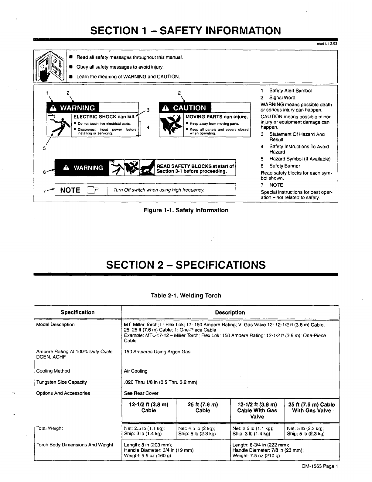
Read
all
safety
messages
throughout
this
manual.
Obey
all
safety
messages
to
avoid
injury.
Learn
the
meaning
of
WARNING
and
CAUTION.
1
2
\
2
\~
a
CAUTION
_______
3
_______
L
~
ELECTRIC
SHOCK
can
kill.
MOVING
PARTS
can
injure.
I
Do
not
touch
live
electrical
parts.
+1
Keep
away
trom
moving
parts.
Disconnect
input
power
beforejj_
~
Keep
all
panels
and
covers
closed
I
installing
or
servicing.
when
operating.
I
/
5
6
a
WARNING
READ
SAFETY
BLOCKS
at
start
of
SectIon
3-1
before
proceeding.
1
Safety
Alert
Symbol
2
Signal
Word
WARNING
means
possible
death
or
serious
injury
can
happen.
CAUTION
means
possible
minor
injuryorequipment
damage
can
happen.
3
Statement
Of
Hazard
And
Result
4
Safety
Instructions
To
Avoid
Hazard
5
Hazard
Symbol
(If
Available)
6
Safety
Banner
Read
safety
blocks
for
each
sym
bol
shown.
7
NOTE
Special
instructions
for
best
oper
ation
not
related
to
safety.
H
NOTE
~
Turn
Off
switch
when
using
high
frequency.
OM-1563
Page
1
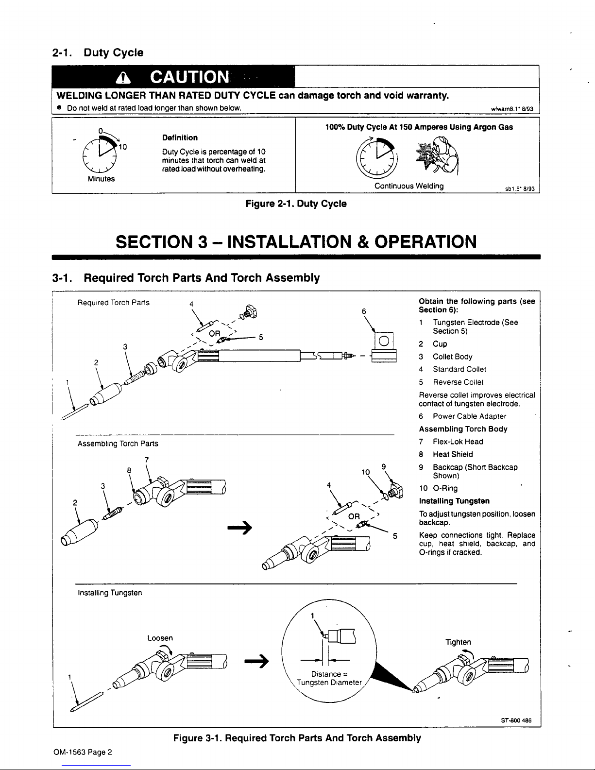
2-1.
Duty
Cycle
Obtain
the
following
parts
(see
Section
6):
1
Tungsten
Electrode
(See
Section
5)
2
Cup
3
Collet
Body
4
Standard
Collet
5
Reverse
Collet
Reverse
collet
improves
electrical
contact
of
tungsten
electrode.
6
Power
Cable
Adapter
Assembling
Torch
Body
7
Flex-Lok
Head
8
Heat
Shield
9
Backcap
(Short
Backcap
Shown)
10
0-Ring
Installing
Tungsten
To
adjust
tungsten
position,
loosen
backcap.
5
Keep
connections
tight.
Replace
cup,
heat
shield,
backcap,
and
0-rings
f
cracked.
Installing
Tungsten
-~
ST-800
486
Figure
3-1.
Required
Torch
Parts
And
Torch
Assembly
a
CAUTIONS
WELDING
LONGER
THAN
RATED
DUTY
CYCLE
can
damage
torch
and
void
warranty.
Do
not
weld
at
rated
load
longer
than
shown
below.
wfwarn8.1~
8/93
0
Definition
Duty
Cycle
is
percentage
of
10
-
10
rated
load
without
overheating.
minutes
that
torch
can
weld
at
Minutes
100%
D
uty
Cycle
At
150
Amperes
Using
Argo
Continuous
Welding
n
Gas
sb1.5~
8/93
Figure
2-1.
Duty
Cycle
SECTION
3-
INSTALLATION
&
OPERATION
3-1.
Required
Torch
Parts
And
Torch
Assembly
Required
Torch
Parts
4
3
Assembling
Torch
Parts
7
3
-~
10
OR
~-
Loosen
Tighten
OM-1563
Page
2
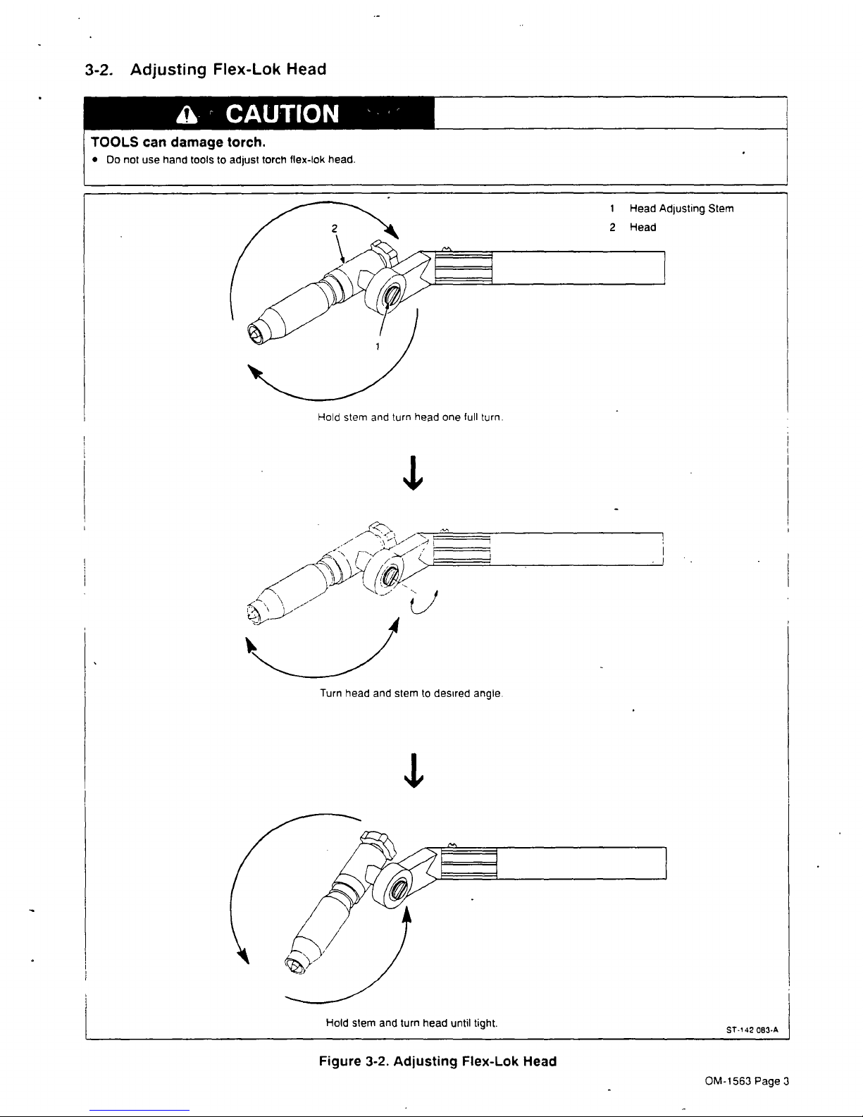
3-2.
Adjusting
Flex-Lok
Head
CAUTION
TOOLS
can
damage
torch.
Do
not
use
hand
tools
to
adjust
torch
flex-bk
head.
Hold
stem
and
turn
head
one
lull
turn.
1
Head
Adjusting
Stem
2
Head
Turn
head
and
stem
to
desired
angle.
Figure
3-2.
Adjusting
Flex-Lok
Head
ST-~42
083.A
~1~
Hold
stem
and
turn
head
until
tight.
OM-1563
Page
3
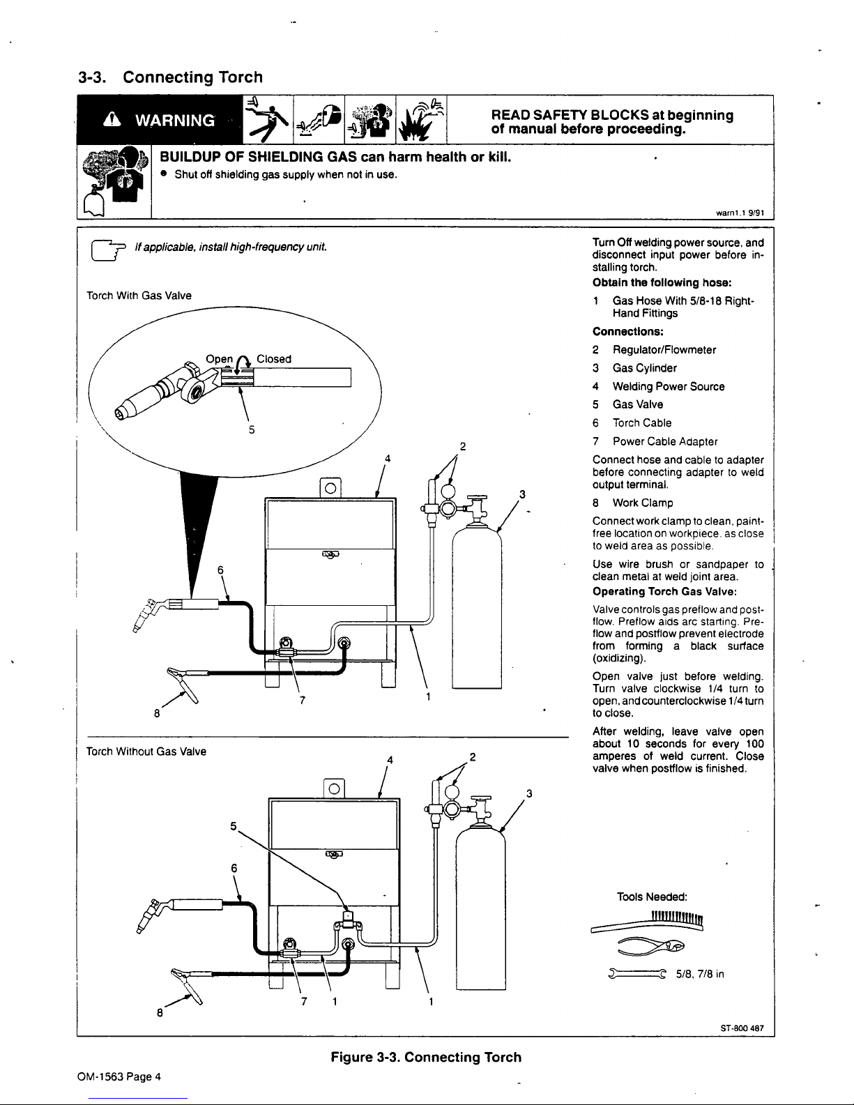
3-3.
Connecting
Torch
~
~
~
READ
SAFETY
BLOCKS
at
beginning
4jj~1
~
of
manual
before
proceeding.
BUILDUP
OF
SHIELDING
GAS
can
harm
health
or
kill.
0
Shut
off
shielding
gas
supply
when
not
in
use.
warnl.1
9/91
Turn
Off
welding
power
source,
and
If
applicable.
install
high-frequency
unit,
disconnect
input
power
before
in
stalling
torch.
Obtain
the
following
hose:
Torch
With
Gas
Valve
1
Gas
Hose
With
5/8-18
Right-
Hand
Fittings
Connections:
2
Regulator/Flowmeter
3
Gas
Cylinder
4
Welding
Power
Source
5
Gas
Valve
6
Torch
Cable
7
Power
Cable
Adapter
Connect
hose
and
cable
to
adapter
before
connecting
adapter
to
weld
output
terminal.
8
Work
Clamp
Connect
work
clamp
to
clean,
paint-
free
location
on
workpiece.
as
close
to
weld
area
as
possible.
Use
wire
brush
or
sandpaper
to
clean
metal
at
weld
joint
area.
Operating
Torch
Gas
Valve:
Valve
controls
gas
preflow
and
post
flow.
Preflow
aids
arc
starting.
Pre
low
and
postflow
prevent
electrode
from
forming
a
black
surface
(oxidizing).
Open
valve
just
before
welding.
Turn
valve
clockwise
1/4
turn
to
open,
and
counterclockwise
1/4
turn
to
close.
________
After
welding,
leave
valve
open
about
10
seconds
for
every
100
amperes
of
weld
current.
Close
valve
when
postflow
is
finished.
3
Tools
Needed:
~
5/8,
7/8
in
sT-BOO
487
Torch
Without
Gas
Valve
8
Figure
3-3.
Connecting
Torch
OM-1563
Page
4
SECTION
4
MAINTENANCE
&
TROUBLESHOOTING
4..
~.
~
V~
~
READSAF
of
manual
ETYBLOCKSatbeginning
before
proceeding.
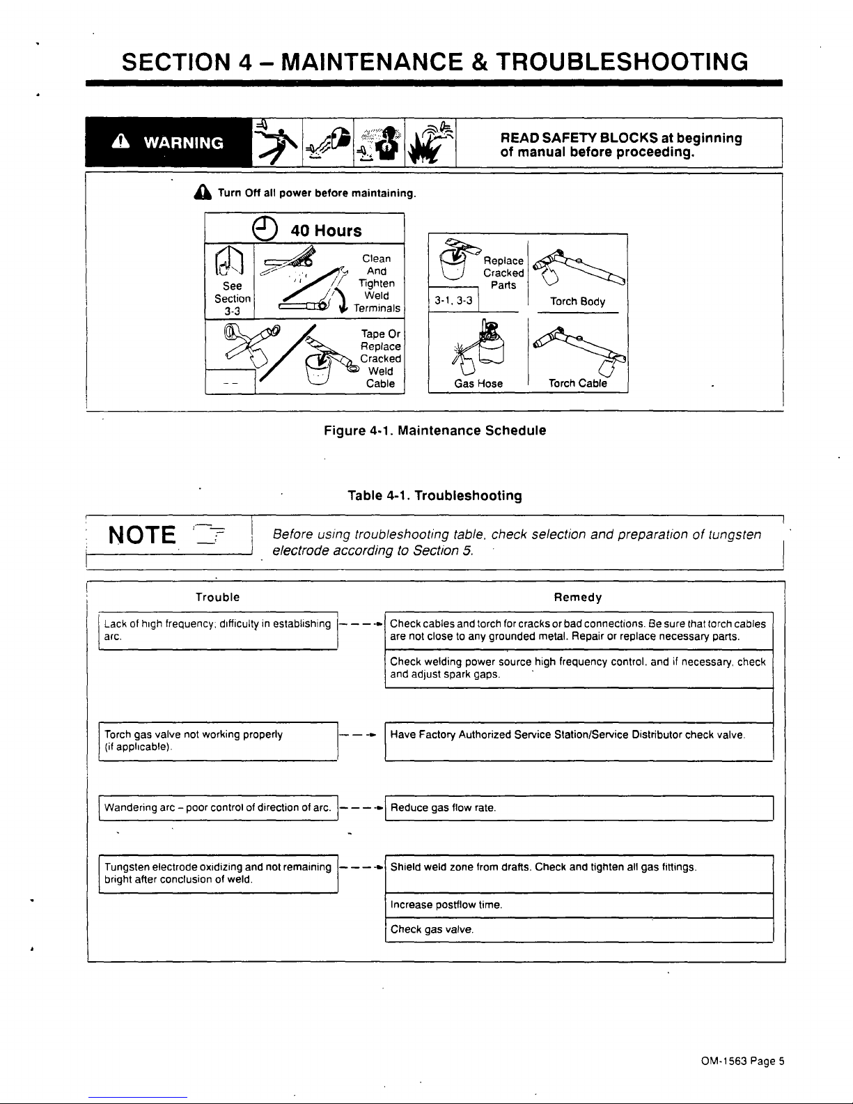
Figure
4-1.
Maintenance
Schedule
Table
4-1.
Troubleshooting
N
OTE
1
Before
using
troubleshooting
table,
check
selection
and
preparation
of
tungsten
electrode
according
to
Section
5.
Trouble
Remedy
Lack
of
high
frequency~
difficulty
in
establishing
~
Check
cables
and
torch
for
cracks
or
bad
connections.
Be
sure
that
torch
cables
arc.
Torch
gas
valve
not
working
properly
-~
are
not
close
to
any
grounded
metal.
Repair
or
replace
necessary
parts.
Check
welding
power
source
high
frequency
control.
and
if
necessary.
check
and
adjust
spark
gaps.
Have
Factory
Authorized
Service
Station/Service
Distributor
check
valve.
(if
applicable).
Wandering
arc
poor
control
of
direction
of
arc.
~
-..j
Reduce
gas
flow
rate.
Tungsten
electrode
oxidizing
and
not
remaining
-~
Shield
weld
zone
from
drafts.
Check
and
tighten
all
gas
fittings.
bright
after
conclusionofweld.
Increase
postflow
time.
Check
gas
valve.
Turn
Off
all
power
before
maintaining.
~~Replace
Cracked
Parts
3-1,
3-3
Torch
Body
Gas
Hose
Torch
Cable
.
OM-1563
Page
5
SECTION
5-
TUNGSTEN
ELECTRODE
mod2.
I
3/93
NOTE
~
Foradditional
information,
see
your
distributor
fora
handbook
on
the
Gas
Tungsten
I
Arc
Welding
(GTAW)
process.
Wear
clean
gloves
to
prevent
contamination
of
tungsten
electrode.
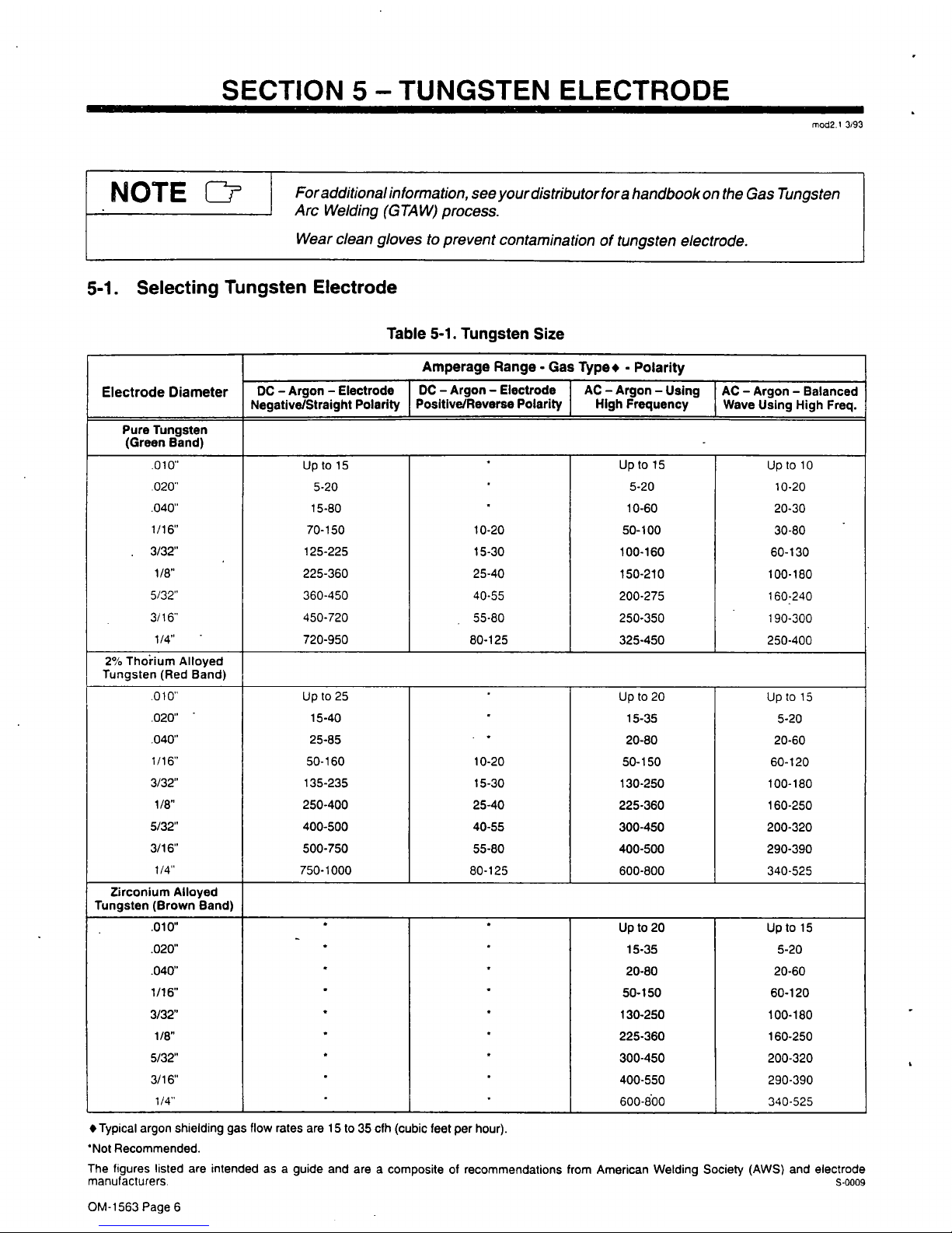
5-1.
Selecting
Tungsten
Electrode
Table
5-1.
Tungsten
Size
Electrode
Diameter
Amperage
Range.
Gas
Type,
-
Polarity
DC
Argon
Electrode
DC
Argon
Electrode
AC
Argon
Using
AC
Argon
Balanced
Negative/Straight
Polarity
Positive/Reverse
Polarity
High
Frequency
Wave
Using
High
Freq.
Pure
Tungsten
(Green
Band)
-
.010,
Up
to
15
.
Uptol5
UptolO
.020
5-20
5-20
10-20
.040
15-80
10-60
20-30
1/16
70-150
10-20
50-100
30-80
3/32
1/8
125-225
15-30
100-160
60-130
225-360
25-40
150-210
100-180
5/32
360450
4055
200275
160:240
3/16
450-720
.
55-80
250-350
190-300
1/4
720-950
80-125
325-450
250-400
2%
Thorium
Alloyed
Tungsten
(Red
Band)
010
Up
to
25
.
Up
to
20
Up
to
15
.020
15-40
.
15-35
5-20
.040
25-85
.
*
20-80
20-60
1/16
50-160
10-20
50-150
60-120
3/32
135-235
15-30
130-250
100-180
1/8
250-400
25-40
225-360
160-250
5/32
400-500
40-55
300-450 200-320
3/16
500-750
55-80
400-500 290-390
1/4
750-1000
80-125
600-800
340-525
Zirconium
Alloyed
Tungsten
(Brown
Band)
.010
Upto2O
Uptol5
.020
15-35
5-20
.040
20-80 20-60
1/16
50-150
60-120
3/32
130-250
100-180
1/8
225-360
160-250
5/32
300-450
200-320
3/16
400-550
290-390
1/4
.
600-800
340-525
Typical
argon
shielding
gas
flow
rates
are
15
to
35
cfh
(cubic
feet
per
hour),
Not
Recommended.
The
figures
listed
are
intended
as
a
guide
and
are
a
composite
of
recommendations
from
American
Welding
Society
(AWS)
and
electrode
manufacturers.
S-0009
OM-1563
Page
6
 Loading...