

Miller Millermatic 251 Technical Manual
TM-1326B 2006−10
Eff. w/Serial Number LB170597
Processes
MIG (GMAW) Welding
Flux Cored (FCAW) Welding
Description
Arc Welding Power Source
and Wire Feeder
R
Millermatic 251
Visit our website at
www.MillerWelds.com
File: MIG (GMAW)

TABLE OF CONTENTS
SECTION 1 − SAFETY PRECAUTIONS FOR SERVICING 1 . . . . . . . . . . . . . . . . . . . . . . . . . . . . . . . . . . . . . . . . . .
1-1. Symbol Usage 1 . . . . . . . . . . . . . . . . . . . . . . . . . . . . . . . . . . . . . . . . . . . . . . . . . . . . . . . . . . . . . . . . . . . . . . . .
1-2. Servicing Hazards 1 . . . . . . . . . . . . . . . . . . . . . . . . . . . . . . . . . . . . . . . . . . . . . . . . . . . . . . . . . . . . . . . . . . . .
1-3. California Proposition 65 Warnings 2 . . . . . . . . . . . . . . . . . . . . . . . . . . . . . . . . . . . . . . . . . . . . . . . . . . . . . . .
1-4. EMF Information 2 . . . . . . . . . . . . . . . . . . . . . . . . . . . . . . . . . . . . . . . . . . . . . . . . . . . . . . . . . . . . . . . . . . . . . .
SECTION 2 − DEFINITIONS 3 . . . . . . . . . . . . . . . . . . . . . . . . . . . . . . . . . . . . . . . . . . . . . . . . . . . . . . . . . . . . . . . . . . .
2-1. Symbols And Definitions 3 . . . . . . . . . . . . . . . . . . . . . . . . . . . . . . . . . . . . . . . . . . . . . . . . . . . . . . . . . . . . . . .
SECTION 3 − INSTALLATION 3 . . . . . . . . . . . . . . . . . . . . . . . . . . . . . . . . . . . . . . . . . . . . . . . . . . . . . . . . . . . . . . . . . .
3-1. Specifications 3 . . . . . . . . . . . . . . . . . . . . . . . . . . . . . . . . . . . . . . . . . . . . . . . . . . . . . . . . . . . . . . . . . . . . . . . .
3-2. Welding Power Source Duty Cycle And Overheating 4 . . . . . . . . . . . . . . . . . . . . . . . . . . . . . . . . . . . . . . . .
3-3. Volt-Ampere Curves 4 . . . . . . . . . . . . . . . . . . . . . . . . . . . . . . . . . . . . . . . . . . . . . . . . . . . . . . . . . . . . . . . . . . .
3-4. Connecting To Weld Output Terminals 5 . . . . . . . . . . . . . . . . . . . . . . . . . . . . . . . . . . . . . . . . . . . . . . . . . . . .
3-5. Installing Work Cable And Clamp 5 . . . . . . . . . . . . . . . . . . . . . . . . . . . . . . . . . . . . . . . . . . . . . . . . . . . . . . . .
3-6. Connecting Spoolmatic) 15A Or 30A Gun 6 . . . . . . . . . . . . . . . . . . . . . . . . . . . . . . . . . . . . . . . . . . . . . . . . .
3-7. Setting Gun Polarity For Wire Type 7 . . . . . . . . . . . . . . . . . . . . . . . . . . . . . . . . . . . . . . . . . . . . . . . . . . . . . .
3-8. Installing Gas Supply 7 . . . . . . . . . . . . . . . . . . . . . . . . . . . . . . . . . . . . . . . . . . . . . . . . . . . . . . . . . . . . . . . . . .
3-9. Installing Wire Spool And Adjusting Hub Tension 8 . . . . . . . . . . . . . . . . . . . . . . . . . . . . . . . . . . . . . . . . . . .
3-10. Positioning Jumper Links 8 . . . . . . . . . . . . . . . . . . . . . . . . . . . . . . . . . . . . . . . . . . . . . . . . . . . . . . . . . . . . . . .
3-11. Electrical Service Guide 9 . . . . . . . . . . . . . . . . . . . . . . . . . . . . . . . . . . . . . . . . . . . . . . . . . . . . . . . . . . . . . . . .
3-12. Selecting A Location And Connecting Input Power 10 . . . . . . . . . . . . . . . . . . . . . . . . . . . . . . . . . . . . . . . . . .
3-13. Threading Welding Wire 11 . . . . . . . . . . . . . . . . . . . . . . . . . . . . . . . . . . . . . . . . . . . . . . . . . . . . . . . . . . . . . . . .
3-14. Using Gun/Cable Holder 12 . . . . . . . . . . . . . . . . . . . . . . . . . . . . . . . . . . . . . . . . . . . . . . . . . . . . . . . . . . . . . . .
3-15. Weld Parameters 14 . . . . . . . . . . . . . . . . . . . . . . . . . . . . . . . . . . . . . . . . . . . . . . . . . . . . . . . . . . . . . . . . . . . . .
SECTION 4 − OPERATION 16 . . . . . . . . . . . . . . . . . . . . . . . . . . . . . . . . . . . . . . . . . . . . . . . . . . . . . . . . . . . . . . . . . . . .
4-1. Controls 16 . . . . . . . . . . . . . . . . . . . . . . . . . . . . . . . . . . . . . . . . . . . . . . . . . . . . . . . . . . . . . . . . . . . . . . . . . . . . .
4-2. Voltmeter And Wire Feed Speed Meter Operation 17 . . . . . . . . . . . . . . . . . . . . . . . . . . . . . . . . . . . . . . . . . .
SECTION 5 − THEORY OF OPERATION 18 . . . . . . . . . . . . . . . . . . . . . . . . . . . . . . . . . . . . . . . . . . . . . . . . . . . . . . . .
SECTION 6 − TROUBLESHOOTING 22 . . . . . . . . . . . . . . . . . . . . . . . . . . . . . . . . . . . . . . . . . . . . . . . . . . . . . . . . . . . .
6-1. Troubleshooting Table 22 . . . . . . . . . . . . . . . . . . . . . . . . . . . . . . . . . . . . . . . . . . . . . . . . . . . . . . . . . . . . . . . . .
6-2. Troubleshooting Circuit Diagram For Welding Power Source 24 . . . . . . . . . . . . . . . . . . . . . . . . . . . . . . . . .
6-3. Waveforms For Section 6-2 26 . . . . . . . . . . . . . . . . . . . . . . . . . . . . . . . . . . . . . . . . . . . . . . . . . . . . . . . . . . . . .
6-4. Main Control Board PC1 Testing Information (Use With Section 6-5) 28 . . . . . . . . . . . . . . . . . . . . . . . . . . .
6-5. Main Control Board PC1 Test Point Values 29 . . . . . . . . . . . . . . . . . . . . . . . . . . . . . . . . . . . . . . . . . . . . . . . .
6-6. Pre-Operational Check 31 . . . . . . . . . . . . . . . . . . . . . . . . . . . . . . . . . . . . . . . . . . . . . . . . . . . . . . . . . . . . . . . . .
SECTION 7 − MAINTENANCE 32 . . . . . . . . . . . . . . . . . . . . . . . . . . . . . . . . . . . . . . . . . . . . . . . . . . . . . . . . . . . . . . . . .
7-1. Routine Maintenance 32 . . . . . . . . . . . . . . . . . . . . . . . . . . . . . . . . . . . . . . . . . . . . . . . . . . . . . . . . . . . . . . . . . .
7-2. Unit Overload 32 . . . . . . . . . . . . . . . . . . . . . . . . . . . . . . . . . . . . . . . . . . . . . . . . . . . . . . . . . . . . . . . . . . . . . . . .
7-3. Changing Drive Roll and Wire Inlet Guide 33 . . . . . . . . . . . . . . . . . . . . . . . . . . . . . . . . . . . . . . . . . . . . . . . . .
7-4. Aligning Drive Rolls and Wire Guide 33 . . . . . . . . . . . . . . . . . . . . . . . . . . . . . . . . . . . . . . . . . . . . . . . . . . . . . .
7-5. Removing Knob From Front Panel 34 . . . . . . . . . . . . . . . . . . . . . . . . . . . . . . . . . . . . . . . . . . . . . . . . . . . . . . .
SECTION 8 − ELECTRICAL DIAGRAMS 35 . . . . . . . . . . . . . . . . . . . . . . . . . . . . . . . . . . . . . . . . . . . . . . . . . . . . . . . .
SECTION 9 − PARTS LIST 56 . . . . . . . . . . . . . . . . . . . . . . . . . . . . . . . . . . . . . . . . . . . . . . . . . . . . . . . . . . . . . . . . . . . . .
SECTION 1 − SAFETY PRECAUTIONS FOR SERVICING
Y Warning: Protect yourself and others from injury — read and follow these precautions.
1-1. Symbol Usage
OM-___ - Date, safety_stm 3/06
Means Warning! Watch Out! There are possible hazards
with this procedure! The possible hazards are shown in
the adjoining symbols.
Y Marks a special safety message.
. Means “Note”; not safety related.
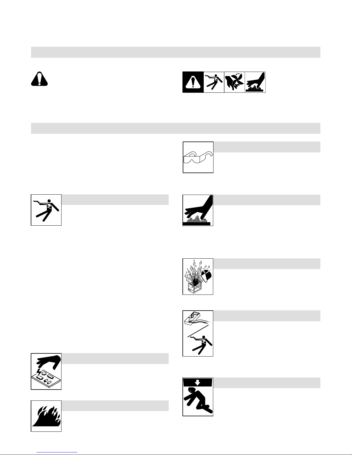
1-2. Servicing Hazards
Y The symbols shown below are used throughout this manual to
call attention to and identify possible hazards. When you see
the symbol, watch out, and follow the related instructions to
avoid the hazard.
Y Only qualified persons should service, test, maintain, and re-
pair this unit.
Y During servicing, keep everybody, especially children, away.
ELECTRIC SHOCK can kill.
D Do not touch live electrical parts.
D Turn Off welding power source and wire feeder
and disconnect and lockout input power using
line disconnect switch, circuit breakers, or by removing plug from receptacle, or stop engine before servicing unless the procedure specifically requires an energized unit.
D Insulate yourself from ground by standing or working on dry insulat-
ing mats big enough to prevent contact with the ground.
D Do not leave live unit unattended.
D If this procedure requires an energized unit, have only personnel
familiar with and following standard safety practices do the job.
D When testing a live unit, use the one-hand method. Do not put both
hands inside unit. Keep one hand free.
D Disconnect input power conductors from deenergized supply line
BEFORE moving a welding power source.
This group of symbols means Warning! Watch Out! possible
ELECTRIC SHOCK, MOVING PARTS, and HOT PARTS hazards.
Consult symbols and related instructions below for necessary actions
to avoid the hazards.
FLYING METAL or DIRT can injure eyes.
D Wear safety glasses with side shields or face
shield during servicing.
D Be careful not to short metal tools, parts, or
wires together during testing and servicing.
HOT PARTS can cause severe burns.
D Do not touch hot parts bare handed.
D Allow cooling period before working on
equipment.
D To handle hot parts, use proper tools and/or
wear heavy, insulated welding gloves and
clothing to prevent burns.
EXPLODING PARTS can cause injury.
D Failed parts can explode or cause other parts to
explode when power is applied to inverters.
D Always wear a face shield and long sleeves
when servicing inverters.
SIGNIFICANT DC VOLTAGE exists after removal of
input power on inverters.
D Turn Off inverter, disconnect input power, and discharge input
capacitors according to instructions in Troubleshooting Section before touching any parts.
STATIC (ESD) can damage PC boards.
D Put on grounded wrist strap BEFORE handling
boards or parts.
D Use proper static-proof bags and boxes to
store, move, or ship PC boards.
FIRE OR EXPLOSION hazard.
D Do not place unit on, over, or near combustible
surfaces.
D Do not service unit near flammables.
SHOCK HAZARD from testing.
D Turn Off welding power source and wire feeder
or stop engine before making or changing meter lead connections.
D Use at least one meter lead that has a self-
retaining spring clip such as an alligator clip.
D Read instructions for test equipment.
FALLING UNIT can cause injury.
D Use lifting eye to lift unit only, NOT running
gear, gas cylinders, or any other accessories.
D Use equipment of adequate capacity to lift and
support unit.
D If using lift forks to move unit, be sure forks are
long enough to extend beyond opposite side of
unit.
TM-1326 Page 1Millermatic 251

MOVING PARTS can cause injury.
H.F. RADIATION can cause interference.
D Keep away from moving parts such as fans.
D Keep away from pinch points such as drive
rolls.
D Have only qualified persons remove doors,
panels, covers, or guards for maintenance as
necessary.
D Keep hands, hair, loose clothing, and tools
away from moving parts.
D Reinstall doors, panels, covers, or guards
when maintenance is finished and before re-
connecting input power.
MAGNETIC FIELDS can affect pacemakers.
D Pacemaker wearers keep away from servicing
areas until consulting your doctor.
OVERUSE can cause OVERHEATING.
D Allow cooling period; follow rated duty cycle.
D Reduce current or reduce duty cycle before
starting to weld again.
D Do not block or filter airflow to unit.
D High-frequency (H.F.) can interfere with radio
navigation, safety services, computers, and
communications equipment.
D Have only qualified persons familiar with
electronic equipment install, test, and service
H.F. producing units.
D The user is responsible for having a qualified electrician prompt-
ly correct any interference problem resulting from the installation.
D If notified by the FCC about interference, stop using the
equipment at once.
D Have the installation regularly checked and maintained.
D Keep high-frequency source doors and panels tightly shut, keep
spark gaps at correct setting, and use grounding and shielding to
minimize the possibility of interference.
READ INSTRUCTIONS.
D Use Testing Booklet (Part No. 150 853) when
servicing this unit.
D Consult the Owner’s Manual for welding safety
precautions.
D Use only genuine replacement parts from the
manufacturer.
1-3. California Proposition 65 Warnings
Y Welding or cutting equipment produces fumes or gases which
contain chemicals known to the State of California to cause
birth defects and, in some cases, cancer. (California Health &
Safety Code Section 25249.5 et seq.)
Y Battery posts, terminals and related accessories contain lead
and lead compounds, chemicals known to the State of
California to cause cancer and birth defects or other
reproductive harm. Wash hands after handling.
1-4. EMF Information
Considerations About Welding And The Effects Of Low Frequency
Electric And Magnetic Fields
Welding current, as it flows through welding cables, will cause electromagnetic fields. There has been and still is some concern about such
fields. However, after examining more than 500 studies spanning 17
years of research, a special blue ribbon committee of the National
Research Council concluded that: “The body of evidence, in the
committee’s judgment, has not demonstrated that exposure to powerfrequency electric and magnetic fields is a human-health hazard.”
However, studies are still going forth and evidence continues to be
examined. Until the final conclusions of the research are reached, you
may wish to minimize your exposure to electromagnetic fields when
welding or cutting.
To reduce magnetic fields in the workplace, use the following
procedures:
For Gasoline Engines:
Y Engine exhaust contains chemicals known to the State of
California to cause cancer, birth defects, or other reproductive
harm.
For Diesel Engines:
Y Diesel engine exhaust and some of its constituents are known
to the State of California to cause cancer, birth defects, and
other reproductive harm.
1. Keep cables close together by twisting or taping them.
2. Arrange cables to one side and away from the operator.
3. Do not coil or drape cables around your body.
4. Keep welding power source and cables as far away from operator as practical.
5. Connect work clamp to workpiece as close to the weld as possible.
About Pacemakers:
Pacemaker wearers consult your doctor before welding or going near
welding operations. If cleared by your doctor, then following the above
procedures is recommended.
TM-1326 Page 2 Millermatic 251
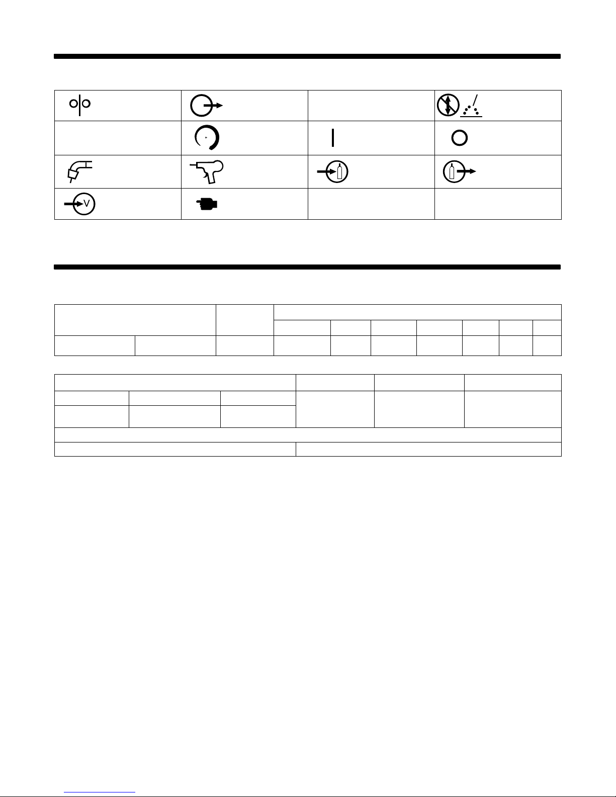
SECTION 2 − DEFINITIONS
Rated Output
2-1. Symbols And Definitions
V
Wire Feed Output
Volts Increase On Off
Gas Metal Arc
Welding (GMAW)
Gun
Voltage Input Press To Reset
Wire Feed Spool
Gun
X
U
0
Duty Cycle
Gas Input Gas Output
Rated No-Load
Voltage (Average)
SECTION 3 − INSTALLATION
3-1. Specifications
Max. Open
Circuit
Voltage
250 A at 28 VDC,
40% Duty Cycle
Solid Steel Stainless Steel Flux Cored 25−700 IPM
.023 − .045 in
(0.6 − 1.2 mm)
* While idling
Operating Temperature Range − −20C to +40C Storage Temperature Range − -30C to + 50C
200 A at 28 VDC,
60% Duty Cycle
Wire Type and Diameter Wire Feed Speed Dimensions Net Weight
.023 − .045 in
(0.6 − 1.2 mm)
38 48
.030 − .045 in
(0.8 − 1.2 mm)
Amps Input at Rated Output (60% Duty Cycle), 50 or 60 Hz, Single-Phase
200 (208) V 230 V 400 V 460 V 575 V KVA KW
2.3*
(.65−17.8 m/min) W: 19 in (483 mm)
42
2*
24
1.2*
H: 32 in (813 mm)
D: 39 in (991 mm)
21
1*
17
0.8*
Do Not Switch
While Welding
9.8
0.46*
215 lb
(98 kg)
0.13*
7.5
TM-1326 Page 3Millermatic 251

3-2. Welding Power Source Duty Cycle And Overheating
500
450
400
350
300
250
200
150
WELD AMPERES
100
50
10 20 30 40 50 60 70 80 90 100
% DUTY CYCLE
Duty Cycle is percentage of 10
minutes that unit can weld at rated
load without overheating.
If unit overheats, Thermistor (T)
opens, output stops, and cooling
fan runs. Wait fifteen minutes for
unit to cool. Reduce amperage or
voltage, or duty cycle before
welding.
Y Exceeding duty cycle can
damage unit and void
warranty.
60% Duty Cycle At 200 Amperes
6 Minutes Welding 4 Minutes Resting
Overheating
3-3. Volt-Ampere Curves
35
30
25
0
Minutes
15
40% Duty Cycle At 250 Amperes
4 Minutes Welding 6 Minutes Resting
A or V
OR
Reduce Duty Cycle
duty1 4/95 − 150 215-A
1
1 Normal Volt-Ampere Curves
The volt-ampere curves show the
normal minimum and maximum
voltage and amperage output
capabilities of the welding power
source. Curves of other settings fall
between the curves shown.
20
VOLTS
15
10
5
0
0 100 200 300 400
TM-1326 Page 4 Millermatic 251
AMPERES
ssb1.1 10/91 − 196 844 / S-0700
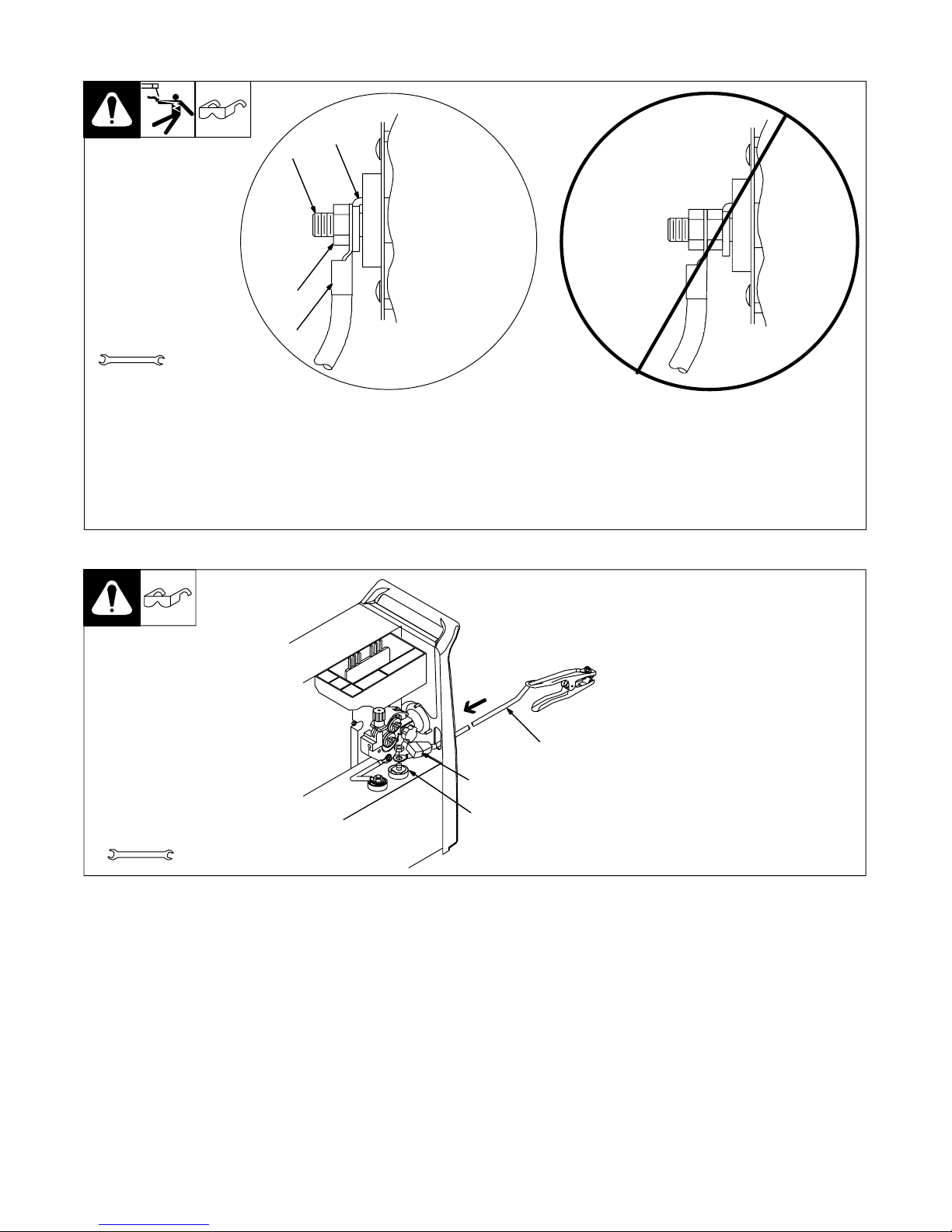
3-4. Connecting To Weld Output Terminals
4
1
Do not place
anything between
weld cable terminal
and copper bar.
2
Tools Needed:
3/4 in (19 mm)
Y Turn off power before connecting to
weld output terminals.
Y Failure to properly connect weld
cables may cause excessive heat
and start a fire, or damage your machine.
3
Correct Installation
1 Weld Output Terminal
2 Supplied Weld Output Terminal Nut
3 Weld Cable Terminal
4 Copper Bar
Remove supplied nut from weld output ter-
3-5. Installing Work Cable And Clamp
803 778-A
Incorrect Installation
minal. Slide weld cable terminal onto weld
output terminal and secure with nut so that
weld cable terminal is tight against copper
bar. Do not place anything between weld
cable terminal and copper bar. Make
sure that the surfaces of the weld cable
terminal and copper bar are clean.
1 Work Cable
2 Boot
Route cable through front panel
opening. Slide boot onto work
cable.
3 Negative (−) Output Terminal
Connect cable to terminal and
cover connection with boot.
Close door.
1
Tools Needed:
3/4 in
2
3
Ref. 802 474-E
TM-1326 Page 5Millermatic 251

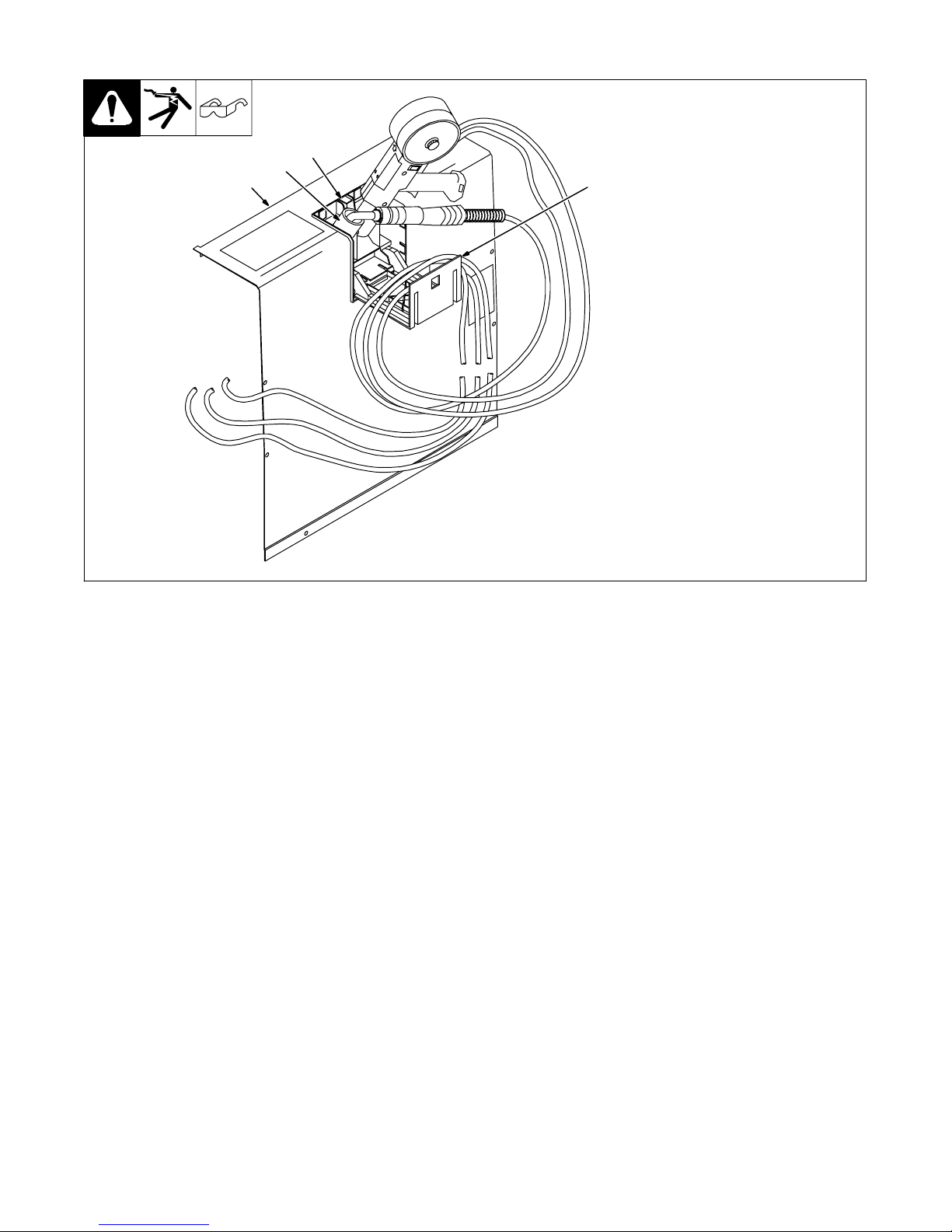
3-6. Connecting Spoolmatic) 15A Or 30A Gun
1
2
3
1 Gun Trigger Plug
Insert plug into receptacle, and
tighten threaded collar.
2 Weld Cable
3 Shielding Gas Hose
Route weld cable through opening
in front panel.
Route gas hose along side panel.
4 Positive Weld Output Terminal
Connect weld cable to weld output
terminal.
5 Regulator/Flowmeter
6 Y-Adapter Fitting
Route shielding gas hose up to
regulator/flowmeter. Connect gas
hose to Y-adapter fitting on regulator/flowmeter.
. Two welding guns may be
connected to the welding
power source at the same time,
but only one welding gun may
be in use at any one time. If the
triggers of both welding guns
are pulled at the same time, the
weld output and wirefeed motor
are disabled.
2
Tools Needed:
3/4, 5/8 in
5
6
4
3
804 455-A
TM-1326 Page 6 Millermatic 251
3-7. Setting Gun Polarity For Wire Type
Changing Polarity
1 Polarity Changeover Label
Information
Always read and follow manufacture’s
recommended polarity.
Wire Drive
Assembly Lead
+
Positive Terminal
Shown as shipped − Electrode Positive (DCEP): For
solid steel, stainless steel, aluminum, or flux core with
gas wires (GMAW).
Electrode Negative (DCEN): Reverse lead connections
at terminals from that shown above for gasless flux core
wires (FCAW). Drive assembly becomes negative.
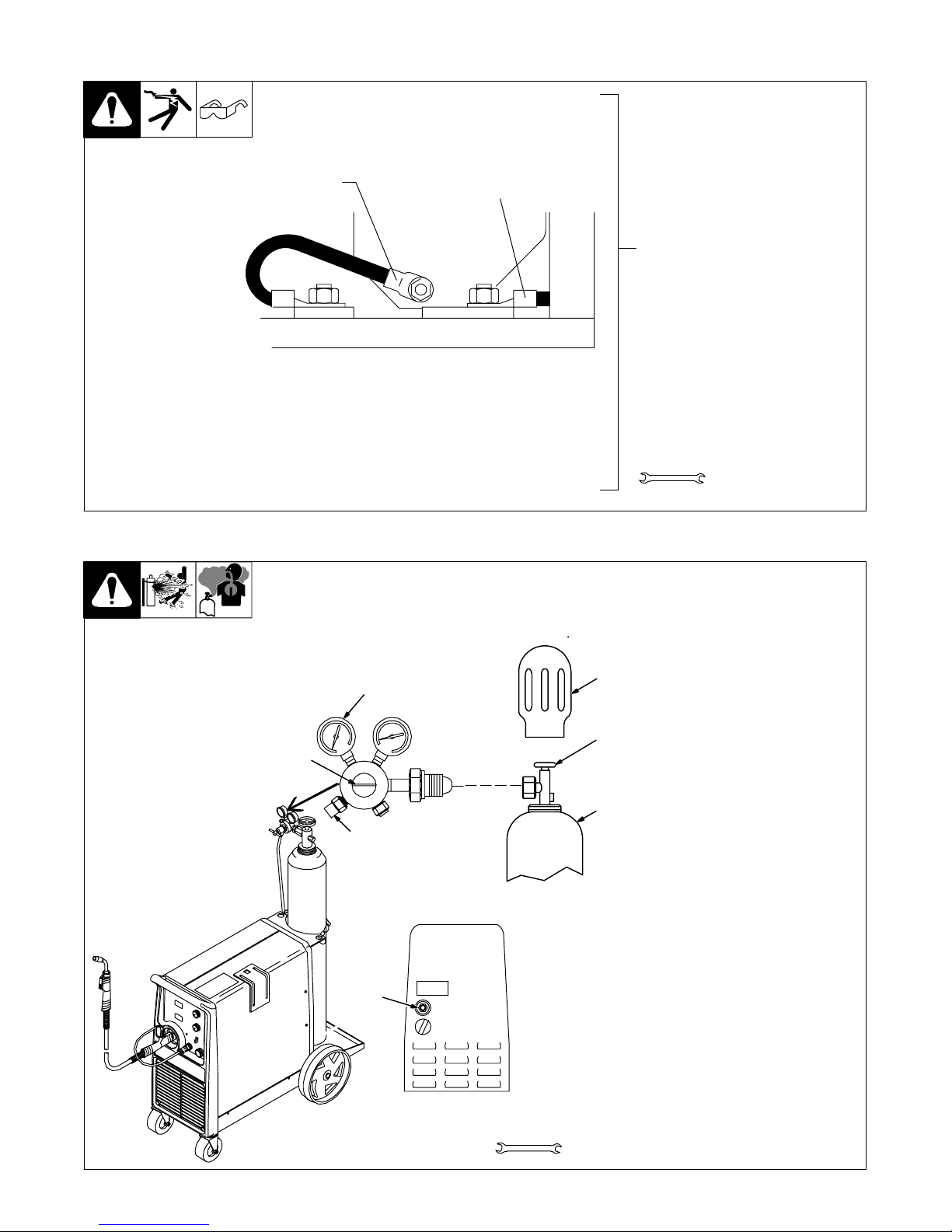
3-8. Installing Gas Supply
. DO NOT use Argon/Mixed gas regulator/flowmeter
with CO2 shielding gas. See Parts List for optional
CO2 gas regulator/flowmeter.
4
7
5
Work Clamp Lead
1
D
D
-
Negative Terminal
3/4, 11/16 in
Ref. 190 821-A
Obtain gas cylinder and chain to
running gear, wall, or other
stationary support so cylinder
cannot fall and break off valve.
1 Cap
2 Cylinder Valve
1
2
3
Argon Gas Or
Mixed Gas
6
Remove cap, stand to side of
valve, and open valve slightly. Gas
flow blows dust and dirt from valve.
Close valve.
3 Cylinder
4 Regulator/Flowmeter
Install so face is vertical.
5 Regulator/Flowmeter Gas
Hose Connection
6 Welding Power Source Gas
Hose Connection
Connect customer supplied gas
hose between regulator/flowmeter
gas hose connection, and fitting on
rear of welding power source.
7 Flow Adjust
Typical flow rate is 20 cfh (cubic
feet per hour). Check wire
manufacturer’s recommended
flow rate.
Rear Panel
Tools Needed:
1-1/8, 5/8 in
802 028-A / Ref. 802 477-B
TM-1326 Page 7Millermatic 251
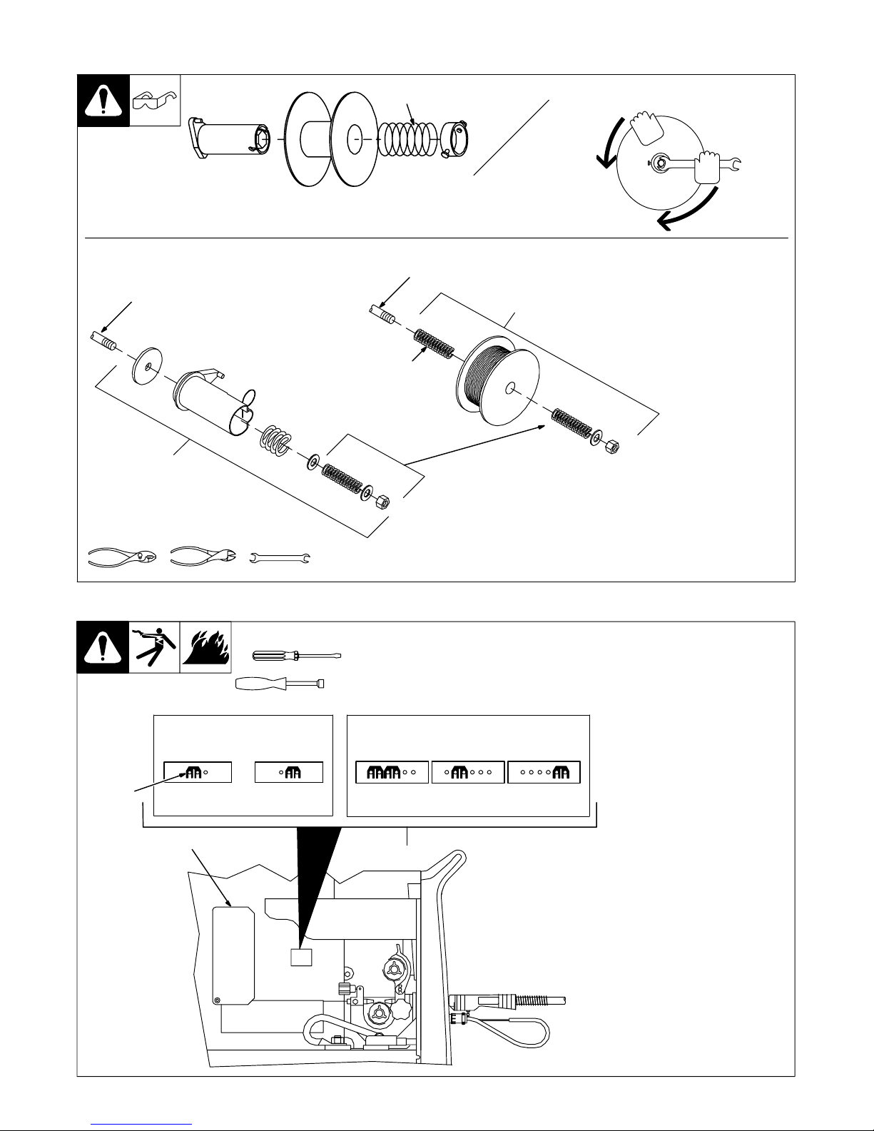
3-9. Installing Wire Spool And Adjusting Hub Tension
Installing 1 Or 2 lb Wire Spool
Spindle
Remove these
components
from spindle.
Use compression spring
with 8 in (200 mm) spools.
Spindle
Order extra spring
Part No. 186 437
Install these
components
onto spindle.
When a slight force is needed
to turn spool, tension is set.
To install either a 1 lb or 2 lb wire
spool, follow the procedure as
shown in the illustration.
Tools Needed:
15/16 in
3-10. Positioning Jumper Links
Tools Needed:
200VOLTS 230VOLTS
3
153 980-C
1
3/8 in
230VOLTS 460VOLTS 575VOLTS
2
072573-B / 802 922
Check input voltage available at
site.
1 Jumper Links Access Door
Open door.
2 Jumper Link Label
Check label − only one is on unit.
3 Input Voltage Jumper Links
Move jumper links to match input
voltage.
Close and secure access door.
144 916-D
TM-1326 Page 8 Millermatic 251
Ref. 802 476-D

3-11. Electrical Service Guide
Input Voltage 200 230 400 460 575
Input Amperes At Rated Output 48 42 24 21 17
Max Recommended Standard Fuse Or Circuit Breaker Rating In Amperes
2
Circuit Breaker 1, Time-Delay
Normal Operating
Min Input Conductor Size In AWG
4
Max Recommended Input Conductor Length In Feet (Meters)
Min Grounding Conductor Size In AWG
4
Reference: 2005 National Electrical Code (NEC) (including article 630)
1 Choose a circuit breaker with time-current curves comparable to a Time Delay Fuse.
2 “Time-Delay” fuses are UL class “RK5” .
3 “Normal Operating” (general purpose − no intentional delay) fuses are UL class “K5” (up to and including 60 amp), and UL class “H” ( 65 amp and
above).
4 Conductor data in this section specifies conductor size (excluding flexible cord or cable) between the panelboard and the equipment per NEC Table
310.16. If a flexible cord or cable is used, minimum conductor size may increase. See NEC Table 400.5(A) for flexible cord and cable requirements.
Y Caution: Failure to follow these fuse and circuit breaker recommendations could create an electric shock or fire hazard. These
recommendations are for a dedicated branch circuit that applies to the rated output and duty cycle of the welding power source.
60 50 30 25 20
3
70 60 35 30 25
8 8 12 12 14
96
(29)
127
(39)
156
(47)
8 10 12 12 14
206
(63)
209
(64)
TM-1326 Page 9Millermatic 251
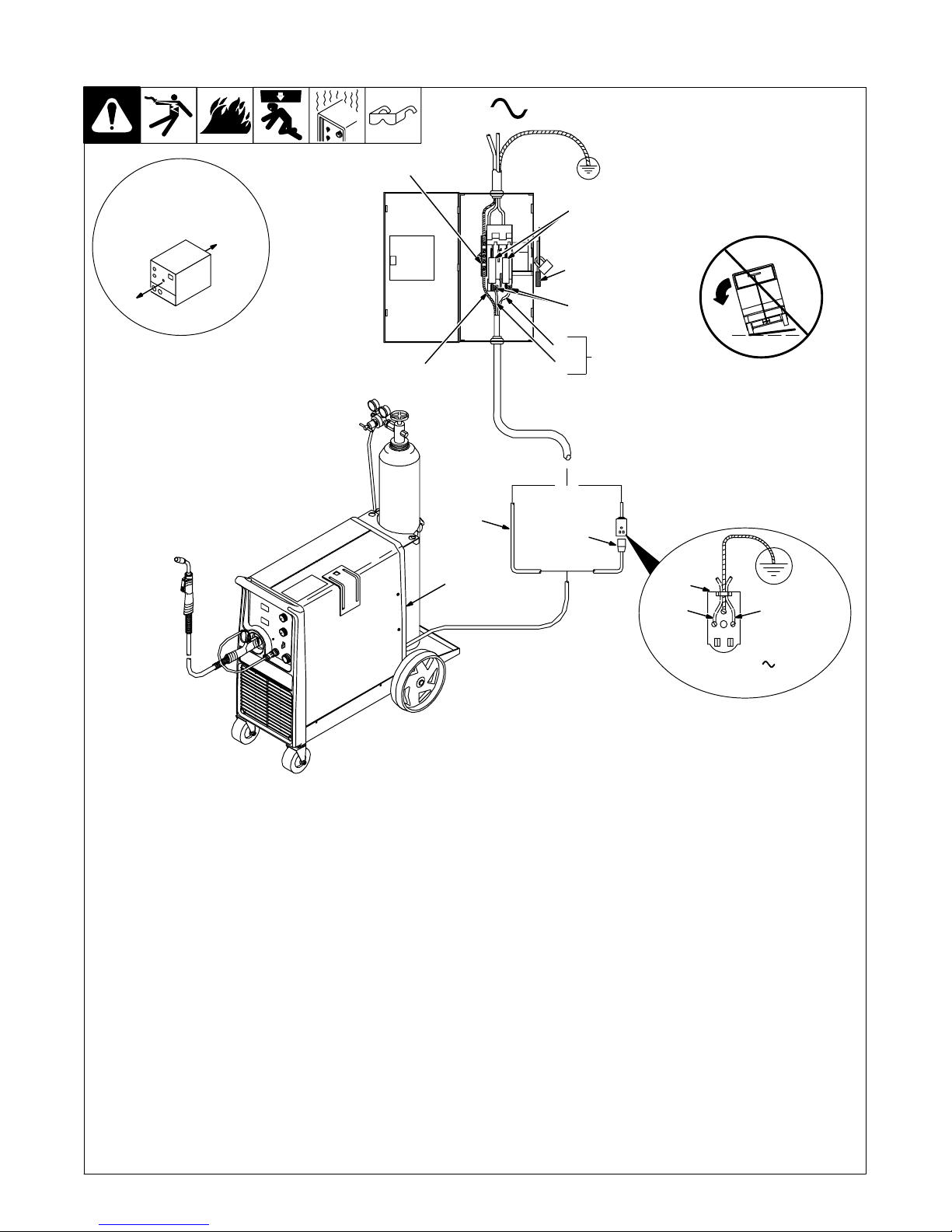
3-12. Selecting A Location And Connecting Input Power
1
18 in (457 mm) of
space for airflow
8
6
4
1
L1
=GND/PE Earth Ground
10
7
9
5
L2
2
Y Do not move or operate
unit where it could tip.
3
L1L2
Y Installation must meet all National
and Local Codes − have only qualified
persons make this installation.
Y Disconnect and lockout/tagout input
power before connecting input conductors from unit.
Y Always connect green or green/yel-
low conductor to supply grounding
terminal first, and never to a line terminal.
Y Special installation may be required
where gasoline or volatile liquids are
present − see NEC Article 511 or CEC
Section 20.
1 Rating Label
Supply correct input power.
2 Plug (NEMA Type 6-50P)
3 Receptacle
[NEMA Type 6-50R (Customer
Supplied)]
4 Input Power Cord.
Connect directly to line disconnect device if
hard wiring is required.
5 Black And White Input Conductor (L1
And L2)
6 Green Or Green/Yellow Grounding
Conductor
7 Disconnect Device (switch shown in
the OFF position)
8 Disconnect Device Grounding Terminal
230 VAC, 1
Ref. 802 477-B / 803 766-B
9 Disconnect Device Line Terminals
Connect green or green/yellow grounding
conductor to disconnect device grounding
terminal first.
Connect input conductors L1 and L2 to
disconnect device line terminals.
10 Over-Current Protection
Select type and size of over-current
protection using Section 3-11 (fused
disconnect switch shown).
Connect plug to receptacle if hard wiring
method is not used.
Close and secure door on disconnect device.
Remove lockout/tagout device, and place
switch in the On position.
TM-1326 Page 10 Millermatic 251
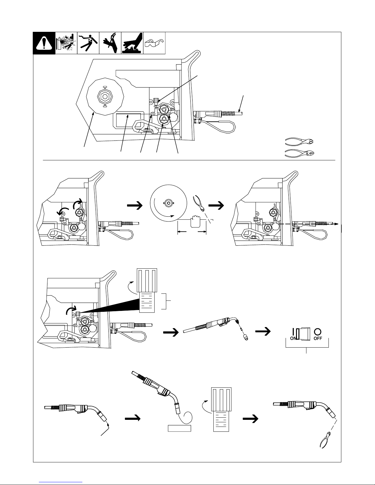
3-13. Threading Welding Wire
1 Wire Spool
2 Welding Wire
3 Inlet Wire Guide
4 Pressure Adjustment Knob
5 Drive Roll
4
6 Outlet Wire Guide
7 Gun Conduit Cable
Lay gun cable out straight.
7
Tools Needed:
35
621
. Hold wire tightly to keep it
from unraveling.
6 in
(150 mm)
Open pressure assembly. Pull and hold wire; cut off end. Push wire thru guides into gun;
Tighten
. Use pressure indicator
scale to set a desired
drive roll pressure.
1
2
3
4
Pressure
Indicator
Scale
continue to hold wire.
Close and tighten pressure
assembly, and let go of wire.
Press gun trigger until wire
comes out of gun. Reinstall
contact tip and nozzle
Remove gun nozzle and contact tip. Turn On.
Tighten
1
2
3
WOOD
4
Feed wire to check drive roll pressure.
Tighten knob enough to prevent slipping.
Cut off wire. Close
and latch door.
Ref. 802 064-D / S-0627-A
TM-1326 Page 11Millermatic 251
3-14. Using Gun/Cable Holder
2
4
1
1 Side Panel
2 Latch
3 Cable Holder
Press latch down to release and
open door.
3
4 Holster (2)
Wrap cable around cable holder,
and place gun nozzle into holster.
Ref. 802 726-A
TM-1326 Page 12 Millermatic 251

Notes
TM-1326 Page 13Millermatic 251
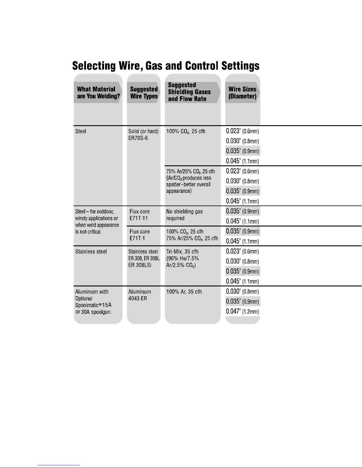
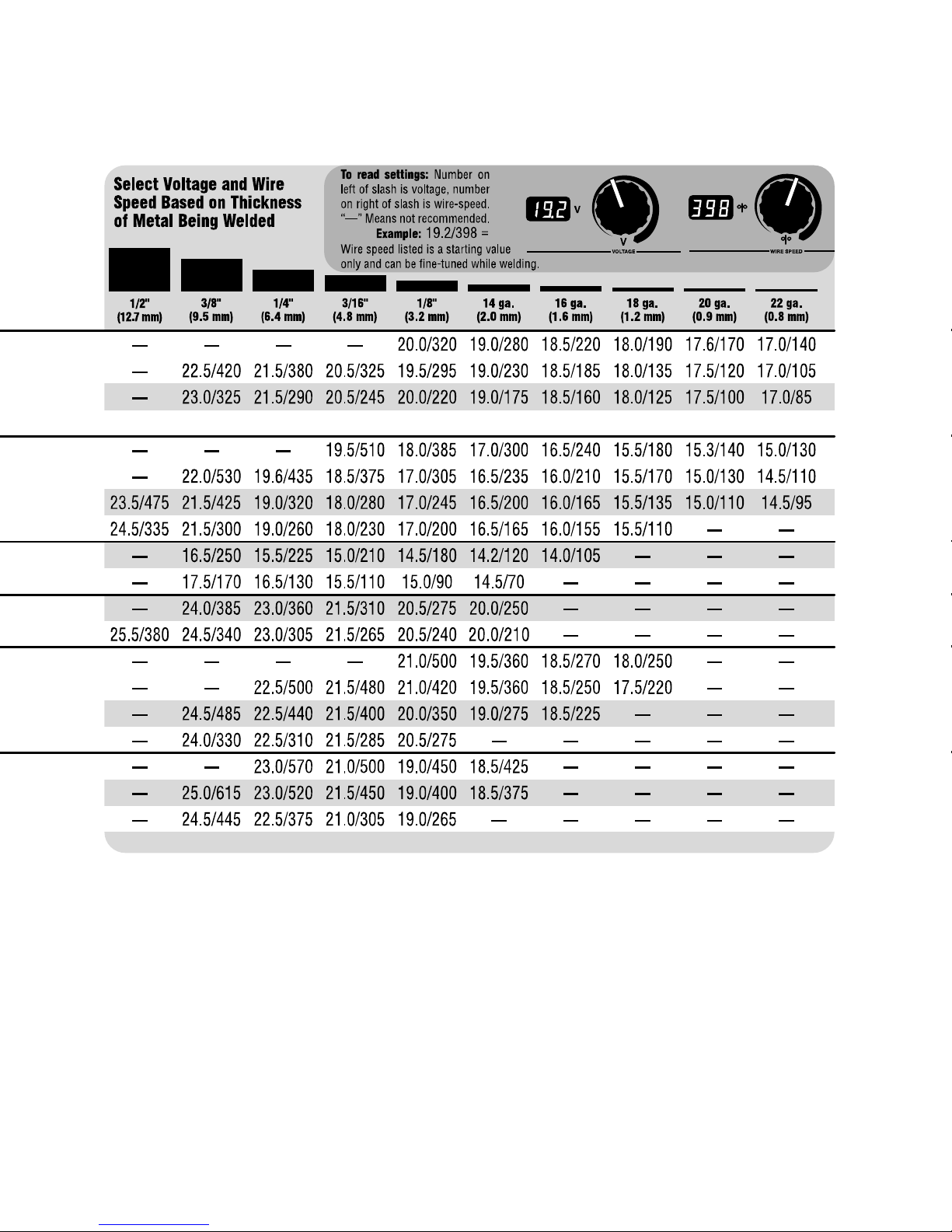
3-15. Weld Parameters
TM-1326 Page 14 Millermatic 251
201 202-A
TM-1326 Page 15Millermatic 251

SECTION 4 − OPERATION
4-1. Controls
4
5
3
. This unit has three automatic timers included in its operation to
help save contact tips, gas, and wire:
Tip Saver − Weld output shuts off if tip is shorted to work surface.
Safety shut-off − Weld output will shut off if no arc is detected within 3
seconds after gun trigger is depressed.
Jog mode − When loading a new roll of wire or if the gun trigger is
accidentally pressed, gas will shut off after 1 minute and wire will shut off
after 2 minutes saving wire and gas.
1 Voltage Control
Turn control clockwise to increase
voltage.
2 Wire Speed Control
Turn control clockwise to increase wire
feed speed.
JOG Mode
If the trigger on either gun is held for
more than 3 seconds without striking
1
an arc, the unit will automatically shut
off weld power (and shielding gas
output on MIG gun only), but will feed
wire continuously at the preset wire
feed speed (which may be faster or
slower than Run−in Speed) until trigger
is released.
Run−in Wire Feed Speed Settings
Run−in settings for the MIG and Spool
Guns are independently set and stored
in unit memory. The settings are in
percent of the welding wire feed speed
2
preset. Both settings are adjustable
from 25 to 150 percent.
MIG Gun Run−in is factory set at 100%
which is recommended for most wire
sizes and types.
Spool Gun Run−in is factory set at 50%
which is recommended for .030 & .035
wire. A Run−in setting of 25% is
recommended for .047 wire.
To check Run−in settings, start with
the power switch OFF. Press and hold
the MIG or Spool Gun Trigger while
turning the power switch ON. The unit
will power up with both the displays
reading 888 , then the voltage display
will read −−− and the wire feed display
will read the preset Run−in percentage
from memory for the gun selected. To
return to the weld mode without
making a change, simply release
trigger and pull the trigger again
momentarily (one second).
To change Run−in settings, start with
the power switch OFF. Press and hold
the MIG or Spool Gun Trigger while
turning the power switch ON. The unit
will power up with both the displays
reading 888 , then the voltage display
will read −−− and the wire feed display
will read the preset Run−in percentage
from memory for the gun selected. To
change the Run−in value, release the
trigger and turn the wire feed control
knob (or the wire feed adjustment knob
located on the bottom handle of the
spool gun) to the desired setting for the
selected gun. To return to weld mode
after the Run−in speed change, pull
the trigger momentarily (one second).
3 Power Switch
4 Voltmeter
5 Wire Feed Speed Meter
TM-1326 Page 16 Millermatic 251
Ref. 205 637
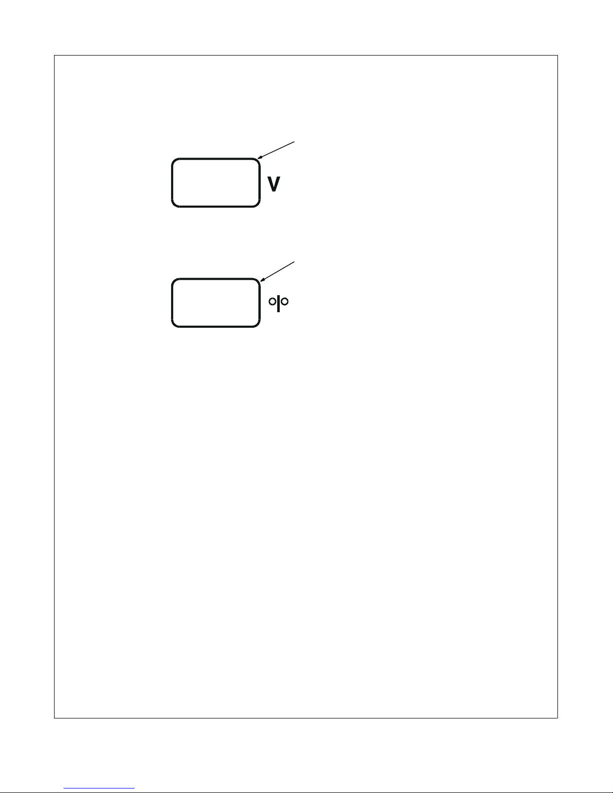
4-2. Voltmeter And Wire Feed Speed Meter Operation
1
2
1 Voltmeter
2 Wire Feed Speed Meter
Power Up Status
Both meters display 888 at unit power up.
After one second, preset values appear on
both meters. The MIG gun settings (not
spool gun) are always the default at initial
power up of the unit. If the power is reset to
quickly, characters other than 888 may ap-
pear. To reset, turn power off for at least 3
seconds, then turn power back on.
Welding Status
When either a MIG gun or spool gun trigger
is pressed and a welding arc is established,
the voltmeter displays actual weld voltage.
When the gun trigger is released and
welding arc extinguished, the voltmeter
displays the last actual voltage for 5
seconds and then returns to preset voltage.
If welding resumes before unit displays
preset voltage, actual welding voltage will
appear on the voltmeter.
The wire feed speed meter always displays
preset wire feed speed (IPM).
Gun Selection
The wire feed speed meter will display
preset wire feed speed (IPM) for the
appropriate gun selection either MIG or
spool gun. To preset desired wire feed
speed, connect desired gun, press gun
trigger for one second, and release trigger.
The meter preset will be retained by the
meter board until a different gun is
connected and preset is performed or the
unit is turned off and back on. The MIG gun
settings (not spool gun) are always the
default at initial power up of the unit.
Error Messages
Volt Meter Display (HL.P)
Wire Feed Speed Display (001)
HL.P 001 − Communication Lost between
Control Board PC1 and Display Board PC2
HL.P 002 − Unit over temperature, unit is in-
operative until temperature is reduced inside unit (see Section 6-1)
HL.P 003 − No Open Circuit Voltage (OCV)
detected when either trigger is pulled
HL.P 004 − Gun trigger was engaged for
approximately 2 minutes with no arc
detected, or weld wire is stuck causing a
direct short. If HL.P 004 occurs during
power up, see Section 6-1.
HL.P 005 − Wire feed malfunction. Check
wire feed delivery system (see Section
6-1).
See Section 6-1 for additional information
on all HL.P codes.
TM-1326 Page 17Millermatic 251
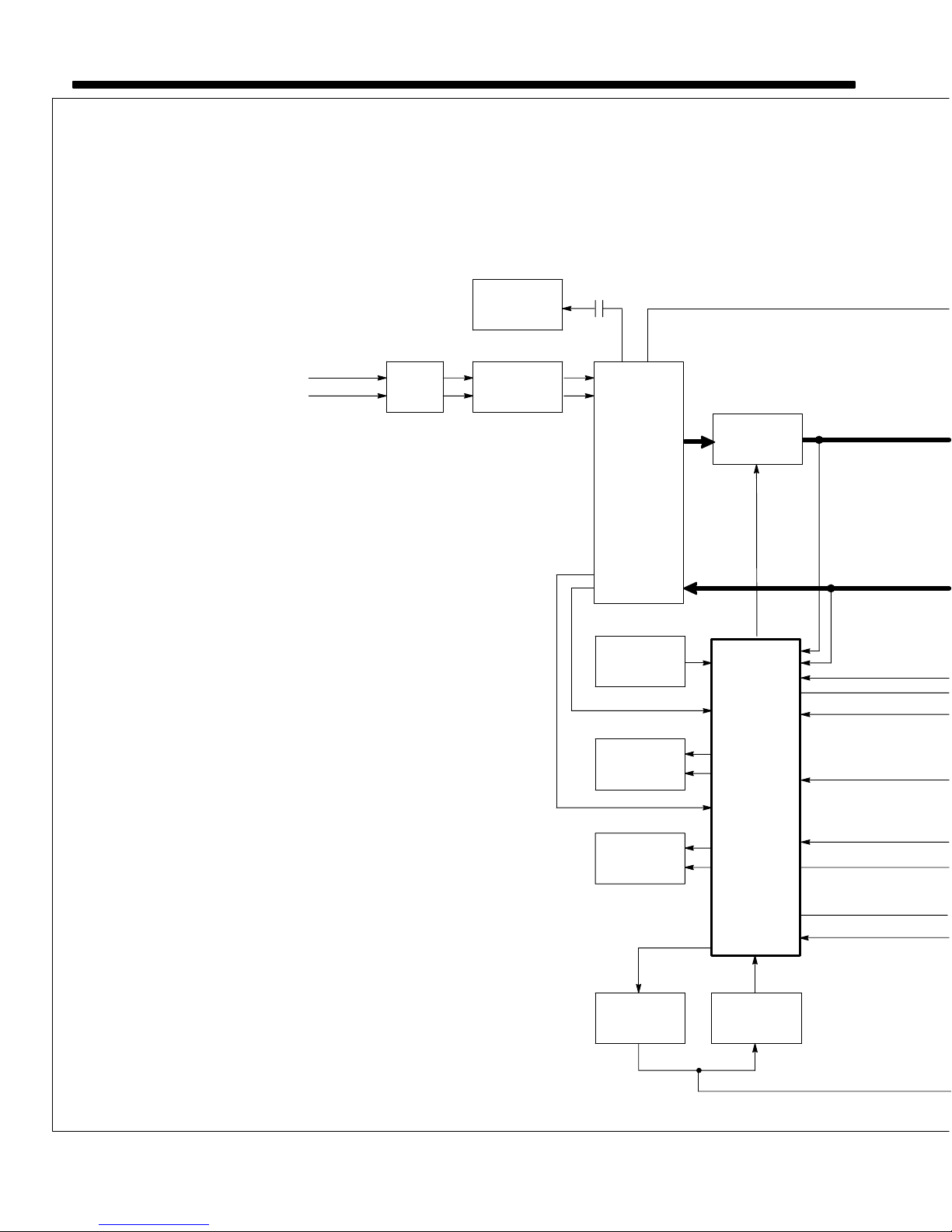
SECTION 5 − THEORY OF OPERATION
1 Power Switch S1
Turns unit on and off.
2 Input Terminal Board TE1
Provides means for operation on
different input voltages.
3 Main Transformer T1
Supplies power to weld output cir-
cuit, main control board PC1, other
control circuits, and fan motor FM.
4 Fan Motor FM
Controlled by thermistor, and fan
control relay CR1.
5 Rectifier SR1
SR1 Changes the ac output from T1
to full-wave rectified dc.
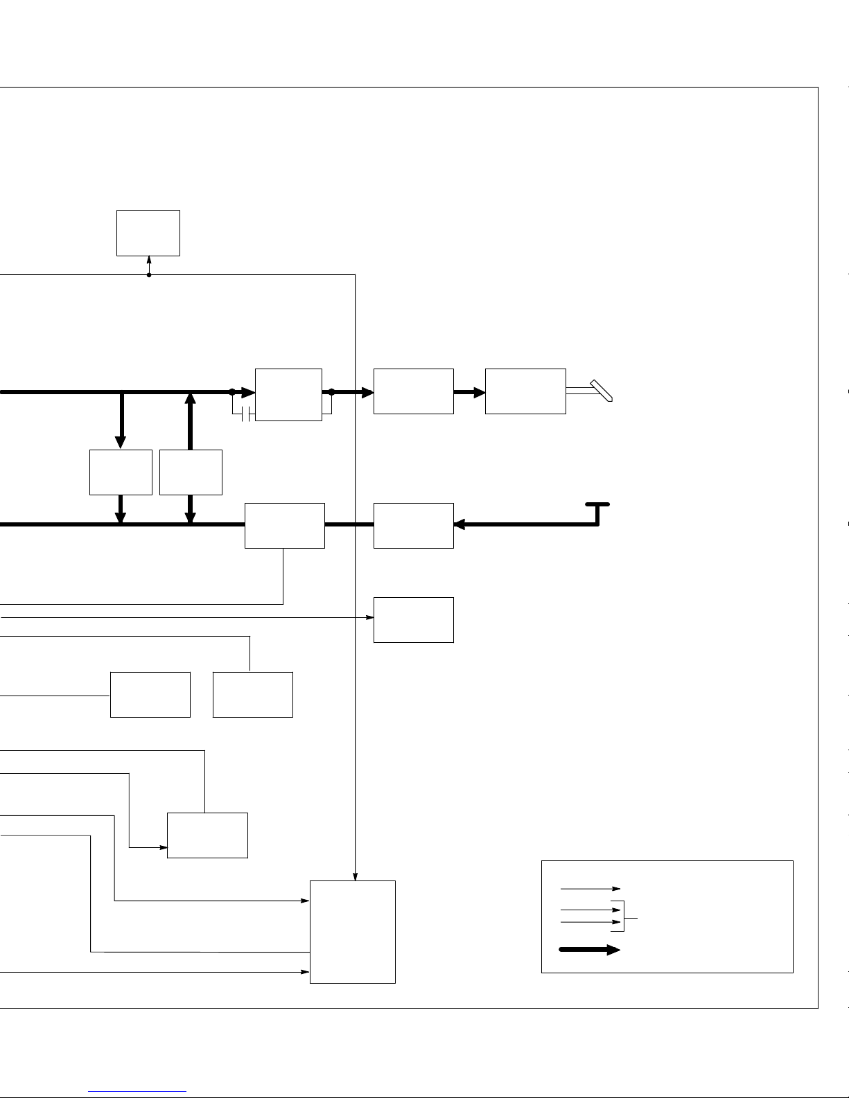
6 Capacitor Bank C5, Burden
Resistor R1
C5 filters the dc output voltage of
SR1; R1 discharges C5 when unit is
not triggered.
7 Stabilizer Z1
Smooths out current to positive (+)
output terminal on wire drive
assembly.
Start winding and contactor W
changes characteristic of stabilizer
Z1 during arc start operation.
8 Positive (+) And Negative (−)
Output Terminals
Provide weld output and allow
changing of output polarity.
9 Main Control Board PC1
Controls weld output by changing
the SCR gate pulses (conduction
times) after comparing voltage
feedback signal to selected voltage
signal.
Monitors unit temperature.
Controls wire speed by changing
the pulse width modulation signal
(wider or narrower pulses meaning
more or less voltage to motor) after
comparing motor speed feedback
voltage signal to selected voltage
signal.
Single-Phase
Line Input Power
A. Block Diagram
4
Fan Motor
FM
12 3
Power
Switch
S1
Input
Terminal
Board TE1
CR1
24 VAC
24 VAC
Main
Transformer
T1
10
Thermistor T
11
Gas Valve
GS1
Contactor W
24 VAC
5
Rectifier
SR1
9
Main
Control
Board PC1
SCR
Gate
Pulses
Voltage
Feedback
TM-1326 Page 18 Millermatic 251
12 13
Circuit
Breaker
CB1
Wire Drive
Motor PM
Pulse Width
Modulation
6
Burden
Resistor
4
Fan
Control
Relay CR1
R1
6
Capacitor
Bank C5
7
Stabilizer Z1
Contactor W
19
And Start
Winding
Reed
Relay
87
Positive (+)
Output
Terminal
8
Negative (−)
Output
Terminal
Wire
Drive
Assembly
Electrode
Work
10 Thermistor T
If unit overheats, PC1 disables unit
stopping all weld output.
11 Gas Valve GS1
Controlled by circuitry on main
control board PC1.
12 Circuit Breaker CB1
CB1 Protects wire drive motor PM
and spool gun motor circuits.
13 Wire Drive Motor PM
Feeds wire at a speed set by R3.
14 Wire Speed Control R3
Selects wire speed.
15 Voltage Control R2
Selects weld output voltage level.
16 Gun Trigger Receptacle RC1
Connects gun trigger circuit to
welding power source.
17 Receptacle RC7
Connects optional Spoolmatic 30A
welding gun.
18 Meter Board PC2
Voltmeter, Wire Feed Speed meter,
and HELP message displays.
19 Reed Relay
Senses weld current and changes
mode from start to weld.
14
Wire Speed
Control R3
16
Gun Trigger
Receptacle
RC1
15
Control R2
Voltage
17
Spool Gun
Receptacle
10-Pin
RC7
18
Meter
Board
PC2
AC Or DC Control Circuits
1φ Power
Weld Current Circuit
TM-1326 Page 19Millermatic 251
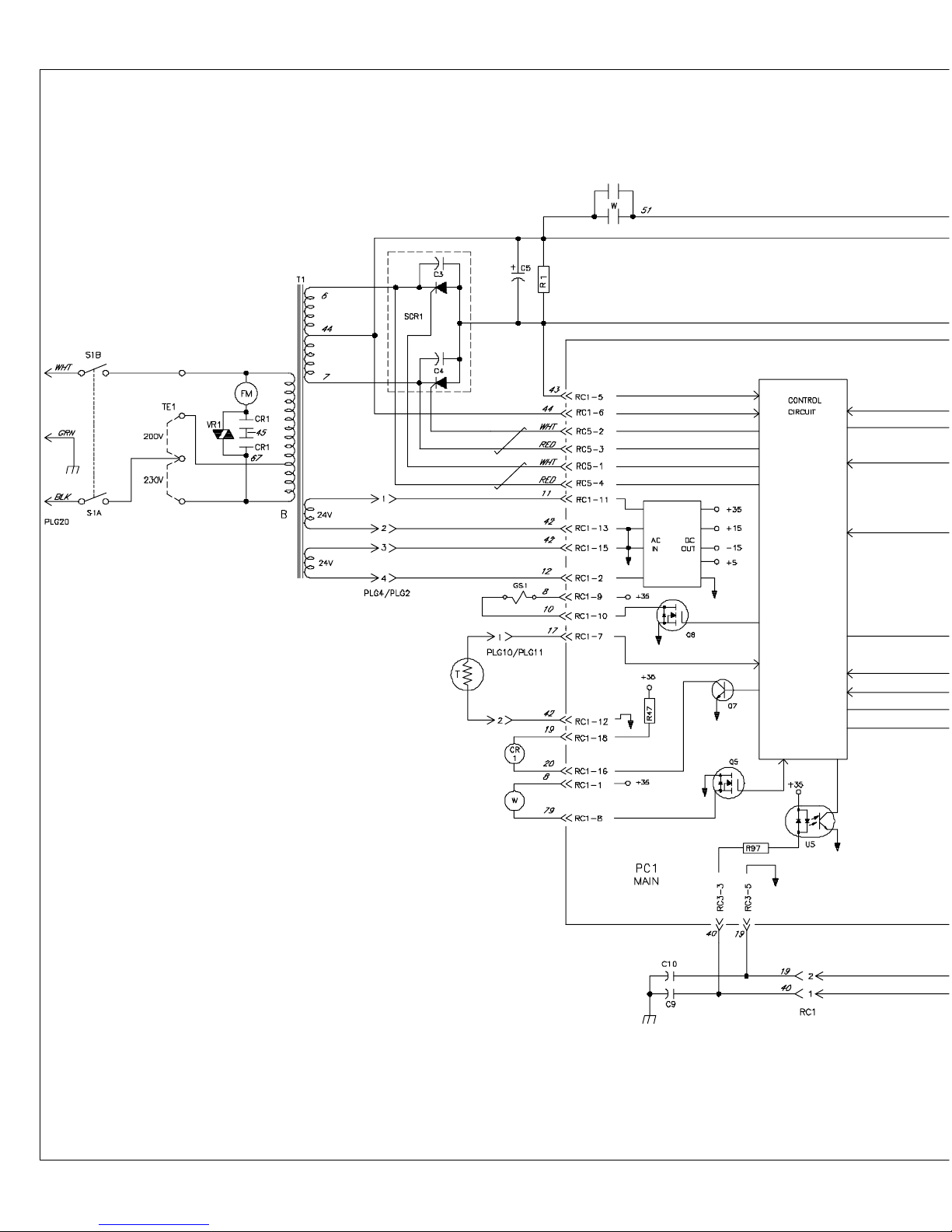
B. Basic Training Circuit
TM-1326 Page 20 Millermatic 251
 Loading...