

Miller Dynasty 280, Dynasty 210, Maxstar 210, Maxstar 280 Owner's Manual
OWNER’S MANUAL
OM-265 411D 2015−05
Read and follow the power source Owner’s Manual and labels carefully before installing, operating, or servicing unit.
Read the safety information at the beginning of the manual and in each section.
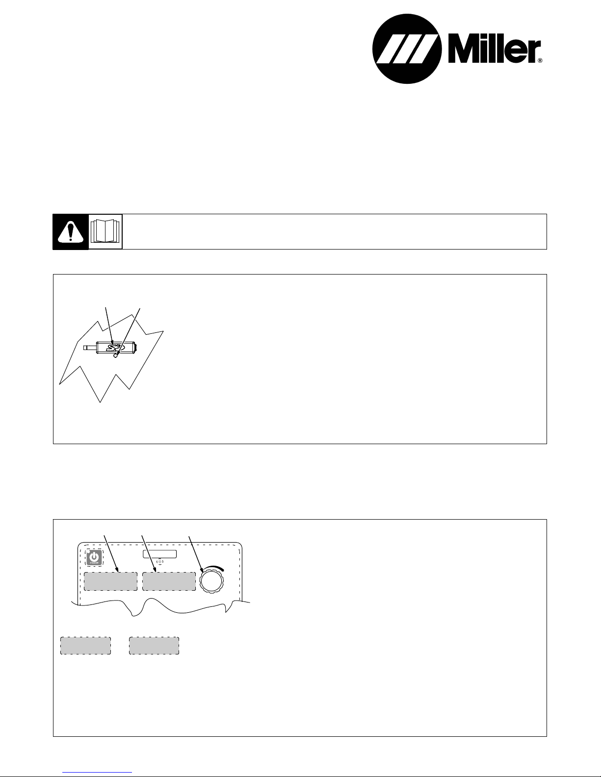
1-1. Software Expansion
Dynasty) − Maxstar) 280
Dynasty) − Maxstar) 210
Automation Expansion
. A software update is required to ensure proper
1
2
operation of all purchased feature expansions.
For instructions to download TIG Software updates, see PDF file F269272A on software expansion memory card.
Card Requirements:
. Purchased software expansion memory card
required.
1 Memory Card Port
2 Indicator LED
Enabling Software Expansion:
Insert card containing software expansion into port.
LED indicator blinks green while machine is reading
from or writing to the card. After successfully reading from or writing to the card, the LED switches
Automation Expansion − Enabling the automation software expansion configures Remote 14 socket I for valid arc and socket J for arc length control,
and the ability to configure socket E as an input for Output Enable (Weld Stop) in Dynastyand Maxstar 210 and 280 Models.
Additional Parts Required: Plug and pins required to connect to the Dynasty or Maxstar 210 and 280 Remote 14 receptacle can be obtained from
Miller Electric Mfg. Co. Parts Dept. :Order Part No. 141 162 − Housing Plugs + Pins (service kit), and install according to instructions provided with
the kit.
from blinking green to continuous green. The ma-
chine is now ready to use software expansion. Do
not remove card while LED is blinking green.
. Software expansion card must remain in mem-
ory card port to enable software expansion.
Disabling Software Expansion:
Remove the software expansion card from the
memory card port.
Troubleshooting:
Problem: Indicator LED is continuous red.
Remedy: Remove and reinsert card. If problem
continues, the card is bad. Contact Factory Authorized Service Center for a replacement card.
The memory card port uses an SD memory card.
The SD Logo is a trademark of the SD-3C LLC
Company.
1-2. Automation Remote 14-Socket E
1
TECH
2
MENU
3
. See ADVANCED MENU FUNCTIONS in the Dynasty/Maxstar
280’s Owner’s Manual or Dynasty/Maxtar 210 Owner’s Manual for
additional information on Accessing Tech Menu options.
The [14-E] option is before [MACH] [RSET], replacing the existing
[EXPC] option.
1 Parameter Display
2 Setting Display
3 Encoder
Rotate Encoder to adjust parameter setting.
14-E
[14-E] Remote - Remote14-Socket E input can be configured for the following:
[RMT] − Remote Controls − Select when using typical Miller remote amperage controls such as: RFCS - 14 HD Foot Control, or RCC -14
Remote Contactor and Current Control
[EXPC] − External Pulse Control − Select when it is desired to control machine amperage from an external source. A command voltage of
0−10 volts DC equals 0 (off) − maximum amperage.
[STOP] − Output Enable (weld stop) − Select to remotely stop the weld outside the normal weld cycle.
Remote 14 socket E connection to socket D must be maintained at all times to enable output. If connection is broken, output stops,
postflow begins, and AUTO STOP is displayed on the meters.
ORIGINAL INSTRUCTIONS − PRINTED IN USA © 2015 Miller Electric Mfg. Co.
RMT
1-3. Remote 14 Receptacle Information
Socket Socket Information
AJ
K
B
L
NH
C
M
D
F
E
15 VOLTS DC
OUTPUT
CONTACTOR
I
G
REMOTE
OUTPUT
CONTROL
Output
Signals
805 497-A
A Contactor control +15 volts DC, referenced to G.
B Contact closure to A completes 15 volts DC
contactor control circuit and enables output.
C Output to remote control; +10 volts DC output to
remote control.
D Remote control circuit common.
E 0 to +10 volts DC input command signal from
remote control.
*Reconfigurable as input for Output Enable (Weld
Stop) − used to remotely stop the weld outside the
normal welding cycle. Connection to the D socket
must be maintained at all times. If the connection
is broken, output stops, and Auto Stop is dis-
played.
F Current feedback; +1 volt DC per 100 amperes.
H Voltage feedback; +1 volt DC per 10 volts output.
I* Valid arc indication closed to socket G with valid
arc. Electrical specifications: open collector tran-
sistor (see Section 1-4 for connection example).
J* Arc length control lockout closed to socket G dur-
ing Initial and Final Amperage and Slope, and dur-
ing the background time of a <=10 Hz pulse wave-
form. Electrical specifications: open collector tran-
sistor (see Section 1-4 for connection example).
COMMON
CHASSIS
Serial
Communication
Bus
Sockets G and K are electrically isloated from each other.
G Return for all output signals: F, H, I, J and A.
K Chassis
L** Modbus Common (RS485 Common)
M** Modbus D1 (RS485 B+)
N** Modbus D0 (RS485 A-)
. If a remote hand control, like the RHC-14, is connected to the Remote 14 receptacle, some current value above min. must be set on the remote
control before the Panel or Remote contactor is turned on. Failure to do so will cause current to be controlled by the panel control, and the remote
hand control will not function.
*Available with optional Automation Expansion memory card.
**Available with optional Modbus Expansion memory card. Modbus serial communication provides access to all front panel parameters and
machine functionality. See Owner’s Manual 265415 for a list of Modbus registers. Modbus expansion also includes functionality of Automation
and AC Independent Amplitude (Dynasty only) Expansions.
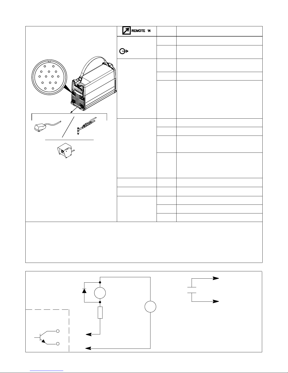
1-4. Simple Automation Application
Coil resistance plus R
should be chosen to
CR1
limit current to 75 mA
CR1
To User Equipment
+
User supplied power
up to 27 volts DC
Pin I, J: Collector
R
peak
−
Pin G: Emitter
OM−265 411 Page 2
 Loading...