

Miller Maxstar 152, Maxstar 175 Owner's Manual
June 1993 Form: OM-206C
Effective With Serial No. KD375312
OWNER’S
MANUAL
CC/DC Welding Power Source
For GTA W And SMAW Welding
120 A At 25 V Or 140 A At 25.6 V , 100% Duty Cycle
152 Model: Single-Phase; 175 Model: Three-Phase Input Power
Thermostat Protection Against Overheating
Touch Start For GTAW Welding
14-Pin Remote Control Receptacle
Read and follow these instructions and all
safety blocks carefully.
Have only trained and qualified persons
install, operate, or service this unit.
Call your distributor if you do not understand
the directions.
cover 8/92 – SA-145 666-B PRINTED IN USA
Maxstar 152 And 175
Give this manual to the operator.
For help, call your distributor
or: MILLER ELECTRIC Mfg. Co., P.O. Box
1079, Appleton, WI 54912 414-734-9821

From Miller to You
Thank you and congratulations on choosing Miller. Now you can get
the job done and get it done right. We know you don’t have time to do
it any other way.
That’s why when Niels Miller first started building arc welders in 1929,
he made sure his products offered long-lasting value and superior
quality. Like you, his customers couldn’t afford anything less. Miller
products had to be more than the best they could be. They had to be the
best you could buy.
Today, the people that build and sell Miller products continue the
tradition. They’re just as committed to providing equipment and service
that meets the high standards of quality and value established in 1929.
This Owner’s Manual is designed to help you get the most out of your
Miller products. Please take time to read the Safety precautions. They
will help you protect yourself against potential hazards on the worksite.
We’ve made installation and operation quick
and easy. With Miller you can count on years
of reliable service with proper maintenance.
And if for some reason the unit needs repair,
there’s a Troubleshooting section that will
help you figure out what the problem is. The
Miller is the first welding
equipment manufacturer in
the U.S.A. to be registered to
the ISO 9001 Quality System
Standard.
parts list will then help you to decide the
exact part you may need to fix the problem.
Warranty and service information for your
particular model are also provided.
Working as hard as you do
– every power source from
Miller is backed by the most
hassle-free warranty in the
business.
Miller Electric manufactures a full line
of welders and welding related equipment.
For information on other quality Miller
products, contact your local Miller distributor to receive the latest full
line catalog orindividual catalog sheets. To locate your nearest
distributor or service agency call 1-800-4-A-Miller, or visit us at
www.MillerWelds.com on the web.
Miller offers a Technical
Manual which provides
more detailed service and
parts information for your
unit. T o obtain a Technical
Manual, contact your local
distributor. Your distributor
can also supply you with
Welding Process Manuals
such as SMAW, GTAW,
GMAW, and GMA W-P.

EMF INFORMATION
NOTE
The following is a quotation from the General Conclusions Section of
the U.S. Congress, Office of Technology Assessment, Biological
Effects of Power Frequency Electric & Magnetic Fields –
Background Paper, OTA-BP-E-53 (Washington, DC: U.S.
Government Printing Office, May 1989): “. . . there is now a very large
volume of scientific findings based on experiments at the cellular
level and from studies with animals and people which clearly
establish that low frequency magnetic fields can interact with, and
produce changes in, biological systems. While most of this work is
of very high quality, the results are complex. Current scientific
understanding does not yet allow us to interpret the evidence in a
single coherent framework. Even more frustrating, it does not yet
allow us t o draw definite conclusions about questions of possible risk
or to offer clear science-based advice on strategies to minimize or
avoid potential risks.”
Considerations About Welding And The Effects Of Low Frequency Electric And
Magnetic Fields
To reduce magnetic fields in the workplace, use the following
procedures:
1. Keep cables close together by twisting or taping them.
2. Arrange cables to one side and away from the operator.
3. Do not coil or drape cables around the body.
4. Keep welding power source and cables as far away as practical.
5. Connect work clamp to workpiece as close to the weld as
possible.
About Pacemakers:
The above procedures are among those also normally
recommended for pacemaker wearers. Consult your doctor for
complete information.
TABLE OF CONTENTS
SECTION 1 – SAFETY INFORMATION 1. . . . . . . . . . . . . . . . . . . . . . . . . . . . . . . . . . . . . . . . . . . . . . . . . . . .
mod10.1 4/93
SECTION 2 – SPECIFICATIONS
2-1. Volt-Ampere Curves 2. . . . . . . . . . . . . . . . . . . . . . . . . . . . . . . . . . . . . . . . . . . . . . . . . . . . . . . . . . . .
2-2. Duty Cycle 2. . . . . . . . . . . . . . . . . . . . . . . . . . . . . . . . . . . . . . . . . . . . . . . . . . . . . . . . . . . . . . . . . . . .
SECTION 3 – INSTALLATION
3-1. Typical Process Connections 3. . . . . . . . . . . . . . . . . . . . . . . . . . . . . . . . . . . . . . . . . . . . . . . . . . . .
3-2. Selecting A Location And Moving Welding Power Source 3. . . . . . . . . . . . . . . . . . . . . . . . . . . .
3-3. Selecting And Preparing Weld Output Cables 4. . . . . . . . . . . . . . . . . . . . . . . . . . . . . . . . . . . . . .
3-4. Connecting To Weld Output Receptacles 5. . . . . . . . . . . . . . . . . . . . . . . . . . . . . . . . . . . . . . . . . .
3-5. Remote 14 Receptacle Information And Connections 5. . . . . . . . . . . . . . . . . . . . . . . . . . . . . . .
3-6. Connecting Input Power 6. . . . . . . . . . . . . . . . . . . . . . . . . . . . . . . . . . . . . . . . . . . . . . . . . . . . . . . .
SECTION 4 – OPERATION 8. . . . . . . . . . . . . . . . . . . . . . . . . . . . . . . . . . . . . . . . . . . . . . . . . . . . . . . . . . . . . . .
SECTION 5 – MAINTENANCE & TROUBLESHOOTING
5-1. Routine Maintenance 12. . . . . . . . . . . . . . . . . . . . . . . . . . . . . . . . . . . . . . . . . . . . . . . . . . . . . . . . . . .
5-2. Overload Protection 12. . . . . . . . . . . . . . . . . . . . . . . . . . . . . . . . . . . . . . . . . . . . . . . . . . . . . . . . . . . .
5-3. Measuring Input Capacitor Voltage 13. . . . . . . . . . . . . . . . . . . . . . . . . . . . . . . . . . . . . . . . . . . . . . .
5-4. Changing Amperage/Voltage Meter Hold Function 13. . . . . . . . . . . . . . . . . . . . . . . . . . . . . . . . . .
5-5. Troubleshooting 14. . . . . . . . . . . . . . . . . . . . . . . . . . . . . . . . . . . . . . . . . . . . . . . . . . . . . . . . . . . . . . .
SECTION 6 – ELECTRICAL DIAGRAMS 16. . . . . . . . . . . . . . . . . . . . . . . . . . . . . . . . . . . . . . . . . . . . . . . . . . .
SECTION 7 – TUNGSTEN ELECTRODE
7-1. Selecting Tungsten Electrode 22. . . . . . . . . . . . . . . . . . . . . . . . . . . . . . . . . . . . . . . . . . . . . . . . . . . .
7-2. Preparing Tungsten 23. . . . . . . . . . . . . . . . . . . . . . . . . . . . . . . . . . . . . . . . . . . . . . . . . . . . . . . . . . . .
SECTION 8 – PARTS LIST
Figure 8-1. Main Assembly 24. . . . . . . . . . . . . . . . . . . . . . . . . . . . . . . . . . . . . . . . . . . . . . . . . . . . . . . . . . . .
Figure 8-2. Module, Power & Diode (175 Model Illustrated) 27. . . . . . . . . . . . . . . . . . . . . . . . . . . . . . . .
OM-206C – 6/93

1
5
6
7
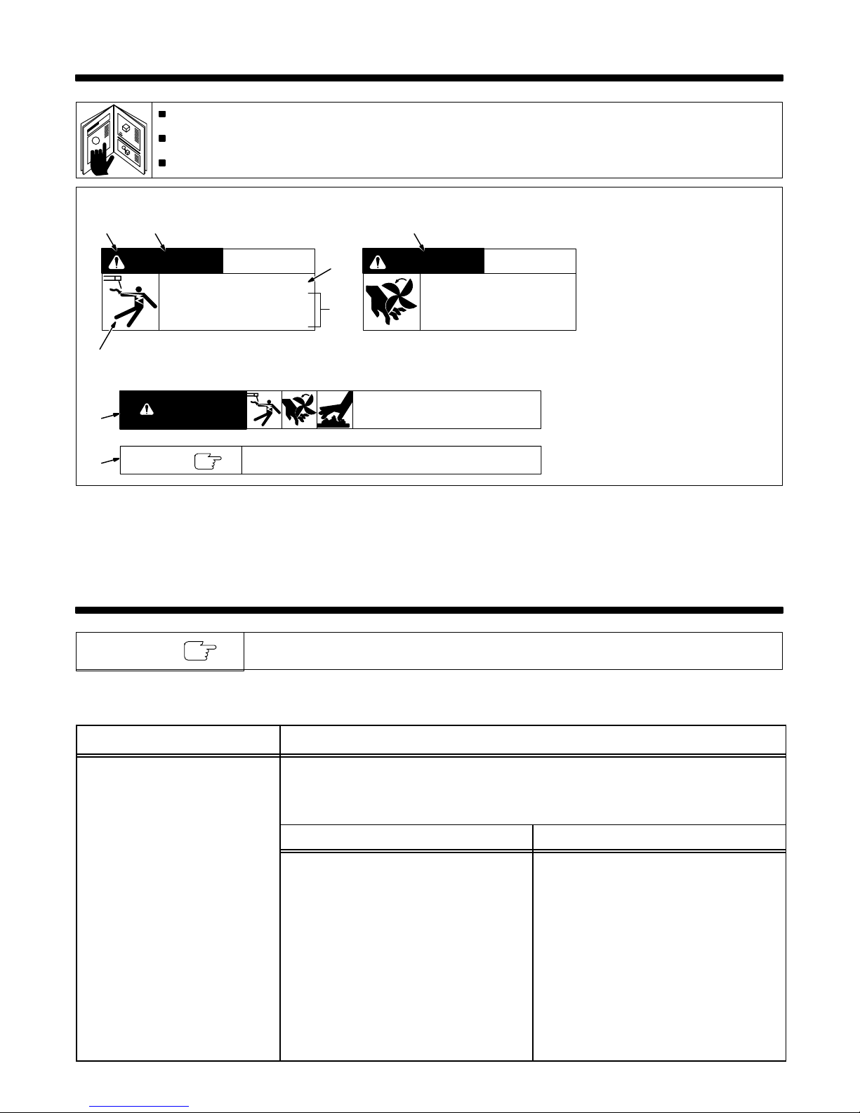
SECTION 1 – SAFETY INFORMATION
Read all safety messages throughout this manual.
Obey all safety messages to avoid injury.
Learn the meaning of WARNING and CAUTION.
2
WARNING
ELECTRIC SHOCK can kill.
• Do not touch live electrical parts.
• Disconnect input power before
installing or servicing.
WARNING
NOTE
Turn Off switch when using high frequency.
3
4
READ SAFETY BLOCKS at start of
Section 3-1 before proceeding.
2
CAUTION
MOVING PARTS can injure.
• Keep away from moving parts.
• Keep all panels and covers closed
when operating.
mod1.1 2/93
1 Safety Alert Symbol
2 Signal Word
WARNING means possible death
or serious injury can happen.
CAUTION means possible minor
injury or equipment damage can
happen.
3 Statement Of Hazard And
Result
4 Safety Instructions To Avoid
Hazard
5 Hazard Symbol (If Available)
6 Safety Banner
Read safety blocks for each sym-
bol shown.
7 NOTE
Special instructions for best oper-
ation – not related to safety.
Figure 1-1. Safety Information
SECTION 2 – SPECIFICATIONS
NOTE
Specification Description
Type Of Output Constant Current (CC), Direct Current (DC)
Welding Process Gas Tungsten Arc (GTAW), Shielded Metal Arc (SMAW) Welding
Options See Rear Cover
Rated Weld Output 120 Amperes, 25 Volts DC At 100% Duty Cycle
Type Of Input Power 230 Volts AC; 50/60 Hz; Single Phase 460 Volts AC; 50/60 Hz; Three-Phase
Input Amperes At Rated Output 25 A 12.5 A
KVA/KW Used At Rated Output 5.85 kVA/3.8 kW 9.56 kVA/5.26 kW
Amperage Range 1-150 A 1-175 A
Max. Open-Circuit Voltage 95 Volts DC 95 Volts DC
Overall Dimensions Length: 16-1/2 in (419 mm); Width: 9-1/2 in (241
Weight Net: 31 lb (14 kg); Ship: 36 lb (16 kg) Net: 39 lb (18 kg); Ship: 42 lb (19 kg)
Unless otherwise noted, the 175 model is shown throughout this manual.
Table 2-1. Welding Power Source
152 Models 175 Models
(See Section 2-2)
mm); Height: 8 in (203 mm)
140 Amperes, 26.5 Volts DC At 100% Duty Cycle
(See Section 2-2)
Length: 16-1/2 in (419 mm); Width: 9-1/2 in (241
mm); Height: 10 in (254 mm)
OM-206 Page 1
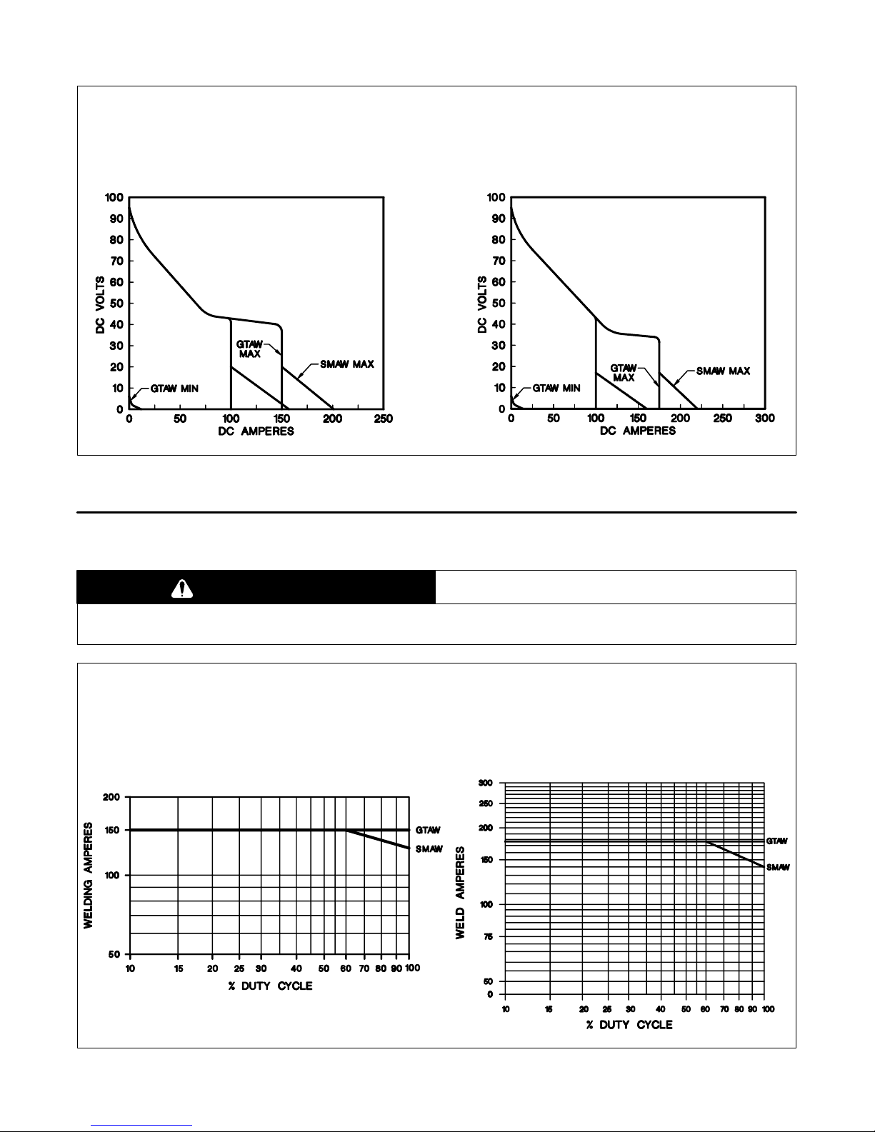
2-1. Volt-Ampere Curves
A. 152 Model B. 175 Model
The volt-ampere curves show the
minimum and maximum voltage
and amperage output capabilities
of the welding power source.
Curves of other settings fall between the curves shown.
ssb1.1 10/91 – SB-151 604 / SB-143 476-B
Figure 2-1. Volt-Ampere Curves
2-2. Duty Cycle
CAUTION
EXCEEDING DUTY CYCLE RATINGS will damage unit.
• Do not exceed indicated duty cycles.
A. 152 Model B. 175 Model
warn7.1 2/92
Duty cycle is how long the unit can
operate within a ten minute period
without causing overheating or
damage.
This unit is rated at 100% duty
cycle allowing continuous operation at rated load.
OM-206 Page 2
sb1.1 2/92 – SB-121 591-B / SB-144 507-B
Figure 2-2. Duty Cycle Chart
SECTION 3 – INSTALLATION
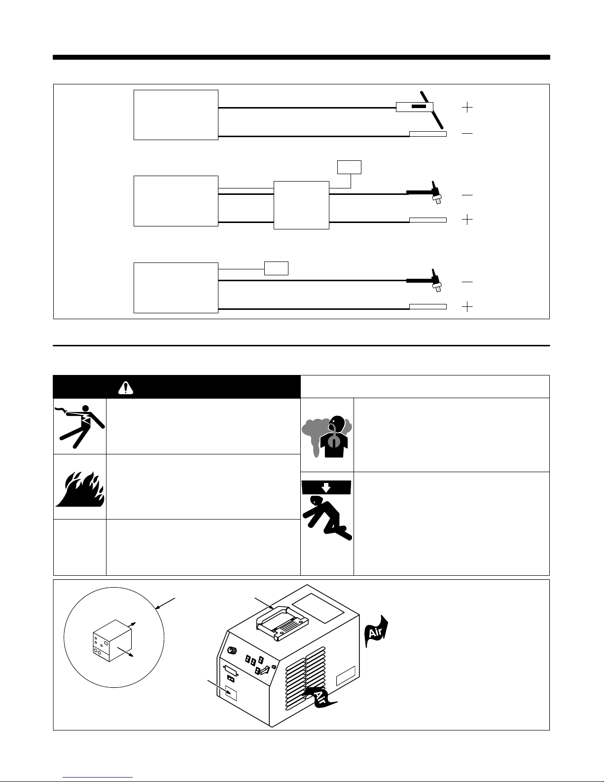
3-1. Typical Process Connections
Welding
Power Source
SMAW
Work
Remote Control
14 Pin
Welding
Power Source
Welding
Power Source
Pulse Control
14 Pin
GTAW
HF Unit
Scratch Start
Pulsed GTAW
Figure 3-1. Typical Process Connections
3-2. Selecting A Location And Moving Welding Power Source
WARNING
ELECTRIC SHOCK can kill.
• Do not touch live electrical parts.
• Disconnect input power conductors from
deenergized supply line BEFORE moving welding
power source.
FIRE OR EXPLOSION can result from
placing unit on, over, or near
combustible surfaces.
• Do not locate unit on, over, or near combustible
surfaces.
• Do not install unit near flammables.
BLOCKED AIRFLOW causes
overheating and possible damage to
unit.
• Do not block or filter airflow.
Warranty is void if any type of filter is used.
FUMES can be hazardous; LACK OF
FRESH AIR AND PROPER
VENTILATION can be harmful.
• Do not breathe welding fumes.
• Place unit only where there is a good fresh air
supply and proper ventilation.
FALLING EQUIPMENT can cause
serious personal injury and equipment
damage.
• Use handle to lift unit.
• Have person of adequate physical strength lift unit.
• Move unit with hand cart or similar device.
GTAW
Or
GTAW
Work
Work
swarn11.1* 2/92
1
Rear
Right
3
Figure 3-2. Location And Movement Of Welding Power Source
2
1 10 in (254 mm) Open Space
On Right Side And Rear Of
Unit For Good Airflow
2 Lifting Handle
Use handle to move unit.
3 Rating Label
Locate unit near correct input pow-
er supply.
Ref. SA-145 666-B
OM-206 Page 3
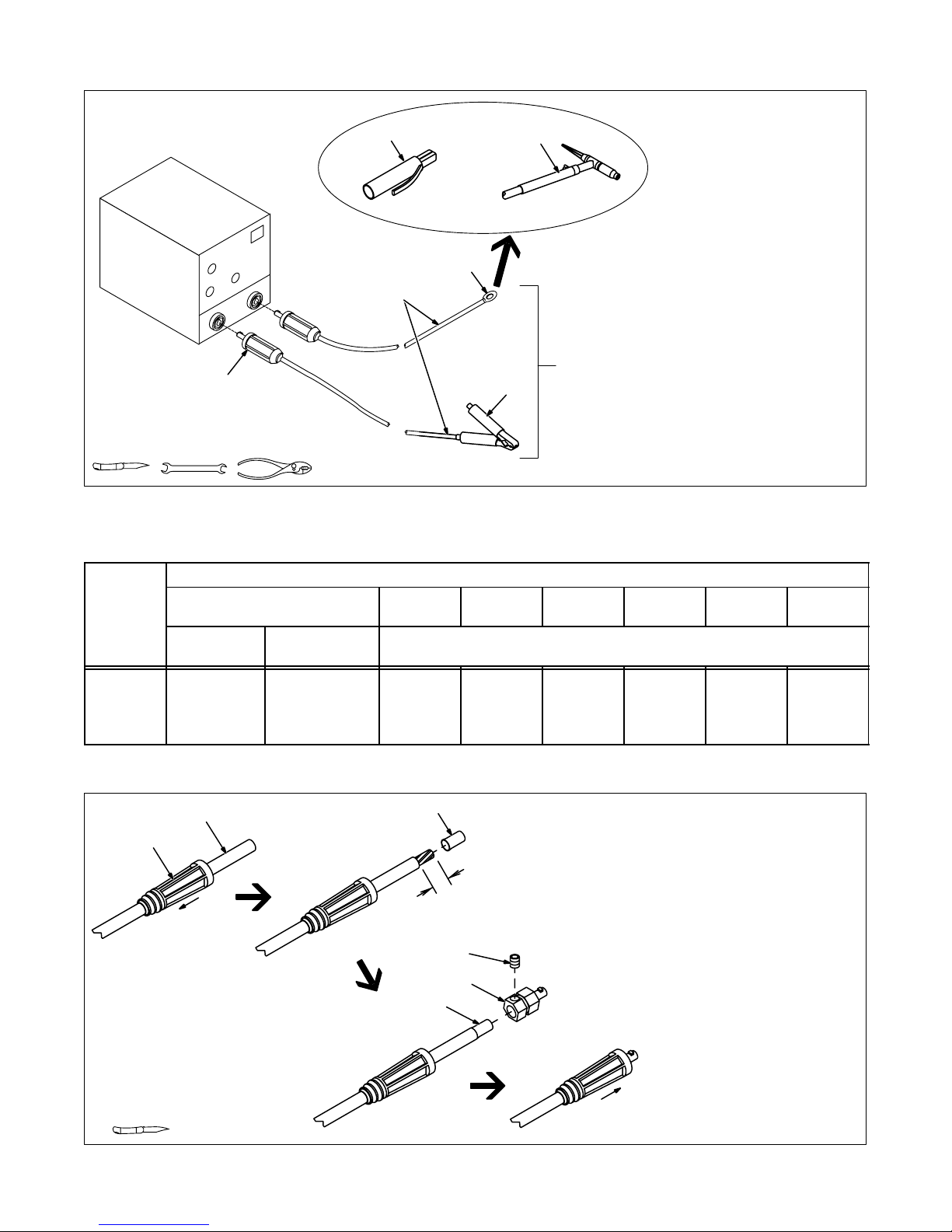
3-3. Selecting And Preparing Weld Output Cables
3
OR
2
1
10 ft (3 m)
Tools Needed:
6
10 ft (3 m)
Figure 3-3. Selecting And Preparing Weld Output Cables
5
4
For Example,
Total Cable
Length In Weld
Circuit = 20 ft (6 m)
1 Weld Output Cable
Determine total cable length in
weld circuit and maximum welding
amperes. Use Table 3-1 to select
proper cable size.
Use shortest cables possible.
Do not use damaged cables.
2 Terminal Lug
Use lugs of proper amperage
capacity and hole size for connecting to work clamp or electrode
holder.
3 Insulated Electrode Holder
4 GTAW Torch
Install according to manufacturer’s
instructions.
5 Work Clamp
Install onto work cable.
6 Dinse-Type Connector
Install onto weld cable as shown in
Figure 3-4.
sb6.2* 11/92 – S-0656
Table 3-1. Weld Cable Size*
Total Cable (Copper) Length In Weld Circuit Not Exceeding
100 ft (30 m) Or Less
Welding
Amperes
100 4 4 4 3 2 1 1/0 1/0
150 3 3 2 1 1/0 2/0 3/0 3/0
200 3 2 1 1/0 2/0 3/0 4/0 4/0
250 2 1 1/0 2/0 3/0 4/0 2-2/0 2-2/0
*Weld cable size (AWG) is based on either a 4 volts or less drop or a current density of not more than 300 circular mils per ampere. S-0007-C
2
10 To 60%
Duty Cycle
1
60 Thru 100%
Duty Cycle
150 ft
(45 m)
3
(26 mm)
200 ft
(60 m)
250 ft
(70 m)
300 ft
(90 m)
350 ft
(105 m)
400 ft
(120 m)
10 Thru 100% Duty Cycle
1 Weld Output Cable
2 Handle
3 Sleeve
Slide handle onto cable; strip cable
1 in
5
4
3
and install sleeve.
4 Connector Body
5 Setscrew
Insert cable with sleeve fully into
connector body, tighten setscrew,
and slide handle over connector.
If job requires cable larger than 3/0
AWG, use 2 ft (610 mm) or shorter
piece of 3/0 AWG cable for DinseType connector installation. Connect other end of short cable to the
4/0 or larger weld cable.
Tools Needed:
Figure 3-4. Dinse-Type Connector Assembly
OM-206 Page 4
ST-156 496
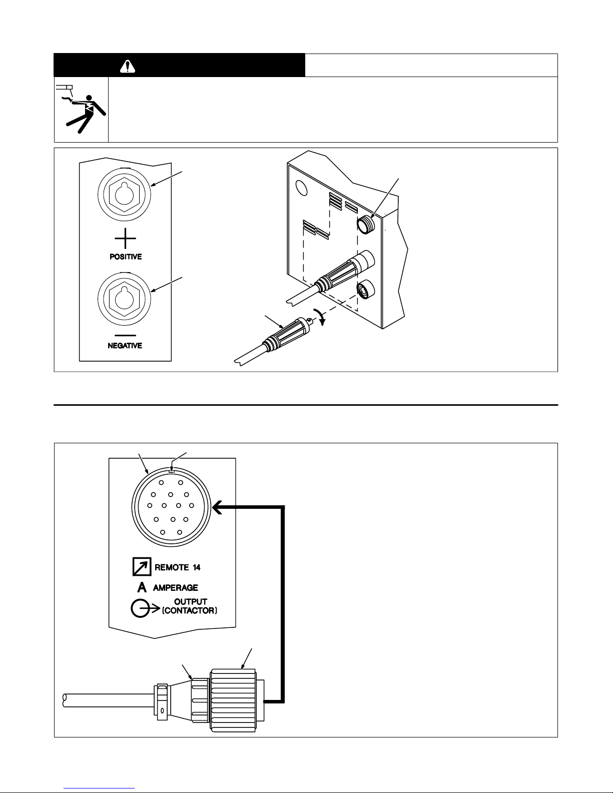
3-4. Connecting To Weld Output Receptacles
WARNING
ELECTRIC SHOCK can kill; ARCING can burn skin or damage electrical equipment.
• Do not touch live electrical parts.
• Turn Off welding power source before making any weld output connections.
• Do not change position of welding cable connectors while welding.
• Be sure connectors are secure in receptacles before welding.
1
2
3
swarn12.2 2/93
1 Positive (+) Weld Output
4
Receptacle
2 Negative (–) Weld Output
Receptacle
3 Connector
For Electrode Positive (DCEP),
connect work cable connector to
negative (–) receptacle and electrode holder cable connector to
positive (+) receptacle.
For Electrode Negative (DCEN),
reverse cable connections.
Align keyway, insert connector,
and turn clockwise.
4 Remote 14 Receptacle (see
Section 3-5).
Figure 3-5. Connecting To Weld Output Receptacles
3-5. Remote 14 Receptacle Information And Connections
1 2
AJ
K
B
L
C
D
Rear Panel
I
NH
M
G
F
E
3
Socket Information:
Remote Contactor
A +15 volts dc
B Contact closure to pin A completes +15 volts dc con-
tactor control circuit.
Remote Amperage/Voltage Control
C Command reference; +10 volts dc.
4
D Control circuit common.
E Input command signal (potentiometer wiper or 0 to
+10 volts dc).
K Chassis common.
The remaining sockets are not used.
Ref. SC-140 373 / Ref. ST-152 126
1 Remote 14 Receptacle RC7
2 Keyway
3 Plug
4 Threaded Collar
To connect to this receptacle, align
keyway, insert plug, and tighten
threaded collar.
sb7.1* 8/92 – Ref. SC-140 373 / Ref. S-0004-A / S-0750
Figure 3-6. Remote 14 Connections
OM-206 Page 5
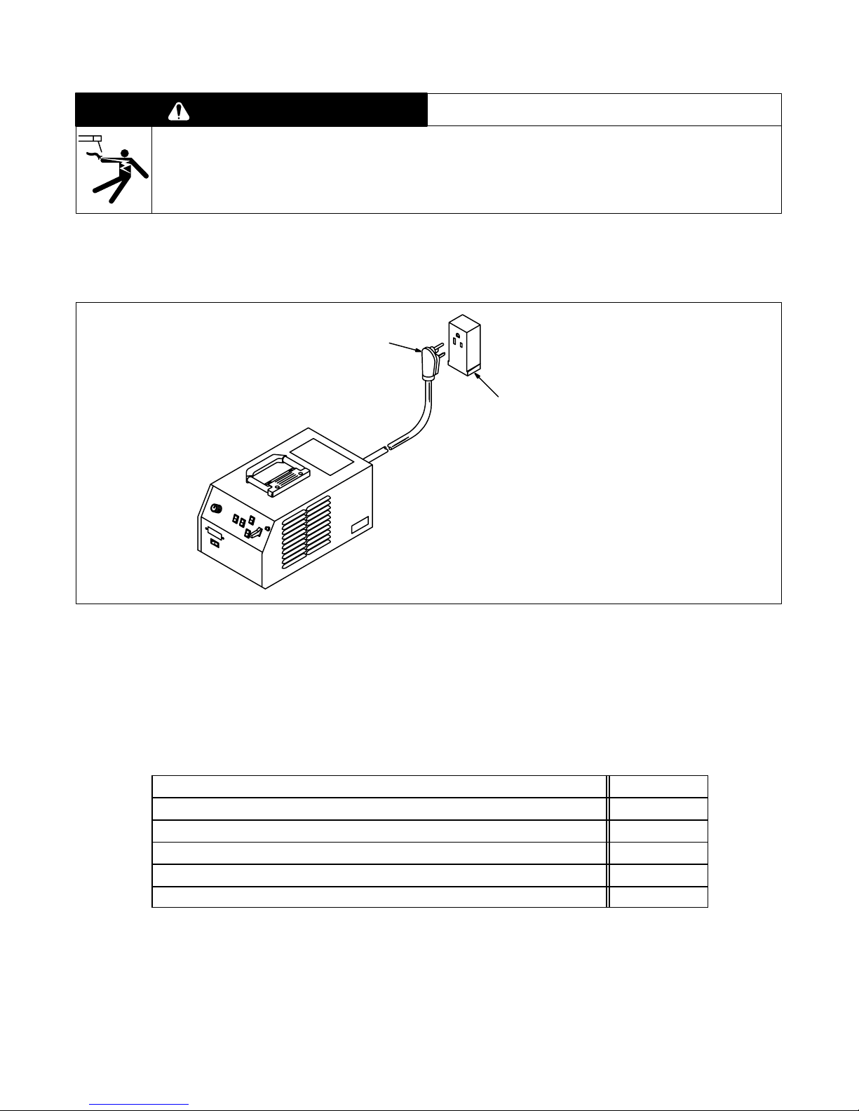
3-6. Connecting Input Power
WARNING
ELECTRIC SHOCK can kill.
• Do not touch live electrical parts.
• Turn Off welding power source, and disconnect input power before inspecting or installing.
• Have only qualified persons install unit.
• Installation must meet National Electrical Code and all other codes.
A. Connecting Input Power To 152 Models
swarn3.1 2/93
1 230 VAC Cord/Plug
1
2
2 230 VAC Grounded
Receptacle
An individual branch circuit capa-
ble of carrying 25 amperes, and
including overcurrent protection
such as fuses or circuit breaker is
required. Recommended standard
fuse or circuit breaker rating is 40
amperes.
Connect input power plug to proper
230 VAC receptacle.
Figure 3-7. Input Power Connections
B. Connecting Input Power To 175 Models
Table 3-2. Electrical Service Requirements For 175 Ampere Models*
Input Voltage
Input Amperes At Rated Output
Recommended Standard Fuse Or Circuit Breaker Rating In Amperes
Input Conductor Size In AWG/Kcmil
Max Input Conductor Length In Feet (Meters)
Grounding Conductor Size In AWG/Kcmil
*
These values are calculated from the 1990 edition of the National Electrical Code (NEC).
1 Recommended fuse or circuit breaker size is that closest to 150% of rated input amperage of the welding power
source. Article 630-12(a) of NEC allows fuse or circuit breaker sizing up to 200% of rated input amperage.
2 Input conductor size is for insulated copper wire with 75
conductors in a cable or raceway (Table 310-16 of NEC).
3 Maximum length is to prevent more than a 3% voltage drop between service entrance and input terminals of the
welding power source (Articles 210-19(a) and 215-2(b) of NEC).
4 The grounding conductor shall be colored or identified as specified in the NEC. Grounding conductor size for
copper wire is not required to be larger than input conductor (Article 250-95 of NEC).
OM-206 Page 6
ST-156 250
460
12
1
2
3
4
20
14
326 (99)
14
°C rating with not more than three single current-carrying
S-0092-F
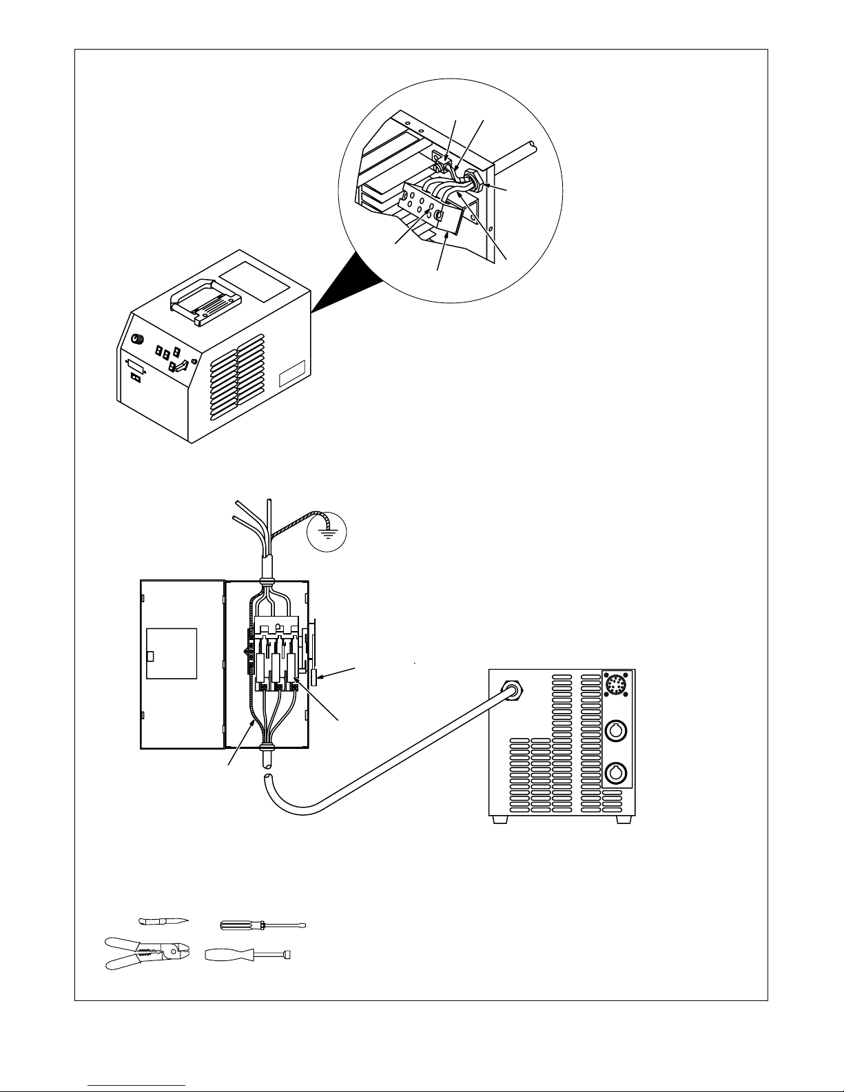
Have only qualified persons make
this installation.
Remove wrapper.
73
4
6
2
5
1 Line Disconnect Device Of
Proper Rating
2 Input Conductors
3 Grounding Conductor
Select size and length using
Table 3-2. Conductor rating must
comply with national, state, and local electrical codes.
Strip 3/8 in (10 mm) insulation off
all conductors.
4 Strain Relief Connector
Insert conductors through strain
relief.
5 Input Terminal Block
6 Line Terminals
7 Ground Terminal
Insert grounding conductor into
grounding terminal and tighten
screw.
Insert each input conductor into
proper screw terminal L1, L2, or L3
on terminal block and tighten
screws.
Install and connect grounding
conductor and input conductors in
conduit or equivalent to deenergized line disconnect device.
Be sure grounding conductor goes
to an earth ground.
Reinstall wrapper.
8 Overcurrent Protection
Select type and size using
Table 3-2. Install into deenergized
line disconnect device (fused
disconnect switch shown)
3
Tools Needed:
1
8
5/16 in
ssb2.4* 3/93 – ST-145 667-B / SA-145 666-B
Figure 3-8. Input Power Connections
OM-206 Page 7
 Loading...