

Page 1
OM-2242 208 580AA
2011−05
Processes
Stick (SMAW) Welding
TIG (GTAW) Welding
Description
Arc Welding Power Source
Maxstar 150 S, STL, And STH
With Auto-Linet
CE And Non-CE Models
ESPAÑOL FRANÇAIS ENGLISH
Visit our website at
www.MillerWelds.com
File: TIG (GTAW)
Page 2

From Miller to You
Thank you and congratulations on choosing Miller. Now you can get
the job done and get it done right. We know you don’t have time to do
it any other way.
That’s why when Niels Miller first started building arc welders in 1929,
he made sure his products offered long-lasting value and superior
quality. Like you, his customers couldn’t afford anything less. Miller
products had to be more than the best they could be. They had to be the
best you could buy.
Today, the people that build and sell Miller products continue the
tradition. They’re just as committed to providing equipment and service
that meets the high standards of quality and value established in 1929.
This Owner’s Manual is designed to help you get the most out of your
Miller products. Please take time to read the Safety precautions. They
will help you protect yourself against potential hazards on the worksite.
We’ve made installation and operation quick
and easy. With Miller you can count on years
of reliable service with proper maintenance.
And if for some reason the unit needs repair,
there’s a Troubleshooting section that will
help you figure out what the problem is. The
Miller is the first welding
equipment manufacturer in
the U.S.A. to be registered to
the ISO 9001 Quality System
Standard.
parts list will then help you to decide the
exact part you may need to fix the problem.
Warranty and service information for your
particular model are also provided.
Working as hard as you do
− every power source from
Miller is backed by the most
hassle-free warranty in the
business.
Miller Electric manufactures a full line
of welders and welding related equipment.
For information on other quality Miller
products, contact your local Miller distributor to receive the latest full
line catalog or individual specification sheets. To locate your nearest
distributor or service agency call 1-800-4-A-Miller, or visit us at
www.MillerWelds.com on the web.
Mil_Thank 2009−09
Page 3

TABLE OF CONTENTS
SECTION 1 − SAFETY PRECAUTIONS - READ BEFORE USING 1.................................
1-1. Symbol Usage 1.......................................................................
1-2. Arc Welding Hazards 1.................................................................
1-3. Additional Symbols For Installation, Operation, And Maintenance 3.............................
1-4. California Proposition 65 Warnings 4......................................................
1-5. Principal Safety Standards 4.............................................................
1-6. EMF Information 4.....................................................................
SECTION 2 − DEFINITIONS 5..................................................................
2-1. Warning Label Definitions 5..............................................................
2-2. Symbols And Definitions 6...............................................................
2-3. WEEE Label (For Products Sold Within The EU) 6..........................................
SECTION 3 − SPECIFICATIONS AND INSTALLATION 7...........................................
3-1. Important Information Regarding CE Products (Sold Within The EU) 7..........................
3-2. Serial Number And Rating Label Location 7................................................
3-3. Specifications 8........................................................................
3-4. Duty Cycle And Overheating 8...........................................................
3-5. Volt-Ampere Curves 9..................................................................
3-6. Remote 6 Receptacle Information (STL And STH Models Only) 9..............................
3-7. Electrical Service Guide For 230 VAC 10...................................................
3-9. Selecting A Location, And Connecting Input Power 11.........................................
3-10. Connecting 1-Phase Input Power For 230 VAC 12............................................
SECTION 4 − OPERATION 13...................................................................
4-1. Front Panel Controls And Gas Connection 13................................................
4-2. Process Selection (STL Model Only) 13....................................................
4-3. Process Selection (STH Model Only) 14....................................................
4-4. Lift-Arc And TIG Impulse Start Procedures 14...............................................
4-5. Set-Up Procedure For The TIG Process And Restoring Factory Default Settings (STH Model Only) 16
SECTION 5 − MAINTENANCE AND TROUBLESHOOTING 18.......................................
5-1. Routine Maintenance 18.................................................................
5-2. Overload Protection 18..................................................................
5-3. Troubleshooting 19......................................................................
SECTION 6 − ELECTRICAL DIAGRAM 20........................................................
SECTION 7 − PARTS LIST FOR S MODELS 22....................................................
SECTION 8 − PARTS LIST FOR STL MODELS 24.................................................
SECTION 9 − PARTS LIST FOR STH MODELS 26.................................................
OPTIONS AND ACCESSORIES
WARRANTY
Page 4

DECLARATION OF CONFORMITY
for European Community (CE marked) products.
MILLER Electric Mfg. Co., 1635 Spencer Street, Appleton, WI 54914 U.S.A. declares that the
product(s) identified in this declaration conform to the essential requirements and provisions of
the stated Council Directive(s) and Standard(s).
Product/Apparatus Identification:
Product
Stock Number
Maxstar 150 S 907351
Council Directives:
2006/95/EC Low Voltage
2004/108/EC Electromagnetic Compatibility
Standards:
IEC 609741: 2005 Arc Welding Equipment – Welding Power Sources
IEC 6097410: 2007 Arc Welding Equipment Electromagnetic Compatibility Requirements
EN 50445 Product family standard to demonstrate compliance of equipment for resistance welding, arc
welding and allied processes with the basic restrictions related to human exposure to electromagnetic fields
(0 Hz – 300Hz) BS EN 50445:2008.
US Signatory:
October 29, 2010
_____________________________________ _________________________________________
David A. Werba
MANAGER, PRODUCT DESIGN COMPLIANCE
241517C
Date of Declaration
Page 5

DECLARATION OF CONFORMITY
for European Community (CE marked) products.
MILLER Electric Mfg. Co., 1635 Spencer Street, Appleton, WI 54914 U.S.A. declares that the
product(s) identified in this declaration conform to the essential requirements and provisions of
the stated Council Directive(s) and Standard(s).
Product/Apparatus Identification:
Product Stock Number
Maxstar 150 STH 907352
Council Directives:
2006/95/EC Low Voltage
2004/108/EC Electromagnetic Compatibility
Standards:
IEC 609741: 2005 Arc Welding Equipment – Welding Power Sources
IEC 609743: 2007 Arc Welding Equipment – Arc Striking and Stabilizing Devices
IEC 6097410: 2007 Arc Welding Equipment – Electromagnetic Compatibility Requirements
EN 50445 Product family standard to demonstrate compliance of equipment for resistance welding, arc
welding and allied processes with the basic restrictions related to human exposure to electromagnetic fields
(0 Hz – 300Hz) BS EN 50445:2008.
US Signatory:
October 29, 2010
_____________________________________ ____________________________________
David A. Werba
MANAGER, PRODUCT DESIGN COMPLIANCE
Date of Declaration
241540C
Page 6

Page 7
SECTION 1 − SAFETY PRECAUTIONS - READ BEFORE USING
7
Protect yourself and others from injury — read and follow these precautions.
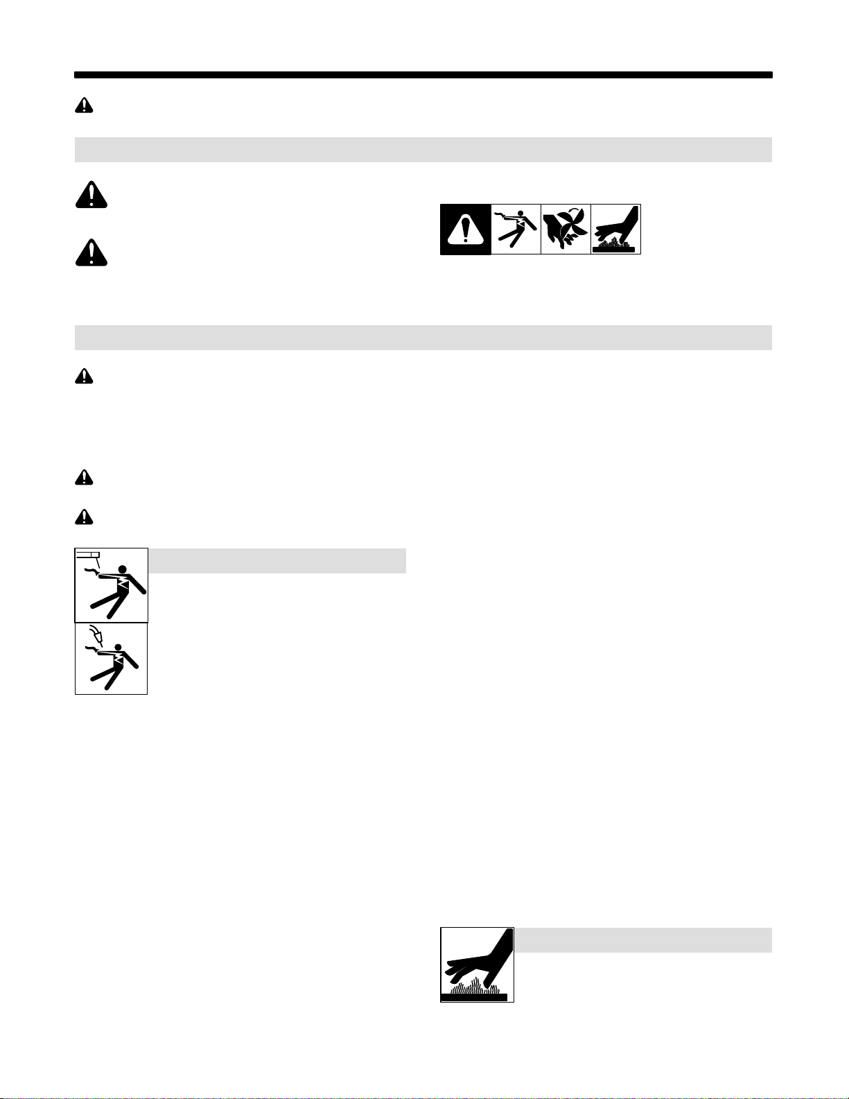
1-1. Symbol Usage
som 2011−01
DANGER! − Indicates a hazardous situation which, if
not avoided, will result in death or serious injury. The
possible hazards are shown in the adjoining symbols
or explained in the text.
Indicates a hazardous situation which, if not avoided,
could result in death or serious injury. The possible
hazards are shown in the adjoining symbols or explained in the text.
NOTICE − Indicates statements not related to personal injury.
1-2. Arc Welding Hazards
The symbols shown below are used throughout this manual
to call attention to and identify possible hazards. When you
see the symbol, watch out, and follow the related instructions
to avoid the hazard. The safety information given below is
only a summary of the more complete safety information
found in the Safety Standards listed in Section 1-5. Read and
follow all Safety Standards.
Only qualified persons should install, operate, maintain, and
repair this unit.
During operation, keep everybody, especially children, away.
ELECTRIC SHOCK can kill.
Touching live electrical parts can cause fatal shocks
or severe burns. The electrode and work circuit is
electrically live whenever the output is on. The input
power circuit and machine internal circuits are also
live when power is on. In semiautomatic or automatic
wire welding, the wire, wire reel, drive roll housing,
and all metal parts touching the welding wire are
electrically live. Incorrectly installed or improperly
grounded equipment is a hazard.
Do not touch live electrical parts.
Wear dry, hole-free insulating gloves and body protection.
Insulate yourself from work and ground using dry insulating mats
or covers big enough to prevent any physical contact with the work
or ground.
Do not use AC output in damp areas, if movement is confined, or if
there is a danger of falling.
Use AC output ONLY if required for the welding process.
If AC output is required, use remote output control if present on
unit.
Additional safety precautions are required when any of the follow-
ing electrically hazardous conditions are present: in damp
locations or while wearing wet clothing; on metal structures such
as floors, gratings, or scaffolds; when in cramped positions such
as sitting, kneeling, or lying; or when there is a high risk of unavoidable or accidental contact with the workpiece or ground. For these
conditions, use the following equipment in order presented: 1) a
semiautomatic DC constant voltage (wire) welder, 2) a DC manual
(stick) welder, or 3) an AC welder with reduced open-circuit voltage. In most situations, use of a DC, constant voltage wire welder
is recommended. And, do not work alone!
Disconnect input power or stop engine before installing or
servicing this equipment. Lockout/tagout input power according to
OSHA 29 CFR 1910.147 (see Safety Standards).
Properly install and ground this equipment according to its
Owner’s Manual and national, state, and local codes.
Indicates special instructions.
This group of symbols means Warning! Watch Out! ELECTRIC
SHOCK, MOVING PARTS, and HOT PARTS hazards. Consult symbols and related instructions below for necessary actions to avoid the
hazards.
Always verify the supply ground − check and be sure that input
power cord ground wire is properly connected to ground terminal in
disconnect box or that cord plug is connected to a properly
grounded receptacle outlet.
When making input connections, attach proper grounding conduc-
tor first − double-check connections.
Keep cords dry, free of oil and grease, and protected from hot metal
and sparks.
Frequently inspect input power cord for damage or bare wiring −
replace cord immediately if damaged − bare wiring can kill.
Turn off all equipment when not in use.
Do not use worn, damaged, undersized, or poorly spliced cables.
Do not drape cables over your body.
If earth grounding of the workpiece is required, ground it directly
with a separate cable.
Do not touch electrode if you are in contact with the work, ground,
or another electrode from a different machine.
Do not touch electrode holders connected to two welding ma-
chines at the same time since double open-circuit voltage will be
present.
Use only well-maintained equipment. Repair or replace damaged
parts at once. Maintain unit according to manual.
Wear a safety harness if working above floor level.
Keep all panels and covers securely in place.
Clamp work cable with good metal-to-metal contact to workpiece
or worktable as near the weld as practical.
Insulate work clamp when not connected to workpiece to prevent
contact with any metal object.
Do not connect more than one electrode or work cable to any
single weld output terminal.
SIGNIFICANT DC VOLTAGE exists in inverter welding power sources AFTER removal of input power.
Turn Off inverter, disconnect input power, and discharge input
capacitors according to instructions in Maintenance Section
before touching any parts.
HOT PARTS can burn.
Do not touch hot parts bare handed.
Allow cooling period before working on equip-
ment.
To handle hot parts, use proper tools and/or
wear heavy, insulated welding gloves and
clothing to prevent burns.
OM-2242 Page 1
Page 8
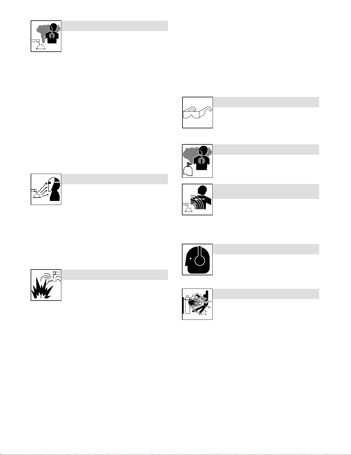
FUMES AND GASES can be hazardous.
)
Welding produces fumes and gases. Breathing
these fumes and gases can be hazardous to your
health.
Keep your head out of the fumes. Do not breathe the fumes.
If inside, ventilate the area and/or use local forced ventilation at the
arc to remove welding fumes and gases.
If ventilation is poor, wear an approved air-supplied respirator.
Read and understand the Material Safety Data Sheets (MSDSs)
and the manufacturer’s instructions for metals, consumables,
coatings, cleaners, and degreasers.
Work in a confined space only if it is well ventilated, or while
wearing an air-supplied respirator. Always have a trained watchperson nearby. Welding fumes and gases can displace air and
lower the oxygen level causing injury or death. Be sure the breathing air is safe.
Do not weld in locations near degreasing, cleaning, or spraying op-
erations. The heat and rays of the arc can react with vapors to form
highly toxic and irritating gases.
Do not weld on coated metals, such as galvanized, lead, or
cadmium plated steel, unless the coating is removed from the weld
area, the area is well ventilated, and while wearing an air-supplied
respirator. The coatings and any metals containing these elements
can give off toxic fumes if welded.
ARC RAYS can burn eyes and skin.
Remove stick electrode from holder or cut off welding wire at
contact tip when not in use.
Wear oil-free protective garments such as leather gloves, heavy
shirt, cuffless trousers, high shoes, and a cap.
Remove any combustibles, such as a butane lighter or matches,
from your person before doing any welding.
After completion of work, inspect area to ensure it is free of sparks,
glowing embers, and flames.
Use only correct fuses or circuit breakers. Do not oversize or by-
pass them.
Follow requirements in OSHA 1910.252 (a) (2) (iv) and NFPA 51B
for hot work and have a fire watcher and extinguisher nearby.
FLYING METAL or DIRT can injure eyes.
Welding, chipping, wire brushing, and grinding
cause sparks and flying metal. As welds cool,
they can throw off slag.
Wear approved safety glasses with side
shields even under your welding helmet.
BUILDUP OF GAS can injure or kill.
Shut off compressed gas supply when not in use.
Always ventilate confined spaces or use
approved air-supplied respirator.
Arc rays from the welding process produce intense
visible and invisible (ultraviolet and infrared) rays
that can burn eyes and skin. Sparks fly off from the
weld.
Wear an approved welding helmet fitted with a proper shade of
filter lenses to protect your face and eyes from arc rays and
sparks when welding or watching (see ANSI Z49.1 and Z87.1
listed in Safety Standards).
Wear approved safety glasses with side shields under your
helmet.
Use protective screens or barriers to protect others from flash,
glare and sparks; warn others not to watch the arc.
Wear protective clothing made from durable, flame-resistant
material (leather, heavy cotton, or wool) and foot protection.
WELDING can cause fire or explosion.
Welding on closed containers, such as tanks,
drums, or pipes, can cause them to blow up. Sparks
can fly off from the welding arc. The flying sparks, hot
burns. Accidental contact of electrode to metal objects can cause
sparks, explosion, overheating, or fire. Check and be sure the area is
safe before doing any welding.
Remove all flammables within 35 ft (10.7 m) of the welding arc. If
this is not possible, tightly cover them with approved covers.
Do not weld where flying sparks can strike flammable material.
Protect yourself and others from flying sparks and hot metal.
Be alert that welding sparks and hot materials from welding can
easily go through small cracks and openings to adjacent areas.
Watch for fire, and keep a fire extinguisher nearby.
Be aware that welding on a ceiling, floor, bulkhead, or partition can
cause fire on the hidden side.
Do not weld on closed containers such as tanks, drums, or pipes,
unless they are properly prepared according to AWS F4.1 (see
Safety Standards).
Do not weld where the atmosphere may contain flammable dust,
gas, or liquid vapors (such as gasoline).
Connect work cable to the work as close to the welding area as
practical to prevent welding current from traveling long, possibly
unknown paths and causing electric shock, sparks, and fire
hazards.
Do not use welder to thaw frozen pipes.
OM-2242 Page 2
workpiece, and hot equipment can cause fires and
ELECTRIC AND MAGNETIC FIELDS (EMF
can affect Implanted Medical Devices.
Wearers of Pacemakers and other Implanted
Medical Devices should keep away.
Implanted Medical Device wearers should consult their doctor
and the device manufacturer before going near arc welding, spot
welding, gouging, plasma arc cutting, or induction heating
operations.
NOISE can damage hearing.
Noise from some processes or equipment can
damage hearing.
Wear approved ear protection if noise level is
high.
CYLINDERS can explode if damaged.
Compressed gas cylinders contain gas under high
pressure. If damaged, a cylinder can explode. Since
gas cylinders are normally part of the welding
process, be sure to treat them carefully.
Protect compressed gas cylinders from excessive heat, mechani-
cal shocks, physical damage, slag, open flames, sparks, and arcs.
Install cylinders in an upright position by securing to a stationary
support or cylinder rack to prevent falling or tipping.
Keep cylinders away from any welding or other electrical circuits.
Never drape a welding torch over a gas cylinder.
Never allow a welding electrode to touch any cylinder.
Never weld on a pressurized cylinder − explosion will result.
Use only correct compressed gas cylinders, regulators, hoses,
and fittings designed for the specific application; maintain them
and associated parts in good condition.
Turn face away from valve outlet when opening cylinder valve.
Keep protective cap in place over valve except when cylinder is in
use or connected for use.
Use the right equipment, correct procedures, and sufficient num-
ber of persons to lift and move cylinders.
Read and follow instructions on compressed gas cylinders,
associated equipment, and Compressed Gas Association (CGA)
publication P-1 listed in Safety Standards.
Page 9
1-3. Additional Symbols For Installation, Operation, And Maintenance
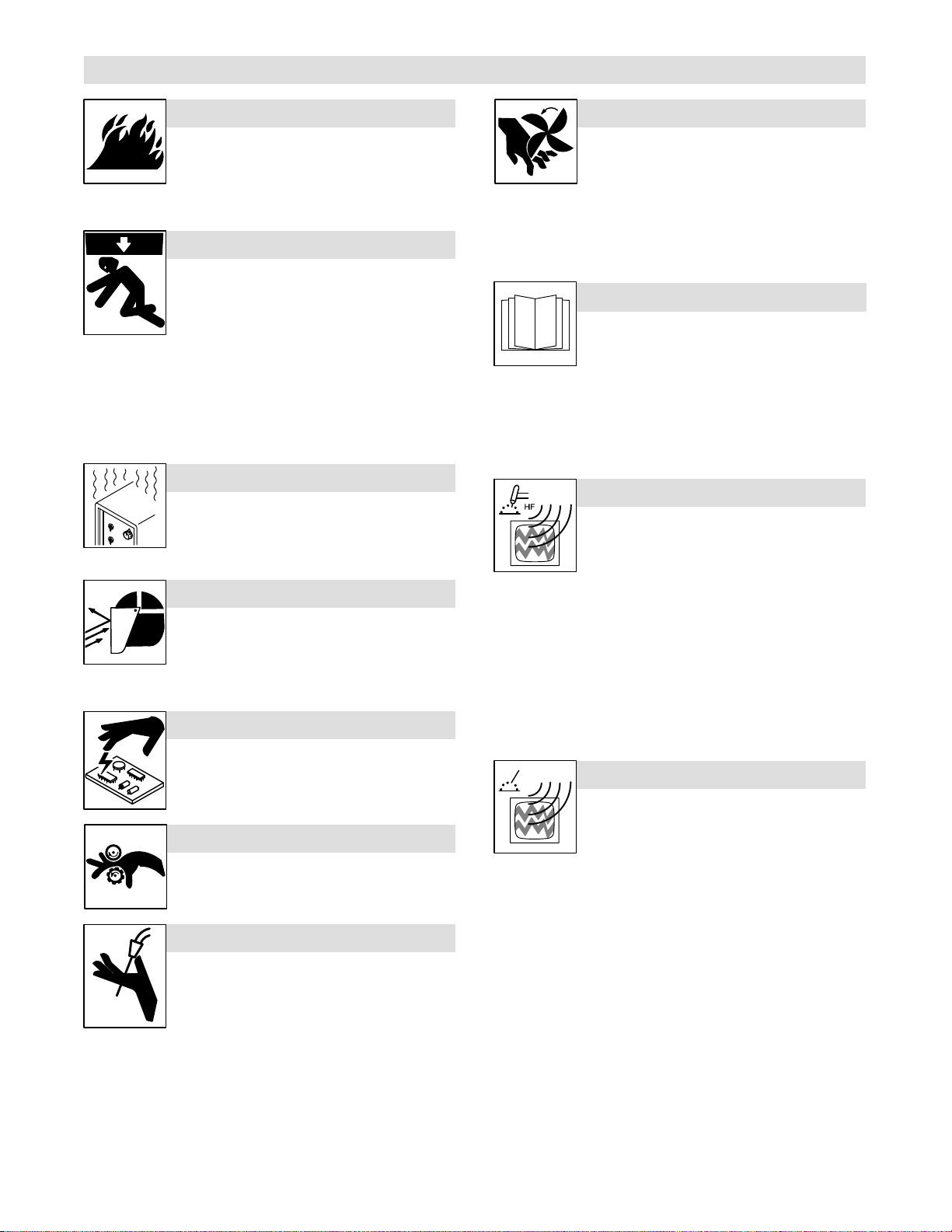
FIRE OR EXPLOSION hazard.
Do not install or place unit on, over, or near
combustible surfaces.
Do not install unit near flammables.
Do not overload building wiring − be sure power supply system is
properly sized, rated, and protected to handle this unit.
FALLING EQUIPMENT can injure.
Use lifting eye to lift unit only, NOT running
gear, gas cylinders, or any other accessories.
Use equipment of adequate capacity to lift and
support unit.
If using lift forks to move unit, be sure forks are long enough to
extend beyond opposite side of unit.
Keep equipment (cables and cords) away from moving vehicles
when working from an aerial location.
Follow the guidelines in the Applications Manual for the Revised
NIOSH Lifting Equation (Publication No. 94−110) when manually lifting heavy parts or equipment.
OVERUSE can cause OVERHEATING
Allow cooling period; follow rated duty cycle.
Reduce current or reduce duty cycle before
starting to weld again.
Do not block or filter airflow to unit.
FLYING SPARKS can injure.
Wear a face shield to protect eyes and face.
Shape tungsten electrode only on grinder with
proper guards in a safe location wearing proper
face, hand, and body protection.
Sparks can cause fires — keep flammables away.
STATIC (ESD) can damage PC boards.
Put on grounded wrist strap BEFORE handling
boards or parts.
Use proper static-proof bags and boxes to
store, move, or ship PC boards.
MOVING PARTS can injure.
Keep away from moving parts.
Keep away from pinch points such as drive
rolls.
WELDING WIRE can injure.
Do not press gun trigger until instructed to do
so.
Do not point gun toward any part of the body,
other people, or any metal when threading
welding wire.
MOVING PARTS can injure.
Keep away from moving parts such as fans.
Keep all doors, panels, covers, and guards
closed and securely in place.
Have only qualified persons remove doors, panels, covers, or
guards for maintenance and troubleshooting as necessary.
Reinstall doors, panels, covers, or guards when maintenance is
finished and before reconnecting input power.
READ INSTRUCTIONS.
Read and follow all labels and the Owner’s
Manual carefully before installing, operating, or
servicing unit. Read the safety information at
the beginning of the manual and in each
section.
Use only genuine replacement parts from the manufacturer.
Perform maintenance and service according to the Owner’s
Manuals, industry standards, and national, state, and local
codes.
H.F. RADIATION can cause interference.
High-frequency (H.F.) can interfere with radio
navigation, safety services, computers, and
communications equipment.
Have only qualified persons familiar with
electronic equipment perform this installation.
The user is responsible for having a qualified electrician prompt-
ly correct any interference problem resulting from the installation.
If notified by the FCC about interference, stop using the
equipment at once.
Have the installation regularly checked and maintained.
Keep high-frequency source doors and panels tightly shut, keep
spark gaps at correct setting, and use grounding and shielding to
minimize the possibility of interference.
ARC WELDING can cause interference.
Electromagnetic energy can interfere with
sensitive electronic equipment such as
computers and computer-driven equipment
such as robots.
Be sure all equipment in the welding area is
electromagnetically compatible.
To reduce possible interference, keep weld cables as short as
possible, close together, and down low, such as on the floor.
Locate welding operation 100 meters from any sensitive elec-
tronic equipment.
Be sure this welding machine is installed and grounded
according to this manual.
If interference still occurs, the user must take extra measures
such as moving the welding machine, using shielded cables,
using line filters, or shielding the work area.
OM-2242 Page 3
Page 10

1-4. California Proposition 65 Warnings
Welding or cutting equipment produces fumes or gases
which contain chemicals known to the State of California to
cause birth defects and, in some cases, cancer. (California
Health & Safety Code Section 25249.5 et seq.)
Battery posts, terminals and related accessories contain lead
and lead compounds, chemicals known to the State of
California to cause cancer and birth defects or other
reproductive harm. Wash hands after handling.
This product contains chemicals, including lead, known to
the state of California to cause cancer, birth defects, or other
reproductive harm. Wash hands after use.
1-5. Principal Safety Standards
Safety in Welding, Cutting, and Allied Processes, ANSI Standard Z49.1,
from Global Engineering Documents (phone: 1-877-413-5184, website:
www.global.ihs.com).
Safe Practices for the Preparation of Containers and Piping for Welding
and Cutting, American Welding Society Standard AWS F4.1, from Glob-
al Engineering Documents (phone: 1-877-413-5184, website:
www.global.ihs.com).
National Electrical Code, NFPA Standard 70, from National Fire Protection Association, Quincy, MA 02269 (phone: 1-800-344-3555, website:
www.nfpa.org and www. sparky.org).
Safe Handling of Compressed Gases in Cylinders, CGA Pamphlet P-1,
from Compressed Gas Association, 4221 Walney Road, 5th Floor,
Chantilly, VA 20151 (phone: 703-788-2700, website:www.cganet.com).
Safety in Welding, Cutting, and Allied Processes, CSA Standard
W117.2, from Canadian Standards Association, Standards Sales, 5060
Spectrum Way, Suite 100, Ontario, Canada L4W 5NS (phone:
800-463-6727, website: www.csa-international.org).
Safe Practice For Occupational And Educational Eye And Face Protection, ANSI Standard Z87.1, from American National Standards Institute,
For Gasoline Engines:
Engine exhaust contains chemicals known to the State of
California to cause cancer, birth defects, or other reproductive harm.
For Diesel Engines:
Diesel engine exhaust and some of its constituents are
known to the State of California to cause cancer, birth
defects, and other reproductive harm.
25 West 43rd Street, New York, NY 10036 (phone: 212-642-4900, website: www.ansi.org).
Standard for Fire Prevention During Welding, Cutting, and Other Hot
Work, NFPA Standard 51B, from National Fire Protection Association,
Quincy, MA 02269 (phone: 1-800-344-3555, website: www.nfpa.org.
OSHA, Occupational Safety and Health Standards for General Indus-
try, Title 29, Code of Federal Regulations (CFR), Part 1910, Subpart Q,
and Part 1926, Subpart J, from U.S. Government Printing Office, Superintendent of Documents, P.O. Box 371954, Pittsburgh, PA 15250-7954
(phone: 1-866-512-1800) (there are 10 OSHA Regional Offices—
phone for Region 5, Chicago, is 312-353-2220, website:
www.osha.gov).
U.S. Consumer Product Safety Commission (CPSC), 4330 East West
Highway, Bethesda, MD 20814 (phone: 301-504-7923, website:
www.cpsc.gov).
Applications Manual for the Revised NIOSH Lifting Equation, The National Institute for Occupational Safety and Health (NIOSH), 1600
Clifton Rd, Atlanta, GA 30333 (phone: 1-800-232-4636, website:
www.cdc.gov/NIOSH).
1-6. EMF Information
Electric current flowing through any conductor causes localized electric
and magnetic fields (EMF). Welding current creates an EMF field
around the welding circuit and welding equipment. EMF fields may interfere with some medical implants, e.g. pacemakers. Protective
measures for persons wearing medical implants have to be taken. For
example, access restrictions for passers−by or individual risk assessment for welders. All welders should use the following procedures in
order to minimize exposure to EMF fields from the welding circuit:
1. Keep cables close together by twisting or taping them, or using a
cable cover.
2. Do not place your body between welding cables. Arrange cables
to one side and away from the operator.
3. Do not coil or drape cables around your body.
4. Keep head and trunk as far away from the equipment in the
welding circuit as possible.
5. Connect work clamp to workpiece as close to the weld as
possible.
6. Do not work next to, sit or lean on the welding power source.
7. Do not weld whilst carrying the welding power source or wire
feeder.
About Implanted Medical Devices:
Implanted Medical Device wearers should consult their doctor and the
device manufacturer before performing or going near arc welding, spot
welding, gouging, plasma arc cutting, or induction heating operations.
If cleared by your doctor, then following the above procedures is recommended.
OM-2242 Page 4
Page 11
SECTION 2 − DEFINITIONS
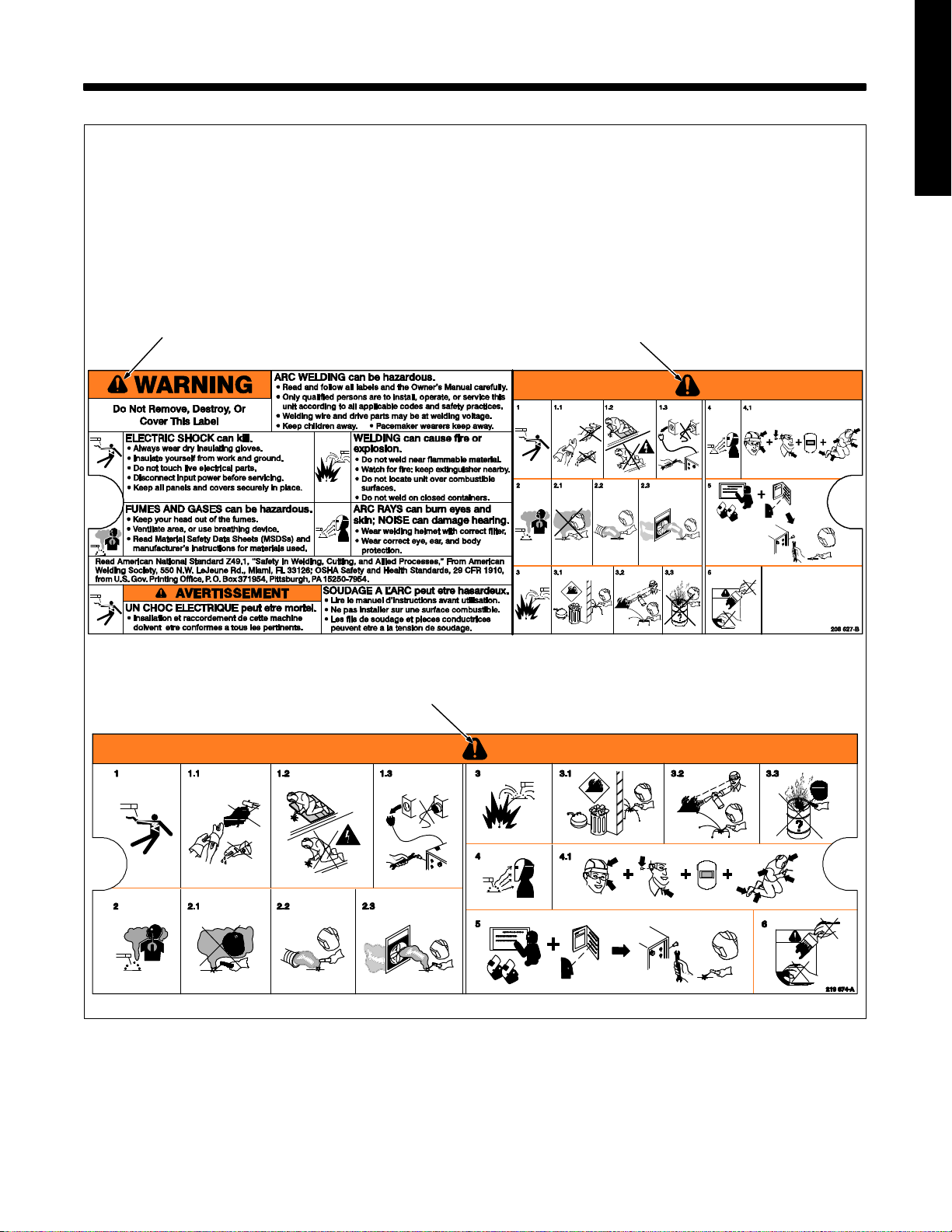
2-1. Warning Label Definitions
A. Warning! Watch Out! There are possible
hazards as shown by the symbols.
1 Electric shock from welding electrode or
wiring can kill.
1.1 Wear dry insulating gloves. Do not touch
electrode with bare hand. Do not wear wet
or damaged gloves.
1.2 Protect yourself from electric shock by
insulating yourself from work and ground.
1.3 Disconnect input plug or power before
working on machine.
2 Breathing welding fumes can be hazardous
to your health.
2.1 Keep your head out of the fumes.
2.2 Use forced ventilation or local exhaust to
remove the fumes.
2.3 Use ventilating fan to remove fumes.
3 Welding sparks can cause explosion or
fire.
3.1 Keep flammables away from welding. Do
not weld near flammables.
3.2 Welding sparks can cause fires. Have a
fire extinguisher nearby, and have a
watchperson ready to use it.
3.3 Do not weld on drums or any closed
containers.
4 Arc rays can burn eyes and injure skin.
4.1 Wear hat and safety glasses. Use ear
protection and button shirt collar. Use
welding helmet with correct shade of filter.
Wear complete body protection.
5 Become trained and read the instructions
before working on the machine or welding.
6 Do not remove or paint over (cover) the
label.
ENGLISH
A
A
A
OM-2242 Page 5
Page 12
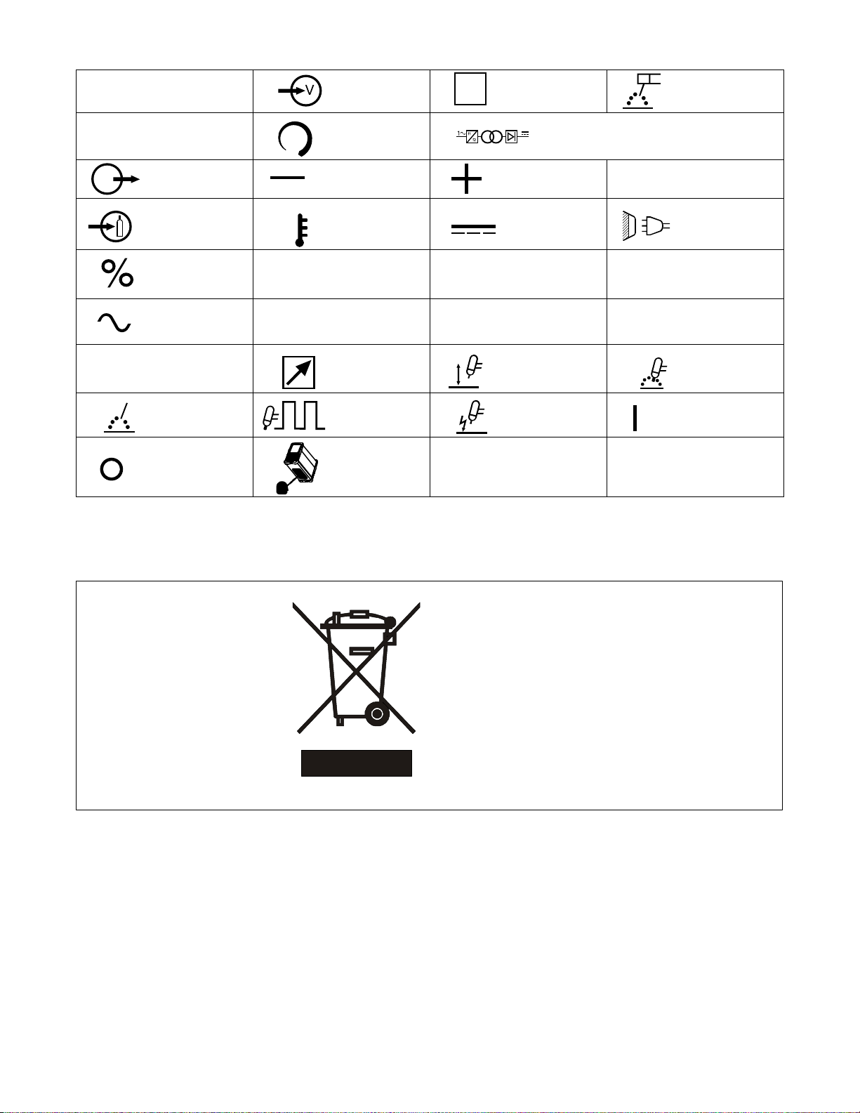
2-2. Symbols And Definitions
A
Amperes Voltage Input
S
Suitable For Areas
Of Increased
Shock Hazard
Shielded Metal Arc
Welding (SMAW)
I
1eff
V
Volts
Output Negative Positive
Gas Input High Temperature Direct Current Line Connection
Percent
Alternating
Current
Maximum Effective
Supply Current
Process TIG (GTAW) Pulse
Off
X
U
Increase/Decrease
Of Quantity
Duty Cycle
Rated No Load
Voltage (Average) I
0
Remote
Look under unit for
label
U
1
1max
Primary Voltage
Rated Maximum
Supply Current
Lift-Arc Start
(GTAW)
HF Impulse Start-
ing (GTAW)
Single Phase Static Frequency
Converter-Transformer-Rectifier
Hz
Conventional Load
U
I
2
2
Voltage
Rated Welding
Current
Gas Tungsten Arc
Welding (GTAW)
Hertz
On
2-3. WEEE Label (For Products Sold Within The EU)
Do not discard product (where applicable) with general waste.
Reuse or recycle Waste Electrical
and Electronic Equipment (WEEE)
by disposing at a designated collection facility.
Contact your local recycling office
or your local distributor for further
information.
OM-2242 Page 6
Page 13

SECTION 3 − SPECIFICATIONS AND INSTALLATION
3-1. Important Information Regarding CE Products (Sold Within The EU)
A. Information On Electromagnetic Fields (EMF)
! This equipment shall not be used by the general public as the EMF limits for the general public might be exceeded during welding.
This equipment is built in accordance with EN 60974−1 and is intended to be used only in an occupational environment (where the general public
access is prohibited or regulated in such a way as to be similar to occupational use) by an expert or an instructed person.
Wire feeders and ancillary equipment (such as torches, liquid cooling systems and arc striking and stabilizing devices) as part of the welding
circuit may not be a major contributor to the EMF. See the Owner’s Manuals for all components of the welding circuit for additional EMF exposure
information.
The EMF assessment on this equipment was conducted at 0.5 meter.
At a distance of 1 meter the EMF exposure values were less than 20% of the permissible values.
B. Information On Electromagnetic Compatibility (EMC)
! This Class A equipment is not intended for use in residential locations where the electrical power is provided by the public low−
voltage supply system. There may be potential difficulties in ensuring electromagnetic compatibility in those locations, due to
conducted as well as radiated disturbances.
This equipment complies with IEC 61000-3-12.
ENGLISH
ce-emc 4
3-2. Serial Number And Rating Label Location
The serial number and rating information is located on the bottom of the machine. Use the rating labels to determine input power requirements and/or
rated output. CE model rating labels will also display the following symbols: CE, CCC, WEEE, and IEC 60974-1. For future reference, write serial
number in space provided on back cover of this manual.
OM-2242 Page 7
Page 14

3-3. Specifications
Input Power
Single-Phase
AC
115 Volts Stick
15A
115 Volts TIG
15A
115 Volts Stick
20A
115 Volts TIG
20A
230 Volts Stick
230 Volts TIG
Rated Welding
Output
70A @ 22.8 Volts DC,
100% Duty Cycle
100A @ 14 Volts DC,
100% Duty Cycle
70A @ 22.8 Volts DC,
100% Duty Cycle
100A @ 24.0 Volts DC,
35% Duty Cycle
100A @ 14.0 Volts DC,
100% Duty Cycle
150A @ 16.0 Volts DC,
30% Duty Cycle
100A @ 24 Volts DC,
100% Duty Cycle
150A @ 26.0 Volts DC,
30% Duty Cycle
100A @ 14.0 Volts DC,
100% Duty Cycle
150A @ 16.0 Volts DC,
30% Duty Cycle
Welding
IP Rating
23 20 − 70A
23 5 − 100A
23
23 **15 KV 26.4 3.0 3.0
23
23 **15 KV 28.0 3.4 3.1
23
23 **15 KV 21.6 4.9 4.7
23
23 **15 KV 14.2 3.2 3.1
Amperage
Range
20 − 100A
5 − 150A
20 − 150A
5 − 150A
Max
OCV DC
(Uo)
90V
*12-16
90V
*12-16
90V
*12-16
90V
*12-16
90V
*12-16
Rated Peak
Starting
Voltage (Up)
**15 KV 17.4 2.0 1.9
**15 KV 18.4 2.1 2.1
**15 KV 17.4 2.0 1.9
**15 KV 18.4 2.1 2.1
**15 KV 13.1 3.0 2.8
**15 KV 8.3 2.0 1.9
Amperes In-
put At Rated
Load Output,
50/60Hz,
Single-Phase
KVA @
Duty
Cycle
KW
Weight 13.7 lb (6.2 Kg)
Dimensions H: 9 in. (229 mm), W: 5.5 in. (140 mm), L: 13.25 in. (337 mm)
*Sense Voltage For Stick And TIG Lift Arc
** Arc Striking Device Is Designed For Manual Guided Operations
3-4. Duty Cycle And Overheating
250
200
150
100
OUTPUT AMPERES
50
TIG/STICK
(115V 15A)
0
10 100
STICK
(230V)
STICK
(115V 20A)
% DUTY CYCLE
TIG (115V 20A
& 230V)
50
Duty Cycle is percentage of 10 minutes that unit can weld at rated load
without overheating.
If unit overheats, output stops, the
Overtemperature Light comes On,
and the cooling fan runs. Wait fifteen minutes for unit to cool. Reduce amperage or duty cycle before starting to weld again.
NOTICE − Exceeding duty cycle
can damage unit and void warranty.
208 608-D
OM-2242 Page 8
Page 15

3-5. Volt-Ampere Curves
115 VAC Input
100
80
Volt-ampere curves show minimum and maximum voltage and amperage output capabilities
of welding power source. Curves of other settings fall between curves shown.
100
80
230 VAC Input
ENGLISH
60
Volts
40
20
0
0 50 100 150 200
TIG Min
Stick Min
TIG/Stick Max
Amperes
60
Volts
40
20
0
0 50 100 150 200
TIG Min
Stick Min
Amperes
3-6. Remote 6 Receptacle Information (STL And STH Models Only)
Socket Socket Information
6
1 Contactor control +13.8 volts DC.
15 VOLTS DC
OUTPUT
CONTACTOR
2 Contact closure to 1 completes contactor control
circuit and enables output when Lift-Arc TIG remote is selected.
TIG/Stick Max
208 604-B
REMOTE
OUTPUT
CONTROL
CHASSIS
3 Output to remote control; +10 volts DC output to
remote control.
4 0 to +10 volts DC input command signal from
remote control.
5 Remote control circuit common.
6 Chassis common.
OM-2242 Page 9
Page 16

3-7. Electrical Service Guide For 230 VAC
The Auto-Line circuitry in this unit automatically adapts the power source to the primary voltage being applied. Check input voltage available
at site. This unit can be connected to any input power between 120−230 VAC without removing the cover to relink the power source.
Actual input voltage should not exceed 10% of indicated required input voltage. If actual input voltage is outside of this range, output may not
be available.
Failure to follow these electrical service guide recommendations could create an electric shock or fire hazard. These recommendations are for a dedicated branch circuit sized for the rated output and duty cycle of the welding power source.
50/60 Hz Single
Phase
Input Voltage (V) 230
Input Amperes (A) At Rated Output 13.1
Max Recommended Standard Fuse Rating In Amperes
Time-Delay Fuses
Normal Operating Fuses
Min Input Conductor Size In AWG
Max Recommended Input Conductor Length In Feet (Meters)
Min Grounding Conductor Size In AWG
Reference: 2008 National Electrical Code (NEC) (including article 630)
1 If a circuit breaker is used in place of a fuse, choose a circuit breaker with time-current curves comparable to the recommended fuse.
2 “Time-Delay” fuses are UL class “RK5” . See UL 248.
3 “Normal Operating” (general purpose - no intentional delay) fuses are UL class “K5” (up to and including 60 amps), and UL class “H” ( 65 amps and
above).
4 Conductor data in this section specifies conductor size (excluding flexible cord or cable) between the panelboard and the equipment per NEC Table
310.16. If a flexible cord or cable is used, minimum conductor size may increase. See NEC Table 400.5(A) for flexible cord and cable requirements.
4
4
1
2
3
15
20
14
91
(28)
14
3-8. Selecting Extension Cord (Use Shortest Cord Possible)
Conductor Size − AWG (mm2)*
Single Phase AC
Input Voltage
115 160 (49) 107 (33) 71 (22) 47 (14) 29 (9)
230 471 (144) 321 (98) 215 (66) 146 (45) 90 (27)
*Conductor size is based on maximum 3% voltage drop
OM-2242 Page 10
4 (21.2) 6 (13.3) 8 (8.4) 10 (5.3) 12 (3.3)
Maximum Allowable Cord Length in ft (m)
Page 17

3-9. Selecting A Location, And Connecting Input Power
Airflow Distance
Requirements
1
2
18 in. (460 mm)
2
18 in.
(460 mm)
3
5
1 Welding Power Source
Shoulder Strap
Use strap to lift unit.
! Do not move or operate
unit where it could tip.
ENGLISH
! Installation must meet all
National and Local Codes
− have only qualified
persons make this
installation.
! Special installation may be
required where gasoline or
volatile liquids are present
− see NEC Article 511 or
CEC Section 20.
The Auto-Line circuitry in this
unit automatically links the
power source to the primary
voltage being applied, either
115 or 230 VAC.
4
6
NOTICE − Do Not cut off power
cord connector and rewire. The
power cord connector and plugs
will work with standard NEMA receptacles. Modifying power cord,
connector, and plugs will void
product warranty.
For 115 volts AC input power, a
15 or 20 ampere individual
branch circuit protected by
time-delay fuses or circuit
breaker is required. For 230 volts
AC input power, see Section 3-7.
2 Power Cord Connector
3 Plug − NEMA Type 5−15P
4 Receptacle − NEMA Type
5−15R (Customer Supplied)
5 Plug − NEMA Type 6−50P
6 Receptacle − NEMA Type
6−50R (Customer Supplied)
Select plug for power supply
receptacle available at site.
Install plug onto power cord
adapter. As threaded collar is
tightened, push plug onto adapter until collar is completely tight.
Connect plug to receptacle.
Ref. 803 351-D
OM-2242 Page 11
Page 18

3-10. Connecting 1-Phase Input Power For 230 VAC
1
L2
5
L1
L2
2
3
8
L1
=GND/PE Earth Ground
7
4
6
1
! Installation must meet all
National and Local Codes − have
only qualified persons make this
installation.
! Disconnect and lockout/tagout
input power before connecting
input conductors from unit.
! Always connect green or green/
yellow conductor to supply
grounding terminal first, and never
to a line terminal.
See rating label on unit and check input
voltage available at site.
1 Black And White Input Conductor
(L1 And L2)
2 Green Or Green/Yellow Grounding
Conductor
3 Input Power Cord.
4 Disconnect Device (switch shown in
the OFF position)
5 Disconnect Device Grounding
Terminal
6 Disconnect Device Line Terminals
Connect green or green/yellow grounding
conductor to disconnect device grounding
terminal first.
Connect input conductors L1 and L2 to
disconnect device line terminals.
7 Over-Current Protection
Select type and size of over-current
protection using Section 3-7 (fused
disconnect switch shown).
8 Receptacle (NEMA 6-50R)
Customer Supplied
Close and secure door on disconnect
device. Remove lockout/tagout device,
and place switch in the On position.
Tools Needed:
OM-2242 Page 12
230 VAC, 1
803 766-B / Ref. 802 443-A
Page 19

SECTION 4 − OPERATION
4-1. Front Panel Controls And Gas Connection
ENGLISH
1
2
4
3
11
1 Ready Light (LED)
Light comes on approximately two seconds after power switch is placed in On (I) position if
Lift-Arc On or Stick has been selected. If TIG
Impulse is selected, ready light comes on only
after output is enabled. The light indicates that
the unit is energized and ready for welding. A
flashing light indicates unit is not ready, or that
there is a functional error.
1012
The fan motor is thermostatically
controlled.
2 High Temperature Light (LED)
Light comes on if unit overheats. Once unit has
cooled down, welding can resume. If this light
flashes, take unit to an Authorized Service
Agent.
9
3 Amperage Adjustment Control
This control adjusts welding amperage.
4 Process Select Switch
See Section 4-3.
5 Positive Weld Output Receptacle
For Stick welding, connect electrode cable to
this receptacle. For TIG welding, connect work
cable to this receptacle.
6 Negative Weld Output Receptacle
For Stick welding, connect work cable to this
receptacle. For TIG welding, connect torch
cable to this receptacle.
7 Remote Receptacle
For TIG Impulse or Lift-Arc TIG, output may be
adjusted from min to max of the front panel setting with a remote control.
8
5
6
7
Ref. 803 375-A / 233 167-A
8 Power Switch
Place switch in On (I) or Off (0) position as
needed.
9 Gas Fitting
Fittings have 5/8-18 right-hand threads (3/8-19
BSPP on CE units).
10 Cylinder Valve
Open valve slightly so gas flow blows dirt from
valve. Close valve.
11 Regulator/Flowmeter
12 Flow Adjust
Typical flow rate is 15 cubic feet per hour (7.1
liters per minute) at a maximum of 90 psi (621
kPa).
Connect customer supplied gas hose between
regulator/flowmeter and gas fitting .
4-2. Process Selection (STL Model Only)
=Light Off =Light On
4
2
3
1
Press Press
Press
1 Process Selector Switch Pad
Use control to select required welding
process. Press switch pad until LED
for desired process is illuminated.
2 Lift Arc Start
When selected, a TIG arc starting
method in which the electrode must
come in contact with the workpiece to
initiate an arc is activated (see Section
4-4).
3 Stick (SMAW)
When selected, Adaptive Hot Start
and DIG circuitry are energized.
4 Lift Arc Start (Remote)
A TIG starting method in which the
electrode must come in contact with
the work and a closure from pin 1 to pin
2 on the remote receptacle (see Section 3-6) is required to initiate an arc.
OM-2242 Page 13
Page 20

4-3. Process Selection (STH Model Only)
=Light Off =Light On =Light Flashing
2
1
Press & Release
3
Press & Release Press & Release Press & Release Press & Release
1 Process Selector Switch Pad
Use control to select required
welding process. Press switch pad
until light (LED) for desired process
4
5
6
is illuminated.
2 TIG Impulse Start
When selected, an impulse HF arc
starting method is activated (see
Section 4-4).
3 TIG Pulse With TIG Impulse
Start
When selected, the TIG pulse
welding process with impulse HF
start is activated.
Pulsing is the alternating raising
and lowering of the weld output at
a specific rate. To change pulse
frequency, see Section 4-5.
4 TIG Pulse With Lift-Arc
Start
When selected, the TIG pulse
welding process with Lift-Arc start
is activated (see Section 4-4).
5 Lift-Arc Start
When selected, a TIG arc starting
method in which the electrode
must come in contact with the
workpiece to initiate an arc is activated (see Section 4-4).
6 Stick (SMAW)
When selected, Adaptive Hot Start
and DIG circuitry are energized.
4-4. Lift-ArcAnd TIG Impulse Start Procedures
1
“Touch”
2
1 − 2
Seconds
Do NOT Strike Like A Match!
Pictorials show Lift-Arc start method − do not
use this method for TIG Impulse starts.
Lift-Arc Start
1 TIG Electrode
2 Workpiece
Touch tungsten electrode to workpiece, hold for 1-2 seconds, slowly
lift electrode, and an arc forms.
Open-circuit voltage maybe present
before electrode touches workpiece.
TIG Impulse
High frequency starts arc when output
is enabled without making contact with
the workpiece. High frequency turns
off when arc is started.
OM-2242 Page 14
Page 21

Notes
ENGLISH
OM-2242 Page 15
Page 22

4-5. Set-Up Procedure For The TIG Process And Restoring Factory Default Settings
(STH Model Only)
Set-Up Procedure
1 Power Switch
3
4
5
6
7
8
2
1
2 Process Switch Pad
3 Ready Light
4 High Temp Light
5 TIG HF Light
6 TIG Pulse Light
7 TIG Lift-Arc Light
8 Stick Light
2
To enter Set-Up Mode, turn power On while
pressing and holding the Process switch pad
for approximately 5 seconds, until the Ready
(3) and High Temp (4) lights flash alternately.
Selectable Features:
Feature 1 − Selectable Trigger Method (Three to choose from):
Standard trigger − Typically used with a remote amperage con-
trol device. Standard trigger provides non-contact start in DC Impulse TIG mode. It also enables Lift-Arc start, with a remote control, in Lift- Arc mode.
Lift-Arc Panel Control − Allows Lift-Arc start without using a
remote control device. Lift-Arc is used when HF starts are not permitted, or to replace scratch starts.
2T Trigger Hold − In the HF mode, used with a push button control
device as an on-off switch. In the Lift-Arc mode, using the Lift-Arc
method (see Section 4-4), push and release torch trigger to start
weld. Push and release torch trigger to end weld current and start
Auto Crater. Auto Crater ramps weld current down at a fixed rate
to end the weld cycle.
To change trigger method, enter set-up mode as described above
and illustrated on the next page.
Feature 2 − Pulse Frequency: Choose from the following four inter-
vals: .5 PPS, 1 PPS, 2.5 PPS, or 60 PPS.
To change pulse frequency, enter set-up mode as described above
and illustrated on the next page.
Restoring Factory Default Settings
To restore factory default settings, press and hold process switch
pad and turn power On. Ready and high temp lights will begin to flash
alternately. Continue holding process switch pad for approximately
10 seconds until the lights begin to flash simultaneously. Release
switch pad, as factory default settings are restored. The lights will
continue to flash until unit is turned Off. To return to normal welding
operation, turn power On.
Factory default settings:
Trigger Methods for Models with Stock No. 907 136-014 only:
TIG Impulse-standard; Lift-Arc-standard
Trigger Methods: TIG Impulse-Standard; Lift-Arc−On
Pulse Frequency - 2.5 PPS
OM-2242 Page 16
Page 23

Lights Indicate Which Selection Is Active
Press & Hold To Scroll Between Features .
Release At Desired Feature.
Light Flashing = Active Feature
Light On = Selected Option Of Feature 1 Or 2
ENGLISH
Feature 1
Trigger Method
Press and release switch
pad to see active Trigger Method.
Continue to press and release switch
pad to change Trigger Method.
If no action is taken within 5 seconds, the
light for Feature 1 begins to flash, and
lastTrigger Method selected remains active.
Lift Arc panel
control
Feature 2
Pulse Frequency (PPS)
Press and release switch pad to
see active Pulse Frequency. Continue to press and release switch
pad to change Pulse Frequency.
If no action is taken within 5 seconds,the light
for Feature 2 begins to flash, and lastPulse
Frequency selected remains active.
2.5 PPS
2T Trigger Hold
60 PPS
.5 PPS
Standard
To save changes and exit
set-up mode, press and
release torch trigger, or
turn power off and wait
until lights turn off, and
then turn power back on.
1 PPS
OM-2242 Page 17
Page 24

SECTION 5 − MAINTENANCE AND TROUBLESHOOTING
5-1. Routine Maintenance
! Disconnect power before maintaining.
Maintain more often during severe conditions.
= Check = Change = Clean = Repair = Replace
* To be done by Factory Authorized Service Agent
Every
3
Months
Labels Gas Hoses
Every
3
Months
Cables And Cords
Every
6
Months
:During heavy service, clean monthly.
5-2. Overload Protection
Weld Terminals
! Do not remove case when blowing out inside of unit.
Blow out inside. Direct airflow through front and back louvers.
1 Supplementary Protector CB1
CB1 protects unit from overload. If
CB1 opens, unit shuts down.
Reset supplementary protector.
OM-2242 Page 18
1
803 375-A
Page 25

5-3. Troubleshooting
Trouble Remedy
No weld output; unit completely inoperative; ready light (LED) Off.
No weld output; ready light (LED) On. Check and secure loose weld cable(s) into receptacle(s).
No weld output; high temperature light
(LED) On.
No weld output; high temperature light
(LED) Flashing.
No weld output. Blue light (LED) flashes
continuously, yellow light (LED) off.
No weld output. Blue light (LED) flashes
3 times repeatedly, yellow light (LED) off.
No weld output. Blue light (LED) flashes
4 times repeatedly, yellow light (LED) off.
Erratic or improper welding arc or output.
Fan not operating. Unit not warmed up enough to require fan cooling.
Stick welding problems: Hard starts;
poor welding characteristics; unusual
spattering.
TIG welding problems: Wandering arc;
hard starts; poor welding characteristics; spattering problems.
TIG welding problems: Tungsten electrode oxidizing and not remaining bright
after welding.
Place line disconnect switch in On position.
Check and replace line fuse(s), if necessary, or reset circuit breaker.
Be sure power cord is plugged in and that receptacle is receiving input power.
Check and correct poor connection of work clamp to workpiece.
Unit overheated causing thermal shutdown. Allow unit to cool with fan On (see Section 3-4).
Reduce duty cycle or amperage.
Check and correct blocked/poor airflow to unit (see Section 3-9).
Turn Power Off and back On again. If light continues to flash, check with Factory Authorized Service
Agent.
Line voltage too high or too low. Line voltage must be within 10%.
Unit needs to reset. Cycle power off and back on. If problem is not corrected, contact Factory Authorized
Service Agent.
Remote trigger left on. Turn off remote trigger, wait five seconds, and restart operation.
Unit needs to reset. Cycle power off and back on. If problem is not corrected, contact Factory Authorized
Service Agent.
Use proper size and type of weld cable (see your Distributor).
Clean and tighten weld connections.
Check and reverse polarity; check and correct poor connections to workpiece.
Check for and remove anything blocking fan movement.
Have Factory Authorized Service Agent check fan motor and control circuitry.
Use proper type and size of electrode.
Check and reverse electrode polarity; check and correct poor connections.
Make sure a remote control is not connected.
Use proper type and size of tungsten.
Use properly prepared tungsten.
Check and reverse electrode polarity.
Shield weld zone from drafts.
Check for correct type shielding gas.
Check and tighten gas fittings.
Check and change electrode polarity.
ENGLISH
OM-2242 Page 19
Page 26

SECTION 6 − ELECTRICAL DIAGRAM
Figure 6-1. Circuit Diagram For CE And Non CE Model Welding Power Source
OM-2242 Page 20
219 466-H
Page 27

Notes
ENGLISH
OM-2242 Page 21
Page 28

SECTION 7 − PARTS LIST FOR S MODELS
7
13
35
36
Hardware is common and
not available unless listed.
14
12
11
10
9
8
22
16
15
18
34
30
31
6
5
23
22
20
21
1
4
3
2
29
8
28
27
26
25
24
OM-2242 Page 22
803 475-H
Figure 7-1. Parts View
Page 29

Item
No. Quantity
10 233 171 Nameplate, rear 1... .......... .. ....................................................
10 219 881 Nameplate, rear (CE models) 1... .......... .. .........................................
11 208 550 Switch, rocker dpst 16A 250 VAC 1... .......... .. .....................................
12 208 536 Screw, K50 x 25 rnd washer, hd-trx 2... .......... .. ....................................
13 225 180 Cable, power 1... .......... .. .......................................................
13 219 167 Cable, power (CE models) 1... .......... .. ...........................................
14 208 548 Strap, shoulder 1... .......... .. .....................................................
15 FM 208 496 Fan w/leads and plug 1... ... .. .. ................................................
16 L1, L2, T1 246 641 Windtunnel, magnetics w/cmpnt 1... .. ......................................
16 L1, L2, T1 219 168 Windtunnel, magnetics w/cmpnt (CE models) 1... .. ...........................
18 Base w/label, order by serial number 1... ..................... ..................................
20 208 561 Work Cable 1... .......... .. ........................................................
21 208 596 Holder, electrode 1... .......... .. ....................................................
22 208 535 Screw, k50 x 12 rnd washer hd-trx 4... .......... .. ....................................
23 208 612 Receptacle, twist lock power/gas 1... .......... .. ......................................
24 244 862 Screw, m5-.8 x 12 soc hd -torx stl pld sems piloted 1... .......... .. ......................
25 208 498 Receptacle, twist lock power 1... .......... .. .........................................
26 174 992 Knob, pointer 1... .......... .. .......................................................
27 Nameplate, front (order by model and serial number) 1... ..................... ....................
27 Nameplate, front (CE models) (order by model and serial number) 1... ..................... .........
28 233 179 Panel, front w/nameplate 1... .......... .. .............................................
28 219 170 Panel, front w/nameplate (CE models) 1... .......... .. .................................
29 PC2 226 864 Circuit board, operator interface 1... ... .. .. .......................................
30 208 556 Insulator, heat sink 1... .......... .. ..................................................
31 208 497 Nut, m08-1.2 13 mm hex 8.3 mm t semi cone washer 1... .......... .. ....................
34 CB1 225 844 Supplementary Protector 1... ... .. .. .............................................
35 219 258 Adapter, power cable 6−50P (230V/50A) 1... .......... .. ...............................
36 219 261 Adapter, power cable 5−15P (115V/15A) 1... .......... .. ...............................
Dia.
Mkgs.
1 PC1 230 210 Kit, pcb assy (windtunnel w/cmpnts) 1... ... .. .. ...................................
2 208 701 Insulator w/label 1... .......... .. ....................................................
3 146 549 Fastener, push-in 1... .......... .. ...................................................
4 208 622 Label, warning 1... .......... .. ......................................................
5 208 627 Label, warning 1... .......... .. ......................................................
5 219 674 Label, warning (CE models) 1... .......... .. ..........................................
6 195 666 Screw, 010-32x .50 torx 2... .......... .. ..............................................
7 208 700 Wrapper w/label 1... .......... .. ....................................................
8 208 558 Term, friction .250 x .032 2... .......... .. .............................................
9 233 178 Panel, rear w/label 1... .......... .. ..................................................
9 219 983 Panel, rear w/label (CE models) 1... .......... .. .......................................
Part
No.
Description
ENGLISH
To maintain the factory original performance of your equipment, use only Manufacturer’s Suggested
Replacement Parts. Model and serial number required when ordering parts from your local distributor.
OM-2242 Page 23
Page 30

SECTION 8 − PARTS LIST FOR STL MODELS
15
13
14
12
37
38
16
24
Hardware is common and
not available unless listed.
18
17
7
6
5
11
10
36
9
8
1
4
3
34
33
10
8
32
31
30
29
28
35
25
26
27
24
20
22
23
OM-2242 Page 24
2
803 474-J
Figure 8-1. Parts View
Page 31

Item
No. Quantity
10 208 558 Term, friction .250 x .032 2... .......... .. .............................................
11 233 175 Panel, rear w/label 1... .......... .. ..................................................
12 233 170 Nameplate, rear 1... .......... .. ....................................................
13 208 550 Switch, rocker dpst 16A 250 VAC 1... .......... .. .....................................
14 208 536 Screw, K50 x 25 rnd washer, hd-trx 2... .......... .. ....................................
15 225 180 Cable, power 1... .......... .. .......................................................
16 208 548 Strap, shoulder 1... .......... .. .....................................................
17 FM 208 496 Fan w/leads and plug 1... ... .. .. ................................................
18 L1, L2, T1 246 641 Windtunnel, magnetics w/cmpnt 1... .. ......................................
20 Base w/label, order by serial number 1... ..................... ..................................
22 208 561 Work Cable 1... .......... .. ........................................................
23 208 596 Holder, electrode 1... .......... .. ....................................................
24 208 535 Screw, k50 x 12 rnd washer hd-trx 4... .......... .. ....................................
25 208 612 Receptacle, twist lock power/gas 1... .......... .. ......................................
26 208 588 Nut, plastic 625-27.81 hex x .14 1... .......... .. .......................................
27 229 337 Screw, m5-.8 x 12 soc hd -torx 1... .......... .. ........................................
28 208 498 Receptacle, twist lock power 1... .......... .. .........................................
29 208 589 Cover, dust 1... .......... .. ........................................................
30 174 992 Knob, pointer 1... .......... .. .......................................................
31 Nameplate, front (order by model and serial number) 1... ..................... ....................
32 233 177 Panel, front w/nameplate 1... .......... .. .............................................
33 PC2, PC3 226 861 Circuit board, operator interface 1... .. .......................................
34 208 556 Insualtor, heat sink 1... .......... .. ..................................................
35 208 497 Nut, m08-1.2 13 mm hex 8.3 mm t semi cone washer 1... .......... .. ....................
36 CB1 225 844 Supplementary Protector 1... ... .. .. .............................................
37 219 258 Adapter, power cable 6−50P (230V/50A) 1... .......... .. ...............................
38 219 261 Adapter, power cable 5−15P (115V/15A) 1... .......... .. ...............................
Dia.
Mkgs.
1 PC1 230 210 Kit, pcb assy (windtunnel w/cmpnts) 1... ... .. .. ...................................
2 208 701 Insulator w/label 1... .......... .. ....................................................
3 146 549 Fastener, push-in 1... .......... .. ...................................................
4 208 622 Label, warning 1... .......... .. ......................................................
5 208 627 Label, warning 1... .......... .. ......................................................
5 219 674 Label, warning (CE models) 1... .......... .. ..........................................
6 195 666 Screw, 010-32x .50 torx 2... .......... .. ..............................................
7 208 700 Wrapper w/label 1... .......... .. ....................................................
8 208 569 Hose and clamps (2) 1... .......... .. ................................................
9 GS1 219 967 Valve, gas w/fittings 1... ... .. .. .................................................
Part
No.
Description
ENGLISH
To maintain the factory original performance of your equipment, use only Manufacturer’s Suggested
Replacement Parts. Model and serial number required when ordering parts from your local distributor.
OM-2242 Page 25
Page 32

SECTION 9 − PARTS LIST FOR STH MODELS
15
Hardware is common and
not available unless listed.
2
19
20
10
41
16
24
18
17
40
14
13
12
7
11
37
9
6
5
1
4
3
2
35
8
24
34
8
33
10
32
31
30
29
28
36
27
25
26
24
22
23
803 447-K
OM-2242 Page 26
Figure 9-1. Parts View
Page 33

Item
No. Quantity
Dia.
Mkgs.
Part
No.
Description
1 208 701 Insulator w/label 1... .......... .. ....................................................
2 146 549 Fastener, push-in 2... .......... .. ...................................................
3 208 622 Label, warning 1... .......... .. ......................................................
4 PC1 230 210 Kit, pcb assy (windtunnel w/cmpnts) 1... ... .. .. ...................................
5 208 627 Label, warning 1... .......... .. ......................................................
5 219 674 Label, warning (CE models) 1... .......... .. ..........................................
6 195 666 Screw, 010-32x .50 torx 2... .......... .. ..............................................
7 208 700 Wrapper w/label 1... .......... .. ....................................................
8 208 569 Hose and clamps (2) 1... .......... .. ................................................
9 GS1 219 967 Valve, gas w/fitting 1... ... .. .. ..................................................
9 GS1 219 966 Valve, gas w/fitting (CE models) 1... ... .. .. ......................................
10 208 558 Term, friction .250 x .032 2... .......... .. .............................................
11 233 175 Panel, rear w/label 1... .......... .. ..................................................
11 219 982 Panel, rear w/label (CE models) 1... .......... .. .......................................
12 233 170 Nameplate, rear 1... .......... .. ....................................................
12 219 880 Nameplate, rear (CE models) 1... .......... .. .........................................
13 208 550 Switch, rocker dpst 16A 250 vac 1... .......... .. ......................................
14 208 536 Screw, K50 x 25 rnd washer, hd-trx 2... .......... .. ....................................
15 225 180 Cable, power 1... .......... .. .......................................................
15 219 167 Cable, power (CE models) 1... .......... .. ...........................................
16 208 548 Strap, shoulder 1... .......... .. .....................................................
17 FM 208 496 Fan w/leads and plug 1... ... .. .. ................................................
18 L1, L2, T1 246 642 Windtunnel, magnetics w/cmpnt 1... .. ......................................
18 L1, L2, T1 219 169 Windtunnel, magnetics w/cmpnt (CE models) 1... .. ...........................
19 208 552 Insulator, negative stud 1... .......... .. ..............................................
20 Base w/label, order by serial number 1... ..................... ..................................
22 208 561 Work Cable 1... .......... .. ........................................................
23 208 596 Holder, electrode 1... .......... .. ....................................................
24 208 535 Screw, k50 x 12 rnd washer hd-trx 4... .......... .. ....................................
25 208 612 Receptacle, twist lock power/gas 1... .......... .. ......................................
26 208 588 Nut, plastic 625-27.81 hex x .14 1... .......... .. .......................................
27 229 337 Screw, m5-.8 x 12 soc hd -torx 1... .......... .. ........................................
28 208 498 Receptacle, twist lock power 1... .......... .. .........................................
29 208 589 Cover, dust 1... .......... .. ........................................................
30 174 992 Knob, pointer 1... .......... .. .......................................................
31 Nameplate, front (order by model and serial number) 1... ..................... ....................
32 233 176 Panel, front w/nameplate 1... .......... .. .............................................
32 219 172 Panel, front w/nameplate (CE models) 1... .......... .. .................................
33 PC2, PC3 224 535 Circuit board, operator interface 1... .. .......................................
34 PC4 228 593 Circuit board, arc starter 1... ... .. .. .............................................
35 208 556 Insualtor, heat sink 1... .......... .. ..................................................
36 208 497 Nut, m08-1.2 13 mm hex 8.3 mm t semi cone washer 1... .......... .. ....................
37 CB1 225 844 Supplementary Protector 1... ... .. .. .............................................
40 219 258 Adapter, power cable 6−50P (230V/50A) 1... .......... .. ...............................
41 219 261 Adapter, power cable 5−15P (115V/15A) 1... .......... .. ...............................
To maintain the factory original performance of your equipment, use only Manufacturer’s Suggested
Replacement Parts. Model and serial number required when ordering parts from your local distributor.
OM-2242 Page 27
Page 34

Notes
Page 35

Notes
Page 36

Notes
Page 37

Warranty Questions?
Call
1-800-4-A-MILLER
for your local
Miller distributor.
Your distributor also gives
you ...
Service
You always get the fast,
reliable response you
need. Most replacement
parts can be in your
hands in 24 hours.
Support
Need fast answers to the
tough welding questions?
Contact your distributor.
The expertise of the
distributor and Miller is
there to help you, every
step of the way.
Effective January 1, 2011
(Equipment with a serial number preface of MB or newer)
This limited warranty supersedes all previous Miller warranties and is exclusive with no other
LIMITED WARRANTY − Subject to the terms and conditions
below, Miller Electric Mfg. Co., Appleton, Wisconsin, warrants to its
original retail purchaser that new Miller equipment sold after the
effective date of this limited warranty is free of defects in material
and workmanship at the time it is shipped by Miller. THIS
WARRANTY IS EXPRESSLY IN LIEU OF ALL OTHER
WARRANTIES, EXPRESS OR IMPLIED, INCLUDING THE
WARRANTIES OF MERCHANTABILITY AND FITNESS.
Within the warranty periods listed below, Miller will repair or replace
any warranted parts or components that fail due to such defects in
material or workmanship. Miller must be notified in writing within
thirty (30) days of such defect or failure, at which time Miller will
provide instructions on the warranty claim procedures to be
followed.
Miller shall honor warranty claims on warranted equipment listed
below in the event of such a failure within the warranty time
periods. All warranty time periods start on the delivery date of the
equipment to the original end-user purchaser, and not to exceed
one year after the equipment is shipped to a North American
distributor or eighteen months after the equipment is shipped to an
International distributor.
1. 5 Years Parts — 3 Years Labor
* Original main power rectifiers only to include SCRs,
diodes, and discrete rectifier modules
2. 3 Years — Parts and Labor
* Engine Driven Welding Generators
(NOTE: Engines are warranted separately by the
engine manufacturer.)
* Inverter Power Sources (Unless Otherwise Stated)
* Plasma Arc Cutting Power Sources
* Process Controllers
* Semi-Automatic and Automatic Wire Feeders
* Smith 30 Series Flowgauge and Flowmeter
Regulators (No Labor)
* Transformer/Rectifier Power Sources
* Water Coolant Systems (Integrated)
3. 2 Years — Parts
* Auto-Darkening Helmet Lenses (No Labor)
4. 1 Year — Parts and Labor Unless Specified
* Automatic Motion Devices
* CoolBelt and CoolBand Blower Unit (No Labor)
* External Monitoring Equipment and Sensors
* Field Options
(NOTE: Field options are covered for the remaining
warranty period of the product they are installed in, or
for a minimum of one year — whichever is greater.)
* Flowgauge and Flowmeter Regulators (No Labor)
* RFCS Foot Controls (Except RFCS-RJ45)
* Fume Extractors
* HF Units
* ICE Plasma Cutting Torches (No Labor)
* Induction Heating Power Sources, Coolers, and
Electronic Controls/Recorders
* Load Banks
* Motor Driven Guns (w/exception of Spoolmate
Spoolguns)
* PAPR Blower Unit (No Labor)
* Positioners and Controllers
* Racks
* Running Gear/Trailers
* Spot Welders
* Subarc Wire Drive Assemblies
* Water Coolant Systems (Non-Integrated)
* Weldcraft-Branded TIG Torches (No Labor)
* Wireless Remote Foot/Hand Controls and Receivers
* Work Stations/Weld Tables (No Labor)
5. 6 Months — Parts
* Batteries
* Bernard Guns (No Labor)
* Tregaskiss Guns (No Labor)
guarantees or warranties expressed or implied.
6. 90 Days — Parts
* Accessory (Kits)
* Canvas Covers
* Induction Heating Coils and Blankets, Cables, and
Non-Electronic Controls
* M-Guns
* MIG Guns and Subarc (SAW) Guns
* Remote Controls and RFCS-RJ45
* Replacement Parts (No labor)
* Roughneck Guns
* Spoolmate Spoolguns
Miller’s True Blue Limited Warranty shall not apply to:
1. Consumable components; such as contact tips,
cutting nozzles, contactors, brushes, relays, work
station table tops and welding curtains, or parts that
fail due to normal wear. (Exception: brushes and
relays are covered on all engine-driven products.)
2. Items furnished by Miller, but manufactured by others,
such as engines or trade accessories. These items are
covered by the manufacturer’s warranty, if any.
3. Equipment that has been modified by any party other than
Miller, or equipment that has been improperly installed,
improperly operated or misused based upon industry
standards, or equipment which has not had reasonable
and necessary maintenance, or equipment which has
been used for operation outside of the specifications for
the equipment.
MILLER PRODUCTS ARE INTENDED FOR PURCHASE AND
USE BY COMMERCIAL/INDUSTRIAL USERS AND PERSONS
TRAINED AND EXPERIENCED IN THE USE AND
MAINTENANCE OF WELDING EQUIPMENT.
In the event of a warranty claim covered by this warranty, the
exclusive remedies shall be, at Miller’s option: (1) repair; or (2)
replacement; or, where authorized in writing by Miller in
appropriate cases, (3) the reasonable cost of repair or
replacement at an authorized Miller service station; or (4) payment
of or credit for the purchase price (less reasonable depreciation
based upon actual use) upon return of the goods at customer’s risk
and expense. Miller’s option of repair or replacement will be F.O.B.,
Factory at Appleton, Wisconsin, or F.O.B. at a Miller authorized
service facility as determined by Miller. Therefore no
compensation or reimbursement for transportation costs of any
kind will be allowed.
TO THE EXTENT PERMITTED BY LAW, THE REMEDIES
PROVIDED HEREIN ARE THE SOLE AND EXCLUSIVE
REMEDIES. IN NO EVENT SHALL MILLER BE LIABLE FOR
DIRECT, INDIRECT, SPECIAL, INCIDENTAL OR
CONSEQUENTIAL DAMAGES (INCLUDING LOSS OF
PROFIT), WHETHER BASED ON CONTRACT, TORT OR ANY
OTHER LEGAL THEORY.
ANY EXPRESS WARRANTY NOT PROVIDED HEREIN AND
ANY IMPLIED WARRANTY, GUARANTY OR
REPRESENTATION AS TO PERFORMANCE, AND ANY
REMEDY FOR BREACH OF CONTRACT TORT OR ANY
OTHER LEGAL THEORY WHICH, BUT FOR THIS PROVISION,
MIGHT ARISE BY IMPLICATION, OPERATION OF LAW,
CUSTOM OF TRADE OR COURSE OF DEALING, INCLUDING
ANY IMPLIED WARRANTY OF MERCHANTABILITY OR
FITNESS FOR PARTICULAR PURPOSE, WITH RESPECT TO
ANY AND ALL EQUIPMENT FURNISHED BY MILLER IS
EXCLUDED AND DISCLAIMED BY MILLER.
Some states in the U.S.A. do not allow limitations of how long an
implied warranty lasts, or the exclusion of incidental, indirect,
special or consequential damages, so the above limitation or
exclusion may not apply to you. This warranty provides specific
legal rights, and other rights may be available, but may vary from
state to state.
In Canada, legislation in some provinces provides for certain
additional warranties or remedies other than as stated herein, and
to the extent that they may not be waived, the limitations and
exclusions set out above may not apply. This Limited Warranty
provides specific legal rights, and other rights may be available,
but may vary from province to province.
miller_warr 2011−01
Page 38

Owner’s Record
Please complete and retain with your personal records.
Model Name Serial/Style Number
Purchase Date (Date which equipment was delivered to original customer.)
Distributor
Address
City
State Zip
For Service
Contact a DISTRIBUTOR or SERVICE AGENCY near you.
Always provide Model Name and Serial/Style Number.
Contact your Distributor for:
Welding Supplies and Consumables
Options and Accessories
Personal Safety Equipment
Service and Repair
Replacement Parts
Training (Schools, Videos, Books)
Technical Manuals (Servicing Information
and Parts)
Circuit Diagrams
Welding Process Handbooks
To locate a Distributor or Service Agency visit
www.millerwelds.com or call 1-800-4-A-Miller
Miller Electric Mfg. Co.
An Illinois Tool Works Company
1635 West Spencer Street
Appleton, WI 54914 USA
International Headquarters−USA
USA Phone: 920-735-4505 Auto-Attended
USA & Canada FAX: 920-735-4134
International FAX: 920-735-4125
For International Locations Visit
www.MillerWelds.com
Contact the Delivering Carrier to:
ORIGINAL INSTRUCTIONS − PRINTED IN USA 2011 Miller Electric Mfg. Co. 2011−01
File a claim for loss or damage during
shipment.
For assistance in filing or settling claims, contact
your distributor and/or equipment manufacturer’s
Transportation Department.
 Loading...