

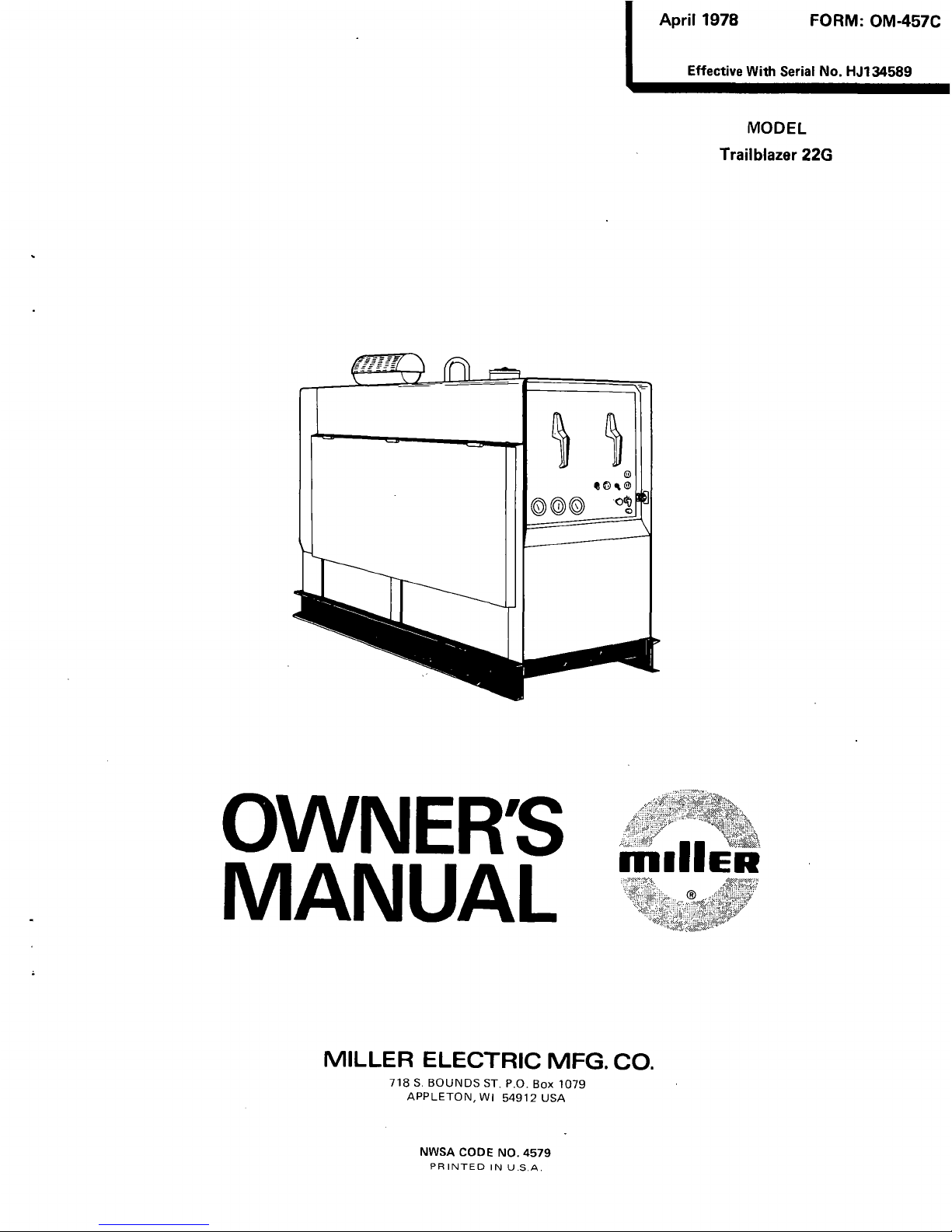
Miller HJ134589, Trailblazer 22G Owner's Manual
April
1978
FORM:
OM-457C
MODEL
Trailblazer
22G
OWN
ERS
MANUAL
ITIIIIER
MILLER
ELECTRIC
MFG.
CO.
718S.BOUNDS
ST.
P.O.
Box
1079
APPLETON,
WI
54912
USA
Effective
With
Serial
No.
HJ134589
NWSA
CODE
NO.
4579
PRINTED
IN
U.S.A.
LIMITED
WARRANTY
EFFECTIVE:
FEBRUARY
20,
1978
a
This
warranty
supersedes
all
previous
MILLER
warranties
and
is
ex
clusive
with
no
other
guarantees
or
warranties
expressed
or
implied.
LIMITED
WARRANTYMiller
Electric
Mfg.
Co..
Apple-
1.
Arc
welders,
power
sources,
and
components.
.
1
year
ton,
Wisconsin
warrants
to
Customer
that
all
new
and
unused
2.
Original
main
power
rectifiers
3
years
Equipment
furnished
by
Miller
is
free
from
defect
in
(Labor
1
year
only)
workmanship
and
material
as
of
the
time
and
place
of
delivery
by
Miller.
No
warranty
is
made
by
Miller
with
3.
All
welding
guns
and
feeder/guns
90
days
respect
to
engines,
trade
accessories
or
other
items
manu-
4.
All
other
Millermatic
Feeders
1
year
factured
by
others.
Such
engines,
trade
accessories
and
other
provided
that
the
user
so
notifies
Miller
in
writing
within
thirty
items
are
sold
subject
to
the
warranties
of
their
respective
(30)
days
of
the
date
of
such
failure.
manufacturers,
if
any.
The
manufacturers
warranty
on
5.
Replacement
or
repair
parts
exclusive
of
labor
60
days
engines
is
for
a
period
of
one
year.
MILLER
warranty
does
not
apply
to
components
having
ANY
EXPRESS
WARRANTY
NOT
PROVIDED
normal
useful
life
of
less
than
one
(1)
year,
such
as
spot
HEREIN
AND ANY
IMPLIED
WARRANTY,
GUARANTY
welder
tips,
relay
and
contactor
points,
MILLERMATIC
OR
REPRESENTATION
AS
TO
PERFORMANCE,
AND
parts
that
come
in
contact
with
the
welding
wire
including
ANY
REMEDY
FOR
BREACH
OF
CONTRACT
WHICH,
nozzles
and
nozzle
insulators
where
failure
does
not
result
BUT
FOR
THIS
PROVISION,
MIGHT
ARISE
BY
from
defect
in
workmanship
or
materiat.
IMPLICATION,
OPERATION
OF
LAW,
CUSTOM
OF
TRADE
OR
COURSE
OF
DEALING,
INCLUDING
ANY
In
the
case
of
Millers
breach
of
warranty
or
any
other
IMPLIED
WARRANTY
OF
MERCHANTABILITY
OR
OF
duty
with
respect
to
the
quality
of
any
goods,
the
exclusive
remedies
therefor
shall
be,
at
Millers
option,
(1)
repair
or
(2)
FITNESS
FOR
PARTICULAR
PURPOSE,
WITH
RESPECT
replacement
or,
where
authorized
in
writing
by
Miller
in
TO
ANY
AND
ALL
EQUIPMENT
FURNISHED
BY
appropriate
cases,
(3)
the
reasonable
cost
of
repair
or
MILLER
IS
EXCLUDED
AND
DISCLAIMED
BY
MILLER.
replacement
at
an
authorized
Miller
service
station
or
(4)
payment
of
or
credit
for
the
purchase
price
(less
reasoi~able
EXCEPT
AS
EXPRESSLY
PROVIDED
BY
MILLER
IN
depreciation
based
upon
actual
use)
upon
return
of
the
goods
WRITING,
MILLER
PRODUCTS
ARE
INTENDED
FOR
at
Customers
risk
and
expense.
All
transactions
are
FOB.
ULTIMATE
PURCHASE
BY
COMMERCIAL/INDUSTRIAL
$
Appleton.
Wisconsin.
Upon
receipt
of
notice
of
apparent
USERS
AND
FOR
OPERATION
BY
PERSONS
TRAINED
defect
or
failure,
Miller
shall
instruct
the
claimant
on
the
AND
EXPERIENCED
IN
THE
USE
AND
MAINTENANCE
warranty
claim
procedures
to
be
followed.
OF
WELDING
EQUIPMENT
AND
NOT,
FOR
CONSUMERS
As
a
matter
of
general
policy
only,
Miller
may
honor
an
OR
CONSUMER
USE.
MILLER
WARRANTIES
DO
NOT
original
users
warranty
claims
on
warranted
Equipment
in
EXTEND
TO,
AND
NO
RESELLER
IS
AUTHORIZED
TO
the
event
of
failure
resulting
from
a
defect within
the
following
periods
from
the
date
of
delivery
of
Equipment
to
EXTEND
MILLERS
WARRANTIES
TO,
ANY
the
original
user:
CONSUMER.
ERRATA
SHEET
After
this
manual
was
printed,
refinements
in
equipment
design
occurred.
This
sheet
lists
ex.cenXioi~s.tadata
aooearina
later
in
this
manual.
AMENDMENT
TO
SECTION
3
INSTALLATION
Amend
Section
3-3.
EQUIPMENT
GROUNDING
TERMINAL
Normally
engine-driven
welding
generators
do
not
require
grounding.
However,
this
machine
has
auxiliary
power
plant
capability;
therefore,
grounding
of
the
frame
and
case
is
recommended.
Also,
unusual
circumstances
may
re
quire
machine
grounding.
For
these
reasons
a
convenient
grounding
terminal
is
provided
on
all
weld/power
units.
For
detailed
grounding
instructions
consult
your,
local
or
state
codes
and
the
latest
issueofthe
National
Electrical
Code.
If
additional
information
regarding
your
particular
operating
circumstances
and/or
grounding
requirements
is
needed,
consult
a
qualified
electrician
or
your
dealer.
After
determining
the
extent
to
which
any
grounding
re
quirements
apply
to
your
particular
situation,
follow
them
explicitly.
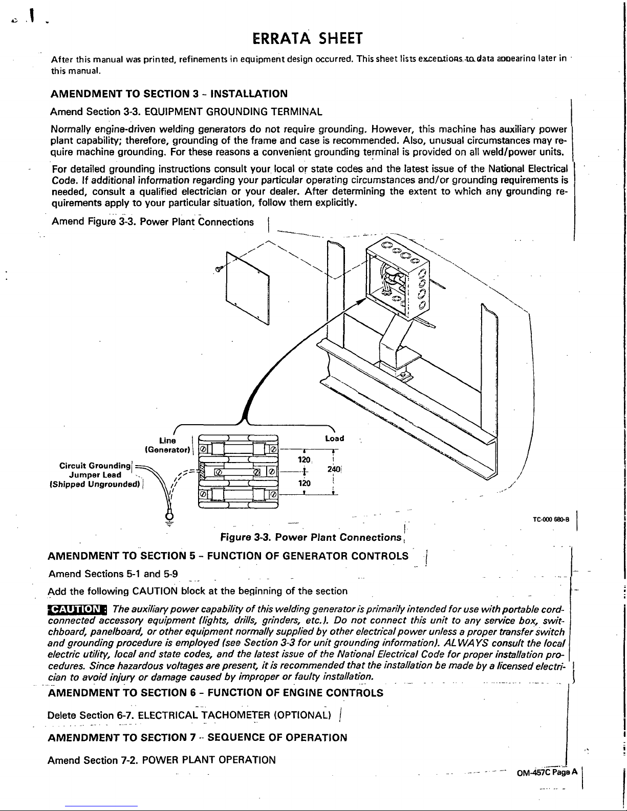
Circuit
Groundingl
Jumper
Lead
IShipped
Ungrounded)
AMENDMENT
TO
SECTION
5-
FUNCTION
OF
GENERATOR
CONTROLS
Amend
Sections
5-1
and
5-9
Add
the
following
CAUTION
blockatthe
beginning
of
the
section
TC-000
680-B
Amend
Figure
3-3.
Power
Plant
Connections
Figure
3-3.
Power
Plant
Connections
CAUTION:
_______
The
auxiliary
power
capability
of
this
welding
generator
is
primarily
intended
for
use
with
portable
cord-
connected
accessory
equipment
(lights,
drills,
grinders,
etc.).
Do
not
connect
this
unit
to
any
service
box,
swit
chboard,
panelboard,
or
other
equipment
normally
supplied
by
other
electrical
power
unless
a
proper
transfer
switch
and
grounding
procedure
is
employed
(see
Section
3-3
for
unit
grounding
information).
ALWAYS
consult
the
local
electric
utility,
local
and
state
codes,
and
the
latest
issueofthe
National
Electrical
Code
for
proper
installation
pro
cedures.
Since
hazardous
voltages
are
present,
it
is
recommended
that the
installation
be
made
by
a
licensed
electri
-
clantoavoid
injury
or
damage
caused
by
improper
or
faulty
installation.
AMENDMENT
TO
SECTION
6-
FUNCTION
OF
ENGINE
CONTROLS
Delete
Section
6-7.
ELECTRICAL
TACHOMETER
(OPTIONAL)
/
AMENDMENT
TO
SECTION
7-
SEQUENCE
OF
OPERATION
Amend
Section
7-2.
POWER
PLANT
OPERATION
OM-457C
Page
A
CAUTION.:
-
Add
CAUTION
block
at
beginning
of
Section
/
The
weld
output
terminals
are
electrically
energized
when
the
engine
is
running.
Disconnect
the~
we/ding
cables
when
not
we/ding
and
do
not
touch
the
output
terminals
when
the
engineisrunning.
AMENDMENT
TO
SECTION
9-
ENGINE
MAINTENANCE
Amend
Section
9-3.
GOVERNOR
SERVICE
Weld
speed
of
this
engine
is
1850
rpm.
Amend
Section
9-4.
CARBURETOR
FLOAT
SETTING
Carburetor
Change
Effective
With
Serial
No.
HJ185451
I~1t~
Do
not
bend,
twist,
or
apply
pressure
on
the
float
body.
The
float
body,
when
viewed
from
the
free
end,
must
be
centered
between
and
at
right
angles
to
the
machined
surface,
and
must
move
freely
on
the
float
axle.
This
engine
is
equipped
with
a
Teledyne
Walbro
carburetor.
To
ensure
correct
fuel
level
in
the
float
chamber,
check
distance
(dimension
A,
Figure
9-1)
from
top
of
float
to
machined
surface
of
throttle
body
(no
gasket)
with
throttle
body
inverted.
This
dimension
should
be
1-1/16
inches
plus
or
minus
.020
inch.
To
increaseordecrease
distance
from
the
top
of
the
float
body
to
the
machined
surface,
use
a
long
nose
pliers
and
bend
the
float
lever
at
a
point
closetothe
float
body.
Delete
Figure
9-2.
Carburetor
Float
Setting
Amend
Section
9-9.
IDLE
CONTROL/GOVERNOR
LINKAGE
ADJUSTMENT
(Figure
9-7)
Amend
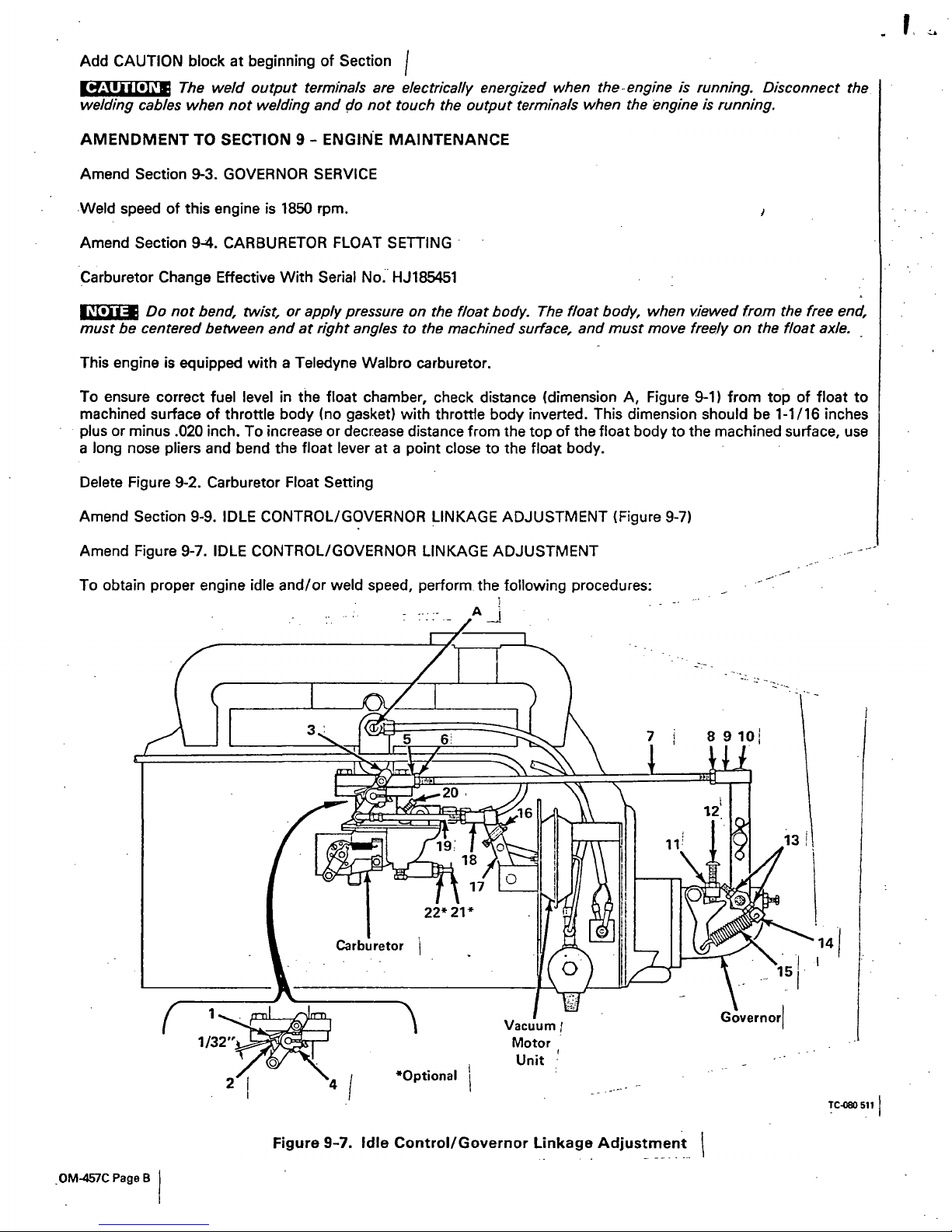
Figure
9-7.
IDLE
CONTROL/GOVERNOR
LINKAGE
ADJUSTMENT
To
obtain
proper
engine
idle
and/or
weld
speed,
perform~
the
following
procedures:
0M-457C
Page
B
Figure
9-7.
Idle
Control/Governor
Linkage
Adjustment
TCO8O
511
IMPORTANT
CAUTION
IMPORTANT
IMPORTANT
1.
Loosen
the
linkage
nuts
(6
&
8)
and
remove
the
hardware
(10)
securing
the
linkage
socket
(9)
to
the
governor.
Rotate
thelinkage
socket
(9)
until
the
throttle
stop
plate
(2)
is
about
1/32
inch
from
the
stop
(1).
A
clockwise
rotation
of
the
linkage
socket
(9)
will
shorten
the
governor
linkage
(7)
and
reduce
the
gap;
a
counterclockwise
rotationofthe
linkage
socket
(9)
will
lengthen
the
governor
linkage
(7)
and
widen
the
gap.
(In
some
cases
it
may
be
necessary
to
adjust
the
linkage
itself
to
obtain
the
1/32
inch
gap
required.)
Tighten
the
linkage
socket
nuts
(6
&
8)
to
lock
the
position
of
the
linkage
sockets
(5&9).
______________
Check
the
linkage
(7J
for
freedom
of
movement
throughout
its
entire
travel.Ifthe
linkage
is
binding
due
to
the
linkage
socket
nuts
(5
&
9)
being
out
of
proper
alignment,
loosen
the
linkage
socket
nuts
(6
&
8)
and
rotate
the
sockets
(5
&
9)
slightly
until
unrestricted
movement
of
the
linkage
(7)
is
restored.
Tighten
the
linkage
socket
nuts
(6&8).
Ensure
that
body
limbs
are
clear
of
the
fan
and
the
vacuum
motor
unit
before
starting
or
working
on
the
~.
engine.
-------
--------~
----
-
-
-:~-~
-
2.
Recheck
all
adjustments
made
thus
far.
Place
the
IDLE
CONTROL
switch
in
the
LOCK
OUT
position.
Start
the
engine
and
allow
it
to
reach
normal
operating
temperature
(about
five
minutes).
Ensure
that
the
CHOKE
control
is
pushed
fully
in
at
this
time.
-
3.
Pull
the
arm
(3)
toward
the
front
of
the
welding
generator
to
the
idle
position.
Maintain
pressure
on
the
arm
(3)
to
butt
against
the
idle
screw
(4)
throughout
the
following
adjustments:
A.
Rotate
the
idle
screw
(4)
to
obtain
550
rpm.
Clockwise
rotation
of
the
screw
(4)
will
increase
engine
rpm,
whereas
counterclockwise
rotationofthe
screw
(4)
will
decrease
engine
rpm.
B.
Rotate
the
idle
mixture
adjustment
screw
(20)
counterclockwise
until
the
engine
begins
to
falter
or
roll;
then
rotate
the
screw
(20)
clockwise
until
the
engine
operates
smoothly.
Rotating
the
screw
(20)
clockwise
restricts
the
fuel
flow,
making
the
air-fuel
mixture
leaner.
Rotating
the
screw
(20)
counterclockwise
admits
more
fuel,
making
the
air-fuel
mixture
richer.
Ensure
that
the
vacuum
motor
idle
screw
(16)
butts
against
the
vacuum
motor
unit
mounting
plate
BEFORE
the
throttle
stop
plate
(2)
butts
against
the
idle
screw
(4)
priortop/acing
the
IDLE
CONTROL
switch
in
the
AUTOMA
TIC
IDLE
position.
To
obtain
this
condition
it
may
be
necessary
to
adjust
screw
(16).
Check
by
manually
pivoting
the
vacuum
motor
arm
(17)
until
screw
(16)
butts
against
the
mounting
plate.
4.
Place
the
IDLE
CONTROL
switchinthe
AUTOMATIC
IDLE
position.
Operation
of
the
idling
deviceisautomatic
when
the
IDLE
CONTROL
switch
isinthe
AUTOMATIC
IDLE
position.
When
the
engine
is
running,
engine
rpm
will
remain
at
idle
until
an
arc
is
established,
at
which
time
the
engine
immediately
comes
up
to
weld
rpm.
When
the
arc
is
broken,
a
time
delay
will
exist
before
the
engine
begins
to
return
to
idle
rpm.
The
length
of
this
time
delay
is
controlledbythe
setting
of
the
time-delay
screw
A
in
Figure
9-7.
If
the
engine
does
not
go
to
idle
rpm
after
about
ten
seconds,
adjust
the
time-delay
screw
(A)
for
the
desired
time
delay.
This
screw
is
located
on
the
vacuum
line
fitting
going
into
the
intake
manifold
of
the
engine.~
5.
When
the
engine
has
gone
to
idle
rpm,
adjust
screw
(16)
until
1200
rpm
is
obtained.
I~EIi11~
Do
not
readjust
the
idle
rpm
screw
(4)
when
adjusting
the
vacuum
motor
idle
rpm.
-
______________
Check
the
linkage
(19)
for
freedom
of
movement
throughout
its
entire
travel.
If
the
linkageisbinding
due
to
the
linkage
socket
(18)
being
outof
proper
alignment
with
the
fixed
end,
adjust
the
tength
of
the
linkage.
It
will-
then
be
necessary
to
readjust
the
vacuum
motor
idle
screw
(16)
and
repeat
Steps
4
and
5.
Is~..tU.I
I
~
~
Ensure
that
body
limbs
are
clear
of
the
fan
and
the
vacuum
motor
unit
before
working
on
the
engine.
6.
Place
the
IDLE
CONTROL
switch
in
the
LOCK
OUT
position.
Loosen
the
governor
speed
adjusting
screw
secur
ing
nut
(11).
Adjust
the.governor
speed
adjustment
screw
(12)
until
a
high
idle
rpm
of
1850
is
obtained.
Tighten
the
securing
nut
(11)
to
maintain
the
governor
speed
setting.
7.
Check
the
governor
engine
regulation
by
applying
and
removing
the
engine
load.
If
a
governor
sensitivity
adjust
ment
is
deemed
necessary,
loosen
one
of
the
two
locking
nuts
(13)
and
proceed
with
the
following
instructions:
A.
IF
REGULATION
RANGE
IS
TOO
BROAD
-
Decrease
the
governor
spring
(15)
tension
by
sliding
the
sen
sitivity
adjustment
screw
(14)
inward.
B.
IF
REGULATION
RANGE
IS
TOO
NARROW
-
Increase
the
governor
spring
(15)
tension
by
sliding
the
sen
sitivity
adjustment
screw
(14)
outward.
C.
IF
ENGINE
SURGES
(HUNTS)
UNDER
LOAD
Increase
the
governor
spring
(15)
tension
by
sliding
the
sen
sitivity
adjustment
screw
(14)
outward.
-~
-
8.
Tighten
the
two
locking
nuts
(13)
to
maintain
the
desired
governor
sensitivity.
Readjust
the
governor
sensitivity
by
repeating
Step
7.
)
1~
Whenever
the
governor
sensitivity
(Step
7)
is
adjusted,
the
governor
speed
(Step
6)
MUST
be
readjusted.
Whenever
the
governor
speed
(Step
61
is
adjusted,
the
governor
sensitivfty
(Step
71
MAY
need
readjustment.
Amend
Section
9-10.
HIGH
ALTITUDE
CARBURETOR
MODIFICATION
(Optional)
(Figure
9-7)
The
Teledyne
Walbro
carburetor
can
be
equipped
with
an
adjustable
main
jet
for
high-altitude
operation
(above
4000
ft.).
Minor
adjustment
will
be
necessary
for
proper
operation
at
a
particular
altitude.
Whenever
a
carburetor
adjust
ment
is
deemed
necessary,
see
Figure
9-7
and
proceed
as
follows:
Loosen
the
main
adjustment
screw
locking
nut
(22).
Apply
a
near-full
engine
loadtothe
welding
generator.
Rotate
the
main
adjustment
screw
(21)
clockwise
until
the
engine
begins
to
falter
and
lose
RPM.
Rotate
the
main
adjustment
screw
(21)
counterclockwise
until
the
engine
operates
smoothly;
then
continue
counterclockwise
rotation
of
1/4
turn.
Rotating
the
screw
(21)
clockwise
restricts
the
fuel
flow,
making
the
air-fuel
mixture
leaner.
Rotating
the
screw
(21)
counterclockwise
admits
more
fuel,
making
the
air-fuel
mixture
richer.
Remove
the
engine
load.
Tighten
the
locking
nut
(22).
IMPORTANT
Restricting
the
fuel
flowtothe
point
where
the
mixture
is
too
lean
will-cause
valve
burning.
Delete
Figure
9-8.
High-Altitude
Carburetor
Adjustment
AMENDMENT
TO
SECTION
10
-
TROUBLESHOOTING
C
o~a
UETEA
(Q~T
C%AL)
OM-457C
PageD
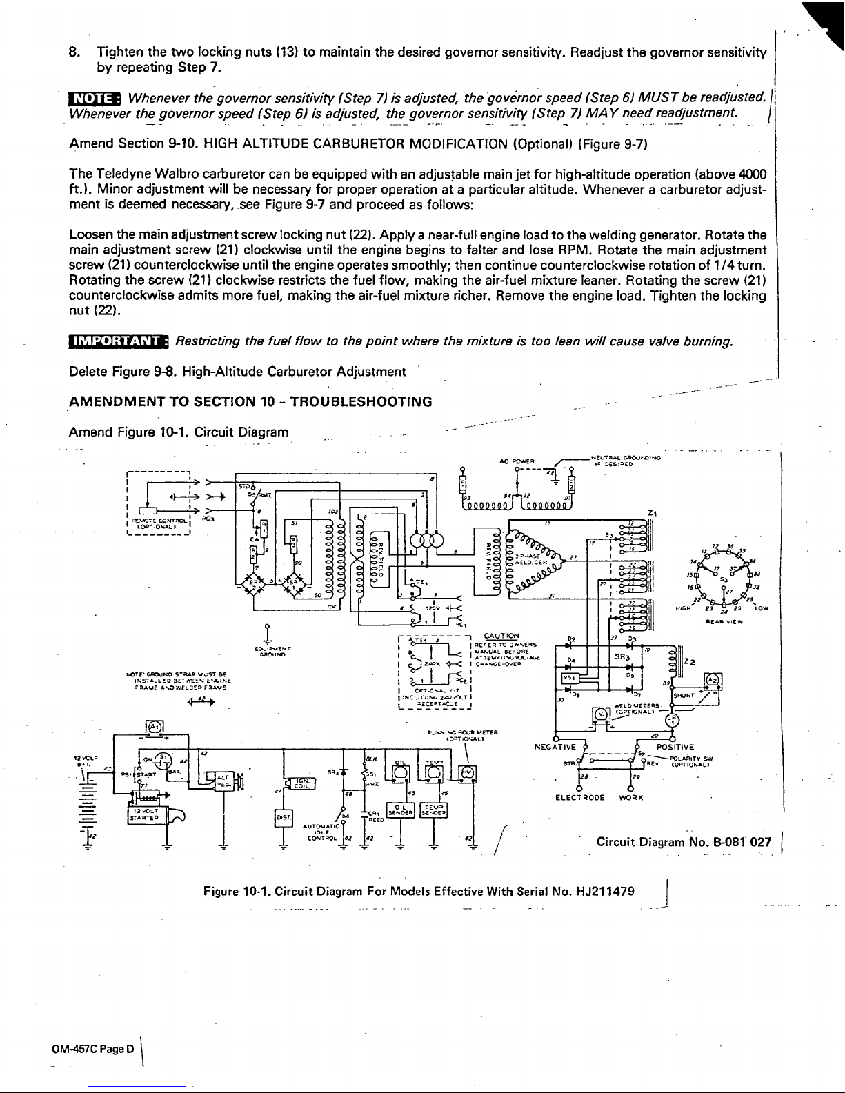
Figure
10-1.
Circuit
Diagram
For
Models
Effective
With
Serial
No.
HJ211479
Amend
Figure
10-1.
Circuit
Diagram
AC
EOWE3
,,_-_~___
5EU~A4~.
GRCcu~UIC
~
S~3ED
E~E1r
*.OTE
~
SIAAA
~
AE
AWE
A1.DWELE!R
jESUS
72
33
r.._77
~
;scfi
-~
~
127
J,~2
24
23
EOW
REAR
VIEW
CAUTION
I
I
I
c0)
~
-~<
CA~.GE-3VER
I
~
~7
I
I
NCI.~C:p~V
acE
~OLr
I
If
-
/
Circuit
Diagram
No.
B-081
027
)tem
Dia.
Part
No.
Listed
-
No.
Mkgs.
In
Parts
List
6
010318
33
053724
53
017421
77
Zi
036259
80
VS1
025932
OlO
493
053
359
Replaced
With
Part
No.
015
602
053
966
049685
036
377
024
017
Deleted
032
936
080
487
601158
079
486
010 014
010
891
030
170
011
609
Quantity
1
2
2
1
1
1
1
2
1
1
1
1
2
BE
SURE
TO
PROVIDE
MODEL
AND
SERIAL
NUMBERS
WHEN
ORDERING
REPLACEMENT
PARTS.
OM-457C
Page
E
Description
Page
4
Page
5
97
TAC
HM
032
936
032
936
039
269
100
146
S2,5
VALVE,
shut-off
w/strainer
-
fuel
GUARD,
fan
CATCH,
door
REACTOR
SUPPRESSOR,
0.75
uf
65
volts
ac
(Eff
with
S/N
HK311202)
METER
(dia.
mkg.
changed)
FUSE
BOX
(Eff
with
S/N
HJ211479)
BLANK,
snap
-
in
7/8
(Eff
with
S/N
HJ21
1479)
COVER,
junction
box
(Eff
with
S/N
HJ21
1479)
CLAMP,
steel
-
cushion
3/4
dia
x
13/64
hole
(Eff
with
S/N
HJ21
1479)
BLANK,
snap
-
in1inch
dia
(Eff
with
S/N
HJ211479)
BUSHING,snapin3/4IDx1
SWITCH,
toggle
SPDT
15
amp
125
volts

p.
Section
No.
TABLE
OF
CONTENTS
Page
No.
SECTION
1
SAFETY
RULES
FOR
OPERATION
OF
ARC
WELDING
POWER
SOURCE
SECTION
2
INTRODUCTION
2-1.
2-2.
2-3.
2-4.
General
Receiving-Handling
Description
Safety
SECTION
3
INSTALLATION
3-1.
3-2.
3
-
3.
3-4.
4-1.
4
-
2.
4
-
3.
4
-
4.
4-5.
5-1.
5
-
2.
5-3.
5-4.
5-5.
5
-
6.
5-7.
5-8.
5-9.
6-1.
6-2.
6-3.
6-4.
6-5.
6-6.
6-7.
6
-
8.
7-
1.
7
-
2.
7
-
3.
7
-
4.
Location
Weld
Output
Connections
Equipment
Grounding
Terminal
Remote
Amperage
Control
Connections
6677
7
8
8
8
9
9
10
10
10
10
10
11
11
11
11
12
12
12
12
12
12
12
12
13
13
13
13
1
-1.
1
-
2.
1
-
3.
1-4.
Introduction
General
Precautions
Arc
Welding
Standards
Booklet
Index
1
3
4
5
5
5
5
3-
5.
120/240
Volts
AC
Terminals..
SECTION
4
ENGINE
PREPARATION
Lubrication
Coolant
System
Preparing
New
Battery
For
Service
Air
Cleaner
Fuel
SECTION
5
FUNCTION
OF
GENERATOR
CONTROLS
120
Volts
AC
Receptacle
Range
Switch
Fine
Amperage
Control
Remote
Amperage
Control
Volt-Ampere
Curves
Duty
Cycle
Polarity
Switch
Meters
240
Volts
AC
Duplex
Receptacle
SECTION
6
FUNCTION
OF
ENGINE
CONTROLS
Choke
Control
Start
Push
Button
And
Switch
Idle
Control
Switch
Engine
Ammeter
Temperature
Gauge
Oil
Pressure
Gauge
Electrical
Tachometer
Total
Hour
Meter
SECTION
7
SEQUENCE
OF
OPERATION
Sheilded
Metal-Arc
(SMAW)
Welding
Power
Plant
Operation
Starting
The
Engine
Engine
Shut
Down
Section
No.
Page
No.
SECTION
8
GENERATOR
MAINTENANCE
8-1.
General
14
8
-
2.
Collector
Ring
Brushes
14
8-
3.
Welding
Cables
14
SECTION
9
ENGINE
MAINTENANCE
9-1.
Lubrication
14
9~
2.
Coolant
System
14
9-3.
Governor
Service
15
9.
4.
Carburetor
Float
Setting
15
9-
5.
Vacuum
Circuit
Air
Filter
15
9.6.Idle
Control
Time
Delay
Adjustment
15
9-
7.
Carburetor
Air
Temperature
Selector
15
9-8.Air
Cleaner
Service
16
9-
9.
Idle
Control/Governor
Linkage
Adjustment
17
9.10.
High
Altitude
Carburetor
Modification
18
9.11.
Key
Type
Ignition
Switch
Lubrication
18
9-12.
Spark
Arrestor
18
SECTION
10
TROUBLESHOOTING
PARTS
LIST
SECTION
1-SAFETY
RULES
FOR
OPERATION
OF
ARC
WELDING
POWER
SOURCE
1-1.
INTRODUCTION
1-2.
A.
We
learn
by
experience.
Learning
safety
through
personal
experience,
like
a
child
touching
a
hot
stove
is
harmful,
wasteful,
and
unwise.
Let
the
experience
of
others
teach
you.
Safe
practices
developed
from
experience
in
the
use
of
weld
ing
and
cutting
are
described
in
this
manual.
Research,
devel
opment,
and
field
experience
have
evolved
reliable
equipment
and
safe
installation,
operation,
and
servicing
practices.
Acci
dents
occur
when
equipmentisimproperly
used
or
main
tained.
The
reason
for
the
safe
practices
may
not
always
be
given.
Some
are
based
on
common
sense,
others
may
require
technical
volumes
to
explain.
It
is
wiser
to
follow
the
rules.
Read
and
understand
these
safe
practices
before
attempting
to
install,
operate,
or
service
the
equipment.
Comply
with
these
procedures
as
applicable
to
the
particular
equipment
used
and
their
instruction
manuals,
for
personal
safety
and
for
the
safety
of
others.
Failure
to
observe
these
safe
practices
may
cause
serious
in
jury
or
death.
When
safety
becomes
a
habit,
the
equipment
can
be
used
with
confidence.
These
safe
practices
are
divided
into
two
Sections:
1
-
General
Precautions,
common
to
arc
welding
and
cutting;
and
2
-
Arc
Welding
(and
Cutting)
(only).
Reference
standards:
Published
Standards
on
safety
are
also
available
for
additional
and
more
complete
procedures
than
those
given
in
this
manual.
They
are
listedinthe
Standards
Index
in
this
manual.
ANSI
Z49.1
is
the
most
complete.
The
National
Electrical
Code,
Occupational
Safety
and
Health
Administration,
local
industrial
codes,
and
local
in
spection
requirements
also
provide
a
basis
for
equipment
in
stallation,
use,
and
service.
GENERAL
PRECAUTIONS
Burn
Prevention
Wear
protective
clothing
-
leather
(or
asbestos)
gauntlet
gloves,
hat,
and
high
safety-toe
shoes.
Button
shirt
collar
and
pocket
flaps,
and
wear
cuffless
trousers
to
avoid
entry
of
sparks
and
slag.
Wear
helmet
with
safety
gogglesorglasses
with
side
shields
underneath,
appropriate
filter
lenses
or
plates
(protected
by
clear
cover
glass).
This
is
a
MUST
for
weldingorcutting,
(and
chipping)
to
protect
the
eyes
from
radiant
energy
and
flying
metal.
Replace
cover
glass
when
broken,
pitted,
or
spattered.
See
1-3A.2.
Avoid
Oily
or
greasy
clothing.
A
spark
may
ignite
them.
Hot
metal
such
as
electrode
stubs
and
workpieces
should
never
be
ha,dled
without
gloves.
Medical
first
aid
and
eye
treatment.
First
aid
facilities
and
a
qualified
first
aid
person
should
be
available
for
each
shift
unless
medical
facilities
are
close
by
for
immediate
treatment
of
flash
burnsofthe
eves
and
skin
burns.
Ear
plugs
should
be
worn
when
working
on
overhead
or
in
a
confined
space.
A
hard
hat
should
be
worn
when
others
work
overhead.
Flammable
hair
preparations
should
not
be
used
by
persons
intending
to
weld
or
cut.
B.
Toxic
Fume
Prevention
Adequate
ventilation.
Severe
discomfort,
illness
or
death
can
result
from
fumes,
vapors,
heat,
or
oxygen
enrichment
or
depletion
that
welding
(or
cutting)
may
produce.
Prevent
them
with
adequate
ventilationasdescribed
in
ANSI Stan
dard
Z49.1
listed
1
in
Standards
index.
NEVER
ventilate
with
oxygen.
Lead
-,
cadmium
-.
zinc
-.
mercury
-,
and
beryllium
-
bearing
and
similar
materials,
when
welded
(Or
cut)
may
produce
harmful
concentrations
of
toxic
fumes.
Adequate
local
exhaust
ventilation
must
be
used,
or
each
person
in
the
area
as
well
as
the
operator
must
wear
an
air-supplied
respirator.
For
beryllium,
both
must
be
used.
Metals
coated
with
or
containing
materials
that
emit
toxic
fumes
should
not
be
heated
unless
coating
is
removed
from
the
work
surface,
the
area
is
well
ventilated,
or
the
operator
wears
an
air-suppied
respirator.
Work
in
a
confined
space
only
while
it
is
being
ventilated
and,
if
necessary,
while
wearing
an
air-supplied
respirator.
Gas
leaks
in
a
confined
space
should
be
avoided.
Leaked
gas
in
large
quantities
can
change
oxygen
concentration
danger
ously.
Do
not
bring
gas
cylinders
intoaconfined
space.
Leaving
confined
space,
shut
OFF
gas
supply
at
source
to
prevent
possible
accumulation
of
gases
in
the
space
if
down
stream
valves
have
been
accidently
opened
or
left
open.
Check
to
be
sure
that
the
space
is
safe
before
re-entering
it.
Vapors
from
chlorinated
solvents
can
be
decomposed
by
the
heat
of
the
arc
(or
flame)
to
form
PI-IOSGENE,
a
highly
toxic
gas,
and
other
lung
and
eye
irritating
products.
The
ultra
violet
(radiant)
energy
of
the
arc
can
also
decompose
tn
chloroethylene
and
perchloroethylene
vapors
to
form
phos
gene.
DO
NOT
WELD
or
cut
where
solvent
vapors
can
be
drawn
into
the
welding
or
cutting
atmosphere
or
where
the
radiant
energy
can
penetrate
to
atmospheres
containing
even
minute
amounts
of
trichloroethylene
or
perchloroethylene.
C.
Fire
and
Explosion
Prevention
Causesoffire
and
explosion
are:
combustibles
reached
by
the
arc,
flame,
flying
sparks,
hot
slag
or
heated
material;
misuse
of
compressed
gases
and
cylinders;
and
short
circuits.
BE
AWARE
THAT
flying
sparks
or
falling
slag
can
pass
through
cracks,
along
pipes,
through
windows
or
doors,
and
through
wall
or
floor
openings,
Out
of
sight
of
the
goggled
operator.
Sparks
and
slag
can
fly
35
feet.
To
prevent
fires
and
explosion:
Keep
equipment
clean
and
operable,
free
of
oil,
grease,
and
(in
electrical
parts)
of
metallic
particles
that
can
cause
short
circuits.
If
combustibles
are
in
area,
do
NOT
weld
or
cut.
Move
the
work
if
practicable,
to
an
area
free
of
combustibles.
Avoid
paint
spray
rooms,
dip
tanks,
storage
areas,
ventilators.
If
the
work
cannot
be
moved,
move
combustibles
at
least35feet
away
Out
of
reach
of
sparks
and
heat;
or
protect
against
ignition
with
suitable
and
snug-fitting,
fire-resistant
covers
or
shields.
Walls
touching
combustibles
on
opposite
sides
should
not
be
welded
on
(or
cut).
Walls,
ceilings,
and
floor
near
work
should
be
protected
by
heat-resistant
covers
or
shields.
Fire
watcher
must
be
standing
by
with
suitable
fire
ex
tinguishing
equipment
during
and
for
some
time
after
weld
ing
or
cutting
if:
a.
appreciable
combustibles
(including
building
construc
tion)
are
within35feet
b.
appreciable
combustibles
are
further
than
35
feet
but
can
be
ignited
by
sparks
c.
openings
(concealed
or
visible)
in
floors
or
walls
within
35
feet
may
expose
combustibles
to
sparks
d.
combustibles
adjacent
to
walls,
ceilings,
roofs,
or
metal
partitions
can
be
ignited
by
radiant
or
conducted
heat.
Hot
work
permit
should
be
obtained
before
operation
to
ensure
supervisors
approval
that
adequate
precautions
have
been
taken.
After
work
is
done,
check
that
area
is
free
of
sparks,
glowing
embers,
and
flames.
-
An
empty
container
that
held
combustibles,
or
that
can
pro
duce
flammable
or
toxic
vapors
when
heated,
must
never
be
welded
on
or
cut,
unless
container
has
first
been
cleaned
as
described
in
AWS
Standard
A6.O,
listed3in
Standards
index.
OM-457
Page
1
This
includes:
a
thorough
steam
or
caustic
cleaning
(or
a
solvent
or
water
washing,
depending
on
the
combustibles
solubility)
followed
by
purging
and
inerting
with
nitrogen
or
carbon
dioxide,
and
using
protective
equipment
as
recom
mended
in
A6.0.
Waterfilling
just
below
working
level
may
substitute
for
inerting.
A
container
with
unknown
contents
should
be
cleaned
(see
paragraph
above).
Do
NOT
depend
on
sense
of
smell
or
sight
to
determine
if
it
is
safe
to
weld
or
cut.
Hollow
castings
or
containers
must
be
vented
before
welding
or
cutting.
They
can
explode.
Explosive
atmospheres.
Never
weld
or
cut
where
the
air
may
contain
flammable
dust,
gas,
or
liquid
vapors
(such
as
gaso
line).
D.
Compressed
Gas
Equipment
Standard
precautions.
Comply
with
precautions
in
this
manual,
and
those
detailedinCGA
Standard
P-i,
PRECAU
TIONS
FOR
SAFE
HANDLING
OF
COMPRESSED
GASES
~N
CYLINDERS,
listed
6
in
Standards
index.
1.
Pressure
Regulators
Regulator
relief
valve
is
designed
to
protect
only
the
regula
tor
from
overpressure;
it
is
not
intended
to
protect
any
downstream
equipment.
Provide
such
protection
with
one
or
more
relief
devices.
Never
connect
a
regulator
to
a
cylinder
containing
gas
other
than
that
for
which
the
regulator
was
designed.
Remove
faulty
regulator
from
service
immediately
for
repair
(first
close
cylinder
valve).
The
following
symptoms
indicate
a
faulty
regulator:
Leaks
-
if
gas
leaks
externally,
Excessive
Creep
-
if
delivery
pressure
continues
to
rise
with
downstream
valve
closed.
Faulty
Gauge
-
if
gauge
pointer
does
not
move
off
stop
pin
when
pressurized,
nor
returns
to
stop
pin
after
pressure
release.
Repair.
Do
NOT
attempt
repair.
Send
faulty
regulators
for
repair
to
manufacturers
designated
repair
center,
where
special
techniques
and
tools
are
used
by
trained
personnel.
2.
Cylinders
Cylinders
must
be
handled
carefully
to
prevent
leaks
and
damage
to
their
walls,
valves,orsafety
devices:
Avoid
electrical
Circuit
contact
with
cylinders
including
third
rails,
electrical
wires,
or
welding
circuits.
They
can
produce
short
circuit
arcs
that
may
lead
to
a
serious
accident.
(See
1-3C,)
ICCorDOT
marking
must
be
on
each
cylinder.
It
is
an
assurance
of
safety
when
the
cylinder
is
properly
handled.
Identifying
gas
content.
Use
only
cylinders
with
name
of
gas
marked
on
them;
do
not
rely
on
color
to
identify
gas
con
tent.
Notify
supplier
if
unmarked.
NEVER
DEFACE
or
alter
name,
number,
or
other
markings
on
a
cylinder.
It
is
illegal
and
hazardous.
Empties:
Keep
valves
closed,
replace
caps
securely;
mark
MT;
keep
them
separate
from
FULLS
and
return
promptly.
Prohibited
use.
Never
use
a
cylinder
or
its
contents
for
other
than
its
intended
use,
NEVER
as
~a
support
or
roller.
Locate
or
secure
cylinderssothey
cannot
be
knocked
over.
Passageways
and
work
areas.
Keep
cylinders
clear
of
areas
where
they
may
be
struck.
Transporting
cylinders.
With
a
crane,
useasecure
support
such
as
a
platform
or
cradle.
Do
NOT
lift
cylinders
off
the
ground
by
their
valves
or
caps,
or
by
chains,
slings,
or
mag
no
ts.
Do
NOT
expose
cylinders
to
excessive
heat,
sparks,
slag,
and
flame,
etc.
that
may
cause
rupture.
Do
not
allow
contents
to
exceed
130F.
Cool
with
water
spray
where
such
exposure
exists.
Protect
cylinders
particularly
valves
from
bumps,
falls,
falling
objects,
and
weather.
Replace
caps
securely
when
moving
cylinders.
Stuck
valve.
Do
NOT
use
a
hammer
or
wrench
to
open
a
cylinder
valve
that
can
not
be
opened
by
hand.
Notify
your
Supplier.
Mixing
gases.
Never
try
to
mix
any
gases
in
a
cylinder.
Never
refill
any
cylinder.
Cylinder
fittings
should
never
be
modified
or
exchanged.
3.
Hose
Prohibited
use.
Never
use
hose
other
than
that
designed
for
the
specified
gas.
A
general
hose
identification
rule
is:
red
for
fuel
gas,
green
for
oxygen,
and
black
for
inert
gases.
Use
ferrules
or
clamps
designed
for
the
hose
(not
ordinary
wire
or
other
substitute)
as
a
binding
to
connect
hoses
to
fittings.
No
copper
tubing
splices.
Use
only
standard
brass
fittings
to
splice
hose.
Avoid
long
runs
to
prevent
kinks
and
abuse.
Suspend
hose
off
ground
to
keep
it
from
being
run
over,
stepped
on,
or
other
wise
damaged.
Coil
excess
hose
to
prevent
kinks
and
tangles.
Protect
hose
from
damage
by
sharp
edges,
and
by
sparks,
slag,
and
open
flame.
Examine
hose
regularly
for
leaks,
wear,
and
loose
connec
tions.
Immerse
pressured
hose
in
water;
bubbles
indicate
leaks.
Repair
leaky
or
worn
hose
by
cutting
area
Out
and
splicing
(1-2D3).
Do
NOT
use
tape.
4.
Proper
Connections
Clean
cylinder
valve
outlet
of
impurities
that
may
clog
orifices
and
damage
seals
before
connecting
regulator.
Except
for
hydrogen,
crack
valve
momentarily,
pointing
outlet
away
from
people
and
sources
of
ignition.
Wipe
with
a
clean
lint-
less
cl
0th.
Match
regulator
to
cylinder.
Before
connecting,
check
that
the
regulator
label
and
cylinder
marking
agree,
and
that
the
regulator
inlet
and
cylinder
outlet
match.
NEVER
CON
NECT
a
regulator
designed
for
a
particular
gasorgases
to
a
cylindercontaining
any
other
gas.
Tighten
connections.
When
assembling
threaded
connections,
clean
and
smooth
seats
where
necessary.
Tighten.
If
connec
tion
leaks,
disassemble,
clean,
and
retighten
using
properly
fitting
wrench.
-
Adapters.
Use
a
CGA
adapter
(available
from
your
supplier)
between
cylinder
and
regulator,
if
one
is
required.
Use
two
wrenches
to
tighten
adapter
marked
RIGHT
and
LEFT
HAND
threads.
Regulator
outlet
(Or
hose)
connections
may
be
identified
by
right
hand
threads
for
oxygen
and
left
hand
threads
(with
grooved
hex
on
nut
or
shank)
for
fuel
gas.
5.
Pressurizing
Steps:
Drain
regulator
of
residual
gas
through
suitable
vent
before
opening
cylinder
(or
manifold
valve)
by
turning
adjusting
screw
in
(clockwise).
Draining
prevents
excessive
compression
heat
at
high
pressure
seat
by
allowing
seat
to
open
on
pressur
ization.
Leave
adjusting
screw
engaged
slightly
on
single-stage
regulators.
Standtoside
of
regulator
while
opening
cylinder
valve.
Open
cylinder
valve
slowly
so
that
regulator
pressure
in
creases
slowly.
When
gauge
is
pressurized
(gauge
reaches
regu
lator
maximum)
leave
cylinder
valve
.in
following
position:
For
oxygen,
and
inert
gases,
open
fully
to
seal
stem
against
possible
leak.
For
fuel
gas,
open
to
less
than
one
turn
to
permit
quick
emergency
shutoff.
Page
2
Use
pressure
charts
(available
from
your
supplier)
for safe
and
efficient,
recommended
pressure
settings
on
regulators.
Check
for
leaks
on
first
pressurization
and
regularly
there
after.
Brush
with
soap
solution
(capful
of
Ivory
Liquid
or
equivalent
per
gallon
of
water).
Bubbles
indicate
leak.
Clean
off
soapy
water
after
test;
dried
soap
is
combustible.
E.
User
Responsibilities
Remove
leaky
or
defective
equipment
from
service
immed
iately
for
repair.
See
Use!
Responsibility
statement
in
equip
ment
manual.
F.
Leaving
Equipment
Unattended
Close
gas
supply
at
source
and
drain
gas.
G.
Rope
Staging-Support
Rope
staging-support
should
not
be
used
for
welding
or
cut
ting
operation;
rope
may
burn.
1~3.
ARC
WELDING
Comply
with
precautions
in
1-1,
1-2,
and
this
section.
Arc
Welding,
properly
done,
is
a
safe
process,
but
a
careless
opera
tor
invites
trouble.
The
equipment
carries
high
currents
at
significant
voltages.
The
arc
is
very
bright
and
hot.
Sparks
fly,
fumes
rise,
ultraviolet
and
infrared
energy
radiates,
weld
ments
are
hot,
and
compressed
gases
may
be
used.
The
wise
operator
avoids
unnecessary
risks
and
protects
himself
and
others
from
accidents.
Precautions
are
described
here
and
in
standards
referenced
in
index.
A.
Burn
Protection
Comply
with
precautions
in
1-2.
The
welding
arc
is
intense
and
visibly
bright
Its
radiation
can
damage
eyes,
penetrate
lightweight
clothing,
reflect
from
light-colored
surfaces,
and
burn
the
skin
and
eyes.
Skin
burns
resemble
acute
sunburn,
those
from
gas-shielded
arcs
are
more
severe
and
painful.
DONT
GET
BURNED;
COMPLY
WITH
PRECAUTIONS.
1.
Protective
Clothing
Wear
long-sleeve
clothing
(particularly
for
gas-shielded
arc)
in
addition
to
gloves,
hat,
and
shoes
(1-2A).
As
necessary,
use
additional
protective
clothing
such
as
leather
jacket
or
sleeves,
flame-proof
apron,
and
fire-resistant
leggings.
Avoid
outergarments
of
untreated
cotton.
Bare
skin
protection.
Wear
dark,
substantial
clothing.
Button
collar
to
protect
chest
and
neck
and
button
pockets
to
pre
vent
entry
of
sparks.
2.
Eye
and
Head
Protection
Protect
eyes
from
exposure
to
arc.
NEVER
look
at
an
elec
tric
arc
without
protection.
Welding
helmet
or
shield
containing
a
filter
plate
shade
no.
12
or
denser
must
be
used
when
welding.
Place
over
face
before
striking
arc.
Protect
filter
plate
withaclear
cover
plate.
Cracked
or
broken
helmetorshield
should
NOT
be
worn;
radiation
can
pass
through
to
cause
burns.
Cracked,
broken,
or
loose
filter
plates
must
be
replaced
IM
MEDIATELY.
Replace
clear
cover
plate
when
broken,
pitted,
or
spattered.
Flash
goggles
with
side
shields
MUST
be
worn
under
the
helmet
to
give
some
protection
to
the
eyes
should
the
helmet
not
be
lowered
over
the
face
before
an
arc
is
struck.
Looking
at
an
arc
momentarily
with
unprotected
eyes
(particularly
a
high
intensity
gas-shielded
arc)
can
cause
a
retinal
burn
that
may
leave
a
permanent
dark
area
in
the
fieldofvision.
3.
Protection
of
Nearby
Personnel
Enclosed
welding
area.
For
production
welding,
a
separate
room
or
enclosed
bay
is
best.
In
open
areas,
surround
the
operation
with
low-reflective,
non.cornbustible
screens
or
panels.
Allow
for
free
air
circulation,
particularly
as
floor
level.
Viewing
the
weld.
Provide
face
shields
for
all
persons
who
will
be
looking
directly
at
the
weld.
Others
working
in
area.
See
that
all
persons
are
wearing
flash
goggles.
Before
starting
to
weld;
make
sure
that
screen
flaps
or
bay
doors
are
closed.
B.
Toxic
Fume
Prevention
Comply
with
precautions
in
1-2B.
Generator
engine
exhaust
must
be
ventedtothe
outside
air.
Carbon
monoxide
can
kill.
C.
Fire
and
Explosion
Prevention
Comply
with
precautions
in
1-2C.
Equipments
rated
capacity.
Do
not
overload
arc
welding
equipment.
It
may
overheat
cables
and
cause
a
fire.
Loose
cable
connections
may
overheatorflash
and
cause
a
fire.
Never
strike
an
arc
on
a
cylinder
or
other
pressure
vessel.
It
creates
a
brittle
area
that
can
cause
a
violent
rupture
or
lead
to
such
a
rupture
later
under
rough
handling.
D.
Compressed
Gas
Equipment
Comply
with
precautions
in
1-2D.
E.
Shock
Prevention
Exposed
hot
conductors
or
other
bare
metalinthe
welding
circuit,
or
in
ungrounded,
electrically-HOT
equipment
can
fatally
shock
a
person
whose
body
becomes
a
conductor.
DO
NOT
STAND,
SIT,
LIE,
LEAN
ON,
OR
TOUCH
a
wet
sur
face
when
welding,
without
suitable
protection.
To
protect
against
shock:
Keep
body
and
clothing
dry.
Never
work
in
damp
area
with
out
adequate
insulation
against
electrical
shock.
Stay
on
a
dry
duckboard,
or
rubber
mat
when
dampness
or
sweat
can
not
be
avoided.
Sweat,
sea
water,
or
moisture
between
body
and
an
electrically
HOT
part
-
or
grounded
metal-reduces
the
body
surface
electrical
resistance,
enabling
dangerous
and
possibly
lethal
currents
to
flow
through
the
body.
1.
Grounding
the
Equipment
When
installing,
connect
the
frames
of
each
unit
such
as
welding
power
source,
control,
i&ork
table,
and
water
circula
tor
to
the
building
ground.
Conductors
must
be
adequate
to
carry
ground
currents
safely.
Equipment
made
electrically
HOT
by
stray
current
may
shock,
possibly
fatally.
Do
NOT
GROUND
so
electrical
conduit,
or
to
a
pipe
carrying
ANY
gas
or
a
flammable
liquid
such
as
oil
or
fuel.
Three-phase
connection.
Check
phase
requirement
of
equip
ment
before
installing.
If
only
3-phase
power
is
available,
connect
single-phase
equipment
to
only
two
wires
of
the
3-phase
line.
Do
NOT
connect
the
equipment
ground
lead
to
the
third
(live)
wire,
or
the
equipment
will
become
electri-.
cally
HOT
-
a
dangerous
condition
that
can
shock,
possibly
fatally.
Before
welding,
check
ground
for
continuity.
Be
sure
conduc
tors
are
touching
bare
metal
of
equipment
frames
at
connec
tions.
If
a
line
cord
with
a
ground
lead
is
provided
with
the
equip
ment
for
connection
to
a
switchbox,
connect
the
ground
lead
to
the
grounded
switchbox.
If
a
three-prong
plug
is
added
for
connection
to
a
grounded
mating
receptacle,
the
ground
lead
must
be
connected
to
the
ground
prong
only.
If
the
line
cord
comes
with
a
three-prong
plug,
connect
to
a
grounded
mating
receptacle.
Never
remove
the
ground
prong
from
a
plug,
or
use
a
plug
with
a
broken
off
ground
prong.
Trademark
of
Proctor
&
Gamble.
OM-457
Page
3
2.
Electrode
Holders
Fully
insulated
electrode
holders
should
be
used.
Do
NOT
use
holders
with
protruding
screws.
3.
Connectors
Fully
insulated
lock-type
connectors
should
be
used
to
join
welding
cable
lengths.
4.
Cables
Frequently
inspect
cables
for
wear,
cracks
and
damage.
IMMEDIATELY
REPLACE
those
with
excessively
worn
or
damaged
insulation
to
avoid
possibly
-
lethal
shock
from
bared
cable.
Cables
with
damaged
areas
may
be
taped
to
give
resistance
equivalent
to
original
cable.
Keep
cable
dry,
free
of
oil
and
grease,
and
protected
from
hot
metal
and
sparks.
5.
Terminals
And
Other
Exposed
Parts
Terminals
and
other
exposed
parts
of
electrical
units
should
have
insulating
covers
secured
before
operation.
6.
Electrode
Wire
Electrode
wire
becomes
electrically
HOT
when
the
power
switch
of
gas
metal-arc
welding
equipment
is
ON
and
welding
gun
trigger
is
pressed.
Keep
hands
and
body
clear
of
wire
and
other
HOT
parts.
7.
Safety
Devices
Safety
devices
such
es
interlocks
and
circuit
breakers
should
not
be
disconnected
or
shunted
out.
Before
installation,
inspection,
or
service,
of
equipment,
shut
OFF
all
power
and
remove
line
fuses
(or
lock
or
red-t~
switches)
to
prevent
accidental
turning
ON
of
power.
Discon.
nect
all
cables
from
welding
power
source,
and
pull
all
115
volts
line-cord
plu~.
Do
not
open
power
circuit
or
change
polarity
while
welding.
If,
in
an
emergency,
it
must
be
disconnected,
guard
against
shock
burns,
or
flash
from
switch
arcing.
Leaving
equipment
unattended.
Always
shut
OFF
and
dis
connect
all
power
to
equipment.
Power
disconnect
switch
must
be
available
near
the
welding
power
source.
1-4.
STANDARDS
BOOKLET
INDEX
For
more
information,
refer
to
the
following
standards
or
their
latest
revisions
and
comply
es
applicable:
1.
ANSI
Standard
Z49.1,
SAFETY
IN
WELDING
AND
CUTTING
obtainable
from
the
American
Welding
Society,
2501
NW
7th
St.
Miami;
Fla.
33125.
2.
ANSI
Standard
Z87.i,
SAFE
PRACTICE
FOR
OCCUPA
TION
AND
EDUCATIONAL
EYE
AND
FACE
PROTEC
TION,
obtainable
from
American
National
Standards
Institute,
1430
Broadway.
New
York,
N.Y.
10018.
3.
American
Welding
Society
Standard
A6.0.
WELDING
AND
CUTTING
CONTAINERS
WHICH
HAVE
HELD
COMBUSTIBLES,
obtainable
same
as
item
1.
4.
NFPA
Standard
51,
OXYGEN-FUEL
GAS
SYSTEMS
FOR
WELDING
AND
CUTTING,
obtainable
from
the
National
Fire
Protection
Association,
470
AtlantIc
Avenue,
Boston,
Mass.
02210.
5.
NFPA
Standard
51B,
CUTTING
AND
WELDING
PRO.
CESSES,
obtainable
same
as
item
4.
6.
CGA
Pamphlet
P-i.
SAFE
HANDLING
OF
COM
PRESSED
GASES
IN
CYLINDERS,
obtainablefrom
the
Compressed
Gas
Association,
500
Fifth
Avenue,
New
York,
N.
Y.
10036.
7.
OSHA
Standard
29
CFR,
Part
1910,
Subpart
Q,
WELD.
ING,
CUTTING
AND
BRAZING.
Page
4
 Loading...