

Miller GPS-1000, GPS-1500V, GPS-1500 Owner's Manual
September
1980
FORM:
OM-267B
Effective
With
Serial
No.
JA372254
MODEL
GPS-1000
GPS-1
500
GPS-1500V
hullER
~
fi$IT
MILLER
ELECTRIC
MFG.
CO.
718
S.
BOUNDS
ST.
P.O.
Box
1079
APPLETONWI54912
USA
ADDITIONAL
COPY
PRICE
55
CENTS
NWSA
CODE
NO.
4579
PRINTED
IN
U.S.A.
OWNERS
MANUAL

~
~
i-
~
~-~
~~
LIMITED
WARRANTY
EFFECTIVE:
JUNE
1,
1979
This
warranty
supersedes
all
previous
MILLER
warranties
and
is
ex
clusive
with
no
other
guarantees
or
warranties
expressed
or
implied.
LIMITED
WARRANTY-Subject
to
the
terms
and
conditions
As
a
matter
of
general
policy
only,
Miller
may
honor
claims
hereof,
Miller
Electric
Mfg.
Co.,
Appleton,
Wisconsin
warrants
submitted
by
the
original
user
within
the
foregoing
periods.
to
its
Distributor/Dealer
that
all
new
and
unused
Equipment
(
furnishedbyMillerisfree
from
defect
in
workmanship
and
In
the
case
of
Millers
breach
of
warranty
or
any
other
duty
material
as
of
the
time
and
place
of
delivery
by
Miller.
No
war-
with
respect
to
the
quality
of
any
goods,
the
exclusive
remedies
ranty
is
made
by
Miller
with
respect
to
engines,
trade
ac-
therefore
shall
be,
at
Millers
option
(11
repair
or
(21
replacement
cessories
or
other
items
manufactured
by
others.
Such
or,
where
authorized
in
writing
by
Miller
in
appropriate
cases,
131
engines,
trade
accessories
and
other
items
are
sold
subject
to
the
reasonable
cost
of
repair
or
replacement
at
an
authorized
the
warrantiesoftheir
respective
manufacturers,
if
any
.
All
Miller
service
station
or
(4)
payment
of
or
credit
for
the
purchase
engines
are
warranted
by
their
manufacturer
for
one
year
from
price
(less
reasonable
depreciation
based
upon
actual
use)
upon
date
of
original
purchase.
return
of
the
goods
at
Customers
risk
and
expense.
Upon
receipt
of
notice
of
apparent
defect
or
failure,
Miller
shall
instruct
the
clai-
Exceptasspecified
below,
Millers
warranty
does
not
apply
mant
on
the
warranty
claim
procedures
to
be
followed.
to
components
having
normal
useful
life
of
less
than
one
LII
year,
such
as
spot
welder
tips,
relay
and
contactor
points,
ANY
EXPRESS
WARRANTY
NOT
PROVIDED
HEREIN
AND
MILLERMATIC
parts
that
come
in
contact
with
the
welding
ANY
IMPLIED
WARRANTY,
GUARANTY
OR
REPRESENTA-
?
wire
including
nozzles
and
nozzle
insulators
where
failure
does
TION
AS
TO
PERFORMANCE,
AND
ANY
REMEDY
FOR
not
result
from
defect
in
workmanship
or
material.
BREACH
OF
CONTRACT
WHICH,
BUT
FOR
THIS
PROVISION,
MIGHT
ARISE
BY
IMPLICATION,
OPERATION
OF
LAW,
Miller
shall
be
required
to
honor
warranty
claims
on
war-
CUSTOM
OF
TRADE
OR
COURSE
OF
DEALING,
INCLUDING
ranted
Equipment
in
the
event
of
failure
resulting
from
a
defect
ANY
IMPLIED
WARRANTY
OF
MERCHANTABILITY
OR
OF
within
the
following
periods
from
the
date
of
deliveryofEquip-
FITNESS
FOR
PARTICULAR
PURPOSE,
WITH
RESPECT
TO
ment
to
the
original
user:
ANY
AND
ALL
EQUIPMENT
FURNISHED
BY
MILLER
IS
EX
CLUDED
AND
DISCLAIMED
BY
MILLER.
1.
Arc
welders,
power
sources
and
components
. .
1
year
2.
Original
main
power
rectifiers
3
years
EXCEPT
AS
EXPRESSLY
PROVIDED
BY
MILLER
IN
Ilabor
-
1
year
only)
WRITING,
MILLER
PRODUCTS
ARE
INTENDED
FOR
3.
Allweldinggunsandfeeder/guns
9odays
ULTIMATE
PURCHASE
BY
COMMERCIAL/INDUSTRIAL
4.
All
other
Millermatic
Feeders
1
year
USERS
AND
FOR
OPERATION
BY
PERSONS
TRAINED
AND
5.
Replacement
or
repair
parts,
exclusive
of
labor
.
60
days
EXPERIENCED
IN
THE
USE
AND
MAINTENANCE
OF
6.
Batteries
6months
WELDING
EQUIPMENT
AND
NOT
FOR
CONSUMERS
OR
CONSUMER
USE.
MILLER
WARRANTIES
DO
NOT
EXTEND
provided
that
Millerisnotified
in
writing
within
thirty
1301
days
TO,
AND
NO
RESELLER
IS
AUTHORIZED
TO
EXTEND
of
the
date
of
such
failure.
MILLERS
WARRANTIES
TO,
ANY
CONSUMER.
:%
J~
t
?t,
J~
~
j~
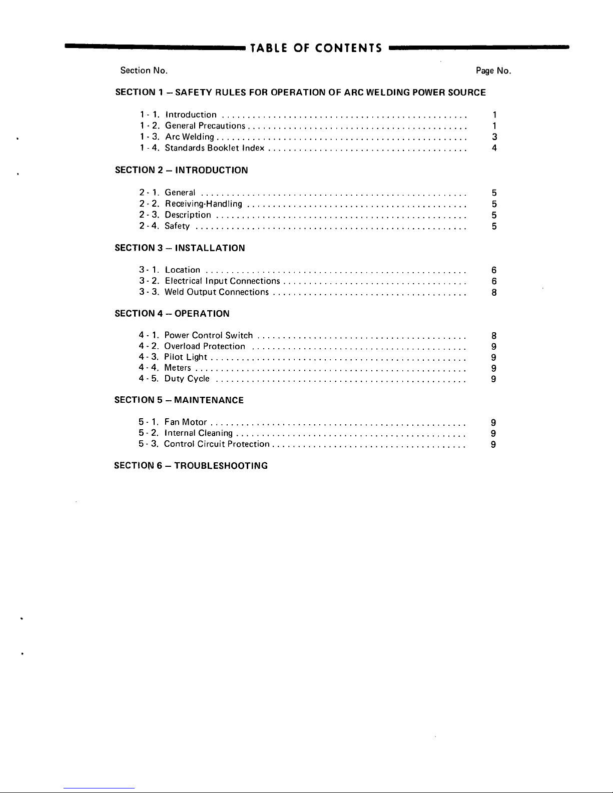
TABLE
OF
CONTENTS
Section
No.
Page
No.
SECTION
1
SAFETY
RULES
FOR
OPERATION
OF
ARC
WELDING
POWER
SOURCE
1
-
1.
Introduction
1
1
-
2.
General
Precautions
1
1
-
3.
Arc
Welding
3
1
-
4.
Standards
Booklet
Index
4
SECTION
2
INTRODUCTION
2-1.
General
5
2
-
2.
Receiving-Handling
5
2-
3.
Description
5
2-4.
Safety
5
SECTION
3INSTALLATION
3-1.
Location
6
3-
2.
Electrical
Input
Connections
6
3-
3.
Weld
Output
Connections
8
SECTION
4
OPERATION
4-
1.
Power
Control
Switch
8
4
-
2.
Overload
Protection
9
4-3.
Pilot
Light
9
4-4.
Meters
9
4
-
5.
Duty
Cycle
9
SECTION
5
MAINTENANCE
5-1.
FanMotor
9
5-
2.
Internal
Cleaning
9
5
-
3.
Control
Circuit
Protection
9
SECTION
6
TROUBLESHOOTING

SECTION
1-SAFETY
RULES
FOR
OPERATION
OF
ARC
WELDING
POWER
SOURCE
1-1.
INTRODUCTION
We
learn
by
experience.
Learning
safety
through
personal
experience,
like
a
child
touching
a
hot
stove
is
harmful,
wasteful,
and
unwise.
Let
the
experience
of
others
teach
you.
Safe
practices
developed
from
experience
in
the
use
of
weld
ing
and
cutting
are
described
in
this
manual.
Research,
devel
opment,
and
field
experience
have
evolved
reliable
equipment
and
safe
installation,
operation,
and
servicing
practices.
Acci
dents
occur
when
equipment
is
improperly
used
or
main
tained.
The
reason
for
the
safe
practices
may
not
always
be
given.
Some
are
based
on
common
sense,
others
may
require
technical
volumes
to
explain.
It
is
wiser
to
follow
the
rules.
Read
and
understand
these
safe
practices
before
attempting
to
install,
operate,
or
service
the
equipment.
Comply
with
these
procedures
as
applicable
to
the
particular
equipment
used
and
their
instruction
manuals,
for
personal
safety
and
for
the
safety
of
others.
Failure
to
observe
these
safe
practices
may
cause
serious
in
jury
or
death.
When
safety
becomes
a
habit,
the
equipment
can
be
used
with
confidence.
These
safe
practices
are
divided
into
two
Sections:
1
-
General
Precautions,
common
to
arc
welding
and
cutting;
and
2
.
Arc
Welding
(and
Cutting)(only).
Reference
standards:
Published
Standards
on
safety
are
also
available
for
additional
and
more
complete
procedures
than
those
given
in
this
manual.
They
are
listedinthe
Standards
Indexinthis
manual.
ANSI
Z49.1
is
the
most
complete.
The
National
Electrical
Code,
Occupational
Safety
and
Health
Administration,
local
industrial
codes,
and
local
in
spection
requirements
also
provide
a
basis
for
equipment
in
stallation,
use,
and
service.
GENERAL
PRECAUTIONS
Burn
Prevention
Wear
protective
clothing
-
leather
(or
asbestos)
gauntlet
gloves,
hat,
and
high
safety-toe
shoes.
Button
shirt
collar
and
pocket
flaps,
and
wear
cuffless
trousers
to
avoid
entry
of
sparks
and
slag.
Wear
helmet
with
safety
goggles
or
glasses
with
side
shields
underneath,
appropriate
filter
lenses
or
plates
(protected
by
clear
cover
glass).This
is
a
MUST
for
welding
or
cutting,
(and
chipping)
to
protect
the
eyes
from
radiant
energy
and
flying
metal.
Replace
cover
glass
when
broken,
pitted,
or
spattered.
See
1-3A.2.
Avoid
oily
or
greasy
clothing.Aspark
may
ignite
them.
Hot
metal
such
as
electrode
stubs
and
workpieces
should
never
be
handled
without
gloves.
Medical
first
aid
and
eye
treatment.
First
aid
facilities
and
a
qualified
first
aid
person
should
be
available
for
each
shift
unless
medical
facilities
are
close
by
for
immediate
treatment
of
flash
burns
of
the
eyes
and
skin
burns.
Ear
plugs
should
be
worn
when
working
on
overhead
or
in
a
confined
space.
A
hard
hat
should
be
worn
when
others
work
overhead.
Flammable
hair
preparations
should
not
be used
by
persons
intending
to
weld
or
cut.
B.
Toxic
Fume
Prevention
Adequate
ventilation.
Severe
discomfort,
illness
or
death
can
result
from
fumes,
vapors,
heat
or
oxygen
enrichment
or
depletion
that
welding
(or
cutting)
may
produce.
Prevent
them
with
adequate
ventilation
as
described
in
ANSI
Stan
dard
Z49.1
listed
1
in
Standards
index.
NEVER
ventilate
with
oxygen.
Lead
-,
cadmium
-,
zinc
-,
mercury
-,
and
beryllium
-
bearing
and
similar
materials,
when
welded
(or
cut)
may
produce
harmful
concentrations
of
toxic
fumes.
Adequate
local
exhaust
ventilation
must
be
used,
or
each
person
in
the
area
as
well
as
the
operator
must
wear
an
air-supplied
respirator.
For
beryllium,
both
must
be
used.
Metals
coated
with
or
containing
materials
that
emit
toxic
fumes
should
not
be
heated
unless
coating
is
removed
from
the
work
surface,
the
area
is
well
ventilated,
or
the
operator
wears
an
air-supplied
respirator.
Work
in
a
confined
space
only
while
it
is
being
ventilated
and,
if
necessary,
while
wearing
an
air-supplied
respirator.
Gas
leaks
in
a
confined
space
should
be
avoided.
Leaked
gas
in
large
quantities
can
change
oxygen
concentration
danger
ously.
Do
not
bring
gas
cylinders
into
a
confined
space.
Leaving
confined
space,
shut
OFF
gas
supply
at
source
to
prevent
possible
accumulation
of
gases
in
the
space
if
down
stream
valves
have
been
accidently
opened
or
left
open.
Check
so
be
sure
that
the
space
is
safe
before
re-entering
it.
Vapors
from
chlorinated
solvents
can
be
decomposed
by
the
heat
of
the
arc
(or
flame)
to
form
PHOSGENE,
a
highly
toxic
gas,
and
other
lung
and
eye
irritating
products.
The
ultra
violet
Iradiant)
energy
of
the
arc
can
also
decompose
sri
chloroethylene
and
perchloroethylene
vapors
to
form
phos
gene.
DO
NOT
WELD
or
cut
where
solvent
vapors
can
be
drawn
into
the
welding
or
cutting
atmosphere
or
where
the
radiant
energy
can
penetrate
so
atmospheres
containing
even
minute
amounts
of
trichloroethylene
or
perchloroethylene.
C.
Fire
and
Explosion
Prevention
Causes
of
fire
and
explosion
are:
combustibles
reached
by
the
arc,
flame,
flying
sparks,
hot
slag
or
heated
material;
misuse
of
compressed
gases
and
cylinders;
and
short
circuits.
BE
AWARE
THAT
flying
sparks
or
falling
slag
can
pass
through
cracks,
along
pipes,
through
windows
or
doors,
and
through
wall
or
floor
openings,
out
of
sighs
of
the
goggled
operator.
Sparks
and
slag
can
fly
35
feet.
To
prevent
fires
and
explosion:
Keep
equipment
clean
and
operable,
free
of
oil,
grease,
and
(in
electrical
parts)
of
metallic
particles
that
can
cause
short
circuits.
If
combustibles
are
in
area,
do
NOT
weld
or
cut.
Move
the
work
if
practicable,
to
an
area
free
of
combustibles.
Avoid
paint
spray
rooms,
dip
tanks,
storage
areas,
vensilators.
If
she
work
cannot
be
moved,
move
combustibles
at
least
35
fees
away
out
of
reach
of
sparks
and
heat;
or
prosect
against
ignition
wish
suitable
and
snug-fitting,
fire-resistant
covers
or
shields.
Walls
touching
combustibles
on
opposite
sides
should
not
be
welded
on
(or
cut).
Walls,
ceiiings,
and
floor
near
work
should
be
protected
by
heat-resistant
covers
or
shields.
Fire
watcher
must
be
standing
by
with
suitable
fire
ex
tinguishing
equipment
during
and
for
some
time
after
weld
ing
or
cutting
if:
a.
appreciable
combustibles
(including
building
construc
tion)
are
within35fees
b.
appreciable
combustibles
are
further
than
35
feet
but
can
be
ignited
by
sparks
c.
openings
(concealed
or
visible)
in
floors
or
walls
within
35
feet
may
expose
combustibles
to
sparks
d.
combustibles
adjacent
so
walls,
ceilings,
roofs,
or
metal
partitions
can
be
ignited
by
radiant
or
conducted
heat.
Hot
work
permit
should
be
obtained
before
operation
to
ensure
supervisors
approval
that
adequate
precautions
have
been
taken.
After
work
is
done,
check
that
area
is
free
of
sparks,
glowing
embers,
and
flames.
An
empty
container
that
held
combustibles,
or
that
can
pro
duce
flammable
or
toxic
vapors
when
heated,
muss
never
be
welded
on
or
cut,
unless
container
has
first
been
cleaned
as
described
in
AWS
Standard
A6.O.
listed
3
in
Standards
index.
1-2.
A.
OM-267
Page
1
This
includes:
a
thorough
steam
or
caustic
cleaning
(or.
a
solvent
or
water
washing,
depending
on
the
combustibles
solubilityl
followed
by
purging
and
inerting
with
nitrogen
or
carbon
dioxide,
and
using
protective
equipment
as
recom
mended
in
A6.0.
Waterfilling
just
below
working
level
may
substitute
for
inerting.
A
container
with
unknown
conten~
should
be
cleaned
(see
paragraph
above).
Do
NOT
depend
on
sense
of
smell
or
sight
to
determineifitissafetoweld
or
cut.
Hollow
castings
or
containers
must
be
vented
before
welding
or
cutting.
They
can
explode.
Explosive
atmospheres.
Never
weld
or
cut
where
the
air
may
contain
flammable
dust,
gas,
or
liquid
vapors
(such
as
gaso
line).
D.
Compressed
Gas
Equipment
Standard
precautions.
Comply
with
Drecautions
in
this
manual,
and
those
detailed
in
CGA
Standard
P-i,
PRECAU
TIONS
FOR
SAFE
HANDLING
OF
COMPRESSED
GASES
IN
CYLINDERS,
listed
6inStandards
index.
1.
Pressure
Regulators
Regulator
relief
valve
is
designed
to
protect
only
the
regula
tor
from
overpressure;
it
is
not
intended
to
protect
any
downstream
equipment.
Provide
such
protection
with
one
or
more
relief
devices.
Never
connect
a
regulator
to
a
cylinder
containing
gas
other
than
that
for
which
the
regulator
was
designed.
Remove
faulty
regulator
from
service
immediately
for
repair
)first
close
cylinder
valve).
The
following
symptoms
indicate
a
faulty
regulator:
Leaks
-
if
gas
leaks
externally.
Excessive
Creep
-
if
delivery
pressure
continues
so
rise
with
downstream
valve
closed.
Faulty
Gauge
-
if
gauge
pointer
does
not
move
off
stop
pin
when
pressurized,
nor
returns
to
stop
pin
after
pressure
release.
Repair.
Do
NOT
attempt
repair.
Send
faulty
regulators
for
repair
to
manufacturers
designated
repair
center,
where
special
techniques
and
tools
are
usedbytrained
personnel.
2.
Cylinders
Cylinders
must
be
handled
carefully
to
prevent
leaks
and
damage
to
their
walls,
valves,
or
safety
devices:
Avoid
electrical
circuit
contact
with
cylinders
including
third
rails,
electrical
wires,
or
welding
circuits.
They
can
produce
short
circuit
arcs
that
may
lead
to
a
serious
accident.
(See
1-3C.)
ICC
or
DOT
marking
must
be
on
each
cylinder.
It
is
an
assurance
of
safety
when
the
cylinder
is
properly
handled.
Identifying
gas
content.
Use
only
cylinders
wish
name
of
gas
marked
on
them;
do
not
rely
on
color
to
identify
gas
con
tent.
Notify
supplier
if
unmarked.
NEVER
DEFACE
or
alter
name,
number,
or
other
markings
on
a
cylinder.
It
is
illegal
and
hazardous.
Empties:
Keep
valves
closed,
replace
caps
securely;
mark
MT;
keep
them
separate
from
FULLS
and
return
promptly.
Prohibited
use.
Never
use
a
cylinder
or
its
contents
for
other
than
its
intended
use,
NEVER
as
a
support
or
roller.
Locate
or
secure
cylinders
so
they
cannot
be
knocked
over.
Passageways
and
work
areas.
Keep
cylinders
clear
of
areas
where
they
may
be
struck.
Transporting
cylinders.
With
a
crane,
useasecure
support
such
as
a
platform
or
cradle.
Do
NOT
lift
cylinders
off
the
ground
by
their
valves
or
caps,
or
by
chains,
slings,
or
mag
nets.
Do
NOT
expose
cylinders
to
excessive
heat,
sparks,
slag,
and
flame,
etc.
that
may
cause
rupture.
Do
not
allow
contents
to
exceed
130F.
Cool
with
water
spray
where
such
exposure
exists.
Protect
cylinders
particularly
valves
from
bumps,
falls,
falling
objects,
and
weather.
Replace
caps
securely
when
moving
cylinders.
Stuck
valve.
Do
NOT
use
a
hammer
or
wrench
to
open
a
cylinder
valve
that
can
not
be
opened
by
hand.
Notify
your
supplier.
Mixing
gases.
Never
try
to
mix
any
gases
in
a
cylinder.
Never
refill
any
cylinder.
Cylinder
fittin~
should
never
be
modified
or
exchanged.
3.
Hose
Prohibited
use.
Never
use
hose
other
than
that
designed
for
the
specified
gas.
A
general
hose
identification
rule
is:
red
for
fuel
gas,
green
for
oxygen,
and
black
for
inert
gases.
Use
ferrules
or
clamps
designed
for
the
hose
(not
ordinary
wire
or
other
substitute)
as
a
binding
to
connect
hoses
to
fittings.
No
copper
tubing
splices.
Use
only
standard
brass
fittings
to
splice
hose.
Avoid
long
runs
to
prevent
kinks
and
abuse.
Suspend
hose
off
ground
to
keep
it
from
being
run
over,
stepped
on,
or
other
wise
damaged.
Coil
excess
hose
to
prevent
kinks
and
tangles.
Protect
hose
from
damage
by
sharp
edges,
and
by
sparks,
slag,
and
open
flame.
Examine
hose
regularly
for
leaks,
wear,
and
loose
connec
tions.
Immerse
pressured
hose
in
water;
bubbles
indicate
leaks.
Repair
leaky
or
worn
hose
by
cutting
area
out
and
splicing
(1-2D3(.
Do
NOT
use
tape.
4.
Proper
Connections
Clean
cylinder
valve
outlet
of
impurities
that
may
clog
orifices
and
damage
seats
before
connecting
regulator.
Except
for
hydrogen,
crack
valve
momentarily,
pointing
outlet
away
from
people
and
sources
of
ignition.
Wipe
withaclean
lint-
less
cloth.
Match
regulatortocylinder.
Before
connecting,
check
that
the
regulator
label
and
cylinder
marking
agree,
and
that
the
regulator
inlet
and
cylinder
outlet
match.
NEVER
CON
NECT
a
regulator
designed
for
a
particular
gasorgases
to
a
cylinder
containing
any
other
gas.
Tighten
connections.
When
assembling
threaded
connections,
clean
and
smooth
seats
where
necessary.
Tighten.
If
connec
tion
leaks,
disassemble,
clean,
and
retighten
using
properly
fitting
wrench.
Adapters.
Use
a
CGA
adapter
(available
from
your
supplier)
between
cylinder
and
regulator,
if
one
is
required.
Use
two
wrenches
to
tighten
adapter
marked
RIGHT
and
LEFT
HAND
threads.
Regulator
outlet
(or
hose)
connections
may
be
identified
by
right
hand
threads
for
oxygen
and
left
hand
threads
(with
grooved
hex
on
nut
or
shank)
for
fuel
gas.
5
Pressurizing
Steps:
Drain
regulator
of
residual
gas
through
suitable
vent
before
opening
cylinder
(or
manifold
valve)
by
turning
adjusting
screw
in
(clockwise).
Draining
prevents
excessive
compression
heat
at
high
pressure
seat
by
allowing
seat
to
open
on
pressur
ization.
Leave
adjusting
screw
engaged
slightlyonsingle-stage
regulators.
Stand
to
side
of
regulator
while
opening
cylinder
valve.
Open
cylinder
valve
slowly
so
that
regulator
pressure
in
creases
slowly.
When
gauge
is
pressurized
(gauge
reaches
regu
lator
maximum)
leave
cylinder
valve
in
following
position:
For
oxygen,
and
inert
gases,
open
fully
to
seal
stem
against
possible
leak.
For
fuel
gas,
open
to
less
than
one
turn
to
permit
quick
emergency
shutoff.
Pa~
2
Use
pressure
charts
(available
from
your
supplier)
for
safe
and
efficient,
recommended
pressure
settingsonregulators.
Check
for
leaks
on
first
pressurization
and
regularly
there
after.
Brush
with
soap
solution
(capful
of
Ivory
Liquid
or
equivalent
per
gallon
of
water).
Bubbles
indicate
leak.
Clean
off
soapy
water
after
test;
dried
soap
is
combustible.
E.
User
Responsibilities
Remove
leaky
or
defective
equipment
from
service
immed
iately
for
repair.
See
User
Responsibility
statement
in
equip
ment
manual.
F.
Leaving
Equipment
Unattended
Close
gas
supply
at
source
and
drain
gas.
G.
Rope
Staging-Support
Rope
staging-support
should
not
be
used
for
welding
or
cut
ting
operation;
rope
may
burn.
1-3.
ARC
WELDING
Comply
with
precautions
in
1-1,
1-2.
and
this
section.
Arc
Welding,
properly
done,
is
a
safe
process,
but
a
careless
opera
tor
invites
trouble.
The
equipment
carries
high
currents
at
significant
yoltages.
The
arc
is
very
bright
and
hot.
Sparks
fly,
fumes
rise,
ultraviolet
and
infrared
energy
radiates,
weld
ments
are
hot,
and
compressed
gases
may
be
used.
The
wise
operator
avoids
unnecessary
risks
and
protects
himself
and
others
from
accidents.
Precautions
are
described
here
and
in
.standards
referenced
in
index.
A.
Burn
Protection
Comply
with
precautions
in
1-2.
The
welding
arc
is
intense
and
visibly
bright.
Its
radiation
can
damage
eyes,
penetrate
lightweight
clothing,
reflect
from
light-colored
surfaces,
and
burn
the
skin
and
eyes.
Skin
burns
resemble
acute
sunburn,
those
from
gas-shielded
arcs
are
more
severe
and
painful.
DONT
GET
BURNED;
COMPLY
WITH
PRECAUTIONS.
1.
Protective
Clothing
Wear
long-sleeve
clothing
(particularly
for
gas-shielded
arc)
in
addition
to
gloves,
hat,
and
thoes
(1-2A(.
As
necessary,
use
additional
protective
clothing
such
as
leather
jacket
or
sleeves,
flame-proof
apron,
and
fire-resistant
leggings.
Avoid
outergarments
of
untreated
cotton.
Bare
skin
protection.
Wear
dark,
substantial
clothing.
Button
collar
to
protect
chest
and
neck
and
button
pockets
to
pre
vent
entry
of
sparks.
2.
Eye
and
Head
Protection
Protect
eyes
from
exposure
to
arc.
NEVER
look
at
an
elec
tric
arc
without
protection.
Welding
helmet
or
shield
containing
a
filter
plate
shade
no.
12
or
denser
must
be
used
when
welding.
Place
over
face
before
striking
arc.
Protect
filter
plate
withaclear
cover
plate.
Cracked
or
broken
helmet
or
shield
should
NOT
be
worn;
radiation
can
pass
through
to
cause
burns.
Cracked,
broken,
or
loose
filter
plates
must
be
replaced
IM
MEDIATELY.
Replace
clear
cover
plate
when
broken,
pitted,
or
spattered.
Flash
goggles
with
side
shields
MUST
be
worn
under
the
helmet
to
give
some
protection
to
the
eyes
should
the
helmet
not
be
lowered
over
the
face
before
an
arc
is
struck.
Looking
at
an
arc
momentarily
with
unprotected
eyes
(particularly
a
high
intensity
gas-shielded
arc)
can
cause
a
retinal
burn
that
may
leave
a
permanent
dark
area
in
the
fieldofvision.
3.
Protection
of
Nearby
Personnel
Enclosed
welding
area.
For
production
welding,
a
separate
room
or
enclosed
bay
is
best.
In
open
areas,
surround
the
operation
with
low-reflective,
non-combustible
screens
or
panels.
Allow
for
free
air
circulation,
particularly
at
floor
level.
Viewing
the
weld.
Provide
face
shields
for
all
persons
who
will
be
looking
directly
at
the
weld.
Others
working
in
area.
See
that
all
persons
are
weanng
flash
goggles.
Before
starting
to
weld,
make
sure
that
screen
flaps
or
bay
doors
are
closed.
B.
Toxic
Fume
Prevention
Comply
with
precautions
in
1-2B.
Generator
engine
exhaust
must
be
vented
to
the
outside
air.
Carbon
monoxide
can
kill.
C.
Fire
and
Explosion
Prevention
Comply
with
precautions
in
1-2C.
Equipments
rated
capacity.
Do
not
overload
arc
welding
equipment.
It
may
overheat
cables
and
cause
a
fire.
Loose
cable
connections
may
overheat
or
flash
and
cause
a
fire.
Never
strike
an
arcona
cylinderorother,pressure
vessel.
It
creases
a
brittle
area
that
can
cause
a
violent
rupture
or
lead
to
such
a
rupture
laser
under
rough
handling.
D.
Compressed
Gas
Equipment
Comply
wish
precautions
in
1-2D.
E.
Shock
Prevention
Exposed
hot
conductors
or
other bare
metal
in
the
welding
circuit,
or
in
ungrounded,
electrically-HOT
equipment
can
fatally
shock
a
person
whose
body
becomes
a
conductor.
DO
NOT
STAND,
SIT, LIE,
LEAN
ON,
OR
TOUCH
a
wet
sur
face
when
welding,
without
suitable
protection.
To
protect
against
shock:
Keep
body
and
clothing
dry.
Never
work
in
damp
area
with
out
adequate
insulation
against
electrical
shock.
Stay
on
a
dry
duckboard,
or
rubber
mat
when
dampness
or
sweat
can
not
be
avoided.
Sweat,
sea
water,
or
moisture
between
body
and
an
electrically
HOT
pars
-
or
grounded
metal
-
reduces
the
body
surface
electrical
resistance,
enabling
dangerous
and
possibly
lethal
currents
to
flow
through
the
body.
1.
Grounding
the
Equipment
When
installing,
connect
the
frames
of
each
unit
such
as
welding
power
source,
control,
work
table,
and
water
circula
tor
to
she
building
ground.
Conductors
must
be
adequate
so
carry
ground
currents
safely.
Equipment
made
electrically
HOT
by
stray
current
may
shock,
possibly
fatally.
Do
NOT
GROUND
to
electrical
conduit,
ortoa
pipe
carrying
ANY
gas
or
a
flammable
liquid
such
as
oilorfuel.
Three-phase
connection.
Check
phase
requirement
of
equip
ment
before
installing.
If
only
3-phase
power
is
available,
connect
single-phase
equipment
so
only
two
wiresofthe
3-phase
line.
Do
NOT
connect
the
equipment
ground
lead
to
the
third
(live)
wire,
or
the
equipment
will
become
electri
cally
HOT
-
a
dangerous
condition
that
can
shock,
possibly
fatally.
Before
welding,
check
ground
for
continuity.
Be
sure
conduc
tors
are
touching
bare
metal
of
equipment
frames
at
connec
tions.
If
a
line
cord
with
a
ground
lead
is
provided
with
she
equip
ment
for
connection
to
a
switchbox,
connect
the
ground
lead
to
the
grounded
switchbox.
If
a
three-prong
plug
is
added
for
connection
to
a
grounded
mating
receptacle,
the
ground
lead
must
be
connected
so
the
ground
prong
only.
If
the
line
card
comes
with
a
three-prong
plug,
connect
to
a
grounded
mating
receptacle.
Never
remove
she
ground
prong
from
a
plug,
or
use
a
plug
wishabroken
off
ground
prong.
Trademark
of
Proctor
&
Gamble.
OM-267
Page
3
 Loading...