

Miller Gold Star 500SSX Owner's Manual
Miller
Apri
1994
Form:
OM-168
256
Effective
With
Serial
No.
KE600689
OWNERS
MANUAL
Read
and
follow
these
instructions
and
all
safety
blocks
carefully.
Have
only
trained
and
qualified
persons
install,
operate,
or
service
this
unit.
Call
your
distributor
if
you
do
not
understand
the
directions.
Gold
Starfi
500SSX
CC/DC
Welding
Power
Source
For
SMAW
and
GTAW
Welding
510
Amperes,
41
Volts
DC,
At
35%
Duty
Cycle
Requires
Three-Phase,
50/60
Hz
Input
Power
Overheating
Protection
Arc
(Dig)
Control
Give
this
manualtothe
operator.
For
help,
call
your
distributor
or:
MILLER
Electric
Mfg.
Co.,
P.O.
Box
1079,
Appleton,
WI
54912
414-734-9821
cover
1/94
ST-cOO
599-H
'
1994
MILLER
Electric
Mfg.
Co.
PRINTEDINUSA

MILLERS
TRUE
BLUETM
LIMITED
WARRANTY
Effective
,Janu
ary
1,
1992
(Equipment
with
a
serial
number
preface
of
KC
or
newer)
This
limited
warranty
supersedes
all
previous
MtLLER
warranties
andisevr:tusive
with
no
other
guarantees
or
warranties
espreasedorimptied.
LtMITED
WARRANTY
Subject
to
the
terms
and
coeditione
betow,
MtLLER
Electric
Mtg.
Co
.
Appleton,
Wisconsin,
warrants
to
its
original
retail
purchaser
that
new
MILLER
equipment
sotd
after
the
effective
dateofthis
limited
warranty
is
tree
of
de
tects
in
materiat
and
workmanship
at
the
time
it
is
shipped
by
MtLLER
THtS
WAR
RANTY
IS
EXPRESSLY
tN
LIEU
OF
ALL
OTHER
WARRANTIES.
EXPRESS
OR
tMPLtED.
INCLUDtNG
THE
WARRANTIES
OF
MERCHANTABILITY
AND
FIT
NESS.
Within
the
warranty
periods
listed
below.
MILLER
will
repair
or
replace
any
war
raeted
parts
or
components
that
fail
due
to
suck
defects
in
material
or
workmanship.
MILLER
must
be
notified
in
writing
within
thirty
(30)
days
of
such
detectorfailure,
at
which
lime
MILLER
will
provide
instructions
on
the
warranty
claim
procedures
to
be
followed.
MILLER
shall
honor
warranty
claims
on
warranted
equipment
listed
belowinthe
event
of
suchafailure
within
the
warranty
time
periods
Alt
warranty
time
periods
start
on
the
date
that
the
equipment
was
delivered
to
the
original
retail
purchaser.
or
one
year
ahei
Ike
equipment
is
sent
to
the
distributor
5
Years
Parts
3
Years Labor
*
Original
main
power
rectihers
2.
3
YearsParts
and
Labor
Transformer/Rectiher
Power
Sources
*
Plasma
Arc
Cuaing
Power
Sources
Semi-Automatic
and
Automatic
Wire
Feeders
*
Robots
3 2
Years
Parts
and
Labor
*
Engine
Driven
Welding
Generators
(NOTE
Engines
are
warranted
separately
by
the
engine
manufacturer
for
a
period
of
Iwo
years.)
*
Air
Compressors
4.
1
YearParts
and
Labor
*
Motor
Driven
Guns
*
Process
Controllers
Water
Coolant
Systems
*
HF
Units
*
Grids
*
Spot
Welders
*
Load
Banks
*
SDX
Transformers
*
Running
Gear/Trailers
Field
Options
(NOTE
Field
options
are
covered
under
True
EluenM
for
the
remaining
warranty
period
of
the
product
they
are
installed
in,
orbra
minimum
of
one
year
whichever
is
greater
I
6
Months
Batteries
90
Days
Parts
and
Labor
*
MIG
Guns/TIG
Torches
Plasma
Cutting
Torches
1
*
Remote
Controls
Accessory
Kits
Replacement
Parts
MILLERS
True
BluerM
Limited
Warranty
shall
not
apply
to:
I
Items
furnished
by
MILLER,
but
manufactured
by
others,
suck
as
ehgines
or
trade
accessories.
These
items
are
coveredbythe
manufacturers
warranty,
if
any
2
Consumable
components:
such
as
contact
rips,
cuEing
nozzles.
confactore
avd
relays
or
parts
Ihet
fail
duels
normal
wear.
3
Equipment
that
has
been
modified
by
any
party
other
than
MILLER.
or
equip
ment
Ihat
has
been
improperly
installed,
improperly
operated
or
misused
based
upon
industry
standards,
or
equipment
which
has
not
had
reasonable
and
necessary
maintenance,
or
equipment
which
has
been
used
for
operation
outside
of
the
specifications
for
the
equipment.
MILLER
PRODUCTS
ARE
INTENDED
FOR
PURCHASE
AND
USEBYCOMMER
CIAL/INDUSTRIAL
USERS
AND
PERSONS
TRAINED
AND
EXPERIENCED
IN
THE
USE
AND
MAINTENANCE
OF
WELDING
EQUIPMENt
In
the
event
of
a
warranty
claim
coveredbythis
warranty,
the
exclusive
remedies
skull
be.
at
MILLERS
option.
11)
repair.
or
(2)
replacement:
or,
where
authorized
in
writing
by
MILLER
in
appropriate
cases,
(3)
the
reasonable
costof
repair
or
replace
ment
alan
authorized
MILLER
service
station:
or
(4)
payment
of
or
credit
for
the
pur
chase
price
(less
reasonable
depreciation
based
upon
actual
use)
upon
return
of
the
goods
at
customers
risk
and
espense.
MtLLERS
option
of
repairorreplacement
will
beFOB
FactoryatAppleton,
Wisconsin.orFOB.
eta
MILLER
authorized
ser
vice
facility
as
determined
by
MILLER
Therefore
no
compensation
or
reimburse
ment
br
Iransportafion
costs
of
any
kind
will
be
allowed.
TO
THE
EXTENT
PERMITTED
BY
LAW.
THE
REMEDIES
PROVIDED
HEREfN
ARE
THE
SOLE
AND
EXCLUSIVE
REMEDIES.INNO
EVENT
SHALL
MILLER
BE
LIABLE
FOR
DIRECT
INDIRECT.
SPECIAL.
INCIDENTAL
OR
CONSEQUENTIAL
DAMAGES
IINCLUDING
LOSS
OF
PROFIT),
WHETHER
BASED
ON
CON
TRACT
TORT
OR
ANY
OTHER
LEGAL
THEORY
ANY
EXPRESS
WARRANTY
NOT
PROVIDED
HEREIN
AND
ANY
IMPLIED
WAR
RANTY.
GUARANTY
OR
REPRESENTATION
ASTO
PERFORMANCE.
ANDANY
REMEDY
FOR
BREACH
OF
CONTRACT
TORT
OR
ANY
OTHER
LEGAL
THEORY
WHICH.
BUT
FOR
THIS
PROVISION.
MIGHT
ARISE
BY
IMPLICATION,
OPERATION
OF
LAW.
CUSTOM
OF
TRADE
OR
COURSE
OF
DEALING.
IN
CLUDING
ANY
IMPLIED
WARRANTY
OF
MERCHANTABILITY
OR
FITNESS
FOR
PARTICULAR
PURPOSE,
WITH
RESPECT
TO
ANY
AND
ALL
EQUIPMENT
FURNISHED
BY
MILLER
IS
EXCLUDED
AND
DISCLAIMED
BY
MILLER.
Some
states
in
the
U.S.A
do
not
allow
limitationsofhow
long
an
implied
warranty
lasts.
or
the
euclusiori
of
incidental.
indirect.
special
or
consequential
damages,
so
the
above
limitation
or
evclusion
may
not
apply
to
you.
This
warranty
provides
spe
cilic
legal
rights,
and
other
rights
may
be
available,
but
may
vary
from
state
10
slate.
In
Canada,
legislation
in
some
provinces
provides
for
certain
additional
warranties
or
remedies
other
than
as
staled
herein,
and
10
the
eefenf
that
they
may
not
be
waived,
the
limitations
and
esclusions
set
out
above
may
nor
apply.
This
Limited
Warranty
provides
specific
legal
rights,
and
of
her
rights
maybe
available,
but
may
vary
from
province
to
province.
I
J
7S~>
~.
~-1
S
S
B.
R
EC
EIVI
NG-HAN
D
LING
Before
unpacking
equipment,
check
carton
for
any
damage
that
may
have
occurred
dur)ng
shipment.
File
any
claims
for
loss
or
damage
with
the
delivering
carrier.
Assistance
for
filing
or
settling
claims
may
be
Qbta)ned
trom
distributor
and/or
equ)pment
manufacturers
Transportation
Department.
When
requesting
)nformation
about
this
equipment,
always
provide
Mctdel
Designation
and
Serial
or
Style
Number.
Use
the
following
spaces
to
record
Model
Designation
and
Serial
or
Style
Number
of
your
unit.
The
information
is
located
on
the
ratin9
label
or
nameplate,
Model
__________
Serial
or
Style
No.
DateofPurchase
miller
9/93

ARC
WELDING
SAFETY
PRECAUTIONS
5.
Properly
install
and
ground
this
equipment
according
to
its
Owners
Manual
and
national,
state,
and
local
codes.
6.
When
making
input
connections,
attach
proper
grounding
conductor
first.
7.
Turn
off
all
equipment
when
not
in
use.
8.
Do
not
use
worn,
damaged,
undersized,
or
poorly
spliced
cables.
9.
Do
not
wrap
cables
around
your
body.
10.
Ground
the
workpiece
to
a
good
electrical
(earth)
ground.
11.
Do
not
touch
electrode
if
in
contact
with
the
work
or
ground.
12.
Use
only
well-maintained
equipment.
Repair
or
replace
damaged
parts
at
once.
13.
Wear
a
safety
harness
if
working
above
floor
level.
14.
Keep
all
panels
and
covers
securely
in
place.
a
WARNING
ARC
WELDING
can
be
hazardous.
PROTECT
YOURSELF
AND
OTHERS
FROM
POSSIBLE
SERIOUS
INJURY
OR
DEATH.
KEEP
CHILDREN
AWAY.
PACEMAKER
WEARERS
KEEP
AWAY
UNTIL
CONSULTING
YOUR
DOCTOR.
In
welding,
as
in
most
jobs,
exposure
to
certain
hazards
occurs.
Welding
is
safe
when
precautions
are
taken.
The
safety
information
given
below
is
only
a
summary
of
the
more
complete
safety
information
that
will
be
found
in
the
Safety
Standards
listedonthe
next
page.
Read
and
follow
all
Safety
Standards.
HAVE
ALL
INSTALLATION,
OPERATION,
MAINTENANCE,
AND
REPAIR
WORK
PERFORMED
ONLY
BY
QUALIFIED
PEOPLE.
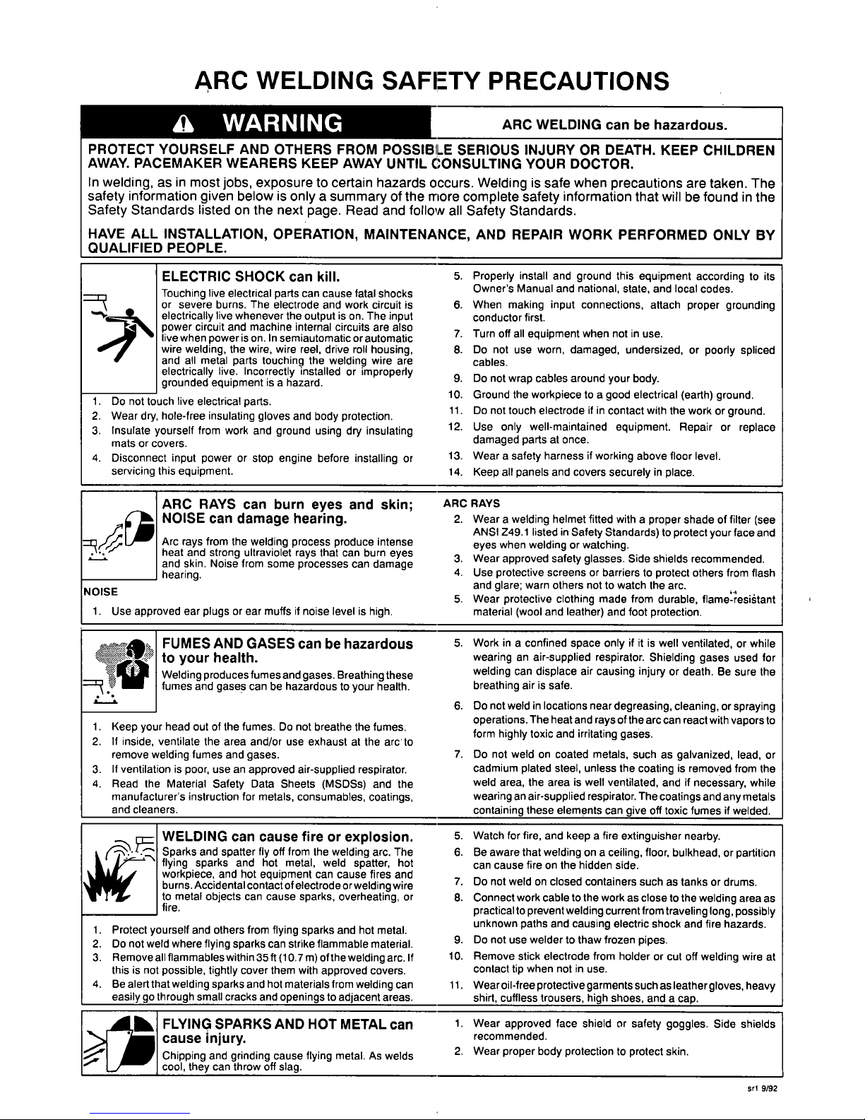
ELECTRIC
SHOCK
can
kill.
Touching
live
electrical
parts
can
cause
fatal
shocks
or
severe
burns.
The
electrode
and
work
circuit
is
electrically
live
whenever
the
output
is
on.
The
input
power
circuit
and
machine
internal
circuits
are
also
live
when
power
is
on.
In
semiautomatic
or
automatic
wire
welding,
the
wire,
wire
reel,
drive
roll
housing,
and
all
metal
parts
touching
the
welding
wire
are
electrically
live.
Incorrectly
installed
or
improperly
grounded
equipment
is
a
hazard.
1.
Do
not
touch
live
electrical
parts.
2.
Wear
dry,
hole-free
insulating
gloves
and
body
protection.
3.
Insulate
yourself
from
work
and
ground
using
dry
insulating
mats
or
covers.
4.
Disconnect
input
power
or
stop
engine
before
installing
or
servicing
this
equipment.
ARC
RAYS
can
burn
eyes
and
skin;
ARC
RAYS
~
NOISE
can
damage
hearing.
2.
Wear
a
welding
helmet
fitted
with
a
proper
shade
of
filter
(see
ANSI
Z49.1
listed
in
Safety
Standards)
to
protect
your
face
and
Arc
rays
from
the
welding
process
produce
intense
eyes
when
weldingorwatching.
heat
and
strong
ultraviolet
rays
that
can
burn
eyes
3.
Wear
approved
safety
glasses.
Side
shields
recommended.
and
skin.
Noise
from
some
processes
can
damage
hearing.
4.
Use
protective
screens
or
barriers
to
protect
others
from
flash
and
glare;
warn
others
not
to
watch
the
arc.
NOISE
5.
Wear
protective
clothing
made
from
durable,
fIame-resi~tant
1.
Use
approved
ear
plugs
or
ear
muffs
if
noise
level
is
high.
material
(wool
and
leather)
and
foot
protection.
FUMES
AND
GASES
can
be
hazardous
5.
Work
in
a
confined
space
only
if
it
is
well
ventilated,
or
while
~
to
your
health.
wearing
an
air-supplied
respirator.
Shielding
gases
used
for
Q
Welding
producesfumes
and
gases.
Breathing
these
welding
can
displace
air
causing
injury
or
death.
Be
sure
the
fumes
and
gases
can
be
hazardous
to
your
health.
breathing
airissafe.
6.
Do
not
weldinlocations
near
degreasing,
cleaning,
or
spraying
operations.
The
heat
and
rays
of
the
arc
can
react
with
vapors
to
1.
Keep
your
head
out
of
the
fumes.
Do
not
breathe
the
fumes,
form
highly
toxic
and
irritating
gases.
2.
If
inside,
ventilate
the
area
and/or
use
exhaustatthe
arc
to
remove
welding
fumes
and
gases.
7.
Do
not
weldoncoated
metals,
such
as
galvanized,
lead,
or
3.
If
ventilation
is
poor,
use
an
approved
air-supplied
respirator.
cadmium
plated
steel,
unless
the
coating
is
removed
from
the
4.
Read
the
Material
Safety
Data
Sheets
(MSDS5)
and
the
weld
area,
the
area
is
well
ventilated,
and
if
necessary,
while
manufacturers
instruction
for
metals,
consumables,
coatings.
wearinganair-supplied
respirator.
The
coatings
and
any
metals
and
cleaners,
containing
these
elements
can
give
off
toxic
fumes
if
welded.
WELDING
can
cause
fire
or
explosion.
5.
Watch
for
fire,
and
keep
a
fire
extinguisher
nearby.
Sparks
and
spatter
fly
off
from
the
welding
arc.
The
6.
Be
aware
that
welding
on
a
ceiling,
floor,
bulkhead,
or
partition
flying
sparks
and
hot
metal,
weld
spatter,
hot
can
cause
fireonthe
hidden
side.
workpiece,
and
hot
equipment
can
cause
fires
and
burns.
Accidental
contact
of
electrode
or
welding
wire
7.
Do
not
weldonclosed
containers
such
as
tanks
or
drums.
to
metal
objects
can
cause
sparks,
overheating,
or
fire,
8.
Connect
work
cabletothe
workasclose
to
the
welding
area
as
practical
to
prevent
welding
current
from
traveling
long,
possibly
1.
Protect
yourself
and
others
from
flying
sparks
and
hot
metal.
2.
Do
not
weld
where
flying
sparks
can
strike
flammable
material.
9.
unknown
paths
and
causing
electric
shock
and
fire
hazards.
Do
not
use
weldertothaw
frozen
pipes.
3.
Remove
all
flammables
within
35ff
(10.7
m)
of
the
welding
arc.
If
this
is
not
possible,
tightly
cover
them
with
approved
covers,
10.
Remove
stick
electrode
from
holder
or
cut
off
welding
wire
at
contact
tip
when
not
in
use.
4.
Be
alert
that
welding
sparks
and
hot
materials
from
welding
can
11.
Wear
oil-free
protective
garments
such
as
leather
gloves,
heavy
easilygothrough
small
cracks
and
openingstoadjacent
areas.
shirt,
cuftless
trousers,
high
shoes,
and
a
cap.
FLYING
SPARKS
AND
HOT
METAL
can
cause
injury,
Chipping
and
grinding
cause
flying
metal.
As
welds
cool,
they
can
throw
off
slag.
1.
2.
Wear
approved
face
shield
or
safety
goggles.
Side
shields
recommended.
Wear
proper
body
protection
to
protect
skin.
srI
9/92

a
WARNING
PRINCIPAL
SAFE.:TY
STANDARDS
Safetyin
Welding
and
Cutting,
ANSI
Standard
Z49.i,
from
American
Welding
Society.
550
N.W.
LeJeune
Rd,
Miami
FL
33126
Safety
and
Health
Standards,
OSHA
29
CFR
1910,
from
Superinten
dent
of
Documents,
U.S.
Government
Printing
Office,
Washington,
D.C.
20402.
Recommended
Safe
Practices
for
the
Preparation
for
Welding
and
Cutting
of
Containers
That
Have
Held
Hazardous
Substances,
Ameri
can
Welding
Society
Standard
AWS
F4.1,from
American
Welding
So
ciety,
550
N.W.
LeJeune
Rd,
Miami,
FL
33126
National
Electrical
Code,
NFPA
Standard
70,
from
National
Fire
Pro
tection
Association,
Batterymarch
Park,
Quincy,
MA
02269.
Sri
9/92
Safe
Handling
of
Compressed
Gases
in
Cylinders,
CGA
Pamphlet
P-i,
from
Compressed
Gas
Association,
1235
Jefferson
Davis
High
way,
Suite
501,
Arlington,
VA
22202.
Code
for
Safety
in
Welding
and
Cutting,
GSA
Standard
Wi
17.2,
from
Canadian
Standards
Association,
Standards
Sales,
178
Rexdale
Bou
levard,
Rexdale,
Ontario,
Canada
M9W
I
R3.
Safe
Practices
For
Occupation
And
Educational
EyeAnd
Face
Protec
tion,
ANSI
Standard
Z87.1,
from
American
National
Standards
Institute,
1430
Broadway,
New
York,
NY
10018.
Cutting
And
Welding
Processes,
NFPA
Standard
51
B,
from
National
Fire
Protection
Association,
Batterymarch
Park,
Quincy,
MA
02269.
~
~
~J
.
J
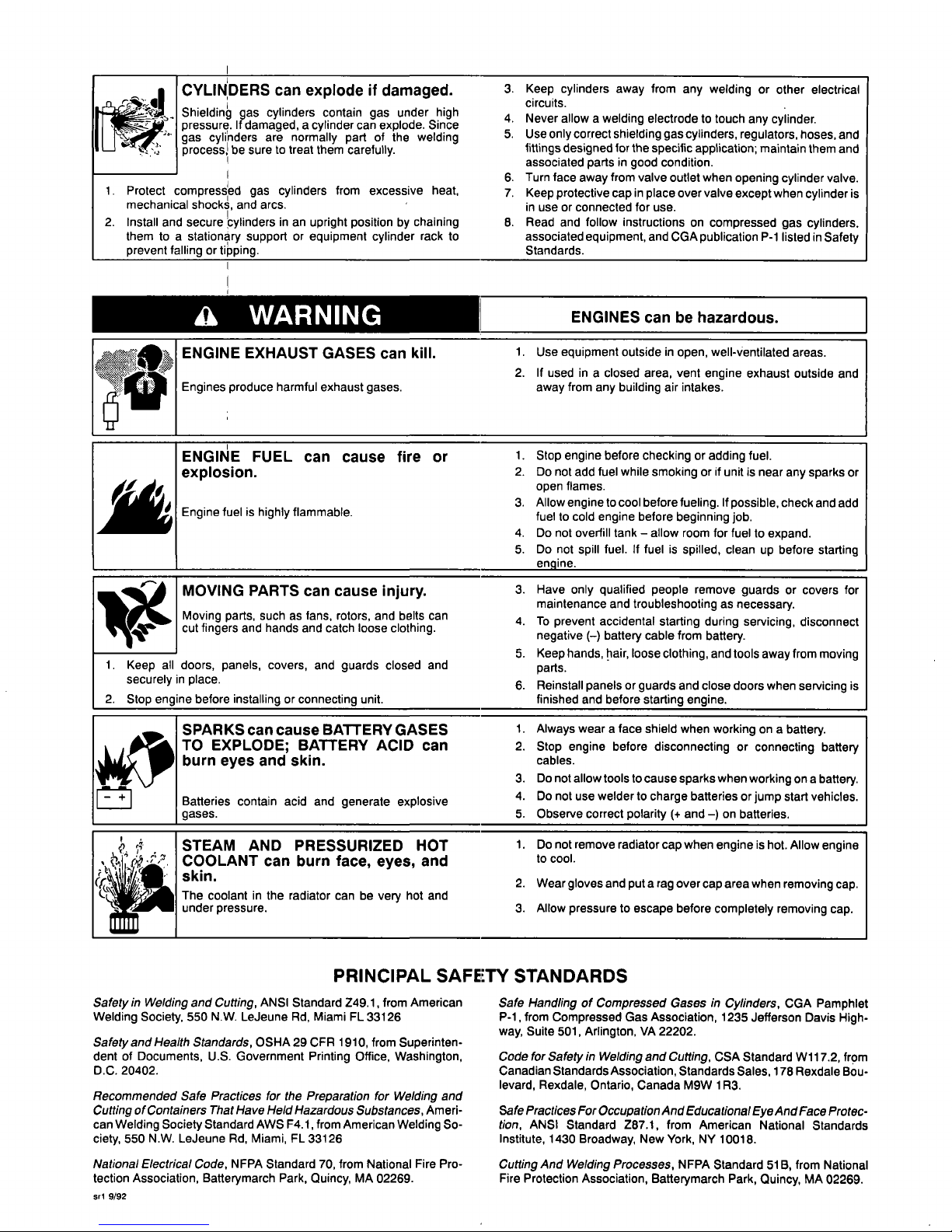
CYLINDERS
can
explodeifdamaged.
Shieldin~
gas
cylinders
contain
gas
under
high
pressure.
If
damaged,
a
cylinder
can
explode.
Since
gas
cylinders
are
normally
part
of
the
welding
process~
be
sure
to
treat
them
carefully,
3.
4.
5.
Keep
cylinders
away
from
any
welding
or
other
electrical
Never
allow
a
welding
electrode
to
touch
any
cylinder.
circuits.
Use
only
correct
shielding
gas
cylinders,
regulators,
hoses,
and
fittings
designed
for
the
specific
application;
maintain
them
and
associated
parts
in
good
condition.
1.
2.
I
Protect
compress~ed
gas
cylinders
from
excessive
heat,
mechanical
shocks,
and
arcs.
Install
and
secure
~ylinders
in
an
upright
position
by
chaining
them
to
a
stationary
support
or
equipment
cylinder
rack
to
prevent
falling
or
ti~ping.
6.
7.
8.
Turn
face
away
from
valve
outlet
when
opening
cylinder
valve.
Keep
protective
cap
in
place
over
valve
except
when
cylinder
is
in
use
or
connected
for
use.
Read
and
follow
instructions
on
compressed
gas
cylinders,
associated
equipment,
and
CGA
publication
P-i
listed
in
Safety
Standards.
I
ENGINES
can
be
hazardous.
ENGINE
EXHAUST
GASES
can
kill.
Engines
produce
harmful
exhaust
gases.
1.
2.
Use
equipment
outside
in
open,
well-ventilated
areas.
If
used
in
a
closed
area,
vent
engine
exhaust
outside
and
away
from
any
building
air
intakes.
E
FUEL
can
cause
fire
or
1.
2.
Stop
engine
before
checkingoradding
fuel.
Do
not
add
fuel
while
smoking
or
if
unit
is
near
any
sparks
or
open
flames.
Engine
fuel
is
highly
flammable.
3.
4.
5.
Allow
engine
to
cool
before
fueling.
If
possible,
check
and add
fuel
to
cold
engine
before
beginning
job.
Do
not
overfill
tankallow
room
for
fuel
to
expand.
Do
not
spill
fuel.Iffuel
is
spilled,
clean
up
before
starting
engine.
MOVING
PARTS
can
cause
injury.
3.
Have
only
qualified
people
remove
guards
or
covers
for
maintenance
and
troubleshooting
as
necessary.
Moving
parts,
such
as
fans,
rotors,
and
belts
can
cut
fingers
and
hands
and
catch
loose
clothing,
4.
To
prevent
accidental
starting
during
servicing,
disconnect
negative
()
battery
cable
from
battery.
I.
Keep
all
doors,
panels,
covers,
and
guards
closed
and
securely
in
place.
5.
6.
Keep
hands,
hair,
loose
clothing,
and
tools
away
from
moving
parts.
Reinstall
panels
or
guards
and
close
doors
when
servicing
is
2.
Stop
engine
before
installing
or
connecting
unit,
finished
and
before
starting
engine.
SPARKS
can
cause
BATTERY
GASES
1.
Always
wear
a
face
shield
when
working
on
a
battery.
TO
EXPLODE;
BATTERY
ACID
can
2.
Stop
engine
before
disconnecting
or
connecting
battery
burn
eyes
and
skin,
cables.
Batteries
contain
acid
and
generate
explosive
iases.
3.
4.
5.
Do
not
allow
tools
to
cause
sparks
when
working
on
a
battery.
Do
not
use
welder
to
charge
batteries
or
jump
start
vehicles.
Observe
correct
polarity
(+
and
)
on
batteries.
r~.
~
.
.~
Y
~
STEAM
AND
COOLANT
can
skin.
The
coolantinthe
r
under
pressure.
PRESSURIZED
burn
face,
eyes,
adiator
can
be
very
h
HOT
and
ot
and
1.
2.
3.
Donotremoveradiatorcapwhenengineishot.Allowengine
to
cool.
Wear
gloves
and
put
a
rag
over
cap
area
when
removing
cap.
Allow
pressuretoescape
before
completely
removing
cap.

PRECAUTIONS
DE
SECURITE
EN
SOUDAGE
A
LARC
MISE
EN
GARDE
LE
SOUDAGE
A
LARC
est
dangereux.
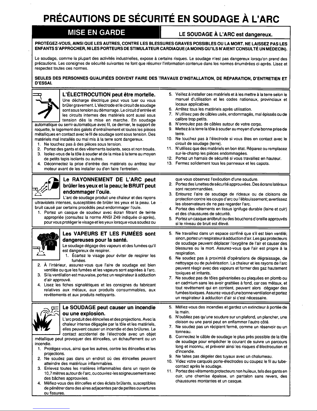
PROTEGEZ-VOUS,
AINSI
QUE
LES
AUTRES,
CONTRE
LES
BLESSURES
GRAVES
POSSIBLES
OU
LA
MORT.
NE
LAISSEZ
PAS
LES
ENFANTS
SAPPROCHER,
NI
LES
PORTEURS
DE
STIMULATEUR
CARDIAQUE
(A
MOINS
QUILS
NAIENT
CONSULTE
UN
MEDECIN).
DESSAI.
LELECTROCUTION
peut
Œtre
mortelle.
~
Une
dØcharge
Olectrique
peut
vous
tuer
ou
vous
brUler
gravement.
LØlectrodeetle
circuit
de
soudage
sont
sous
tension
au
dØmarrage.
Le
circuit
dentrØe
et
les
circuits
internes
des
matØriels
sont
aussi
sous
__________
tension
des
Ia
mise
en
marche.
En
soudage
automatique
ou
semi-automatique
avec
f
ii,cedernier,
le
support
de
roquette,
le
logement
des
galets
dentrainement
et
toutes
les
piŁces
metalliques
en
contact
avec
le
f
ii
de
soudage
sont
sous
tension.
Des
matŁriels
mal
installØs
ou
mal
misaIa
terre
sont
dangereux.
1.
Ne
touchez
pas
a
des
piŁces
sous
tension.
2.
Portez
des
gants
et
des
vØtements
isolants,
secsetnon
trouØs.
3.
lsolez-vousdeIa
tleasouderetdeIamise
ala
terre
au
moyen
de
petits
tapis
isolants
ou
autres.
4.
DØconnectez
Ia
prise
dentrØe
des
matOrielsouarrŒtez
leur
moteur
avant
de
les
installerouden
faire
lentretien.
~
Le
RAYONNEMENT
DE
LARC
peut
brUler
Ies
yeux
et
Ia
peau;
le
BRUIT
peut
endommager
IouIe.
Larc de
soudage
produit
une
chaleuretdes
rayons
ultraviolets
intenses,
susceptibles
de
brUler
les
yeux
et
Ia
peau.
Le
bruit
cause
par
certains
procØdØs
peut
endommager
louIe.
1.
Portez
un
casque
de
soudeur
avec
Łcran
filtrant
de
teinte
appropriee
(consultez
Ia
norme
ANSI
Z49
indiquee
ci-aprŁs),
pour
vous
protØgerlevisage
et
les
yeux
lorsque
vous
soudez
ou
5.
Veillez
a
installer
ces
matØriels
eta
les
mettre
a
Ia
terre
selon
le
manuel
dutilisationetles
codes
nationaux,
provinciaux
et
locaux
applicables.
6.
ArrØtez
tous
es
matŁriels
aprŁs
utilisation.
7.
Nutilisez
pas
de
cables
uses,
endommages,
mal
Opisses
ou
de
calibre
trop
petits.
8.
Nenroulez
pas
de
cables
autourdevotre
corps.
9.
Mettez
ala
terre
Ia
tle
a
souder
au
moyen
dune
bonne
prise
de
terre.
10.
Ne
touchez
pas
a
lØlectrode
si
vous
Øtes
en
contact
avec
le
circuit
de
soudage
(terre).
11.
Nutilisez
que
des
matØriels
en
bon
Øtat.
RŁparez
ou
remplacez
sur-le-champ
les
piŁces
endommagees.
12.
PortezunharnaisdesØcuritØ
si
vous
travaillez
en
hauteur.
13.
Fermez
solidement
touS
les
panneaux
et
les
capots.
que
vous
observez
lexØcution
dune
soudure.
2.
Portez
des
lunettes
de
sŁcuritØ
approuvØes.
Des
Łcrans
latØraux
sont
recommandØes.
3.
Entourez
laire
de
soudage
de
rideaux
ou
de
cloisons
de
protection
contre
les
coups
darc
ou
lØblouissement;
avertissez
les
observateurs
de
ne
pas
regarder
arc.
4.
Portez
des
vØtements
en
tissus
ignifuge
durable
(lame
et
cuir)
et
des
chaussures
de
sØcuritØ.
5.
Portez
un
casque
antibruitoudes
bouchons
doreille
approuvŁs
sileniveau
de
bruit
est
ØlevŁ.
Les
VAPEURS
ET
LES
FUMEES
sont
dangereuses
pour
Ia
sante.
Le
soudage
dŁgage
des
vapeurs
et
des
fumŁes
quil
~
.
est
dangereuxderespirer.
1.
Ecartez
le
visage
pour
Łviter
de
respirer
les
fumŁes.
2.
A
lintØrieur,
assurez-vous
que
laire
de
soudage
est
bien
ventilØe
ou
que
les
fumŁesetles
vapeurs
sont
aspirØes
a
larc.
3.
SiIaventilation
est
mauvaise,
portez
un
respirateur
a
adduction
dair
approuvØ.
4.
Lisez
es
fiches
signalØtiques
et
es
consignes
du
fabricant
relatives
aux
mØtaux,
aux
produits
consummables,
aux
revŒtements
et
aux
produits
nettoyants.
Le
SOUDAGE
peut
causer
un
incendie
ou
une
explosion.
Larc
produit
des
Øtincelles
et
des
projections.
Avec
Ia
chaleur
intense
degagee
par
a
tleetles
matØriels,
elles
peuvent
causer
un
incendieetdes
brlures.
Le
contact
accidenteldelelectrode
avec
un
objet
mŁtallique
peut
provoquer
des
Øtincelles,
un
Łchauffement
ou un
incendie.
1.
Protegez-vous,
ainsi
que
les
autres,
contre
les
Łtincellesetles
projections.
2.
Ne
soudez
pas
dansunendroitodes
Øtincelles
peuvent
atteindre
des
matŁriELux
inflammables.
3.
Enlevez
toutes
les
rnatiŁres
inflammables
dans
un
rayon
de
10,7
metres
autourdE
larc,
ou
couvrez-Ies
soigneusement
avec
des
bches
approuvØes.
4.
MØfiez-vous
des
Øtincelles
et
des
Øclats
brlants,
susceptibles
de
pØnØtrer
dans
des
aires
adjacentes
par
de
petites
ouvertures
ou
fissures.
5.Netravaillez
dans
un
espace
confine
que
sil
est
bien
ventilØ;
sinon,
portez
un
respirateuraadduction
dair.
Lesgaz
protecteurs
de
soudage
peuvent
dØplacer
IoxygŁne
de
lair
et
causer
des
blessuresouIa
mort.
Assurez-vous
que
lair
est
propre
a
Ia
respiration.
6.
Ne
soudez
pas
a
proximitØ
dopŁrations
de
dŁgraissage,
de
nettoyage
ou
de
pulvØrisation.
La
chaleur
et
les
rayons
de
larc
peuvent
rØagir
avec
des
vapeurs
et
former
des
gaz
hautement
toxiques
et
irritants.
7.Nesoudez
pas
de
tles
galvanisees
ou
plaquŁes
en
p10mb
ou
en
cadmium
sans
les
avoir
grattØes
a
fond,
car
ces
mØtaux,
et
tout
revŒtement
qui
en
contient,
peuvent
alors
dŁgager
des
fumeestoxiques.
Assurez-vousdune
bonneventilation
etportez
un
respirateur
a
adduction
dair
si
cest
nØcessaire.
5.
MŁfiez-vous
des
incendies
et
gardez
un
extincteur
a
poilØe
de
Ia
main.
6.
Noubliez
pas
quune
soudure
sur
un
plafond,unplancher,
une
cloison
ou
une
paroi
peut
en
enflammer
lautre
ctØ.
7.
Ne
soudez
pas
un
recipient
termŁ,
comme
un
reservoir
ou
un
tonneau.
8.
Connectez
le
cable
de
soudageleplus
prŁs
possible
de
Ia
tIe
de
soudage
pour
empŒcher
le
courant
de
suivre
un
parcours
long
et
inconnu,
et
prØvenir
ainsi
les
risques
dØlectrocution
et
dincendie.
9.Nefaites
pas
degeler
des
tuyaux
avec
un
chalumeau.
10.
Videz
votre
carquois
porte-electrodes
ou
coupez
le
fil
au
tube
contact
aprŁs
le
soudage.
11.
Portez
des
vŁtements
protecteurs
non
huileux,
tels
des
gants
en
cuir,
une
chemise
epaisse,
un
pantalon
sans
revers,
des
chaussures
montarites
et
un
casque.
Le
soudage,
comme
Ia
plupart
des
activitØs
industrielles,
expose
a
certains
risques.
Le
soudage
nest
pas
dangereux
lorsquon
prend
des
precautions.
Les
consignes
de
sØcuritØ
suivantesnefont
que
rØsumer
information
contenue
dans
les
normes
ØnumØrØes
ci-aprŁs.
Lisez
et
respectez
toutes
ces
normes.
SEULES
DES
PERSONNES
QUALIFIEES
DOIVENT
FAIRE
DES
IRAVAUX
DINSTALLATION,
DE
REPARATION,
DENTRETIEN
ET
I

Les
BOUTEILLES
endommagees
peuvent
exploser.
Les
bouteilles
contiennent
des
gaz
protecteurs
sous
haute
pression.
Des
bouteilles
endommagees
peuvent
exploser.
C;omme
les
bouteilles
font
normalement
partie
du
procedØ
de
soudage,
traitez-les
avec
soin.
1.
Les
bouteilles
doivent
Œtre
protegees
contre
les
sources
de
chaleur
intense,
es
chocsetles
arcs
de
soudage.
2.
Enchainez
verticalementesbouteilles
a
un
support
ouaun
cadre
fixe
pour
les
empŒcher
de
tomberoudŒtre
renversØes.
3.
Eloignez
les
bouteilles
de
tout
circuit
electrique
ou
de
soudage.
MIS~
EN
GARDE
Le
CARBURANT
peut
causer
un
incendie
ou
une
explosion.
Le
carburarit
est
hautement
inflammable.
1.
ArrŒte:~
le
moteur
avant
de
verifier
le
niveau
de
carburantoude
faire
le
plein.
2.Nefaites
pas
le
plein
en
fumant
ou
proche
dune
source
Des
PI¨CES
EN
MOUVEMENT
peuvent
causer
des
blessures.
Des
piŁces
en
mouvement,
telles
des
ventilateurs,
des
rotors
et
des
courroies
peuvent
couper
les
doigts
et
les
mains,
ou
accrocher
des
vŒtements
amples.
1.
Assurez-vous
que
les
portes,
les
panneaux,
les
capots
et
les
protecteurs
sont
bien
lermØs.
2.
Avant
dinstaller
ou
de
connecter
un
systŁme,
arrŒtez-en
le
moteur.
3.
Seules
des
personries
qualifiees
doivent
dØmonter
des
4.
EmpŒchez
tout
contact
entre
une
bouteille
et
une
electrode.
5.
Nutilisez
que
des
bouteilles
de
gaz
protecteur,
des
dØtendeurs,
des
flexibles
et
des
raccords
conus
pour
chaque
application
specifique;
ces
matØriels
et
les
piŁces
connexes
doivent
Œtre
en
bon
Øtat.
6.
Ne
mettez
pas
le
visage
devant
le
robinet
de
bouteille
en
louvrant.
7.
Remettez
le
chapeau
de
bouteille
aprŁs
utilisation.
8.
Lisez
et
respectez
les
consignes
relatives
aux
bouteilles
de
gaz
comprime
et
aux
matØriels
connexes,
ainsi
que
Ia
publication
P-i
de
Ia
CGA,
ØnumØrŁes
dans
les
normes
ci-dessous.
Les
MOTEURS
peuvent
Œtre
dangereux.
1.
Utilisez
des
machines
a
lextØrieur
dans
des
aires
ouvertes
et
bien
ventilØes.
2.
Si
vous
utilisez
des
machines
dansunendroit
confine,
les
fumØes
dØchappement
doivent
Œtre
envoyees
a
lextØrieur,
loin
des
prises
dair
du
btiment.
dØtincelles
ou
dune
flamme
nue.
3.
Si
cest
possible,
laissez
le
moteur
refroidir
avant
de
faire
le
plein
de
carburantouden
verifier
le
niveauaudebut
du
soudage.
4.
Ne
faites
pas
le
plein
de
carburant
a
ras
bord
:
prØvoyez
de
lespace
pour
son
expansion.
5.
Faites
attention
de
ne
pas
renverser
de
carburant.
Nettoyez
tout
carburant
renversØ
avant
de
faire
dØmarrer
le
moteur.
protecteurs
ou
des
capots
pour
faire
lentretienoule
depannage
nØcessaire.
4.
Pour
empŒcher
un
demarrage
accidentel
dun
systŁme
pendant
lentretien,
dØbranchez
le
cable
daccumulateur
a
Ia
borne
negative.
5.
Napprochez
pas
les
mains
ou
es
cheveux
de
piŁces
en
mouvement;
elles
peuvent
aussi
accrocher
des
vŒtements
amples
et
des
outils.
6.
RØinstallez
les
capots
ou
les
protecteurs
et
fermez
les
portes
aprŁs
des
travaux
dentretien
et
avant
de
faire
dŁmarrer
le
moteur.
Le
liquide
do
refroidissement
dun
radiateur
peut
Œtre
brlant
et
sous
pression.
PRINCIPALES
NORMES
DE
SECURITE
Safety
in
Welding
and
Cutting
norme
ANSI
Z49.1,American
Welding
Society,
550,
N.W.
LeJeun~
Rd.,
MiamiFL33128.
Safety
and
Health
Standarc~
OSHA
29
CFR
1910,
Superintendent
of
Documents,
U.S.
Government
Printing
Office,
Washington
D.C.
20402.
Recommended
Safe
Practices
For
the
Preparation
For
Welding
and
GuthnQof
Containers
That
F~ave
Held
Hazardous
Substances,
norme
AWS
F4.i,
American
Welding
Society,
550,
N.W.
LeJeune
Rd.,
Miami
FL
33128.
Safe
Handling
of
Com~ressed
Gases
in
Cylinders
document
P-i,
Compressed
Gas
Association,
1235
Jefferson
Davis
Highway,
Suite
501,
Arlington,
Va
22202.
Code
for
Safety
in
Welding
and
Cutting
norme
CSA
Wi
17.2,
Asso
ciation
canadienne
de
normalisation,
Standards
Sales,
176
Rexdale
Boulevard,
Rexdale,
Ontario,
Canada
M9W1R3.
Safe
Practices
for
Occupation
and
Educational
Eve
and
Face
Protec
ILQI:1,
norme
ANSI
Z87.i
,American
National
Standards
Institute,
1430
Broadway,
New
York,
NY
10018.
National
Electrical
Code
norme
70
NFPA,
National
Fire
Protection
Association,
Batterymarch
Park,
Quincy,
MA
02269.
srlf
9/91
Cutting
and
Welding
PrOcesses
norme
SiB
NFPA,
National
Fire
Protection
Association,
Batterymarch
Park,
Quincy,
MA
02269.
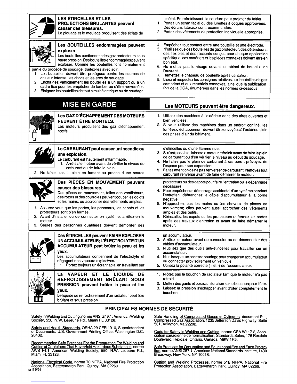
LES
ETINCELLES
ET
LES
metal.
En
refroidissant,
Ia
soudure
peut
projeter
du
laitier.
PROJECTIONS
BRULANTES
peuvent
causer
des
blessures.
Le
piquage
et
le
meulage
produisent
des
Øclats
de
1.
2.
PortezunØcran
facialoudes
lunettes
a
coques
approuvØes.
Des
Øcrans
latØraux
sont
recommandØs.
Portez
des
vŒtements
de
protection
individuelle
appropriØs.
Les
GAZ
DECHAPPEMENT
DES
MOTEURS
PEUVENT
ETRE
MORTELS.
Les
moteurs
produisent
des
gaz
dechappement
nocifs.
Des
ETINCELLES
peuvent
FAIRE
EXPLOSER
un
accumulateur.
UNACCUMULATEUR;LELECTROLYTEDUN
2.
ArrŒtez
le
moteur
avantdeconnecter
ou
de
dØconnecter
des
cables
daccumulateur.
ACCUMUI.ATEUR
peut
brUler
Ia
peau
et
les
~
Nutilisez
que
des
outils
anti-Øtincelles
pour
travailler
sur
un
yeux.
accumulateur.
Les
accumjlateurs
contiennent
de
lelectrolyte
et
4.
Nutilisezpasunpostedesoudagepourchargerunaccumulateur
degagent
d~s
vapeurs
explosives.
ou
connecter
provisoirement
un
vØhicule.
1.
Portez
toujours
un
Øcran
facialentravaillant
sur
5.
Utilisez
Ia
polaritØ
correcte
(+
et
-)
de
laccumulateur.
La
VAPEU
R
ET
LE
LIQUI
DE DE
1.
Ntez
pas
le
bouchon
de
radiateur
tant
que
le
moteur
na
pas
REFROIDISSEMENT
BRULANT
SOUS
refroidi.
PRESSIONI
peuvent
brUler
Ia
peau
et
les
2.
Mettez
des
gants
et
posez
un
torchon
sur
le
bouchon
pour
lter.
e
3.
Laissez
Ia
pression
sechapper
avant
dter
completement
le
~
U
.
bouchon.

EMF
INFORMATION
TABLE
OF
CONTENTS
SECTION
1
-
SAFETY
INFORMATION
SECTION
2
SPECIFICATIONS
2-1.
Volt-Ampere
Curves
2-2.
Duty
Cycle
SECTION
3
INSTALLATION
3-1.
Selecting
A
Location
And
Moving
Welding
Power
Source
3-2.
Selecting
And
Preparing
Weld
Output
Cables
3-3.
Connecting
To
Weld
Output
Terminals
3-4.
Remote
14
Receptacle
Information
And
Connections
3-5.
Connecting
Input
Power
SECTION
4-
OPERATION
9
SECTION
6-
ELECTRICAL
DIAGRAMS
17
SECTION
7
TUNGSTEN
ELECTRODE
7-1.
Selecting
Tungsten
Electrode
7-2.
Preparing
Tungsten
SECTION
8
PARTS
LIST
Figure
8-1.
Main
Assembly
Figure
8-2.
Panel,
Rear
w/Components
Figure
8-3.
Terminal
Assembly,
Pri
Figure
8-4.
Swil:ch,
PB
Figure
8-5.
Rectifier,
SCR
NOTE
~
Considerations
About
Welding
And
The
Effects
Of
Low
Frequency
Electric
And
-~
Magnetic
Fields
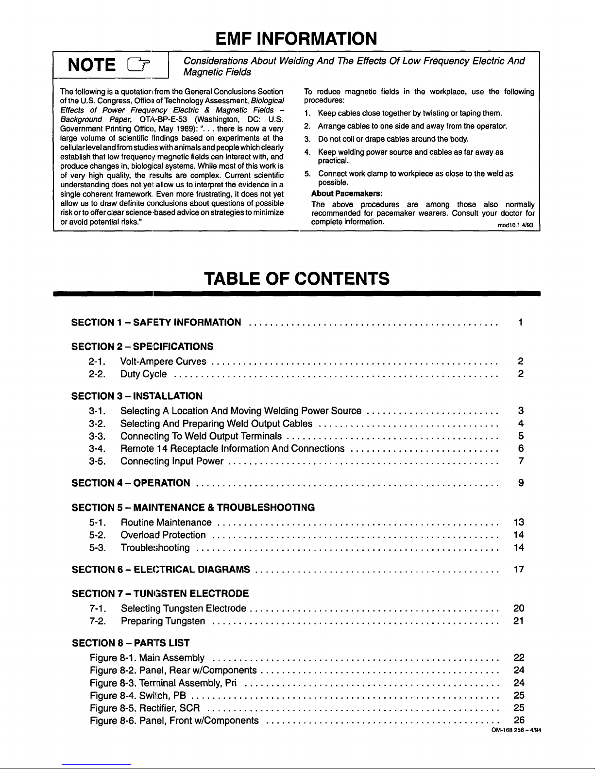
The
following
is
a
quotation
from
the
General
Conclusions
Section
of
the
U.S.
Congress,
Office
of
Technology
Assessment,
Biological
Effects
of
Power
Frequ9ncy
Electric
&
Magnetic
Fields
Background
Paper,
OTA-BP-E-53
(Washington,
DC:
U.S.
Government
Printing
Office,
May
1989):
.
.
.
there
is
now
a
very
large
volumeofscientific
findings
based
on
experiments
at
the
cellular
level
and
from
studies
with
animals
and
people
which
clearly
establish
that
low
frequency
magnetic
fields
can
interact
with,
and
produce
changes
in,
biological
systems.
While
most
of
this
work
is
of
very
high
quality,
the
results
are
complex.
Current
scientific
understanding
does
not
yet
allow
us
to
interpret
the
evidence
in
a
single
coherent
framework,
Even
more
frustrating,
it
does
not
yet
allow
us
to
draw
definite
conclusions
about
questionsofpossible
risk
or
to
offer
clear
science
~based
advice
on
strategies
to
minimize
or
avoid
potential
risks.
To
reduce
magnetic
fieldsinthe
workplace,
use
the
following
procedures:
1.
Keep
cables
close
together
by
twistingortaping
them.
2.
Arrange
cables
to
one
side
and
away
from
the
operator.
3.
Do
not
coil
or
drape
cables
around
the
body.
4.
Keep
welding
power
source
and
cables
as
far
away
as
practical.
5.
Connect
work
clamp
to
workpiece
as
close
to
the
weld
as
possible.
About
Pacemakers:
The
above
procedures
are
among
those
also
normally
recommended
for
pacemaker
wearers.
Consult
your
doctor
for
complete
information.
modlO
1
4/93
2
2
3
4
5
6
7
SECTION
5
MAINTENANCE
&
TROUBLESHOOTING
5-1.
Routine
Maintenance
5-2.
Overlo&J
Protection
5-3.
Troubleshooting
13
14
14
20
21
22
24
24
25
25
Figure
8-6.
Panel,
Front
w/Components
26
OM.168
256
4/94


SECTION
1
-
SAFE~TY
INFORMATION
Read
all
safety
messages
throughout
this
manual.
Obey
all
safety
messages
to
avoid
injury.
Learn
thi?
meaning
of
WARNING
and
CAUTION.
modl.1
2/93
iIIi1~I
Figure
1-1.
Safety
Information
SECTION
2
SPECIFICATIONS
Table
2-1.
Welding
Power
Source
1
2
!
:
2
ELECTRIC
SHOCK
can
kIII.~
Do
not
touch
live
electrical
parts.
~fl
Disconnect
input
power
before
-~_________
installingorservicing.
CA~
/
5
~
w~OVING
PARTS
can
Injure.
)~
S
Keep
away
from
moving
parts.
S
Keep
all
panels
and
covers
closed
wtten
operating.
1
Safety
Alert
Symbol
2
Signal
Word
WARNING
means
possible
death
or
serious
injury
can
happen.
CAUTION
means
possible
minor
injury
or
equipment
damage
can
happen.
3
StatementOfHazard
And
Result
6
a
WARNIF~
7-H
NOTE
D~
READ
SAFETY
BLOCKS
at
start
of
I
_____
SectIon
3-1
berore
proceeding.
Turn
Off
switch
when
using
high
frequency.
4
Safety
InstructionsToAvoid
Hazard
5
Hazard
Symbol
(If
Available)
6
Safety
Banner
Read
safety
blocks
for
each
sym
bol
shown.
7
NOTE
Special
instructions
for
best
oper
ation
not
related
to
safety.
Specifications
Description
Type
Of
Output
Welding
Process
Max
Open-Circuit
Voltage
TypeOfInput
Power
Overall
Dimensions
Input
Amperes
At
Rated
Output
Constant
Current/Direct
Currerlt
(CC/DC)
Shielded
Metal
Arc
(SMAW)
And
Gas
Tungsten
Arc
(GTAW)
Welding
70
Volts
DC
Three-Phase;
220,
380,
400,
Or
415
Volts
AC,
50/60
Hz
See
Figure
3-2
102
A
At
220
V,
59
AAt380
V,
56
A
At
400
V,
54
AAt415
V
510
Amperes,
41
VoltsDCAt
~I5%
Duty
Cycle
(see
Section
2-2)
38.8
kVN25.6
kW
Low:
20-270
A;
High:
37-510
A
Net:
543
lb
(246
kg);
Ship:
568
lb
(258
kg)
Rated
Weld
Output
KVAJKW
UsedAtRated
Output
Amperage Range
Weight
OM-168
256
Page
1

2-1.
Volt-Ampere
Curves
Figure
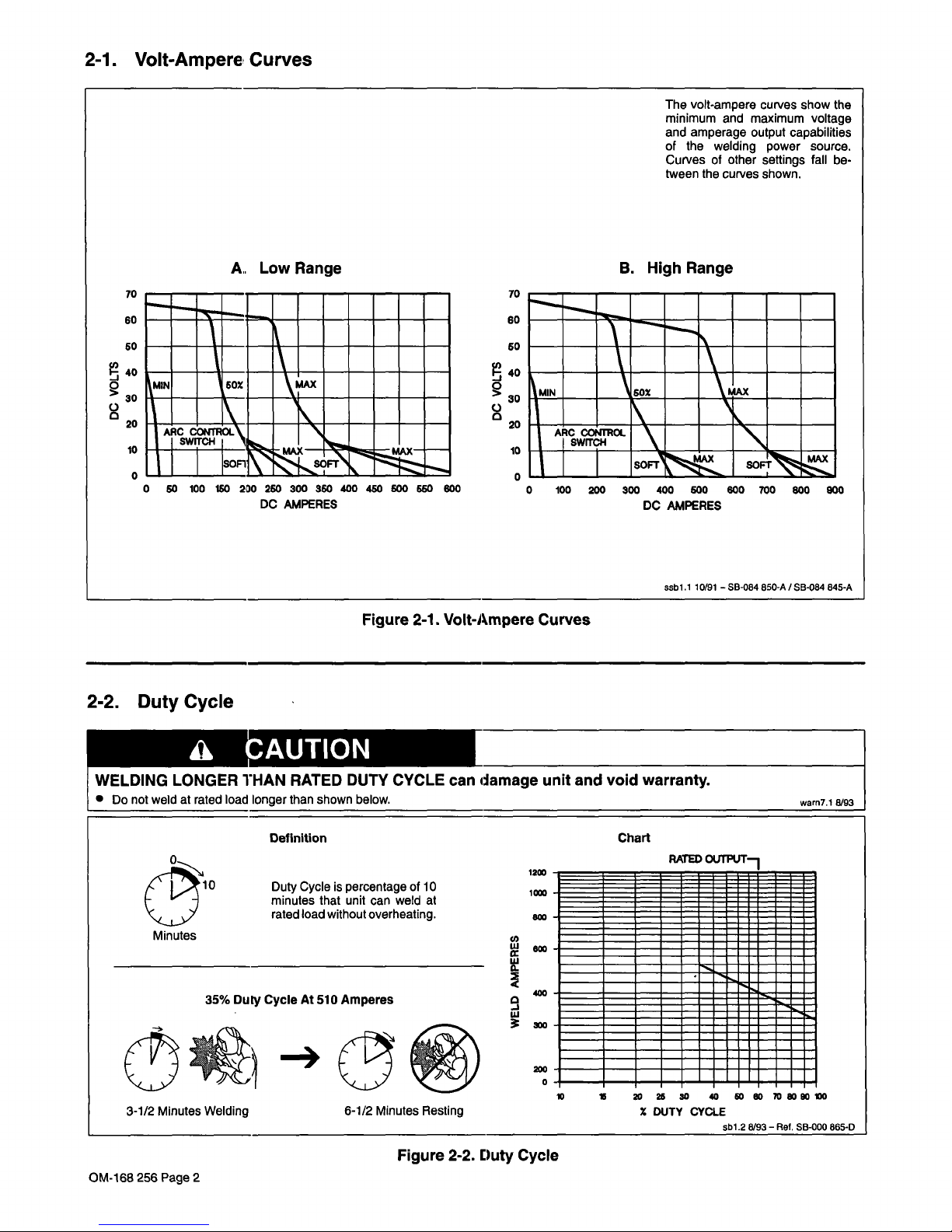
2-1.
Volt-Ampere
Curves
2-2.
Duty
Cycle
L
~AUTION
WELDING
LONGER
THAN
RATED
DUTY
CYCLE
can
damage
unit
and
void
warranty.
Do
not
weldatrated
load
longer
than
shown
below.
warn7.1
8/93
A~.
Low
Range
The
volt-ampere
curves
show
the
minimum
and
maximum
voltage
and
amperage
output
capabilities
of
the
welding
power
source.
Curvesofother
settings
fall
be
tween
the
curves
shown.
B.
High
Range
70
60
50
40
0
>
30
C.)
20
10
0
70
60
50
40
0
>
30
C.)
20
10
0
0
50
100
150
2D0
250
300
350
400
450
500
650
600
DC
AMPERES
0
100
200
300
400
600
600
700
800
900
DC
AMPERES
ssbl
.110/91SB-084
850-A/SB-084
845-A
Definition
Chart
1200
Duty
Cycle
is
percentage
of
10
minutes
that
unit
can
weld
at
rated
load
without
overheating.
(1)
~O00
35%
Duly
Cycle
At
510
Amperes
ii~
~
3-1/2
Minutes
Welding
6-1/2
Minutes
Resting
Z
DUTY
CYCLE
sbl
.2
8/93Aol.
SB-000
865-D
Figure
2-2.
Duty
Cycle
OM-168
256
Page
2

SECTION
3-
INSTALLATION
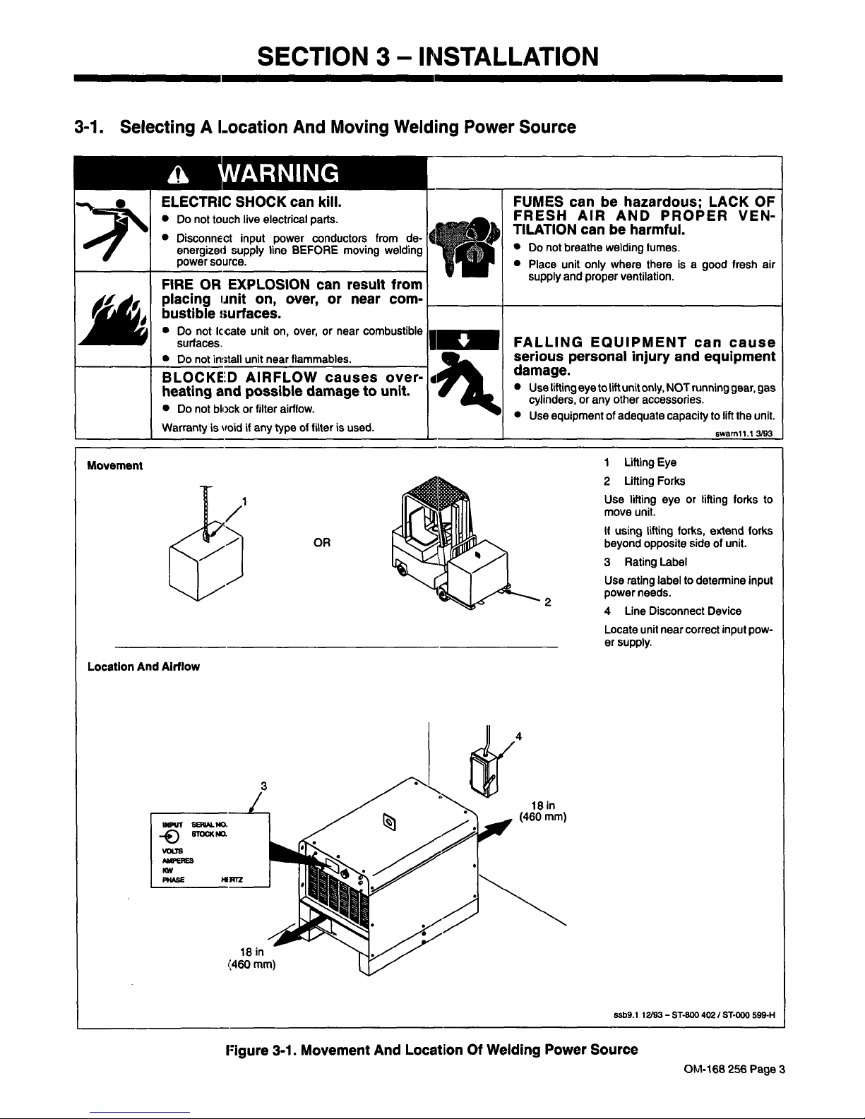
3-1.
Selecting
A
Location
And
Moving
Welding
Power
Source
£~
~NARNING
ELECTRIC
SHOCK
can
kill.
Do
not
touch
live
electrical
parts.
Disconnect
input
power
conductors from
de
energized
supply
line
BEFORE
moving
welding
power
source.
FIRE
OR
EXPLOSION
can
result
from
placing
unit
on,
over,
or
near
com
bustible
t~urfaces.
Do
not
iccate
unit
on,
over,
or
near
combustible
surfaces.
Do
not
install
unit
near
flammables.
BLOCKED
AIRFLOW
causes
over
heating
and
possible
damage
to
unit.
Do
not
block
or
filter
airflow.
Warranty
is
~oid
if
any
type
of
filter
is
used.
I
FALLING
EQUIPMENT
can
cause
serious
personal
Injury
and
equipment
damage.
Use
lifting
eye
to
lift
unit
only,
NOT
running
gear,
gas
cylinders,
or
any
other
accessories.
Use
equipmentofadequate
capacity
to
lift
the
unit.
cwarnhil
3/93
Figure
3-1.
Movement
And
Location
Of
Welding
Power
Source
FUMES
can
be
hazardous;
LACK
OF
FRESH
AIR
AND
PROP
ER
VEN
TILATION
can
be
harmful.
Do
not
breathe
welding
fumes.
Place
unit
only
where
there
is
a
supply
and
proper
ventilation.
good
fresh
air
Movement
OR
Location
And
Airflow
1
Lifting
Eye
2
Lifting
Forks
Use
lifting
eye
or
lifting
forks
to
move
unit.
If
using
lifting
forks,
extend
forks
beyond
opposite
sideofunit.
3
Rating
Label
Use
rating
labeltodetermine
input
power
needs.
4
Line
Disconnect
Device
Locate
unit
near
correct
input
pow
er
supply.
ssb9.1
12193-
ST-BOO
402
I
ST-000
599-H
4
l8in
(460
mm)
18
in
~460
mm)
OM-168
256
Page
3

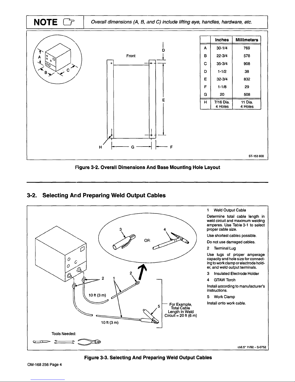
NOTE
LI~ii~
Overall
dimensions
(A,
B,
and
C)
include
lifting
eye,
handles,
hardware,
etc.
I
D
Inches
Millimeters
A
30-1/4
769
Front
B
22-3/4
578
D
1-1/2
38
E
32-3/4
832
~-
C
35-3/4
908
F
1-1/8
29
G
20
508
E
H
7/l6Dia.
11
D~a.
/
4
Holes
4
Holes
1~
H
G
F
ST-153
600
:igure
3-2.
Overal
Dimensions
And
Base
Mounting
Hole
Layout
3-2.
Selecting
Arid
Preparing
Weld
Output
Cables
1
Weld
Output
Cable
Determine
total
cable
length
in
weld
circuit
and
maximum
welding
amperes.
Use
Table
3-1toselect
proper
cable
size.
Use
shortest
cables
possible.
Do
not
use
damaged
cables.
~
2
Terminal
Lug
Use
lugs
of
proper
amperage
capacity
and
hole
size
for
connect
ing
to
work
clamp
or
electrode
hold
er,
and
weld
output
terminals.
3
Insulated
Electrode
Holder
4
GTAW
Torch
Install
according
to
manufacturers
instructions.
5
Work
Clamp
For
Example,
Install
onto
work
cable.
Total
Cable
Length
In
Weld
Circuit=20
ft
(6
m)
Tools
Needed:
c,~
th6.5
11/92
S~0752
10
ft
(3m)
Figure
3-3.
Selecting
And
Preparing
Weld
Output
Cables
OM-168
256
Page
4

-
-~-,
-
-
p
-
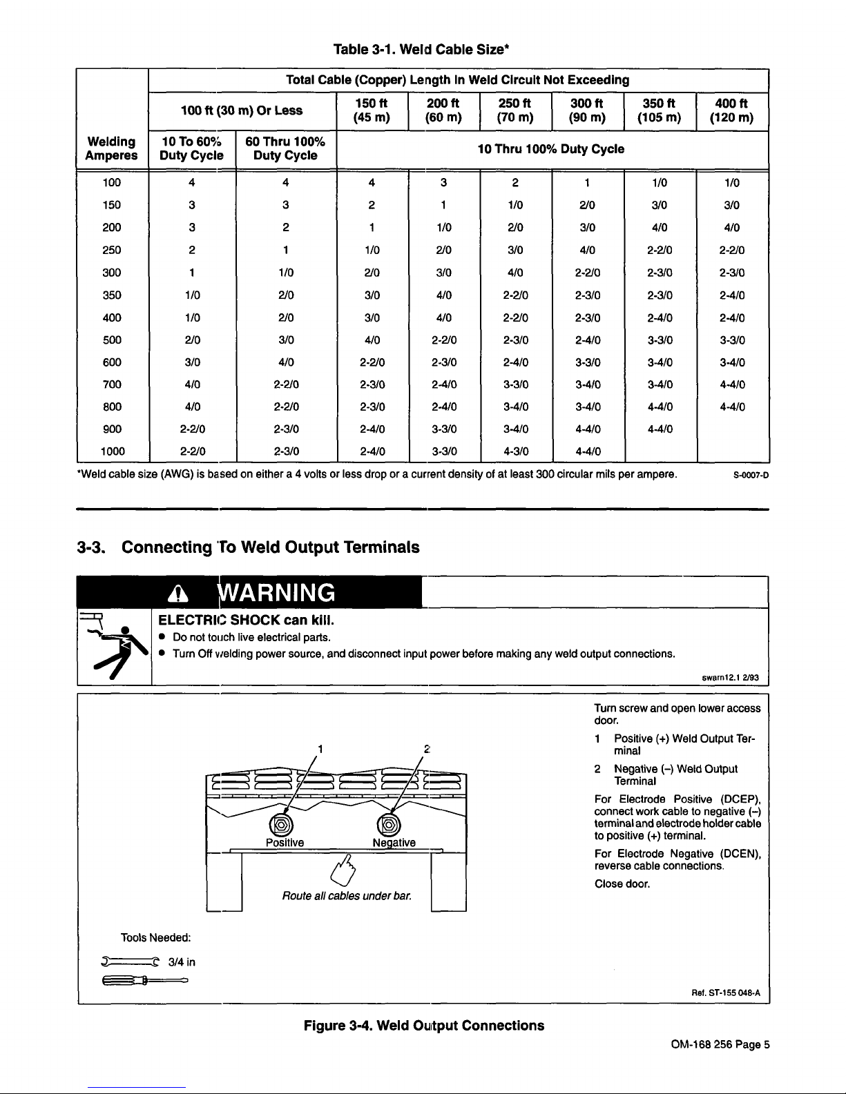
Table
3-1.
Weld
Cable
Size*
4A
~JVARNING
Tools
Needed:
3/4in
~==~
Figure
3-4.
Weld
Oiitput
Connections
Welding
Amperes
Total
Cable
(Copper)
Length
In
Weld
Circuit
Not
Exceeding
100
ft
(30
m)
Or
Less
150ff
I
200ft
I
250ff
I
300ff
I
350ff
I
(45
m)
(60
m)
(70
m)
(90
m)
(105_m)_j~120_m)
400ft
10
To
60%
Duty
Cycle
60
Thru
100%
Duty
Cycle
10
Thru
100%
Duty
Cycle
100
150
200
250
300
350
400
500
600
700
800
900
1000
4
3
3
2
1
1/0
1/0
2/0
3/0
4/0
4/0
2-2/0
2-2/0
4
3
2
1
1/0
2/0
2/0
3/0
4/0
2-2/0
2-2/0
2-3/0
2-3/0
4
2
1
1/0
2/0
3/0
3/0
4/0
2-2/0
2-3/0
2-3/0
2-4/0
2-4/0
3
1
1/0
2/0
3/0
4/0
4/0
2-2/0
2-3/0
2-4/0
2-4/0
3-3/0
3-3/0
2
1/0
2/0
3/0
4/0
2-210
2-2/0
2-3/0
2-4/0
3-3/0
3-4/0
3-4/0
4-3/0
1
210
3/0
4/0
2-2/0
2-3/0
2-3/0
2-4/0
3-3/0
3-4/0
3-4/0
4-4/0
4-4/0
1/0
3/0
4/0
2-2/0
2-3/0
2-3/0
2-4/0
3-3/0
3-4/0
3-4/0
4-4/0
4-4/0
1/0
3/0
4/0
2-2/0
2-3/0
2-4/0
2-4/0
3-3/0
3-4/0
4-4/0
4-4/0
*Weldcable
size
(AWG)
isbased
on
either
a
4
voltsorless
drop
or
a
current
density
ofatleast
300
circular
mils
per
ampere.
5-0007-c
3-3.
Connecting
To
Weld
Output
Terminals
E
LECTRIC
SHOCK
can
kill.
Do
not
touch
live
electrical
parts.
S
Turn
Off
welding
power
source,
and
disconnect
input
power
before
making
any
weld
output
connections.
swarnl2.1
2193
Turn
screw
and
open
lower
access
door.
1
Positive
(+)
Weld
Output
Ter
1
2:
minal
2
Negative
(-)
Weld
Output
For
Electrode
Positive
(DCEP),
connect
work
cable
to
negative
()
terminal
and
electrode
holder
cable
to
positive
(+)
terminal.
For
Electrode
Negative
(DCEN),
reverse
cable
connections.
Close
door.
Rel.
ST-155
048-A
OM-168
256
Page
5

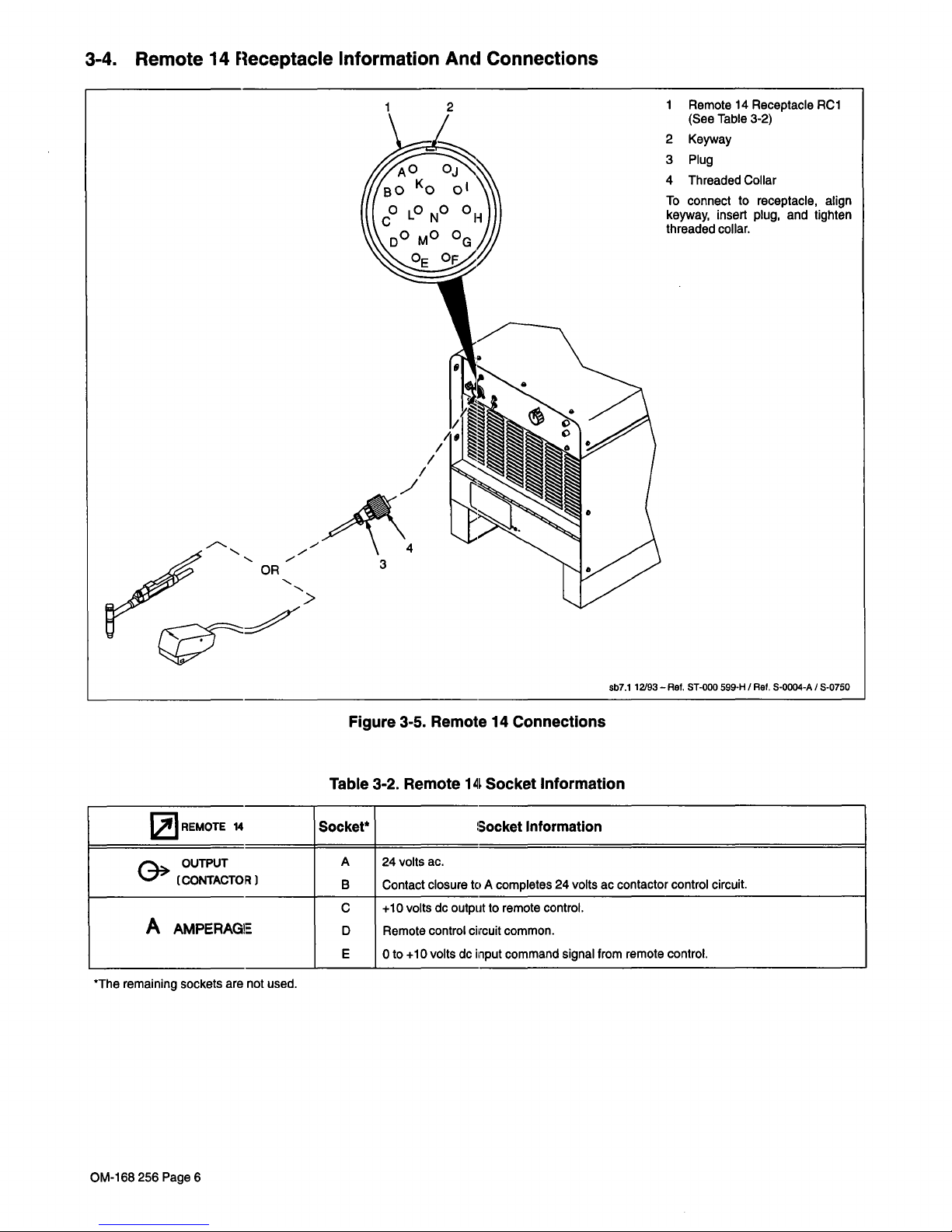
3-4.
Remote
14
Receptacle
Information
And
Connections
Figure
3-5.
Remote
14
Connections
Table
3-2.
Remote
14
Socket
Information
REMOTE
14
Socket*
Socket
Information
OUTPUT
(CONTACTOR)
A
B
24
volts
ac.
Contact
closuretoA
completes
24
volts
ac
contactor
control
circuit.
A
AMPERAGE
C
D
E
+10
volts
dc
output
to
remote
control.
Remote
control
ciircuit
common.
0
to
+10
volts
do
input
command
signal
from
remote
control.
*The
remaining
sockets
are
not
used.
1
Remote
14
Receptacle
Rd
(See
Table
3-2)
2
Keyway
3
Plug
4
Threaded
Collar
To
connect
to
receptacle,
align
keyway,
insert
plug,
and
tighten
threaded
collar.
sbl.1
12193
Ret.
ST-coo
599-H
/
Ret.
5-0004-A
/
5-0750
~
OR
>
3
OM-168
256
Page
6

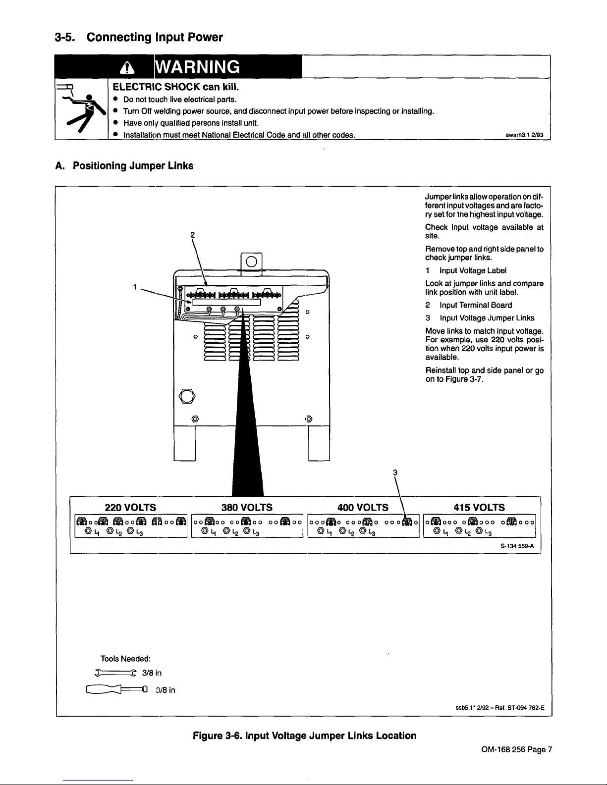
3-5.
Connecting
Input
Power
WARNING
ELECTRIC
SHOCK
can
kill.
Do
not
touch
live
electrical
parts.
Turn
Off
welding
power
source,
and
disconnect
input
power
before
inspectingorinstalling.
Have
only
qualified
persons
install
unit.
Installation
must
meet
National
Electrical
Code
and
all
other
codes
A.
Positioning
Jumper
Links
Remove
top
and
right
side
panel
to
check
jumper
links.
1
Input
Voltage
Label
Look
at
jumper
links
and
compare
link
position
with
unit
label.
2
Input
Terminal
Board
3
Input
Voltage
Jumper
Links
Move
links
to
match
input
voltage.
For
example,
use
220
volts
posi
tion
when
220
volts
input
power
is
available.
Reinstall
top
and
side
panel
or
go
on
to
Figure
3-7.
220
VOLTS
380
VOLTS
400
VOLTS
\
415
VOLTS
~oo~
~oo~
~
oo~Oo
oo~oo
oo~oo~
ooO~O
ooo~o
OOO~~1
o~ooo
o~ooo
O~OOo
~L1
'L2
'L3
~
~L~
'L3
~j
'L~
~
~L3
'L1
'L2
0L3
S-134
559-A
swam3.1
2/93
1
Jumper
links
allow
operation
on
dif
ferent
input
voltages
and
are
facto
ry
set
for
the
highest
input
voltage.
Check
input
voltage
available
at
site.
0
I
Tools
Needed:
~
3/Biii
cIJ===~u
3/8
in
Figure
3-6.
Input
Voltage
Jumper
Links
Location
ssb5.1
2/92
Ref.
5T.094
762-E
OM-168
256
Page
7

 Loading...