

Miller ENPAK Owner's Manual
OM-240 113S
)
2012−10
Description
Mobile Utility Unit With Air Compressor,
Hydraulic Pump, And Auxiliary Power
Capability
)
EnPak
Visit our website at
www.EnPak.com
File: Mobile Utility
From Miller to You
Thank you and congratulations on choosing EnPak® by Miller. Now
you can get the job done and get it done right. We know you don’t have
time to do it any other way.
That’s why when Niels Miller first started building arc welders in 1929,
he made sure his products offered long-lasting value and superior
quality. Like you, his customers couldn’t afford anything less. Miller
products had to be more than the best they could be. They had to be the
best you could buy.
Today, the people that build and sell Miller products continue the
tradition. They’re just as committed to providing equipment and service
that meets the high standards of quality and value established in 1929.
This Owner’s Manual is designed to help you get the most out of your
Miller products. Please take time to read the Safety precautions. They
will help you protect yourself against potential hazards on the worksite.
We’ve made installation and operation quick
and easy. With Miller you can count on years
of reliable service with proper maintenance.
And if for some reason the unit needs repair,
there’s a Troubleshooting section that will
help you figure out what the problem is. The
Miller is the first welding
equipment manufacturer in
the U.S.A. to be registered to
the ISO 9001 Quality System
Standard.
parts list will then help you to decide the
exact part you may need to fix the problem.
Warranty and service information for your
particular model are also provided.
Miller Electric manufactures a full line
of welders and welding related equipment.
For information on other quality Miller
products, contact your local Miller distributor to receive the latest full
line catalog or individual specification sheets. To locate your nearest
distributor or service agency call 1-800-4-A-Miller, or visit us at
www.MillerWelds.com on the web.
EnPak_Thank 2011−09

TABLE OF CONTENTS
SECTION 1 − SAFETY PRECAUTIONS − READ BEFORE USING 1................................
1-1. Symbol Usage 1.......................................................................
1-2. Engine Hazards 1.....................................................................
1-3. Hydraulic Hazards 2...................................................................
1-4. Compressed Air Hazards 3..............................................................
1-5. Additional Symbols For Installation, Operation, And Maintenance 4............................
1-6. California Proposition 65 Warnings 5......................................................
1-7. Principal Safety Standards 5............................................................
SECTION 2 − CONSIGNES DE SÉCURITÉ − LIRE AVANT UTILISATION 6..........................
2-1. Signification des symboles 6............................................................
2-2. Dangers existant en relation avec le moteur 6..............................................
2-3. Dangers liés à l’hydraulique 7............................................................
2-4. Dangers liés à l’air comprimé 8..........................................................
2-5. Dangers supplémentaires en relation avec l’installation, le fonctionnement et la maintenance 9.....
2-6. Proposition californienne 65 Avertissements 10..............................................
2-7. Principales normes de sécurité 10.........................................................
SECTION 3 − DEFINITIONS 12.................................................................
3-1. Symbol Definitions 12...................................................................
SECTION 4 − SPECIFICATIONS 12..............................................................
4-1. Auxiliary Power And Engine Specifications 12...............................................
4-2. Air Compressor Specifications 12.........................................................
4-3. Hydraulic Specifications (Models With Hydraulic Power Source) 12.............................
4-4. Sound Level Table 12...................................................................
4-5. Dimensions, Weights, and Operating Angles 13..............................................
4-6. Fuel Consumption Curves 14.............................................................
4-7. Auxiliary Power Curves 15...............................................................
4-8. Alternator Power Curve 15...............................................................
4-9. Air Compressor Curves 16...............................................................
4-10. Hydraulic Pressure Curves (Models With Hydraulic Power Source) 17..........................
SECTION 5 − PRESTART CHECKS 18...........................................................
5-1. Hydraulic System Prestart Checks (Models With Hydraulic Power Source) 18....................
5-2. Engine Prestart Checks 18...............................................................
5-3. Compressor Prestart Checks 19..........................................................
SECTION 6 − OPERATION 20..................................................................
6-1. Remote Panel (Use With Section 6-2) 20...................................................
6-2. Remote Panel Operation (Use With Section 6-1) 21..........................................
6-3. Safety Interlock 21......................................................................
6-4. Operation And Error Messages 22.........................................................
6-5. Auto Start/Stop Operation 23.............................................................
6-6. Cold Weather Starting And Operation 24...................................................
6-7. Service Panel 26.......................................................................
6-8. Hydraulic Pump Operation (Models With Hydraulic Power Source) 27...........................
SECTION 7 − COMPRESSOR OPERATION 28....................................................
7-1. Air Compressor Controls 28..............................................................
7-2. Compressor Blow Down 29..............................................................
SECTION 8 − MAINTENANCE 30...............................................................
8-1. Maintenance Label 30...................................................................
8-2. Routine Maintenance 31.................................................................
8-3. Servicing Engine Air Cleaner 33...........................................................
8-4. Safety Interlock Monthly Check (Models With Hydraulic Power Source) 33.......................

TABLE OF CONTENTS
8-5. Changing Engine Oil, Oil Filter, And Fuel Filters 34...........................................
8-6. Engine Sensors And Governor Locations 35................................................
8-7. Changing Compressor Oil, Air Cleaner, And Air/Oil Separator 36...............................
SECTION 9 − TROUBLESHOOTING 37..........................................................
9-1. Generator Power Troubleshooting 37......................................................
9-2. Engine Troubleshooting 37...............................................................
9-3. Compressor Troubleshooting 38..........................................................
9-4. Hydraulic Troubleshooting (Models With Hydraulic Power Source) 39...........................
SECTION 10 − AUTHORIZED DEALER INSTALLATION INFORMATION 41...........................
10-1. Serial Number And Rating Label Location 41................................................
10-2. Installing Unit 41........................................................................
10-3. Mounting Unit 42.......................................................................
SECTION 11 − HYDRAULIC SYSTEM PREPARATION (MODELS WITH HYDRAULIC POWER SOURCE) . . .
43
11-1. Hydraulic System Integration 43...........................................................
11-2. Hydraulic Hose Connections 45...........................................................
11-3. Priming Hydraulic Pump 46...............................................................
11-4. Load Sense Line Bleeding (Closed Center Systems Only) 47..................................
SECTION 12 − ENGINE PREPARATION 48.......................................................
12-1. Connecting the Battery 48................................................................
12-2. Installing Exhaust Pipe 49................................................................
12-3. Fuel Connections 50....................................................................
SECTION 13 − AIR COMPRESSOR SYSTEM PREPARATION 51....................................
13-1. Air Compressor System Integration 51.....................................................
13-2. Compressor Connections 52.............................................................
13-3. Compressor Safety Valve Testing 53.......................................................
SECTION 14 − REMOTE DEVICES CONNECTIONS 54............................................
14-1. Remote Devices Connections 54..........................................................
SECTION 15 − AUXILIARY POWER SYSTEM CONNECTIONS 55...................................
15-1. Grounding Auxiliary Power System To Truck Frame 55.......................................
15-2. Auxiliary Power System Connections And Overload Protection 56..............................
SECTION 16 − DIAGRAMS 58..................................................................
SECTION 17 − GENERATOR POWER GUIDELINES 65............................................
SECTION 18 − PARTS LIST 72.................................................................
SECTION 1 − SAFETY PRECAUTIONS − READ BEFORE USING
Enpak_2011−10
Protect yourself and others from injury — read, follow, and save these important safety precautions and operating instructions.
1-1. Symbol Usage
DANGER! − Indicates a hazardous situation which, if
not avoided, will result in death or serious injury. The
possible hazards are shown in the adjoining symbols
or explained in the text.
Indicates a hazardous situation which, if not avoided,
could result in death or serious injury. The possible
hazards are shown in the adjoining symbols or explained in the text.
NOTICE − Indicates statements not related to personal injury.
1-2. Engine Hazards
The symbols shown below are used throughout this manual
to call attention to and identify possible hazards. When you
see the symbol, watch out, and follow the related instructions
to avoid the hazard. The safety information given below is
only a summary of the more complete safety information
found in the Safety Standards listed in Section 1-7. Read and
follow all Safety Standards.
Only qualified persons should install, operate, maintain, and
repair this unit.
During operation, keep everybody, especially children, away.
BATTERY EXPLOSION can injure.
D Always wear a face shield, rubber gloves, and
protective clothing when working on a battery.
D Stop engine before disconnecting or connect-
ing battery cables, battery charging cables (if
applicable), or servicing battery.
D Do not allow tools to cause sparks when working on a battery.
D Do not use this unit to charge batteries or jump start vehicles un-
less it has a battery charging feature designed for this purpose.
D Observe correct polarity (+ and −) on batteries.
D Disconnect negative (−) cable first and connect it last.
D Keep sparks, flames, cigarettes, and other ignition sources
away from batteries. Batteries produce explosive gases during
normal operation and when being charged.
D Follow battery manufacturer’s instructions when working on or
near a battery.
BATTERY CHARGING OUTPUT can injure.
(Battery charging feature not present on all models.)
D Have only qualified persons do battery charging work.
D Charge lead-acid batteries only. Do not use battery charger to
supply power to an extra-low-voltage electrical system or to
charge dry cell batteries.
D Do not charge a frozen battery.
D Do not use damaged charging cables.
D Do not charge a battery that has loose terminals or one showing
damage such as a cracked case or cover.
D Before charging battery, select correct charger voltage to match
battery voltage.
D Set battery charging controls to the Off position before connect-
ing to battery. Do not allow battery charging clips to touch each
other.
D Keep charging cables away from vehicle hood, door, or moving
parts.
. Indicates special instructions.
This group of symbols means Warning! Watch Out! ELECTRIC
SHOCK, MOVING PARTS, and HOT PARTS hazards. Consult symbols and related instructions below for necessary actions to avoid the
hazards.
FUEL can cause fire or explosion.
D Stop engine and let it cool off before checking or
adding fuel.
D Do not add fuel while smoking or if unit is near
any sparks or open flames.
D Do not overfill tank — allow room for fuel to expand.
D Do not spill fuel. If fuel is spilled, clean up before starting engine.
D Dispose of rags in a fireproof container.
D Always keep nozzle in contact with tank when fueling.
MOVING PARTS can injure.
D Keep away from moving parts such as fans,
belts, and rotors.
D Keep all doors, panels, covers, and guards
closed and securely in place.
D Stop engine before installing or connecting unit.
D Have only qualified persons remove doors, panels, covers, or
guards for maintenance and troubleshooting as necessary.
D To prevent accidental starting during servicing, disconnect
negative (−) battery cable from battery.
D Keep hands, hair, loose clothing, and tools away from moving
parts.
D Reinstall doors, panels, covers, or guards when servicing is
finished and before starting engine.
D Before working on generator, remove spark plugs or injectors to
keep engine from kicking back or starting.
D Block flywheel so that it will not turn while working on generator
components.
EXHAUST SPARKS can cause fire.
D Do not let engine exhaust sparks cause fire.
D Use approved engine exhaust spark arrestor in
required areas — see applicable codes.
HOT PARTS can burn.
D Do not touch hot parts bare handed.
D Allow cooling period before working on equip-
ment.
D To handle hot parts, use proper tools and/or
wear heavy, insulated welding gloves and
clothing to prevent burns.
OM-240 113 Page 1
STEAM AND HOT COOLANT can burn.
D If possible, check coolant level when engine is
cold to avoid scalding.
D Always check coolant level at overflow tank, if
present on unit, instead of radiator (unless told
otherwise in maintenance section or engine
manual).
D If the engine is warm, checking is needed, and there is no over-
flow tank, follow the next two statements.
D Wear safety glasses and gloves and put a rag over radiator cap.
D Turn cap slightly and let pressure escape slowly before
completely removing cap.
BATTERY ACID can BURN SKIN and EYES.
D Do not tip battery.
D Replace damaged battery.
D Flush eyes and skin immediately with water.
1-3. Hydraulic Hazards
Using a generator indoors CAN KILL
YOU IN MINUTES.
D Generator exhaust contains carbon monoxide.
This is a poison you cannot see or smell.
D NEVER use inside a home or garage, EVEN IF
doors and windows are open.
D Only use OUTSIDE and far away from windows, doors, and
vents.
ENGINE HEAT can cause fire.
D Do not locate unit on, over, or near combustible
surfaces or flammables.
D Keep exhaust and exhaust pipes way from
flammables.
HYDRAULIC EQUIPMENT can injure
or kill.
D Incorrect installation or operation of this unit
could result in equipment failure and personal
injury. Only qualified persons should install, operate, and service this unit according to its
Owner’s Manual, industry standards, and national, state, and local codes.
D Do not exceed the rated output or capacity of the hydraulic pump
or any equipment in the hydraulic system. Design hydraulic system so failure of any hydraulic component will not put people or
property at risk.
D Before working on hydraulic system, turn off and lockout/tagout
unit, release pressure, and be sure hydraulic pressure cannot be
accidentally applied.
D Do not work on hydraulic system with unit running unless you are
a qualified person and following the manufacturer’s instructions.
D Do not modify or alter hydraulic pump or manufacturer-supplied
equipment. Do not disconnect, disable, or override any safety
equipment in the hydraulic system.
D Use only components/accessories approved by the manufac-
turer.
D Keep away from potential pinch points or crush points created by
equipment connected to the hydraulic system.
D Do not work under or around any equipment that is supported
only by hydraulic pressure. Properly support equipment by
mechanical means.
MOVING PARTS can injure.
D Keep away from moving parts such as fans,
belts and rotors.
D Keep all doors, panels, covers, and guards
closed and securely in place.
D Keep hands, hair, loose clothing, and tools away from moving
parts.
D Before working on hydraulic system, turn off and lockout/tagout
unit, release pressure, and be sure hydraulic pressure cannot be
accidentally applied.
D Have only qualified people remove guards or covers for maint-
enance and troubleshooting as necessary.
D Reinstall doors, panels, covers, or guards when servicing is
finished and before starting engine.
HYDRAULIC FLUID can injure or kill.
D Before working on hydraulic system, turn off and
lockout/tagout unit, release pressure, and be sure
hydraulic pressure cannot be accidentally applied.
D Relieve pressure before disconnecting or con-
necting hydraulic lines.
D Check hydraulic system components and all con-
nections and hoses for damage, leaks, and wear
before operating unit.
D Wear protective equipment such as safety
glasses, leather gloves, heavy shirt and trousers,
high shoes, and a cap when working on hydraulic
system.
D Use a piece of paper or cardboard to search for leaks−−never use
bare hands. Do not use equipment if leaks are found.
D HYDRAULIC FLUID is FLAMMABLE−−do not work on hydraulics
near sparks or flames; do not smoke near hydraulic fluid.
D Reinstall doors, panels, covers, or guards when servicing is
finished and before starting unit.
D If ANY fluid is injected into the skin, it must be surgically removed
within a few hours by a doctor familiar with this type of injury or gangrene may result.
HOT PARTS AND FLUID can burn.
D Do not touch hot parts bare handed or allow hot
fluid to contact skin.
D Allow cooling period before working on equip-
ment.
D To handle hot parts, use proper tools and/or wear heavy, insu-
lated welding gloves and clothing to prevent burns.
READ INSTRUCTIONS.
D Read and follow all labels and the Owner’s Manu-
al carefully before installing, operating, or servicing unit. Read the safety information at the beginning of the manual and in each section.
D Use only genuine replacement parts from the manufacturer.
D Perform maintenance and service according to the Owner’s
Manuals, industry standards, and national, state, and local
codes.
OM-240 113 Page 2
1-4. Compressed Air Hazards
COMPRESSED AIR EQUIPMENT can
injure or kill.
D Incorrect installation or operation of this unit
could result in equipment failure and personal
injury. Only qualified persons should install, operate, and service this unit according to its
Owner’s Manual, industry standards, and national, state, and local codes.
D Do not exceed the rated output or capacity of the compressor or
any equipment in the compressed air system. Design compressed
air system so failure of any component will not put people or property at risk.
D Before working on compressed air system, turn off and lockout/
tagout unit, release pressure, and be sure air pressure cannot be
accidentally applied.
D Do not work on compressed air system with unit running unless
you are a qualified person and following the manufacturer’s instructions.
D Do not modify or alter compressor or manufacturer-supplied
equipment. Do not disconnect, disable, or override any safety
equipment in the compressed air system.
D Use only components and accessories approved by the manufac-
turer.
D Keep away from potential pinch points or crush points created by
equipment connected to the compressed air system.
D Do not work under or around any equipment that is supported only
by air pressure. Properly support equipment by mechanical
means.
HOT METAL from air arc cutting and
gouging can cause fire or explosion.
BREATHING COMPRESSED AIR can injure or kill.
D Do not use compressed air for breathing.
D Use only for cutting, gouging, and tools.
TRAPPED AIR PRESSURE AND WHIPPING
HOSES can injure.
D Release air pressure from tools and system be-
fore servicing, adding or changing attachments, or opening compressor oil drain or oil fill
cap.
MOVING PARTS can injure.
D Keep away from moving parts such as fans,
belts and rotors.
D Keep all doors, panels, covers, and guards
closed and securely in place.
D Keep hands, hair, loose clothing, and tools away from moving
parts.
D Before working on compressed air system, turn off and lockout/
tagout unit, release pressure, and be sure air pressure cannot be
accidentally applied.
D Have only qualified people remove guards or covers for maint-
enance and troubleshooting as necessary.
D Reinstall doors, panels, covers, or guards when servicing is
finished and before starting engine.
D Do not cut or gouge near flammables.
D Watch for fire; keep extinguisher nearby.
COMPRESSED AIR can injure or kill.
D Before working on compressed air system,
turn off and lockout/tagout unit, release pressure, and be sure air pressure cannot be accidentally applied.
D Relieve pressure before disconnecting or con-
necting air lines.
D Check compressed air system components
and all connections and hoses for damage,
leaks, and wear before operating unit.
D Do not direct air stream toward self or others.
D Wear protective equipment such as safety glasses, hearing pro-
tection, leather gloves, heavy shirt and trousers, high shoes, and
a cap when working on compressed air system.
D Use soapy water or an ultrasonic detector to search for
leaks−−never use bare hands. Do not use equipment if leaks are
found.
D Reinstall doors, panels, covers, or guards when servicing is
finished and before starting unit.
D If ANY air is injected into the skin or body seek medical help im-
mediately.
HOT PARTS can burn.
D Do not touch hot compressor or air system
parts.
D Allow cooling period before working on equip-
ment.
D To handle hot parts, use proper tools and/or wear heavy, insu-
lated welding gloves and clothing to prevent burns.
READ INSTRUCTIONS.
D Read and follow all labels and the Owner’s
Manual carefully before installing, operating, or
servicing unit. Read the safety information at
the beginning of the manual and in each
section.
D Use only genuine replacement parts from the manufacturer.
D Perform maintenance and service according to the Owner’s
Manuals, industry standards, and national, state, and local
codes.
OM-240 113 Page 3
1-5. Additional Symbols For Installation, Operation, And Maintenance
ELECTRIC SHOCK can kill.
Touching live electrical parts can cause fatal shocks or
severe burns. Machine internal circuits are live when
power is on. Incorrectly installed or improperly
grounded equipment is a hazard.
D Do not touch live electrical parts.
D Do not use AC output in damp areas, if movement is confined, or if
there is a danger of falling.
D Disconnect input power or stop engine before installing or
servicing this equipment. Lockout/tagout input power according to
OSHA 29 CFR 1910.147 (see Safety Standards).
D Properly install, ground, and operate this equipment according to
its Owner’s Manual and national, state, and local codes.
D Turn off all equipment when not in use.
D Use only well-maintained equipment. Repair or replace damaged
parts at once. Maintain unit according to manual.
D Keep all panels and covers securely in place.
FIRE OR EXPLOSION hazard.
D Do not install or place unit on, over, or near
combustible surfaces.
D Do not install unit near flammables.
D Do not overload building wiring − be sure power supply system is
properly sized, rated, and protected to handle this unit.
FALLING EQUIPMENT can injure.
D Use lifting eye to lift unit and properly installed
accessories only, NOT gas cylinders. Do not
exceed maximum lift eye weight rating (see
Specifications).
D Use equipment of adequate capacity to lift and
support unit.
D If using lift forks to move unit, be sure forks are long enough to
extend beyond opposite side of unit.
D Keep equipment (cables and cords) away from moving vehicles
when working from an aerial location.
D Follow the guidelines in the Applications Manual for the Revised
NIOSH Lifting Equation (Publication No. 94−110) when manually lifting heavy parts or equipment.
OVERHEATING can damage motors.
D Turn off or unplug equipment before starting or
stopping engine.
D Do not let low voltage and frequency caused by
low engine speed damage electric motors.
D Do not connect 50 or 60 Hertz motors to the 100 Hertz receptacle
where applicable.
FLYING SPARKS can injure.
D Wear a face shield to protect eyes and face.
D Shape tungsten electrode only on grinder with
proper guards in a safe location wearing proper
face, hand, and body protection.
D Sparks can cause fires — keep flammables away.
MOVING PARTS can injure.
D Keep away from moving parts.
D Keep away from pinch points such as drive
rolls.
OVERUSE can cause OVERHEATING.
D Allow cooling period; follow rated duty cycle.
D Do not block or filter airflow to unit.
STATIC (ESD) can damage PC boards.
D Put on grounded wrist strap BEFORE handling
boards or parts.
D Use proper static-proof bags and boxes to
store, move, or ship PC boards.
TILTING OF TRAILER can injure.
D Use tongue jack or blocks to support weight.
D Properly install welding generator onto trailer
according to instructions supplied with trailer.
READ INSTRUCTIONS.
D Read and follow all labels and the Owner’s
Manual carefully before installing, operating, or
servicing unit. Read the safety information at
the beginning of the manual and in each
section.
D Use only genuine replacement parts from the manufacturer.
D Perform maintenance and service according to the Owner’s
Manuals, industry standards, and national, state, and local
codes.
OM-240 113 Page 4

1-6. California Proposition 65 Warnings
Welding or cutting equipment produces fumes or gases
which contain chemicals known to the State of California to
cause birth defects and, in some cases, cancer. (California
Health & Safety Code Section 25249.5 et seq.)
Battery posts, terminals and related accessories contain lead
and lead compounds, chemicals known to the State of
California to cause cancer and birth defects or other
reproductive harm. Wash hands after handling.
This product contains chemicals, including lead, known to
the state of California to cause cancer, birth defects, or other
reproductive harm. Wash hands after use.
1-7. Principal Safety Standards
For Gasoline Engines:
Engine exhaust contains chemicals known to the State of
California to cause cancer, birth defects, or other reproductive harm.
For Diesel Engines:
Diesel engine exhaust and some of its constituents are
known to the State of California to cause cancer, birth
defects, and other reproductive harm.
National Electrical Code, NFPA Standard 70, from National Fire Protection Association, Quincy, MA 02269 (phone: 1-800-344-3555, website:
www.nfpa.org and www. sparky.org).
Safe Handling of Compressed Gases in Cylinders, CGA Pamphlet P-1,
from Compressed Gas Association, 14501 George Carter Way, Suite
103, Chantilly, VA 20151 (phone: 703-788-2700, website:
www.cganet.com).
Battery Chargers, CSA Standard C22.2 NO 107.2−01, from Canadian
Standards Association, Standards Sales, 5060 Spectrum Way, Suite
100, Ontario, Canada L4W 5NS (phone: 800-463-6727, website:
www.csa-international.org).
Safe Practice For Occupational And Educational Eye And Face Protection, ANSI Standard Z87.1, from American National Standards Institute,
25 West 43rd Street, New York, NY 10036 (phone: 212-642-4900, website: www.ansi.org).
For Standards about hydraulic systems, contact the National Fluid
Power Association, Publications Department, 3333 North Mayfair
Road, Suite 211, Milwaukee, WI 53222-3219 (phone: (414) 778-3344,
website: www.nfpa.com).
OSHA, Occupational Safety and Health Standards for General Industry, Title 29, Code of Federal Regulations (CFR), Part 1910, Subpart Q,
and Part 1926, Subpart J, from U.S. Government Printing Office, Superintendent of Documents, P.O. Box 371954, Pittsburgh, PA 15250-7954
(phone: 1-866-512-1800) (there are 10 OSHA Regional Offices—
phone for Region 5, Chicago, is 312-353-2220, website:
www.osha.gov).
Portable Generators Safety Alert, U.S. Consumer Product Safety Commission (CPSC), 4330 East West Highway, Bethesda, MD 20814
(phone: 301-504-7923, website: www.cpsc.gov/cpscpub/pubs/portgen.pdf
Applications Manual for the Revised NIOSH Lifting Equation, The National Institute for Occupational Safety and Health (NIOSH), 1600
Clifton Rd, Atlanta, GA 30333 (phone: 1-800-232-4636, website:
www.cdc.gov/NIOSH).
OM-240 113 Page 5
SECTION 2 − CONSIGNES DE SÉCURITÉ − LIRE AVANT
UTILISATION
Enpak_2011−10_fre
Pour écarter les risques de blessure pour vous−même et pour autrui — lire, appliquer et ranger en lieu sûr ces consignes relatives
aux précautions de sécurité et au mode opératoire.
2-1. Signification des symboles
DANGER! − Indique une situation dangereuse qui si on
l’évite pas peut donner la mort ou des blessures graves.
Les dangers possibles sont montrés par les symboles
joints ou sont expliqués dans le texte.
Indique une situation dangereuse qui si on l’évite pas
peut donner la mort ou des blessures graves. Les dangers possibles sont montrés par les symboles joints ou
sont expliqués dans le texte.
NOTE − Indique des déclarations pas en relation avec des blessures
personnelles.
. Indique des instructions spécifiques.
Ce groupe de symboles veut dire Avertissement! Attention! DANGER
DE CHOC ELECTRIQUE, PIECES EN MOUVEMENT, et PIECES
CHAUDES. Consulter les symboles et les instructions ci-dessous y
afférant pour les actions nécessaires afin d’éviter le danger.
2-2. Dangers existant en relation avec le moteur
Les symboles présentés ci-après sont utilisés tout au long du
présent manuel pour attirer votre attention et identifier les risques de danger. Lorsque vous voyez un symbole, soyez
vigilant et suivez les directives mentionnées afin d’éviter tout
danger. Les consignes de sécurité présentées ci-après ne
font que résumer l’information contenue dans les normes de
sécurité énumérées à la section 2-7. Veuillez lire et respecter
toutes ces normes de sécurité.
L’installation, l’utilisation, l’entretien et les réparations ne
doivent être confiés qu’à des personnes qualifiées.
Au cours de l’utilisation, tenir toute personne à l’écart et plus
particulièrement les enfants.
L’EXPLOSION DE LA BATTERIE
peut provoquer des blessures.
D Toujours porter une protection faciale, des
gants en caoutchouc et vêtements de protection lors d’une intervention sur la batterie.
D Arrêter le moteur avant de débrancher ou de brancher des câbles
de batterie, des câbles de chargeur de batterie (le cas échéant) ou
de batterie d’entretien.
D Eviter de provoquer des étincelles avec les outils en travaillant sur
la batterie.
D Ne pas utiliser l’appareil pour charger des batteries ou faire dé-
marrer des véhicules à l’aide de câbles de démarrage, sauf si
l’appareil dispose d’une fonctionnalité de charge de batterie destinée à cet usage.
D Observer la polarité correcte (+ et −) sur les batteries.
D Débrancher le câble négatif (–) en premier lieu. Le rebrancher en
dernier lieu.
D Les sources d’étincelles, flammes nues, cigarettes et autres
sources d’inflammation doivent être maintenues à l’écart des
batteries. Ces dernières produisent des gaz explosifs en
fonctionnement normal et en cours de charge.
D Respecter les consignes du fabricant de la batterie pour
travailler sur une batterie ou à proximité.
Le COURANT DE CHARGE DE BATTERIE peut
provoquer des blessures
batterie n’est pas disponible sur tous les modèles).
D Les opérations de charge de batterie ne doivent être effectuées
que par des personnes qualifiées.
D Ne charger que des batteries plomb−acide. Ne pas utiliser le
chargeur de batterie pour alimenter un autre circuit électrique
basse tension ou pour charger des batteries sèches.
D Ne pas charger une batterie gelée.
D Ne pas utiliser de câbles de charge endommagés.
(la fonctionnalité de charge de
D Ne pas charger une batterie dont les bornes sont desserrées ou
D Avant de charger une batterie, sélectionner la tension de charge
D Régler les commandes de charge de batterie sur la position d’arrêt
D Ranger les câbles de charge à distance du capot, des portes et
D Ne pas faire le plein en fumant ou proche d’une source d’étincel-
D Ne pas faire le plein de carburant à ras bord; prévoir de l’espace
D Faire attention de ne pas renverser de carburant. Nettoyer tout
D Jeter les chiffons dans un récipient ignifuge.
D Toujours garder le pistolet en contact avec le réservoir lors du
D Maintenir fermés et verrouillés les portes, panneaux,
D Arrêter le moteur avant d’installer ou brancher l’appareil.
D Lorsque cela est nécessaire pour des travaux d entretien et de
D Pour empêcher tout démarrage accidentel pendant les travaux
D Ne pas approcher les mains, cheveux, vêtements lâches et outils
D Remettre en place les portes, panneaux, recouvrements ou
D Avant d’intervenir, déposer les bougies ou injecteurs pour éviter la
D Bloquer le volant moteur pour éviter sa rotation lors d’une
présentant une détérioration comme par exemple un boîtier ou un
couvercle fissuré.
correspondant à la tension de la batterie.
avant de brancher la batterie. Veiller à ce que les pinces de charge
ne se touchent pas.
des pièces mobiles du véhicule.
LE CARBURANT MOTEUR peut provoquer un incendie ou une explosion.
D Arrêter le moteur avant de vérifier le niveau de
carburant ou de faire le plein.
les ou d’une flamme nue.
pour son expansion.
carburant renversé avant de faire démarrer le moteur.
remplissage.
Les PIÈCES MOBILES peuvent causer
des blessures.
D S’abstenir de toucher des parties mobiles telles
que des ventilateurs, courroies et rotors.
recouvrements et dispositifs de protection.
dépannage, faire retirer les portes, panneaux, recouvrements ou
dispositifs de protection uniquement par du personnel qualifié.
d’entretien, débrancher le câble négatif (−) de batterie de la borne.
des organes mobiles.
dispositifs de protection à la fin des travaux d’entretien et avant de
mettre le moteur en marche.
mise en route accidentelle du moteur.
intervention sur le générateur.
OM-240 113 Page 6
LES ÉTINCELLES À L’ÉCHAPPEMENT
s
e
r
peuvent provoquer un incendie.
D Empêcher les étincelles d’échappement du
moteur de provoquer un incendie.
D Utiliser uniquement un pare-étincelles
approuvé − voir codes en vigueur.
LES PIÈCES CHAUDES peuvent
provoquer des brûlures.
D Ne pas toucher des parties chaudes à main
nues.
D Prévoir une période de refroidissement avant d
travailler à l’équipement.
D Ne pas toucher aux pièces chaudes, utiliser les outils recomman
dés et porter des gants de soudage et des vêtements épais pou
éviter les brûlures.
LA VAPEUR ET LE LIQUIDE DE
REFROIDISSEMENT CHAUD peuvent
provoquer des brûlures.
D Il est préférable de vérifier le liquide de refroi-
dissement une fois le moteur refroidi pour éviter
de se brûler.
D Toujours vérifier le niveau de liquide de refroidissement dans le
vase d’expansion (si présent), et non dans le radiateur (sauf si précisé autrement dans la section maintenance du manuel du
moteur).
D Si le moteur est chaud et que le liquide doit être vérifié, opérer com-
me suivant.
D Mettre des lunettes de sécurité et des gants, placer un torchon sur
le bouchon du radiateur.
D Dévisser le bouchon légèrement et laisser la vapeur s’échapper
avant d’enlever le bouchon.
L’ACIDE DE LA BATTERIE peut provoquer des brûlures dans les YEUX et
sur la PEAU.
D Ne pas renverser la batterie.
D Remplacer une batterie endommagée.
D Rincer immédiatement les yeux et la peau à l’eau.
L’utilisation d’un groupe autonome
à l’intérieur PEUT VOUS TUER EN
QUELQUES MINUTES.
D Les fumées d’un groupe autonome contient du
monoxyde de carbone. C’est un poison invisible et inodore.
D JAMAIS utiliser dans une maison ou garage, même avec les por-
tes et fenêtres ouvertes.
D Uniquement utiliser à l’EXTERIEUR, loin des portes, fenêtres et
bouches aération.
LA CHALEUR DU MOTEUR peut provoquer un incendie.
D Ne pas placer l’appareil sur, au-dessus ou à
proximité de surfaces inflammables.
D Tenir à distance les produits inflammables de l’échappement.
2-3. Dangers liés à l’hydraulique
Les ÉQUIPEMENTS HYDRAULIQUES
peuvent provoquer des blessures ou
même la mort.
D Une installation ou une utilisation incorrecte
de cet appareil pourrait conduire à des dégâts
matériels ou corporels. Seul un personnel
qualifié est autorisé à installer, faire fonctionner
et réparer cet appareil conformément à son
manuel d’utilisation, aux normes industrielles
et aux codes nationaux, d’état ou locaux.
D Ne pas dépasser le débit nominal ou la capacité de la pompe
hydraulique ou de tout équipement du circuit hydraulique.
Concevoir le circuit hydraulique de telle sorte que la défaillance
d’un composant hydraulique ne risque pas de provoquer
un accident matériel ou corporel.
D Avant d’intervenir sur le circuit hydraulique, couper l’alimentation
électrique, verrouiller et étiqueter l’appareil, détendre la pression
et s’assurer que le circuit hydraulique ne peut être remis sous
pression par inadvertance.
D Ne pas intervenir sur le circuit hydraulique lorsque l’appareil
fonctionne. Seul un personnel qualifié et appliquant les consignes
du fabricant est autorisé le faire.
D Ne pas modifier ou altérer la pompe hydraulique ou
les équipements fournis par le fabricant. Ne pas débrancher,
désactiver ou neutraliser les équipements de sécurité du circuit
hydraulique.
D Utiliser uniquement des composants et accessoires homologués
par le fabricant.
D Se tenir à l’écart de tout point présentant un danger de pincement
ou d’écrasement créé par l’équipement raccordé au circuit
hydraulique.
D Ne pas intervenir sous ou autour d’un équipement qui n’est
soutenu que par la pression hydraulique. Soutenir l’équipement
de façon appropriée par un moyen mécanique.
Les PIÈCES MOBILES peuvent causer
des blessures.
D S’abstenir de toucher des parties mobiles telles
que des ventilateurs, courroies et rotors.
D Maintenir fermés et verrouillés les portes,
panneaux, recouvrements et dispositifs
de protection.
D Ne pas approcher les mains, cheveux, vêtements lâches et outils
des organes mobiles.
D Avant d’intervenir sur le circuit hydraulique, couper l’alimentation
électrique, verrouiller et étiqueter l’appareil, détendre la pression
et s’assurer que le circuit hydraulique ne peut être remis sous
pression par inadvertance.
D Demander seulement à un personnel qualifié d’enlever
les dispositifs de sécurité ou les recouvrements pour effectuer,
s’il y a lieu, des travaux d’entretien et de dépannage.
D Remettre en place les portes, panneaux, recouvrements ou
dispositifs de protection à la fin des travaux d’entretien et avant
de mettre le moteur en marche.
OM-240 113 Page 7
Le LIQUIDE HYDRAULIQUE risque de
provoquer des blessures ou même la mort.
D Avant d’intervenir sur le circuit hydraulique,
couper l’alimentation électrique, verrouiller
et étiqueter l’appareil, détendre la pression
et s’assurer que le circuit hydraulique ne peut
être remis sous pression par inadvertance.
D Détendre la pression avant de débrancher ou
de brancher des canalisations hydrauliques.
D Avant d’utiliser l’appareil, contrôler
les composants du circuit hydraulique,
les branchements et les flexibles en recherchant
tout signe de détérioration, de fuite et d’usure.
D Pour intervenir sur un circuit hydraulique, porter un équipement
de protection tel que des lunettes de sécurité, des gants de cuir,
une chemise et un pantalon en tissu résistant, des chaussures
montantes et une coiffe.
D Pour rechercher des fuites, utiliser un morceau de papier ou
de carton, jamais les mains nues. En cas de détection de fuite,
ne pas utiliser l’équipement.
D Le LIQUIDE HYDRAULIQUE est INFLAMMABLE. Ne pas
intervenir sur des composants hydrauliques à proximité
d’étincelles ou de flammes; ne pas fumer à proximité de liquide
hydraulique.
D Remettre les portes, panneaux, recouvrements ou dispositifs
de protection quand l’entretien est terminé et avant de mettre
en marche l’appareil.
D En cas de pénétration d’un QUELCONQUE liquide dans la peau,
celui−ci doit être retiré chirurgicalement sous quelques heures par
un médecin familiarisé avec ce type de blessure, faute de quoi
la gangrène pourrait apparaître.
LES PIÈCES ET LIQUIDES CHAUDS
peuvent provoquer des brûlures.
D Ne pas toucher les pièces chaudes à main nue
ni laisser des liquides chauds entrer en contact
avec la peau.
D Prévoir une période de refroidissement avant d’intervenir
sur l’équipement.
D Ne pas toucher aux pièces chaudes, utiliser les outils
recommandés et porter des gants de soudage et des vêtements
épais pour éviter les brûlures.
LIRE LES INSTRUCTIONS.
D Lire et appliquer les instructions sur les
étiquettes et le Mode d’emploi avant
l’installation, l’utilisation ou l’entretien de
l’appareil. Lire les informations de sécurité au
début du manuel et dans chaque section.
D N’utiliser que les pièces de rechange recommandées par le
constructeur.
D Effectuer l’entretien en respectant les manuels d’utilisation,
les normes industrielles et les codes nationaux, d’état et locaux.
2-4. Dangers liés à l’air comprimé
Un ÉQUIPEMENT PNEUMATIQUE risque
de provoquer des blessures ou même
la mort.
D Une installation ou une utilisation incorrecte de
cet appareil pourrait conduire à des dégâts
matériels ou corporels. Seul un personnel
qualifié est autorisé à installer, utiliser et
entretenir cet appareil conformément à son
manuel d’utilisation, aux normes industrielles et
aux codes nationaux, d’état ou locaux.
D Ne pas dépasser le débit nominal ou la capacité du compresseur
ou de tout équipement du circuit d’air comprimé. Concevoir
le circuit d’air comprimé de telle sorte que la défaillance
d’un composant ne risque pas de provoquer un accident matériel
ou corporel.
D Avant d’intervenir sur le circuit d’air comprimé, couper
l’alimentation électrique, verrouiller et étiqueter l’appareil,
détendre la pression et s’assurer que le circuit d’air ne peut être
mis sous pression par inadvertance.
D Ne pas intervenir sur le circuit d’air comprimé lorsque l’appareil
fonctionne. Seul un personnel qualifié est autorisé, et appliquant
les consignes du fabricant.
D Ne pas modifier ou altérer le compresseur ou les équipements
fournis par le fabricant. Ne pas débrancher, désactiver ou
neutraliser les équipements de sécurité du circuit d’air comprimé.
D Utiliser uniquement des composants et accessoires homologués
par le fabricant.
D Se tenir à l’écart de tout point présentant un danger de pincement
ou d’écrasement créé par l’équipement raccordé au circuit d’air
comprimé.
D Ne pas intervenir sous ou autour d’un équipement qui n’est
soutenu que par la pression pneumatique. Soutenir l’équipement
de façon appropriée par un moyen mécanique.
MÉTAL CHAUD provenant du découpage ou du gougeage à l’arc risque de
provoquer un incendie ou une explosion.
D Ne pas découper ou gouger à proximité de
produits inflammables.
D Attention aux risques d’incendie: tenir un extincteur à proximité.
L’AIR COMPRIMÉ risque de provoquer
des blessures ou même la mort.
D Avant d’intervenir sur le circuit d’air comprimé,
couper l’alimentation électrique, verrouiller
et étiqueter l’appareil, détendre la pression
et s’assurer que le circuit d’air ne peut être mis
sous pression par inadvertance.
D Détendre la pression avant de débrancher ou
de brancher des canalisations d’air.
D Avant d’utiliser l’appareil, contrôler
les composants du circuit d’air comprimé,
les branchements et les flexibles en
recherchant tout signe de détérioration, de fuite
et d’usure.
D Ne pas diriger un jet d’air vers soi−même ou vers autrui.
D Pour intervenir sur un circuit d’air comprimé, porter un équipement
de protection tel que des lunettes de sécurité, des gants de cuir,
une chemise et un pantalon en tissu résistant, des chaussures
montantes et une coiffe.
D Pour rechercher des fuites, utiliser de l’eau savonneuse ou
un détecteur à ultrasons, jamais les mains nues. En cas
de détection de fuite, ne pas utiliser l’équipement.
OM-240 113 Page 8
D Remettre les portes, panneaux, recouvrements ou dispositifs
de protection quand l’entretien est terminé et avant de mettre
en marche l’appareil.
D En cas d’injection d’air dans la peau ou le corps, demander
immédiatement une assistance médicale.
L’INHALATION D’AIR COMPRIMÉ risque
de provoquer des blessures ou même
la mort.
D Ne pas inhaler d’air comprimé.
D Utiliser l’air comprimé uniquement pour
découper ou gouger ainsi que pour l’outillage
pneumatique.
Une PRESSION D’AIR RÉSIDUELLE
ET DES FLEXIBLES QUI FOUETTENT
risquent de provoquer des blessures.
D Détendre la pression pneumatique des outils et
circuits avant d’entretenir, ajouter ou changer
des accessoires et avant d’ouvrir le bouchon
de vidange ou de remplissage d’huile
du compresseur.
D Avant d’intervenir sur le circuit d’air comprimé, couper
l’alimentation électrique, verrouiller et étiqueter l’appareil,
détendre la pression et s’assurer que le circuit d’air ne peut être
mis sous pression par inadvertance.
D Demander seulement à un personnel qualifié d’enlever
les dispositifs de sécurité ou les recouvrements pour effectuer,
s’il y a lieu, des travaux d’entretien et de dépannage.
D Remettre en place les portes, panneaux, recouvrements ou
dispositifs de protection à la fin des travaux d’entretien et avant
de mettre le moteur en marche.
DES PIÈCES CHAUDES peuvent
provoquer des brûlures graves.
D Ne pas toucher de pièces chaudes
du compresseur ou du circuit d’air.
D Prévoir une période de refroidissement
avant d’intervenir sur l’équipement.
D Ne pas toucher aux pièces chaudes, utiliser les outils
recommandés et porter des gants de soudage et
des vêtements épais pour éviter les brûlures.
LIRE LES INSTRUCTIONS.
Les PIÈCES MOBILES peuvent causer
des blessures.
D S’abstenir de toucher des parties mobiles telles
que des ventilateurs, courroies et rotors.
D Maintenir fermés et verrouillés les portes,
panneaux, recouvrements et dispositifs
de protection.
D Ne pas approcher les mains, cheveux, vêtements lâches et outils
des organes mobiles.
D N’utiliser que les pièces de rechange recommandées par le
constructeur.
D Effectuer l’entretien en respectant les manuels d’utilisation,
les normes industrielles et les codes nationaux, d’état et locaux.
D Lire et appliquer les instructions sur les
étiquettes et le Mode d’emploi avant
l’installation, l’utilisation ou l’entretien de
l’appareil. Lire les informations de sécurité au
début du manuel et dans chaque section.
2-5. Dangers supplémentaires en relation avec l’installation, le fonctionnement et la maintenance
UN CHOC ÉLECTRIQUE peut tuer.
Un simple contact avec des pièces électriques peut
provoquer une électrocution ou des blessures graves.
Les circuits internes de l’appareil sont sous tension à
ce moment-là. Des matériels mal installés ou mal mis à
la terre présentent un danger.
D Ne jamais toucher les pièces électriques sous tension.
D Ne pas se servir de source électrique à courant électrique dans les
zones humides, dans les endroits confinés ou là où on risque de
tomber.
D Couper l’alimentation ou arrêter le moteur avant de procéder à
l’installation, à la réparation ou à l’entretien de l’appareil.
Déverrouiller l’alimentation selon la norme OSHA 29 CFR
1910.147 (voir normes de sécurité).
D Installez, mettez à la terre et utilisez correctement cet équipement
conformément à son Manuel d’Utilisation et aux réglementations
nationales, gouvernementales et locales.
D Mettre l’appareil hors tension quand on ne l’utilise pas.
D N’utiliser qu’un matériel en bon état. Réparer ou remplacer
sur-le-champ les pièces endommagées. Entretenir l’appareil
conformément à ce manuel.
D Porter un harnais de sécurité quand on travaille en hauteur.
D Ne pas surcharger l’installation électrique − s’assurer que l’ali-
mentation est correctement dimensionnée et protégée avant de
mettre l’appareil en service.
Risque D’INCENDIE OU
D’EXPLOSION.
D Ne pas placer l’appareil sur, au-dessus ou
à proximité de surfaces inflammables.
D Ne pas installer l’appareil à proximité de pro-
duits inflammables.
OM-240 113 Page 9
LA CHUTE DE L’ÉQUIPEMENT
e
-
-
,
peut provoquer des blessures.
D Utiliser l’anneau de levage pour lever l’appareil
et les accessoires correctement installées
seuls, PAS les bouteilles de gaz. Ne pas dépasser le poids nominal maximal de l’œilleton
(voir les spécifications).
D Utiliser un équipement de levage de capacité suffisante pour
lever l’appareil.
D En utilisant des fourches de levage pour déplacer l’unité, s’assu-
rer que les fourches sont suffisamment longues pour dépasser
du côté opposé de l’appareil.
D Tenir l’équipement (câbles et cordons) à distance des véhicules
mobiles lors de toute opération en hauteur.
D Suivre les consignes du Manuel des applications pour l’équation
de levage NIOSH révisée (Publication Nº94−110) lors du levage
manuelle de pièces ou équipements lourds.
LE SURCHAUFFEMENT peut
endommager le moteur électrique.
D Arrêter ou déconnecter l’équipement avant d
démarrer ou d’arrêter le moteur.
D Ne pas laisser tourner le moteur trop lentement sous risque d’en
dommager le moteur électrique à cause d’une tension et d’une fré
quence trop faibles.
D Ne pas brancher de moteur de 50 ou de 60 Hz à la prise de 100 Hz
s’il y a lieu.
LES ÉTINCELLES PROJETÉES
peuvent provoquer des blessures.
D Porter un écran facial pour protéger le visage et
les yeux.
D Affûter l’électrode au tungstène uniquement à
la meuleuse dotée de protecteurs. Cette manœuvre est à exécuter dans un endroit sûr lorsque l’on porte l’équipement homologué de protection du visage, des mains et du corps.
D Les étincelles risquent de causer un incendie − éloigner toute
substance inflammable.
Les PIÈCES MOBILES peuvent
causer des blessures.
D Ne pas s’approcher des organes mobiles.
D Ne pas s’approcher des points de coincement
tels que des rouleaux de commande.
L’EMPLOI EXCESSIF peut
SURCHAUFFER L’ÉQUIPEMENT.
D Laisser l’équipement refroidir ; respecter le fac-
teur de marche nominal.
D Ne pas obstruer les passages d’air du poste.
LES CHARGES ÉLECTROSTATIQUES peuvent endommager les
circuits imprimés.
D Établir la connexion avec la barrette de terre
avant de manipuler des cartes ou des pièces.
D Utiliser des pochettes et des boîtes antistatiques pour stocker,
déplacer ou expédier des cartes de circuits imprimes.
UNE REMORQUE QUI BASCULE peut
provoquer des blessures.
D Utiliser les supports de la remorque ou des
blocs pour soutenir le poids.
D Installer convenablement le poste sur la remor-
que comme indiqué dans le manuel s’y rapportant.
LIRE LES INSTRUCTIONS.
D Lire et appliquer les instructions sur les
étiquettes et le Mode d’emploi avant
l’installation, l’utilisation ou l’entretien de
l’appareil. Lire les informations de sécurité au
début du manuel et dans chaque section.
D N’utiliser que les pièces de rechange recommandées par le
constructeur.
D Effectuer l’entretien en respectant les manuels d’utilisation,
les normes industrielles et les codes nationaux, d’état et locaux.
2-6. Proposition californienne 65 Avertissements
Les équipements de soudage et de coupage produisent des
fumées et des gaz qui contiennent des produits chimiques
dont l’État de Californie reconnaît qu’ils provoquent des malformations congénitales et, dans certains cas, des cancers.
(Code de santé et de sécurité de Californie, chapitre 25249.5
et suivants)
Les batteries, les bornes et autres accessoires contiennent
du plomb et des composés à base de plomb, produits chimiques dont l’État de Californie reconnaît qu’ils provoquent des
cancers et des malformations congénitales ou autres
problèmes de procréation. Se laver les mains après manipu-
lation.
Ce produit contient des produits chimiques, notamment du
plomb, dont l’État de Californie reconnaît qu’ils provoquent
des cancers, des malformations congénitales ou d’autres
problèmes de procréation. Se laver les mains après
utilisation.
2-7. Principales normes de sécurité
National Electrical Code, NFPA Standard 70, from National Fire Protection Association, Quincy, MA 02269 (phone: 1-800-344-3555, website:
www.nfpa.org and www. sparky.org).
Safe Handling of Compressed Gases in Cylinders, CGA Pamphlet P-1,
from Compressed Gas Association, 4221 Walney Road, 5th Floor,
Chantilly, VA 20151 (phone: 703-788-2700, website:www.cganet.com).
Battery Chargers, CSA Standard C22.2 NO 107.2−01, from Canadian
Standards Association, Standards Sales, 5060 Spectrum Way, Suite
OM-240 113 Page 10
Pour les moteurs à essence :
Les gaz d’échappement des moteurs contiennent des produits chimiques dont l’État de Californie reconnaît qu’ils
provoquent des cancers et des malformations congénitales
ou autres problèmes de procréation.
Pour les moteurs diesel :
Les gaz d’échappement des moteurs diesel et certains de
leurs composants sont reconnus par l’État de Californie comme provoquant des cancers et des malformations
congénitales ou autres problèmes de procréation.
100, Ontario, Canada L4W 5NS (phone: 800-463-6727, website:
www.csa-international.org).
Safe Practice For Occupational And Educational Eye And Face Protection, ANSI Standard Z87.1, from American National Standards Institute,
25 West 43rd Street, New York, NY 10036 (phone: 212-642-4900, website: www.ansi.org).
For Standards about hydraulic systems, contact the National Fluid
Power Association, Publications Department, 3333 North Mayfair

Road, Suite 211, Milwaukee, WI 53222-3219 (phone: (414) 778-3344,
website: www.nfpa.com).
OSHA, Occupational Safety and Health Standards for General Industry, Title 29, Code of Federal Regulations (CFR), Part 1910, Subpart Q,
and Part 1926, Subpart J, from U.S. Government Printing Office, Superintendent of Documents, P.O. Box 371954, Pittsburgh, PA 15250-7954
(phone: 1-866-512-1800) (there are 10 OSHA Regional Offices—
phone for Region 5, Chicago, is 312-353-2220, website:
www.osha.gov).
U.S. Consumer Product Safety Commission (CPSC), 4330 East West
Highway, Bethesda, MD 20814 (phone: 301-504-7923, website:
www.cpsc.gov).
Applications Manual for the Revised NIOSH Lifting Equation, The National Institute for Occupational Safety and Health (NIOSH), 1600
Clifton Rd, Atlanta, GA 30333 (phone: 1-800-232-4636, website:
www.cdc.gov/NIOSH).
OM-240 113 Page 11
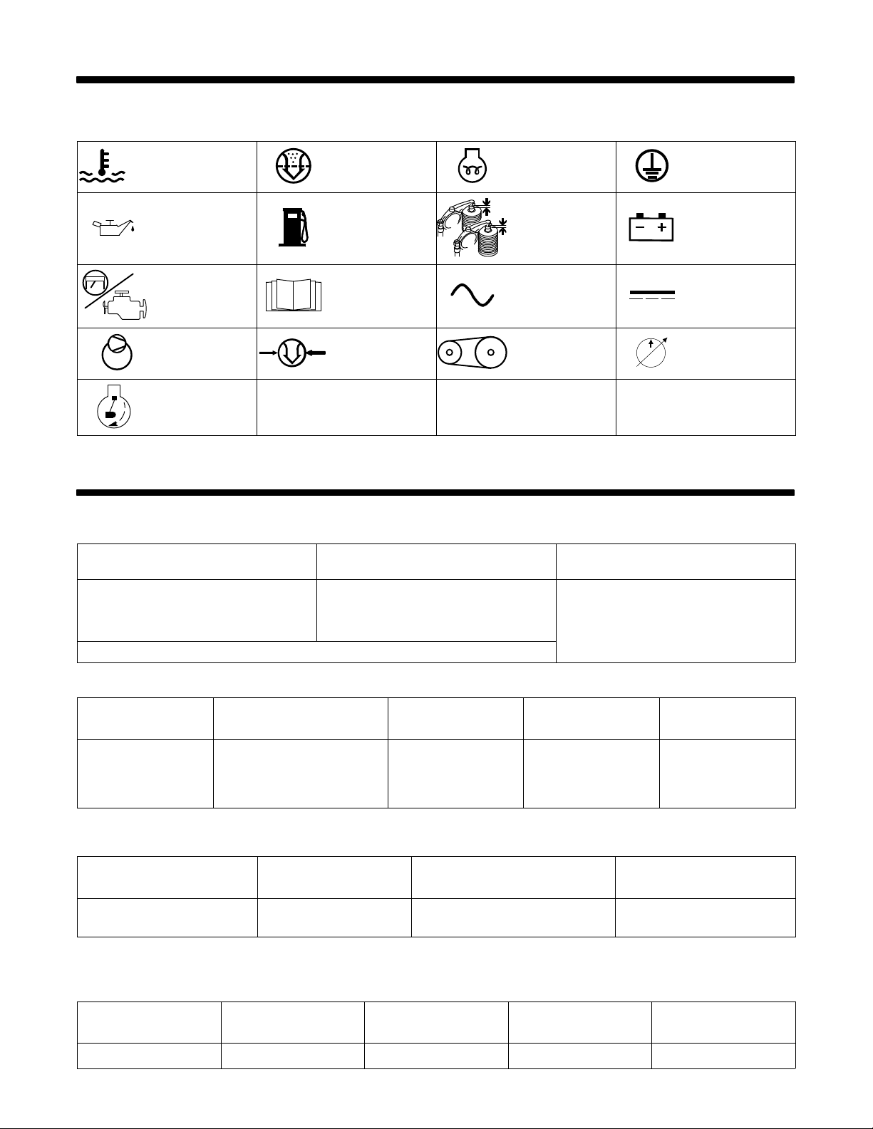
3-1. Symbol Definitions
SECTION 3 − DEFINITIONS
Engine Cooling Engine Air Filter Glow Plugs
Engine Oil Fuel
Engine
Air Compressor Air Pressure Engine Belt Hydraulic Pump
Crank Engine
Read Operator’s
Manual
SECTION 4 − SPECIFICATIONS
4-1. Auxiliary Power And Engine Specifications
Standard Generator Power Rating
Optional EnVertert AC To AC Converter
Power Rating
Check Valve
Clearance
Alternating Current
(AC)
Protective Earth
(Ground)
Battery (Engine)
Direct Current
(DC)
Engine
Single-Phase,
6 kVA/kW at 3600 RPM
120/240 V AC, 50/25 A,
60 Hz, Continuous
Combined Maximum Auxiliary Power Output (Standard Generator And EnVerter) Is 6kVA/kW
2.4 kVa/kW, 20 A at 2600 to 3600 RPM,
300 Watts at 1800 RPM
120 V AC Pure Sine Wave, Continuous
Kubota D1105−E3B, 3−Cylinder, 27.7 HP,
Liquid−Cooled, Diesel Engine w/Electronic
4-2. Air Compressor Specifications
Compressor Type
Rotary Screw
Air Output At Effective
Working Pressure
40 scfm @ 100 psi (1.13 m
−1
min
100% Duty Cycle, 3600 RPM
@ 689 kPa),
3
Range: 90−175 psi
(620−1206 kPa)
Factory set at 120 psi
Pressure
(827 kPa)
Safety Relief
Valve Setting
Auto Shutoff: 200 psi
(1379 kPa)
Pressure Relief: 200 psi
(1379 kPa)
4-3. Hydraulic Specifications (Models With Hydraulic Power Source)
Pump Type
Variable Displacement Piston
*Dependant on system cooling capacity.
8.5 GPM at 3000 psi at 3200
Rated
Output
RPM, 50% Duty Cycle*
Maximum Pressure Maximum Flow Rate
3500 psi (241.3 bar) 20 GPM (75.7 lpm)
4-4. Sound Level Table
Governor
Air Compressor
Oil Capacity
2 qt (1.9 L)
Idle Speed
1800 rpm
Air Compressor On 63 dB 68 dB 73 dB 75 dB
OM-240 113 Page 12
2600 rpm 3200 rpm 3600 rpm
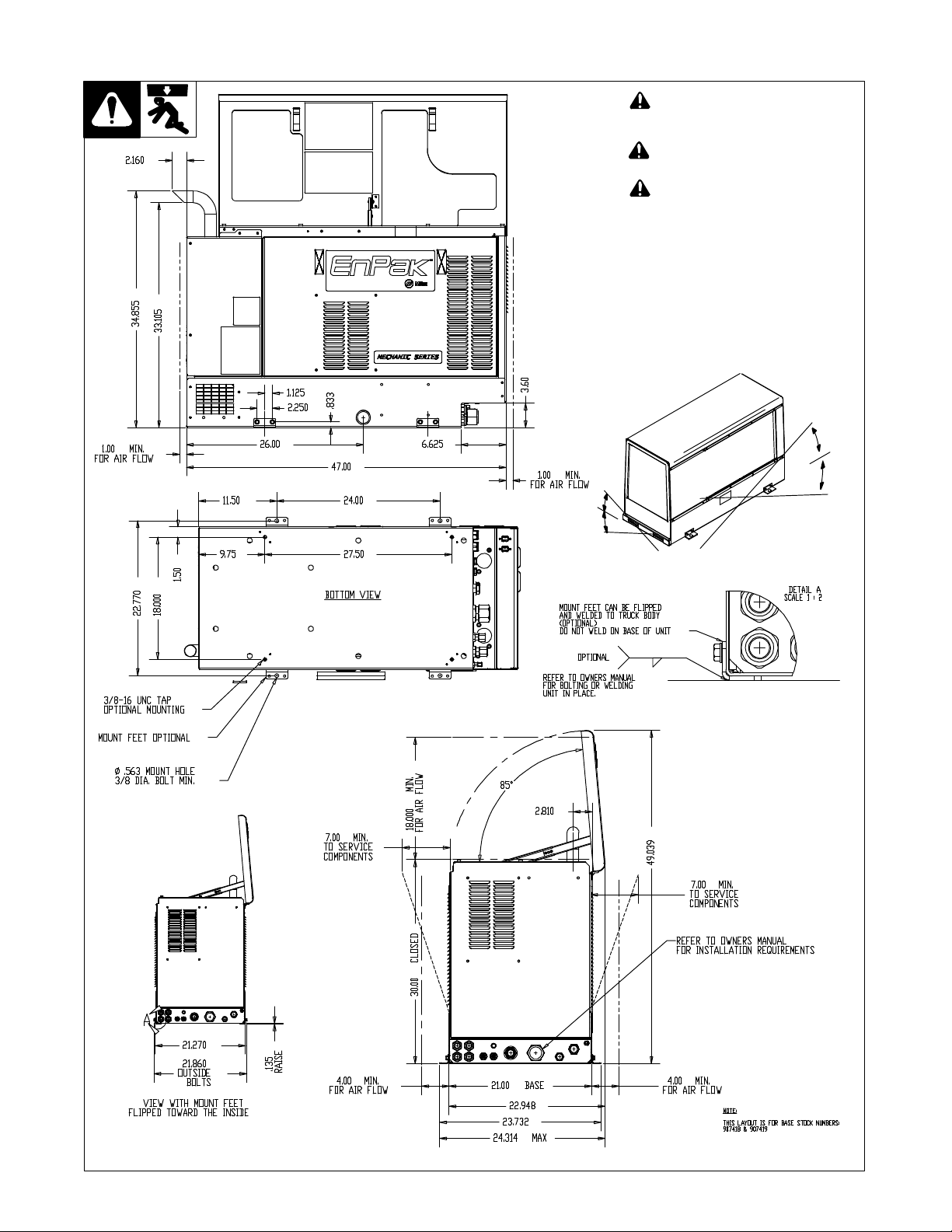
4-5. Dimensions, Weights, and Operating Angles
! Do not exceed tilt angles or engine
could be damaged or unit could
tip.
! Do not move or operate unit where
it could tip.
! Do not operate suspended from
lifting eye.
Weight: 870 lb (390 kg)
767 lb (348 kg) Without
Hydraulic Power Source
925 lb (419 kg) Fully Equipped
W/Packaging
Lifting Eye Weight Rating: 1000 lb (454
kg)
15°
15°
15°
15°
287 139-E
OM-240 113 Page 13
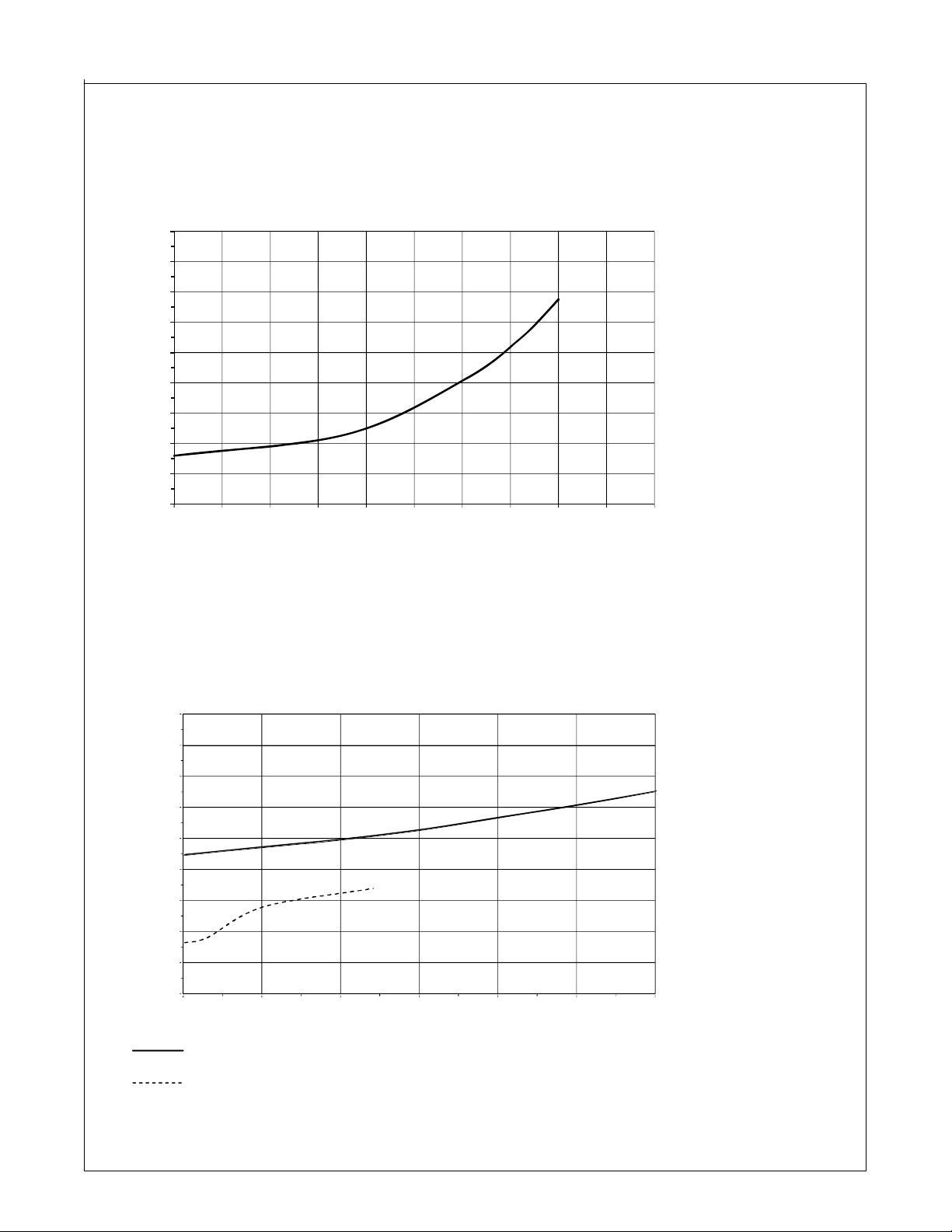
4-6. Fuel Consumption Curves
Compressor
1.80
1.60
1.40
1.20
1.00
0.80
0.60
U. S.. GAL./HR.
0.40
0.20
0.00
0 5 10 15 20 25 30 35 40 45 50
CUBIC FEET PER MINUTE (CFM)
Auxiliary Power
1.80
1.60
1.40
1.20
1.00
0.80
U. S.. GAL./HR.
0.60
0.40
0.20
0.00
0.0 1.0 2.0 3.0 4.0 5.0 6.0
AUXILIARY POWER IN KILOWATTS
Standard Auxiliary Power
Optional EnVertert Auxiliary Power
. Combined maximum auxiliary power output
(standard generator and EnVerter) is 6kVA/kW.
243 168-A / 243 169-A
OM-240 113 Page 14
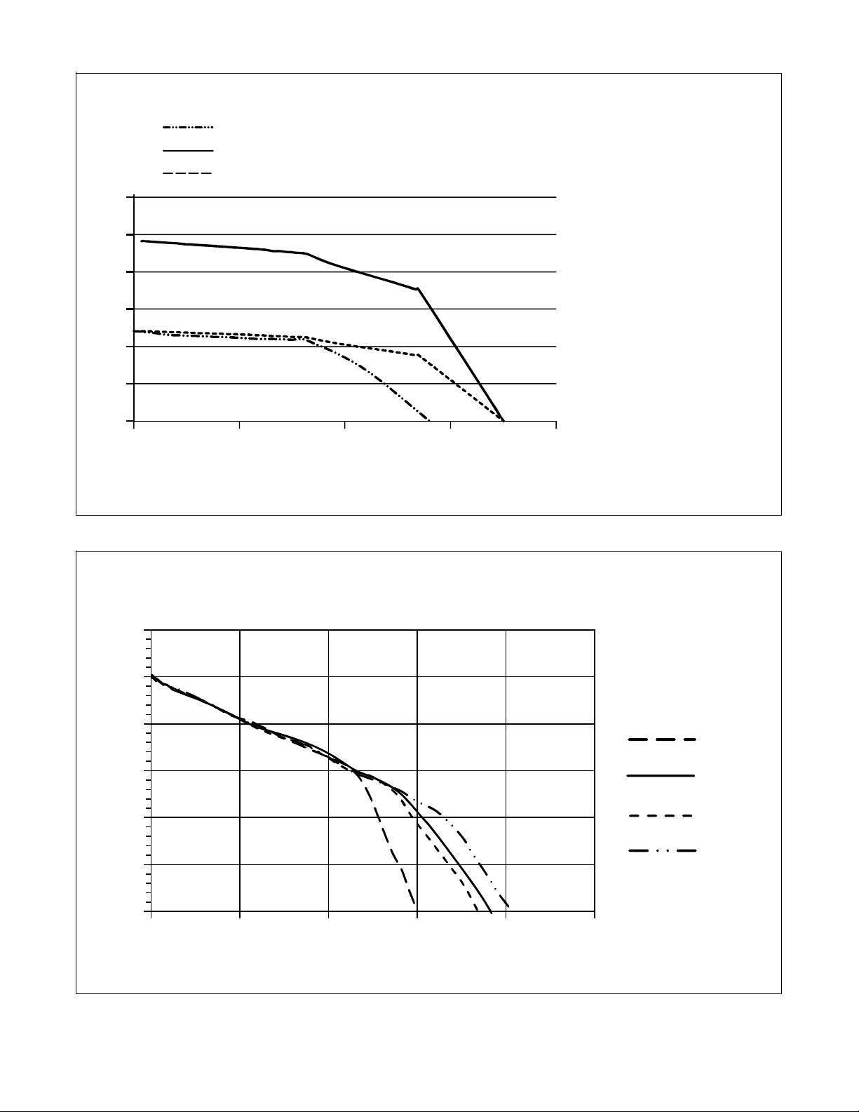
4-7. Auxiliary Power Curves
EnVertert Power
240 VAC Auxiliary Power
120 VAC Auxiliary Power
300
250
200
150
VOLTS
100
50
0
20 40 60 800
. Combined maximum
auxiliary power output
(standard generator and
EnVerter) is 6kVA/kW.
AMPS
The AC generator power curves
show the generator power available
in amperes.
The EnVertert power curve shows
the power available in amperes.
Tools and motors are designed to
operate within 10% of 120/240
VAC.
. When the EnPak is running at
1800 RPM, the voltage output
of the generator is too low to activate some electric machines
that require the full 120 VAC or
240 VAC for operation. If the
electric machine that you are
using is not recognized as a
load by the EnPak, and does
not turn on, place the EnPak in
high speed. This will bring the
output of the generator up to
the normal 120 VAC or 240
VAC level, and the machine
that is plugged into the generator should work normally. This is
for the standard generator
power only, and does not apply
to the EnVerter power output
which is 120 VAC regardless of
engine RPM.
4-8. Alternator Power Curve
15
14.5
14
13.5
VOLTS
13
12.5
12
0 20 40 60 80 100
242 594-A
The alternator volt−ampere curve
shows the available alternator output at various engine rpm.
1800 RPM
3200 RPM
2600 RPM
3600 RPM
. Combined maximum
auxiliary power output
(standard generator and
EnVerter) is 6kVA/kW.
AMPS
242 595-A
OM-240 113 Page 15
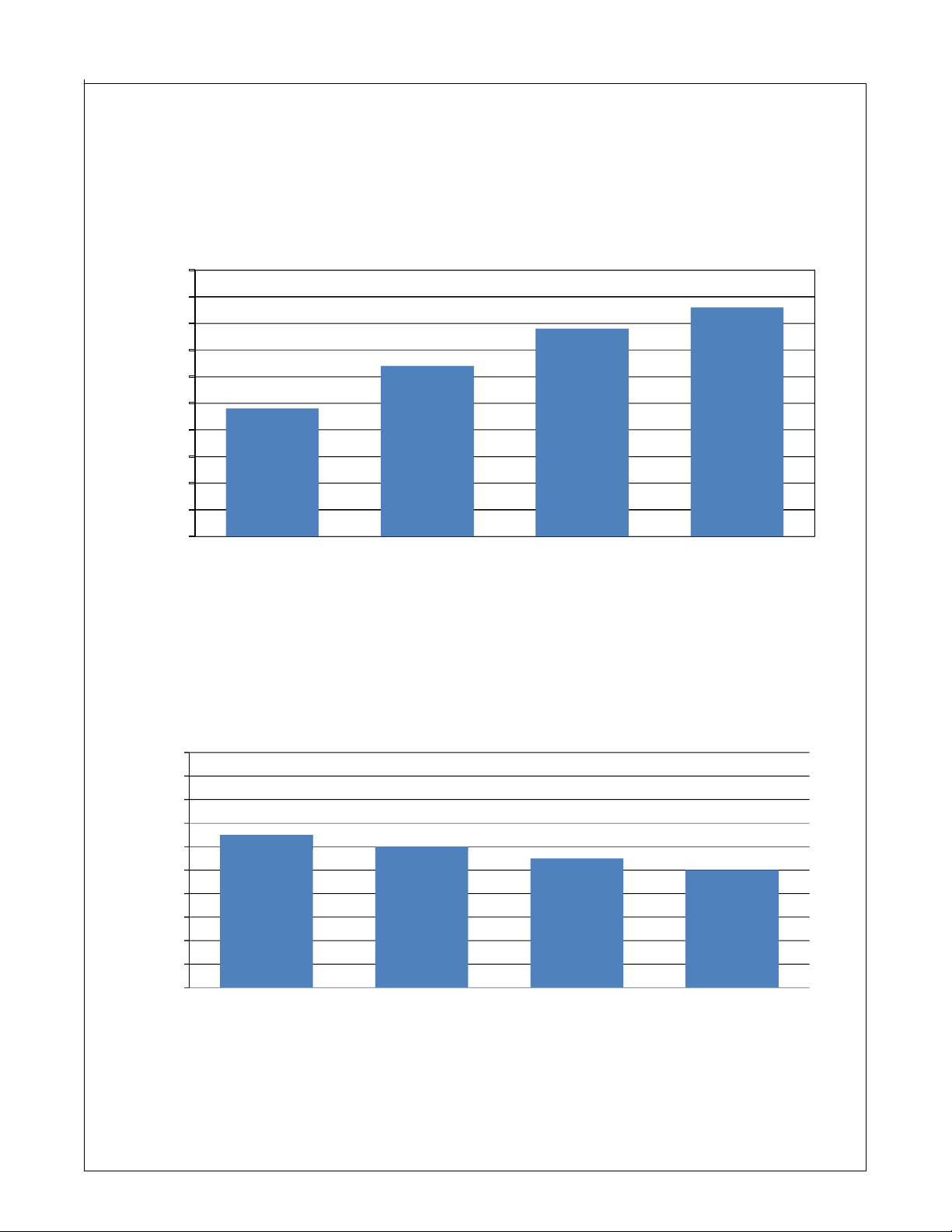
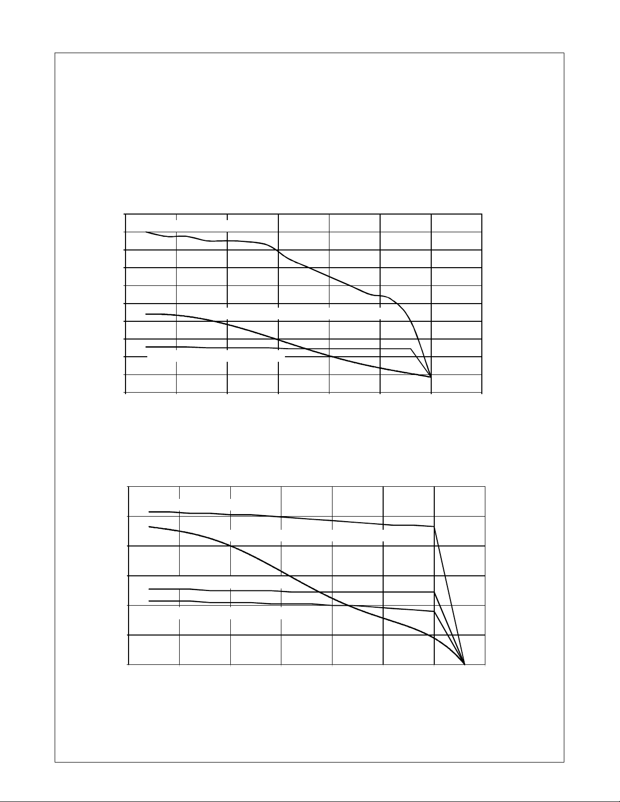
4-9. Air Compressor Curves
50
CFM VS ENGINE RPM
45
40
35
30
25
24
20
15
10
5
CUBIC FEET PER MINUTE (CFM)
0
1800 2600 3200 3600
50
48
46
44
42
43
40
38
36
34
32
CUBIC FEET PER MINUTE (CFM)
30
100 125 150 175
32
ENGINE SPEED (RPM)
CFM VS PSI
42
PRESSURE (PSI)
41
43
39
40
OM-240 113 Page 16
Ref. 220 807−A
4-10. Hydraulic Pressure Curves (Models With Hydraulic Power Source)
. Curves are typical. Output will
vary depending on system
pressure losses to load sense
pressure location.
Fluid: ISO 32 Hydraulic Oil
Fluid Temperature: 49° C (120° F)
Load Sense Pressure:
Closed Center − 400 PSID
(27.6 bar)
Open Center − 200 PSID (13.8
bar)
Closed Center
20.0
18.0
16.0
14.0
12.0
Hydraulic Load Only
10.0
8.0
FLOW (GPM)
6.0
4.0
2.0
0.0
12.0
10.0
8.0
6.0
FLOW (GPM)
4.0
Hydraulic Load Only − Manual Mode
0 500 1000 1500 2000 2500 3000 3500
Hydraulic Load Only
Hydraulic Load Only − Manual Mode
Hydraulic Load Only − 1800 RPM (Outriggers)
Hydraulic +40 CFM @ 100 PSI Compressor Load
PRESSURE (PSI)
Open Center
Hydraulic +40 CFM @ 100 PSI Compressor Load
2.0
0.0
0 500 1000 1500 2000 2500 3000 3500
PRESSURE (PSI)
242 506-A / 242 507-A
OM-240 113 Page 17
SECTION 5 − PRESTART CHECKS
5-1. Hydraulic System Prestart Checks (Models With Hydraulic Power Source)
NOTICE − Ensure hydraulic system is properly connected with valves open before starting unit. Damage will result if unit is run before hydraulic system
is complete. Hydraulic pump does not disengage via clutch.
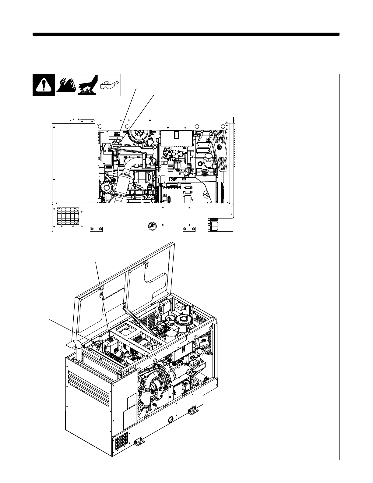
5-2. Engine Prestart Checks
Check all fluids daily. Engine must be
2
1
3
4
cold and on a level surface. Unit is
shipped with 10W30 engine oil.
. Follow run-in procedure in engine
manual.
. This unit has a low oil pressure
shutdown switch. However, some
conditions may cause engine damage before the engine shuts down.
Check oil level often and do not use
the oil pressure shutdown system
to monitor oil level.
Open top cover and service side door.
1 Oil Dipstick
2 Oil Fill
3 Coolant Overflow Bottle
4 Radiator Cap
Fuel
Be sure fuel connections are made and
tight. Be sure fuel tank utilized for unit
operation is full.
Coolant
Check coolant level in radiator and
overflow bottle. If coolant is below Low
level in overflow bottle, add coolant until
level in bottle is between Low and Full
levels. If overflow bottle coolant level
was low, check coolant level in radiator.
Engine Oil
Check oil with unit on level surface. If oil
is not up to full mark on dipstick, add oil
(see maintenance label).
Use remote panel to determine hours
until next recommended oil change
(see Section 6-1).
. For cold weather starting informa-
tion, see Section 6-6.
Keep battery in good condition.
Store battery in warm area.
Use correct grade oil for cold
weather.
Continue initial system checks, see
Section 5-3.
OM-240 113 Page 18
805 444
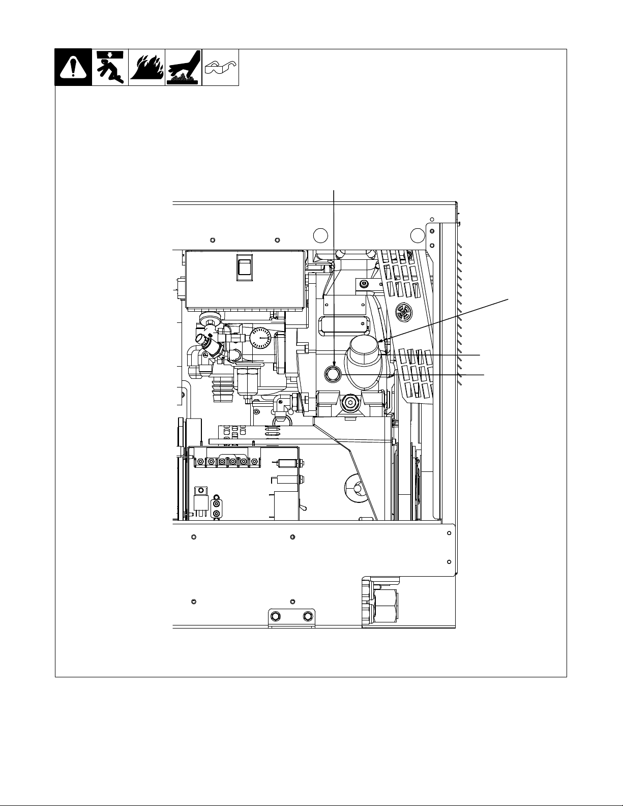
5-3. Compressor Prestart Checks
. The compressor is equipped with high
oil temperature shutdown. High oil
temperature can be caused by low oil
or hot air recirculation.
. Do not open oil fill cap until unit has
been off for 10 minutes. Do not open
while running.
NOTICE − Do not mix oil types. Do not
overfill.
1 Air Compressor Oil Fill Cap
Hand tighten oil fill cap. Using excess
force can damage o−ring.
2 Air Compressor Oil Sight Hole
2
The unit is shipped with oil in the compressor reservoir. Minimum oil level is half
way up the sight hole. Maximum oil level is
in threaded area of oil fill pipe. Check level
frequently. If oil needs to be added, be
sure unit is off for 10 minutes before removing fill cap.
1
. Minimum com-
pressor oil level
is half way up
the sight hole.
Maximum oil
level is in
threaded area
of oil fill pipe.
805 444
OM-240 113 Page 19
SECTION 6 − OPERATION
O
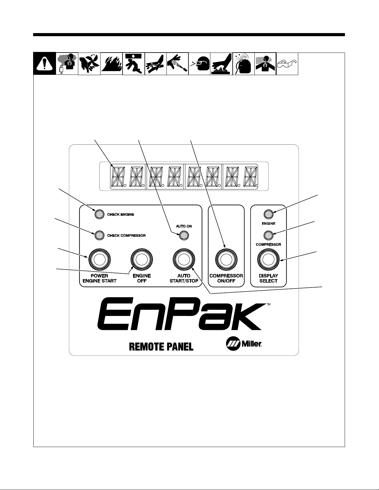
6-1. Remote Panel (Use With Section 6-2)
1
2
3
7
8
4
11
5
6
10
9
OM-240 113 Page 20
248 998

6-2. Remote Panel Operation (Use With Section 6-1)
1 Alpha−Numeric Display
During the Auto Start/Stop mode start se-
quence, the following appears:
SYSTEMon
STARTING
GLOWPLUG
CRANKING
. STARTING and GLOWPLUG may
switch order depending on ambient
temperature.
During the manual mode start sequence,
the following appears:
SYSTEMon
GLOWPLUG
GLOWdone
CRANKING
See Section 6-4 for error messages that
appear.
2 Check Engine LED
Lights when display is showing an engine
error.
If an engine error occurs and the engine
shuts down, the error will be stored in
memory. If the display has already turned
off, press the Power button once to activate
the Remote Panel. If the error is in memory,
the display will read ERROR and after a
few seconds will flash the error code. See
Section 6-4 for error messages that appear.
To erase the error, press and hold the Display Select push button until the display
reads SYSTEMon, and the indicator is off.
The display will now cycle normally when
the Display Select push button is pushed.
3 Check Compressor LED
Lights when display is showing a com-
pressor error.
4 Auto On LED
Lights when Auto Start/Stop mode is se-
lected.
5 Engine LED
Lights when display is showing engine related information.
6 Compressor LED
Lights when display is showing com-
pressor related information.
7 Power Engine Start Push Button
Press and release to turn on power to the
display only. This allows access to the display menu.
When Auto Start/Stop is selected (Auto On
LED is lit). Press and release the Power
Engine Start push button two times. The
first press and release will power up the
control system and the second press and
release will initiate the automatic starting
sequence. The Engine Off push button can
be pressed at any time to stop the sequence.
In manual mode, press and release the
Power Engine Start push button once to
power up the control system, then press
and release the button to start the glow
plug operation. When the display shows
GLOWdONE, press and hold the push button to crank the engine and complete the
starting sequence. The starter will disengage at a predetermined RPM based on
the ambient temperature.
With engine running, press and release to
toggle between low speed and high speed.
The display will flash HIGH SPd when engine is locked in high speed.
8 Engine Off Push Button
Press when engine is running to stop en-
gine, or to stop the automatic start sequence.
9 Auto Start/Stop Push Button
Press and release the Auto Start/Stop
push button to toggle between automatic
and manual control.
When the automatic mode is selected, the
Auto On LED lights and display reads ENAbLEd.
While the display shows ENAbLEd, press
and hold the push button to change the
auto stop timer (range of two to 30
minutes). This time is placed in memory
and is remembered the next time the EnPak is started.
When the system is placed in manual
mode, the display shows dISAbLEd and
the Auto On LED is off.
10 Display Select Push Button
Press and release to cycle through the fol-
lowing displays:
RPM
Battery voltage
Current fuel usage (Gallons Per Hour)
Engine hours
Engine maintenance hours (Counts down
from 400 hours)
Engine temperature
Compressor hours
Compressor maintenance hours (Counts
down from 500 hours)
. Maintenance hours initially count
down from 50 hours. Complete maintenance required after first 50 hours of
operation according to Section 8.
. Current fuel usage is for reference
only. Variables such as ambient temperature, altitude and fuel blend affect
actual usage.
11 Compressor On/Off Push Button
When engine is running, press twice to turn
compressor on or off. When turned on, engine will speed up to 2600 RPM for 5
seconds, and then return to 1800 RPM.
This indicates the compressor is on.
When engine is not running, Press and release to display SET MIN. When SET MIN
is displayed, press and hold to increment
minimum pressure setting.
. Compressor minimum pressure is set
through the control program. Compressor maximum working pressure is
set at the Air Pressure Regulator
(P−PRV). See Section 7-1.
6-3. Safety Interlock
Models With Hydraulic Power Source: The safety interlock system must be engaged before the EnPak engine can be started Contact dealer for
detailed description of supplied system.
Models Without Hydraulic Power Source: The safety interlock system requires 12 volts DC be supplied from the accessory position of the truck
ignition switch to pin 5 of RC13. Splice into supplied plug and wire.
. Test safety interlock monthly, see Section 8-4.
OM-240 113 Page 21

6-4. Operation And Error Messages
1
1 Alpha−Numeric Display
The following operational messages
may appear:
CHNG OIL
Indicates an oil change is needed. This light
flashes after the first 50 hours of operation
and then at normal oil change intervals
thereafter.
If CHECK ENGINE LED is on, engine oil
change time interval has counted down to
zero, indicating it is time to change engine
oil.
To reset display after oil change, see Section 8-5.
If CHECK COMPRESSOR LED is on,
compressor oil change time interval has
counted down to zero, indicating it is time to
change compressor oil.
To reset display after oil change, see Section 8-7.
HIGH SPd
Indicates engine is locked in high speed.
With engine running, press Power/Start
button to toggle speed.
AUTOSTOP
This will flash briefly when unit is in Auto On
mode and the engine stops automatically.
The following error messages may appear:
. If error message appears, consult
troubleshooting section for remedial
actions.
Hi TEMP
Indicates high compressor temperature if
CHECK COMPRESSOR LED is on.
OVErPRES
Indicates the compressor has an over pressure error.
OVErSPEEd
Indicates an engine over speed error.
LOW OIL
Indicates a low oil pressure condition in the
engine.
NoCHARGE
Indicates an alternator problem.
HiTEMP 1
Indicates high engine temperature if
CHECK ENGINE LED is on. The temperature switch has indicated high temperature.
HiTEMP 2
Indicates high engine temperature if
CHECK ENGINE LED is on. The temperature sensor has indicated high temperature.
SPd SENS
Indicates a problem with the engine speed
sensor.
GovCNTRL
Indicates a problem with the engine governor control.
SEN OPEN
Indicates coolant sensor is open.
SENSHORT
Indicates coolant sensor is shorted.
ALTRNATR
Indicates an open condition in the alternator.
248 998
HiVOLTiN
Indicates high input voltage from the battery.
LoVOLTiN
Indicates low input voltage from the battery.
ERROR
If an engine error occurs and the engine
shuts down, the error will be stored in
memory. If the display has already turned
off, press the Power push button once to
activate the Remote Panel. If the error is in
memory, the display will read ERROR and
after a few seconds will flash an error code.
See Table 6-1.
EnVertert Power System
The following messages may appear if the
unit is equipped with the EnVertert power
system.
ENVRT hot
Indicates the EnVerter power system is
overheated.
ENVRT com
Indicates a communication error.
ENVRT ok
Indicates the EnVerter power system is
functioning. Press Power/Start button to
enable.
HYdCAbLE
Indicates problem with crane remote interconnecting cable, plug, receptacle, or adapter harness.
OM-240 113 Page 22

6-5. Auto Start/Stop Operation
2
1
248 998
1 Power Engine Start Push Button
Press the Power Engine Start push button
to turn on the EnPak Remote Panel. The
EnPak warning beeper will beep if the EnPak is in auto start/stop mode.
First Time Engine Start –
Any time that the engine is started, the engine will go to 2600 RPM and continue to
run at that speed until it reaches an operating temperature of 100°F. Once it has
reached that temperature, the auto start/
stop feature is activated if it is enabled. The
EnPak will then automatically shut down
after the specified time the end user sets for
an unloaded condition.
Auto Stop Timeout -
To set the time for the automatic shut down,
press and release the Auto Start/Stop button until the display shows ENAbLEd.
When the display reads ENAbLEd, press
and hold the Auto Start/Stop button, and the
time to shut down will display. Continue to
hold the button and it will increase in steps
of 1 minute up to a maximum of 30, and then
start over at 2 again. Release the button
when the desired time is reached.
First Start Of The Day –
In manual mode, the EnPak will start with
manual pushes of the Remote panel start
button, or the Start switch on the crane
pendant. In automatic mode using the Remote panel, the first start of the day requires
2 successive push and release operations
of the Power Engine Start push button. In
automatic mode using the Crane pendant,
the first start of the day requires a press and
hold of the Power Engine Start push button,
or 2 successive push and release operations of the switch. Once the warning beeper is on, the engine will continue to automat-
ically start unless the process is stopped by
pushing the Engine Off button on the Remote Panel or the Engine Stop switch on
the crane pendant.
Automatic Re-Start Of EnPak
. The system cannot detect a generator
load that is applied when the engine is
off.
a) When the engine is turned off automatically, the EnPak control boards are still
functioning. This allows the EnPak to sense
any loads that are applied, so it will restart
the engine when needed. The EnPak will
not shut down if there is a load applied to the
EnPak.
b) The EnPak can be started with one
press and release of the Power Engine
Start push button on the EnPak Remote
Panel, or with one press and release of the
Engine Start switch on the Crane pendant.
c) If the compressor is turned on from the
Crane pendant, the EnPak will automatically start and pump up the air tank.
d) If an air tool is used, and the air compressor is in the on condition, the EnPak will
sense the load and start the engine to pump
up the tank.
e) If a crane switch is toggled, and the proportional trigger pulled, the EnPak will
sense that the crane is required, and automatically start the engine. This will work
only for open center systems that have the
proportional signal available from the
crane. Alternately, the start switch could be
pushed and released one time to start the
engine.
2 Auto Start/Stop Push Button
Auto Start/Stop Enable/Disable −
The auto start/stop feature can be disabled
or enabled, using the Auto Start/Stop push
button on the EnPak Remote Panel. If the
Auto On LED in the center of the display is
lit, the auto start/stop feature is enabled. To
disable the auto start/stop feature, just
press the Auto Start/Stop push button
once. The EnPak Remote Panel will display diSAbLEd, the Auto On LED will turn
off, and the EnPak will function under
manual control. To enable the auto start/
stop feature, press the Auto Start/Stop
push button again, and the Auto On LED
will light up, the EnPak Remote Panel will
display ENAbLEd, and the EnPak will automatically stop after a set time with no load.
Auto Stop –
If the ambient temperature is below 0°F, the
engine will not automatically shut down.
Engine Stop –
If the EnPak engine is turned off using the
Remote Panel Engine Off push button or
the Crane pendant Engine Stop switch, the
EnPak will not turn back on automatically.
Battery Protection – When there is a load
applied to battery and the EnPak shuts
down automatically, the EnPak will restart
when the battery voltage reaches a level
that indicates charging is required. If there
is a heavy battery load applied that drags
the battery voltage low, the beeper will beep
a warning and the display will flash LOW
bATT.
EnVerter Load Less Than 300 W - If there
is a load applied to the EnVerter power
source, that is less than 300 Watts, the EnPak will not sense it at this time, and will
automatically shut down.
Error Reporting / Error Clearing - See
Section 6−4
OM-240 113 Page 23

6-6. Cold Weather Starting And Operation
Cold Weather Starting Procedure
Engine Start
. See Operation Section for additional remote panel operating instructions.
1 Prior to starting the engine verify that all fluids (fuel, engine coolant, engine oil, hydraulic oil, and compressor oil) are to the correct level and grade/
specification for the ambient temperature indicated. If the ambient temperature is below 14°F (−10°C) engine coolant block heaters and hydraulic oil
heaters may be be required prior to the engine start. See chart below for minimum heater times.
2 Turn unit on and initiate the engine glow plugs. See chart below when manually starting the unit from the EnPak service panel.
. All external loads on the engine should be off when starting the engine. The air compressor should be off until the engine has been started and
warmed up.
3 Start engine. If engine fails to start after 10 seconds, turn unit off and repeat start sequence.
4 Allow engine to warm up prior to loading engine, See Note 1A.
. Be sure to warm up engine, not only in the winter, but also in warmer seasons. An insufficiently warmed−up engine can shorten its service life.
OM-240 113 Page 24

VI 120 VI 120 VI 120 VI 120 VI 120 VI 120
160 VI 140 VI 140 VI 140
−−−−−−−−−−
0W −20 5W −30 5W −30 10W −30 10W −30 10W −30 10W −30 10W −30 10W −30 10W −30
Auto/20 sec Auto/20 sec A uto/20 sec Auto/20 sec Auto/10 sec Auto/10 sec A uto/5 sec −−−
1
60 m in. 40 m in. 30 m in. 20 m in. −−−−−−
Full Synthetic 5W −40 5W −40 10W −40 10W −40 10W −40 10W −40 10W −40 10W −40 10W −40
3
ISO 15 ISO 15 ISO 15 ISO 15 ISO 3 2 ISO 32 ISO 32 ISO 32 ISO 46 ISO 46
VI
Mobil 1 ATF Mobil 1 ATF Mobil 1 ATF Mobil 1 ATF Mobil 1 ATF Mobil 1 ATF Mobil 1 ATF Mobil 1 ATF Mobil 1 ATF Mobil 1 ATF
5
intake cooling air. See Engine Troubleshooting Section for trouble shooting over or under coolant temperature.
1 Glow plugs are automatically activated when the unit is turned on from the EnPak remote or crane remote. Times listed are the maximum recommended glow plug times when
starting the EnPak using the manual service panel. Extending the glow plug times beyond those listed can cause damage to the glow plugs and system.
2 For additional engine oil specification see Engine Maintenance Label or Engine Operators Manual.
3 Times listed are for the standard Miller Part No. 300525, Engine Block Heater, 120V. Optional, Miller Part No. 300808, EnPak Subzero Package can be used to integrate the
EnPak coolant system to the vehicles coolant system and effectively reduce or eliminate the need for the engine block heater to preheat the engine coolant.
4 Maximum start−up viscosity limited to 2100cSt, minimum intermittent viscosity limited to 6cSt. Use of a high viscosity index (VI) fluid is recommended to attain the ISO fluid
1A Normal stabilized engine coolant temperatures should be in the range of 160 − 220°F (71 − 104°C). In extreme cold conditions it may become necessary to block a portion of
recommendations listed. Refer to EnPak Technical Bulletin for further details. Never allow fluid temperatures to exceed 160°F during operation (do not exceed 140°F for hand−held
tools).”
5 Optional, Miler Part No. 300546, Hydraulic Reservoir Oil Heater. Necessitated only when oil exceeds maximum start−up viscosity of 2100cSt.”
− Not required.
1A
C −40 −30 −25 −20 −10 0 10203040
F −40 −22 −13 −41432506886104
Am bient Tem perature (At or below)
Engine
2
Glow Plugs
Block Heater
Oil
4
Battery Heater Yes Yes Yes Recomm ended −−−−−−
Oil
EngineW arm−up 7min 5min 5min 3min 2min 1min 1min 1min 1min 1min
Oil Vicosity Index
Hydraulic
Oil
Oil Heater
Compressor
OM-240 113 Page 25
 Loading...