

Miller Edge Operation & Maintenance Manual
OPERATION & MAINTENANCE MANUAL FOR
THE
The Miller® Edge™ and related equipment is designed to provide portable fall protection for workers
subjected to fall hazards during leading edge construction.
WARNING: ALL PERSONS USING THIS EQUIPMENT MUST READ, UNDERSTAND AND
FOLLOW ALL INSTRUCTIONS. FAILURE TO DO SO MAY RESULT IN SERIOUS INJURY OR
DEATH. PREGNANT WOMEN AND MINORS MUST NOT USE THIS PRODUCT.
I211 Rev. C
9720101

I. GENERAL REQUIREMENTS
A. WARNINGS AND LIMITATIONS
Proper precautions should always be taken to remove any obstructions, debris and other
material from the work area that could cause injuries or interfere with the operation of the
system. Also, caution should be taken to ensure all equipment will be clear of all other
recognized hazards and proper ventilation has been provided in the work area before work
begins.
Note: Users should be familiar with pertinent regulations governing this equipment. All individuals
who use this product must be correctly instructed on how to use the system and must read and
understand the following instructions before using the system.
• Only trained personnel should use this system and its components.
• Do not use if the unit or any part of the system appears to be damaged.
• Do not use the system if any components do not operate properly.
• Use in highly corrosive or caustic environments dictates a more frequent
inspection and servicing program to ensure the integrity of the system is
maintained.
• Do not attempt to repair this system.
• Personal fall arrest systems and components subjected to impact loading shall be
immediately removed from service and shall not be used again for employee
protection until inspected and determined by a competent person to be
undamaged and suitable for reuse.
• Employer must provide for prompt rescue in the event of a fall.
• All equipment must be inspected before each use.
• Any component exhibiting deformities, unusual wear, or deterioration must be
immediately discarded.
• This product is designed for personal fall protection. Never use fall protection
equipment for purposes other than which it is designed.
• Never use fall protection equipment for towing or hoisting.
• Always check for obstructions below the work area to make certain the potential
fall path is clear.
• Use only compatible locking snap hooks or locking carabiners with this product.
• Use only approved Miller hardware with this product.
• Do not attempt to move the unit while workers are attached.
• Do not use unit on uneven or sloped surfaces greater than 5% from the horizontal.

B. LIMITATIONS
The Miller® Edge™ is intended for use on horizontal surfaces or surfaces with < 5% grade. The following
limitations must be read, understood and followed before installation can take place.
• FLOOR STRUCTURE: The structure to which the unit is used must be no less than 5/8”
(15.9mm) thick plywood and capable of supporting the weight of the system and the
loads applied by the system in event of a fall. The surface must be even and no greater
than a 5% grade from horizontal.
• SYSTEM CAPACITY: The maximum number of user’s per unit is 2 (two). Only (1) user
per individual anchor point is permitted. The capacities are based on maximum user’s
weight, including tools, clothing etc. of 310 lbs. (140.6 kg) each or 620 lbs.
(281.2 kg) total weight. Warning: Maximum capacity for each attachment point is 310
lbs. (140.6 kg). Do not exceed this weight per individual attachment point.
• COMPONENT COMPATIBILITY: The Miller® Edge™ is designed for use with Miller
retractables and approved components only. Substitution or replacement with nonapproved components will endanger the compatibility within the system and may affect
the reliability and safety of the total system. It is recommended the user(s) attaching to
this device must only use Miller retractable lifelines and approved compatible connectors.
• LIFTING RINGS: The lifting rings are to be used solely for lifting the unit up by crane or
other means of a lifting or hoisting type structure to locate the unit on to the working
surface. Do not use the lifting rings for fall protection.
• MOVING THE SYSTEM: Always disconnect before attempting to move the unit. Move
the unit by using the horizontal handle at the rear of the unit using a pushing type motion.
Steering the unit can be accomplished by using the handle located on the vertical boom.
(Ref. fig.1) Never expose a worker(s) to a fall hazard by pulling the unit from the handles
located on the vertical boom or from the anchorage points while connected to the unit.
• INSTALLATION DISTANCE: Minimum installation distance from the front of the unit to
the leading edge is 2 ft. Minimum installation distance from the side of the unit to the side
leading edge is 3 ft. (Ref. fig. 10)
• CONNECTORS: Connectors used within the system must be able to support a minimum
of 5,000 lbs. Non-approved, non-compatible components may cause accidental
disengagement (roll-out). Only self-locking, self-closing connectors are recommended by
Dalloz Fall Protection.
• SURFACE GRADE: The Miller
surfaces
elevation.
<
than a 5% elevation. Warning: Do not use on surfaces greater than 5%
®
Edge™ is designed for use on horizontal surfaces or
• WORKING DISTANCE: The maximum working distance forward, measuring from the
vertical boom is 26 ft. The maximum working distance from the side of the unit,
measuring from the vertical boom is 12 ft. Ref. figure 10. WARNING: DO NOT EXCEED
WORKING DISTANCE REQUIREMENTS.
• ANCHORAGE HEIGHT: To determine the anchorage height of the unit measure from the
eyebolt to the surface the unit is supported with. Ref. fig. 9.
II. INSTALLATION
Before installation, it is recommended that the support structure meets or exceeds requirements specified
General Requirements, Part B Limitations.
in
Before installation of this equipment, User must read and understand all instructions and carefull
inspect all equipment to ensure that it is in usable condition. User should familiarize his/herself
with all components of this
ection for further details.
s
WARNING: Do not use if any damaged or missing parts are detected.
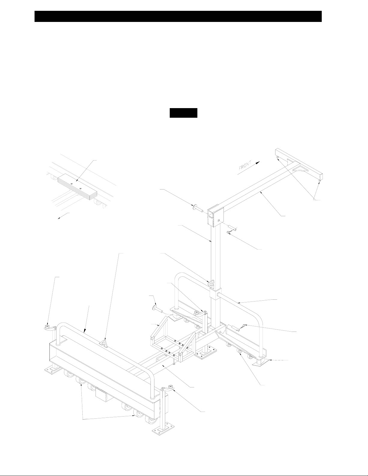
A. PART IDENTIFICATION:
Optional Equipment *
9081WT/300LB
*
Counter Weights
system. Also, check for missing or damaged parts. Refer to inspection
Push Pin
Fig. 1
y
Anchor
Points
Front of Unit
Brake Jack
Pushing
Handle
Lifting Rings
Push Pin
9081MRMB
*
Vertical Boom
Brake Jack
Main Body
Horizontal Boom
Hitch Pin
Steering handles
Hitch Pin
Stabilizer
Swiveling Casters
Swiveling Casters
Brake Jack
B T
. SYS EM COMPONENT INSTALLATION:
Unit As
U
NOTE: For safety and ease of assembly, it is recommended that two or more workers
a
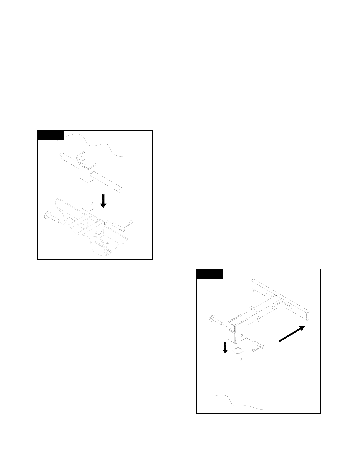
Vertical Boom Installation: Refer to fig. 2. for typical installation.
Fig. 2
H
installation.
Step 1. With the anchorage points facing the front of the
unit, place the Horizontal B
b
Step 2. Install the Push Pin through the horizontal boom
and ensure that the pin goes through both sides of the
Vertical Boom and exits out t
b
WARNING: Ensure that the Hitch Pin has been
installed thro
H
D
sembly Overview:
Step 1. Install Vertical Boom Assembly.
Step 2. Install Push Pin and Hitch pin.
Step 3. Install Horizontal Boom Assemb
ly.
Step 4. Install Push Pin and Hitch pin.
Step 5. Inspect the installation and components of the unit before each use.
nit Assembly Details:
ssembly and installation of the system assemble the vertical and horizontal booms.
Step 1. With the Lifting Ring facing toward the back end of
the unit, install the Vertical Boom down inside through the
handle box and d
own inside the main body at the location
shown in fig. 2.
Step 2. Install the Push Pin through the main body of the
unit and ensure that the pin goes through both sides of the
Vertical Boom and exits
body. Install the Hitch Pin.
out the other side of the main
WARNING: Ensure that the Hitch Pin has been
installed through the Pu
H PIN IS MISSING.
HITC
sh Pin. DO NOT USE UNIT IF
sembly: Reverse above procedures.
Disas
Fig. 3
orizontal B
oom Installation: Refer to fig. 3. for typical
oom over the top of the vertical
oom as shown in fig. 3.
he other side of the horizontal
oom. Install the Hitch Pin.
ugh the Push Pin. DO NOT USE UNIT IF
ITCH PIN IS MISSING.
isassembly: Reverse above procedures.
trained in the
Front
B. SYSTEM COMPON
y
9081MR
Warning
supplied could result in serious injury or death.
ote: Inspect for loose or damaged components prior to use. If any damage or loose hardware is
N
etected do not use system.
d
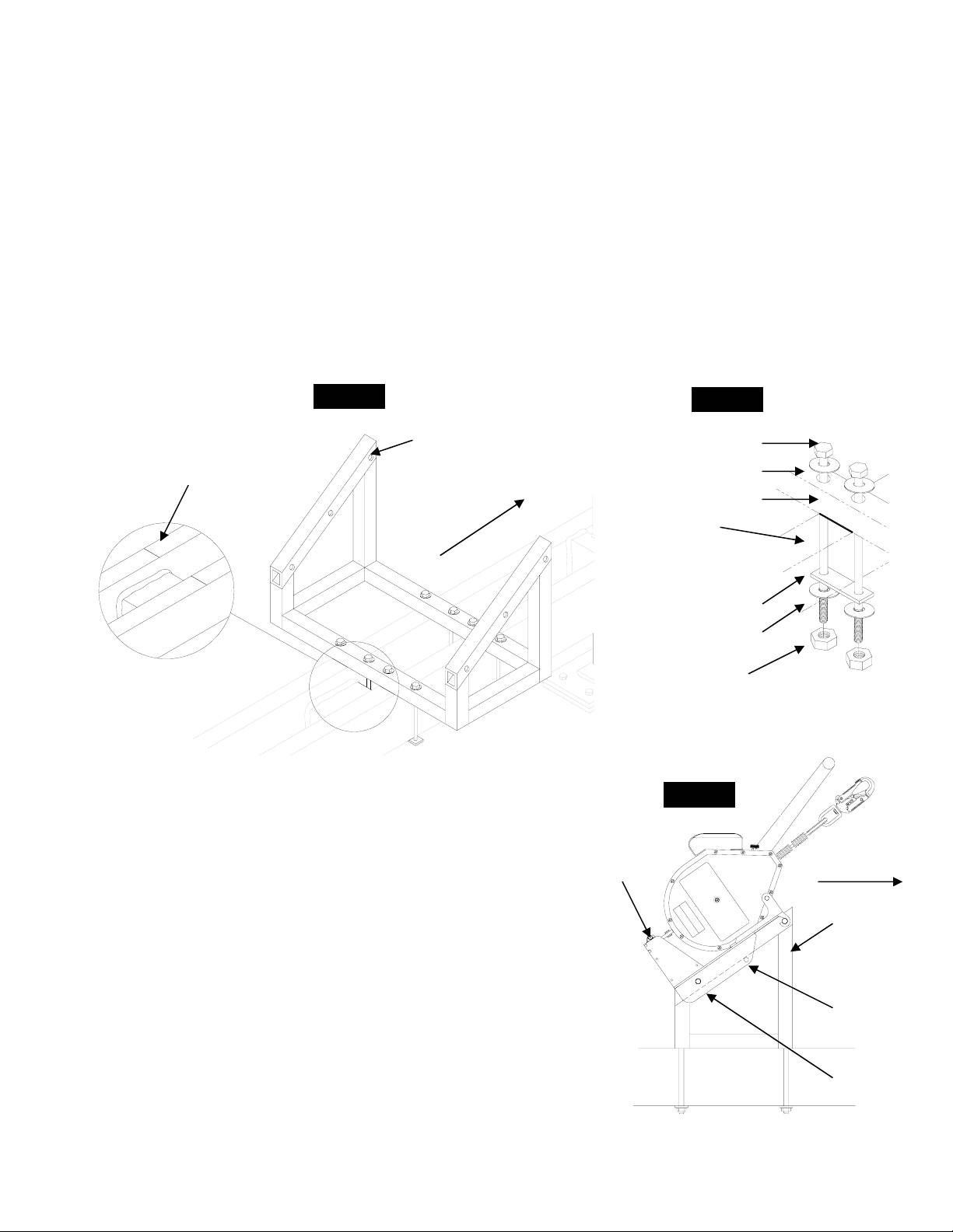
MB Installation:
Step 1.
the unit. Ref. fig. 4.
Step 2. Align and center the back of the bracket with the installation marks. Ref. figs. 4 & 5.
Step 3.
side of the frame rails. Ref. fig. 5
Step 4.
fig. 5. Caution: Over tightening will cause damage to retaining strap.
Locate the Installation marks stamped into the main frame rails located in the center of
Install a flat washer on the bolt, feed the bolt through both holes of the bracket along each
Install retaining strap, flat washer and hex nut. Tighten until snug then add 1/2 turn. Ref.
: All bolts must be installed to the above procedures prior to use. Failure to install all hardware
ENT INSTALLATION (cont.)
Fig. 4
Fig. 5
9081MRMB
Installation
Marks
stalling the MightEvac Retrieval Units to the 9081MRMB:
In
Step 1. Place the MightEvac with attached bracket to t
on shown and align the bottom holes. Ref. fig. 6
locati
Step 2. Insert the bottom pin c
the tubin of the 9081MRMB.
g
ompletely through both the bracket and
9081MRMB
Front of Unit
he 9081MRMB at the
Step 3. Insert the second pin through the top installation hole of the bracket
passing under the 9081MRMB bracket ensuring the pin is completely through
both sides of the MightEvac bracket. Ref. fig. 6
Step 4. Open the pulley sheave by rotating half
on to the wheel of the pulley and close the pulley sheave.
of the sheave. Place the cable
5. Ensure that cable is over the steering handles of thStep
e Edge unit and not
under, attach the carabiner to the pulley sheave and connect to the anchorage
point. (Eyebolts) Ref. fig. 1
Disassembly: Reverse above procedures.
Warning: Both pins must only be installed at location shown. Failure to install
pins at these locations could re
Note: Ensure the unit retaining pin is ins
sult in serious injury or death.
talled before using the system
7/16” x 9” Bolt
7/16” Flat Washer
1MRMB Bracket
908
Frame Rail
Retaining Strap
7/
16” Flat Washer
7/16” Hex Nut
Unit
Retaining Pin
Fig. 6
Fr ge
ont of Ed
stem
S
9081MRMB
Top
Ins on
tallati
Hole
Bottom
Installation
Hole
 Loading...