

Miller DELTAWELD 302, DELTAWELD 402, DELTAWELD 452, DELTAWELD 602, DELTAWELD 652 Owner's Manual
...
July 1996 Form: OM-223H
Model
Welding
Range
OCV
Rati
Effective With Serial No. KG141349
OWNER’S
MANUAL
Deltaweld® 302, 452, 652 (60 Hz)
Deltaweld® 402, 602, 852 (50/60 Hz)
CV/DC Welding Power Sources For GMAW, FCAW, SAW Welding, And CAC-A Cutting And Gouging
Model
300
Amp
450
Amp
650
Amp
*While idling
( ) Indicates specification differences for CE models
cover_om 4/95 − ST-800 453 PRINTED IN USA
Rated
Welding
Output
300 A @ 32
(29) Volts
DC, 100%
Duty Cycle
450 A @ 38
(36.5) Volts
DC, 100%
Duty Cycle
650 A @ 44
Volts DC,
100% Duty
Cycle
Voltage
Range
DC
10 − 32
10 − 38 48 21M
10 − 44 54 21M --
Max
OCV
DC
38
(43)
21M --
Amperes Input at Rated Load Output, 50 or 60 Hz,
IP
ng
200 V 230 V 380 V 400 V 440 V 460 V 575 V KVA KW
42
3.2*271.8*251.7*231.6*211.6*171.3*
72
3.2*632.7*392.6*372.2*332.1*321.4*251.1*
96
3.2*583.3*543.0*502.8*481.6*381.3*
Three-Phase
© 1996 MILLER Electric Mfg. Co.
16.9
1.26*
25.1
1.09*
38.2
1.26*
12.9
0.21*
21.1
0.26*
34.2
0.35*

Declaration of Conformity For
European Community (CE) Products
NOTE
Manufacturer’s Name: Miller Electric Mfg. Co.
Manufacturer’s Address: 1635 W. Spencer Street
This information is provided for units with CE certification (see rating label on unit.)
Appleton, WI 54914 USA
Declares that the product: Deltaweld® 402, 602, And 852
conforms to the following Directives and Standards:
Directives
Electromagnetic compatibility Directives: 89/336/EEC, 92/31/EEC
Low Voltage Directive: 73/23/EEC
Machinery Directives: 89/392/EEC, 91/368/EEC, 93/C 133/04, 93/68/EEC
Standards
Safety Requirements for Arc Welding Equipment part 1: EN 60974-1: 1990
Arc Welding Equipment Part 1: Welding Power Sources: IEC 974-1
(April 1995 − Draft revision)
Degrees of Protection provided by Enclosures (IP code): IEC 529: 1989
Insulation coordination for equipment within low-voltage systems:
Part 1: Principles, requirements and tests: IEC 664-1: 1992
Electromagnetic compatibility (EMC) Product standard for arc welding equipment:
EN50199: August 1995
European Contact: Mr. Luigi Vacchini, Managing Director
MILLER Europe S.P.A.
Via Privata Iseo
20098 San Giuliano
Milanese, Italy
Telephone: 39(02)98290-1
Fax: 39(02)98281-552
dec_con1 10/95

SECTION 1 − DEFINITIONS
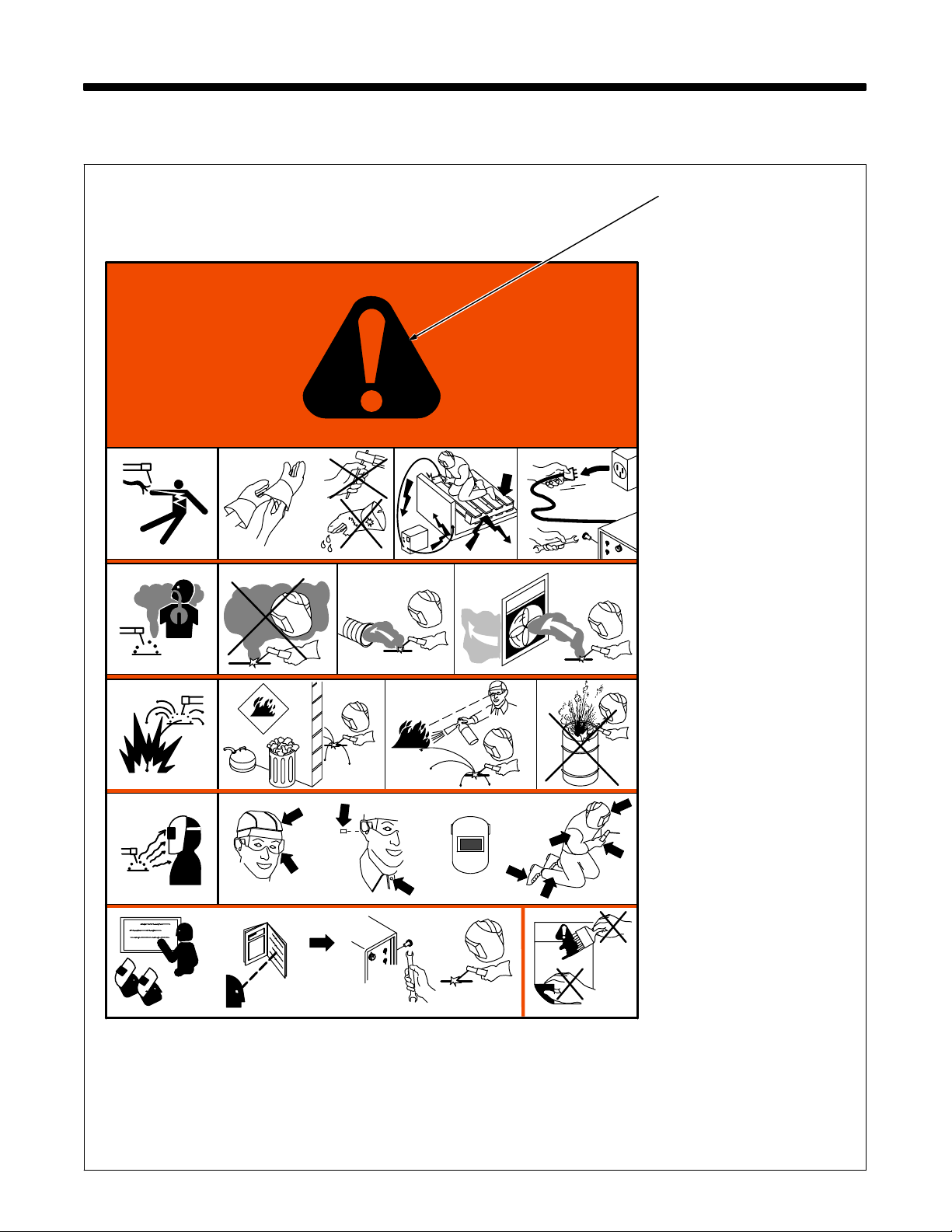
1-1. Warning Label Definitions
1 1.1 1.2
2
3 3.1 3.2 3.3
4 4.1
2.1
+
2.2
2.3
+
+
1.3
Warning! Watch Out! There are
possible hazards as shown by the
symbols.
1 Electric shock from welding
electrode or wiring can kill.
1.1 Wear dry insulating gloves.
Do not touch electrode with
bare hand. Do not wear wet or
damaged gloves.
1.2 Protect yourself from electric
shock by insulating yourself
from work and ground.
1.3 Disconnect input plug or
power before working on
machine.
2 Breathing welding fumes can
be hazardous to your health.
2.1 Keep your head out of the
fumes.
2.2 Use forced ventilation or local
exhaust to remove the fumes.
2.3 Use ventilating fan to remove
fumes.
3 Welding sparks can cause
explosion or fire.
3.1 Keep flammables away from
welding. Do not weld near
flammables.
3.2 Welding sparks can cause
fires. Have a fire extinguisher
nearby, and have a
watchperson ready to use it.
3.3 Do not weld on drums or any
closed containers.
4 Arc rays can burn eyes and
injure skin.
4.1 Wear hat and safety glasses.
Use ear protection and button
shirt collar. Use welding
helmet with correct shade of
filter. Wear complete body
protection.
5 Become trained and read the
instructions before working on
the machine or welding.
6 Do not remove or paint over
(cover) the label.
5 6
+
S-176 254-A
1/96
OM-223 Page 9
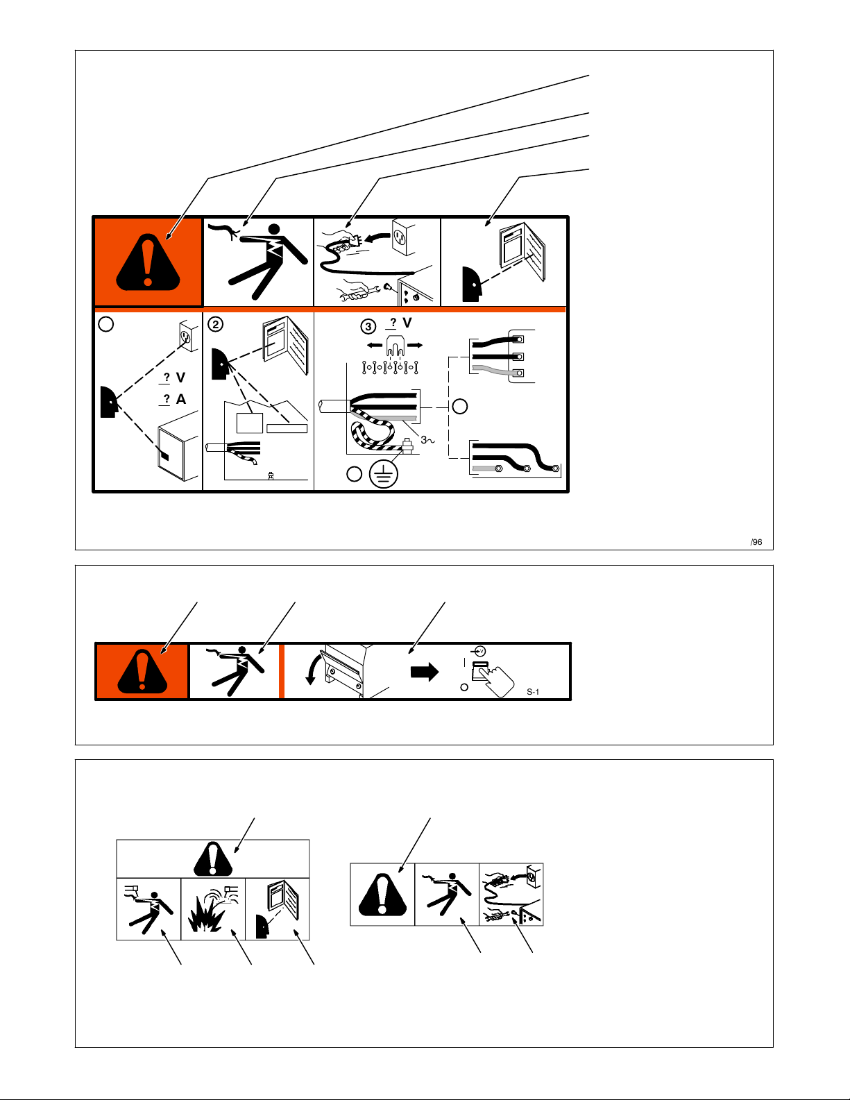
Warning! Watch Out! There are
possible hazards as shown by the
symbols.
Electric shock from wiring can kill.
Disconnect input plug or power
before working on machine.
Read the Owner’s Manual before
working on this machine.
1 Consult rating label for input
power requirements, and
check power available at the
job site − they must match.
2 Read Owner’s Manual and
inside labels for connection
points and procedures.
3 Move jumper links as shown
on inside label to match
?
1
2
V
3
voltage at job site.
4 Having a loop of extra length,
connect grounding conductor
first.
?
V
?
A
5
5 Connect line input conductors
as shown on inside label −
double-check all connections,
jumper link positions, and
input voltage before applying
3
power.
4
12 3
1
1
56
234
S-179 290
1/96
1 Warning! Watch Out! There
are possible hazards as
shown by the symbols.
2 Electric shock from wiring and
exposed weld terminals can
kill.
3 Close door before turning on
unit.
S-179 563
1/96
1 Warning! Watch Out! There
are possible hazards as
shown by the symbols.
2 Electric shock from welding
electrode or wiring can kill.
3 Sparks from arcing electrode
can cause explosion or fire −
disconnect cable for process
not in use.
4 Read Owner’s Manual for
connection procedures.
5 Electric shock from wiring can
kill.
6 Disconnect input power
before working on unit or
making terminal strip
connections.
OM-223 Page 10
Nameplate D-179 389
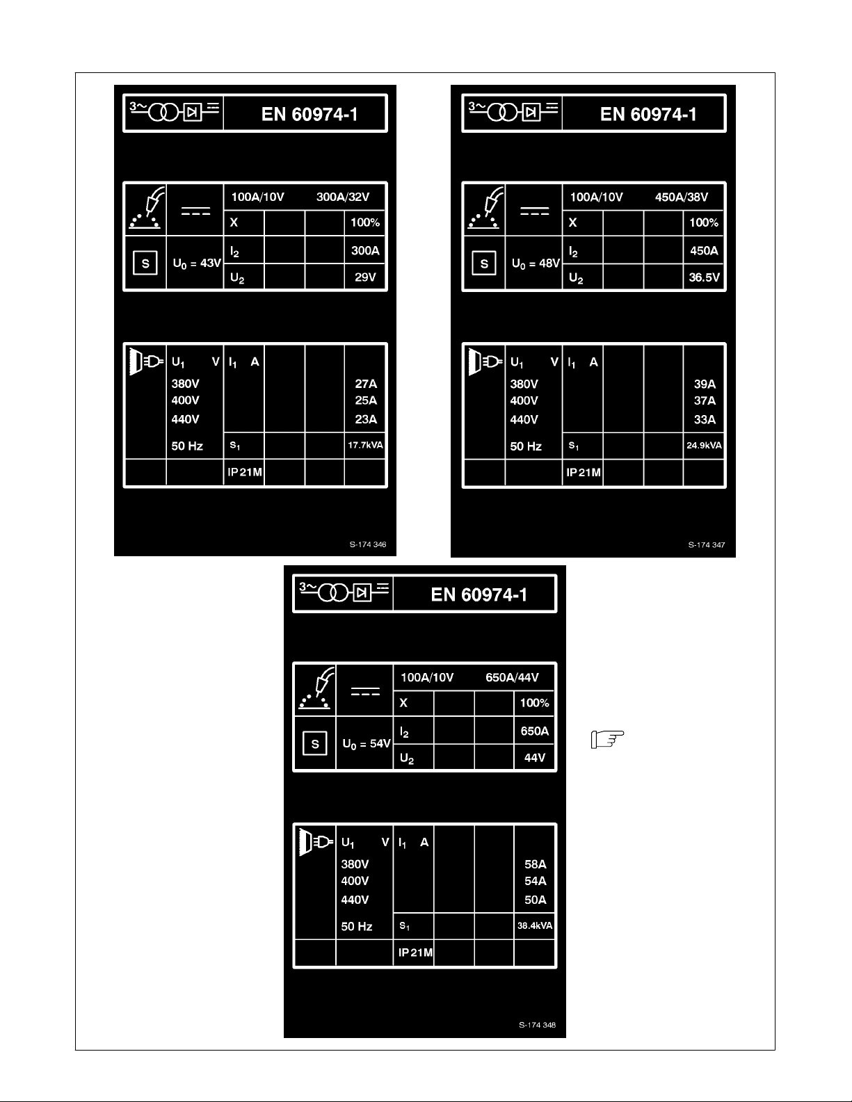
1-2. Manufacturer’s Rating Labels For CE Products
Match label to one on
unit. See Section 2-1.
S-174 346 / S-174 347 / S-174 348
OM-223 Page 11
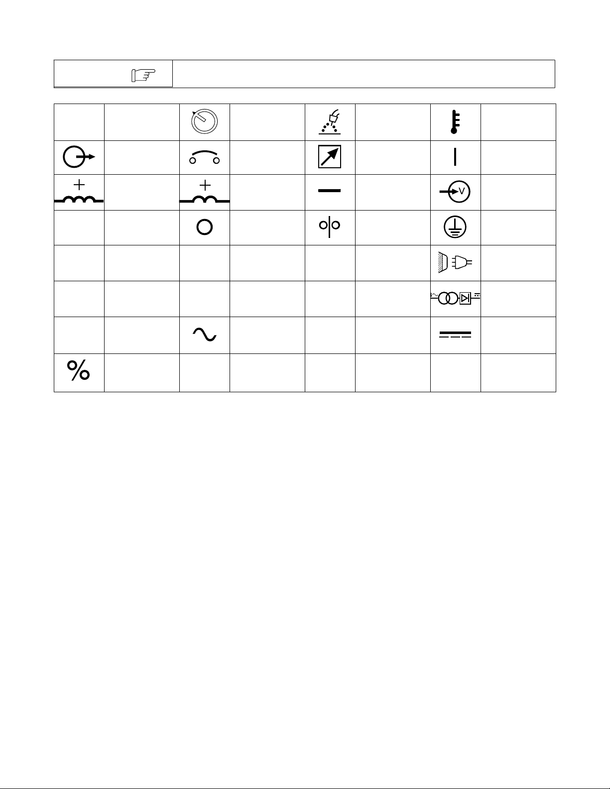
1-3. Symbols And Definitions
NOTE
A
V
U
0
I
1
IP
Some symbols are found only on CE products.
1
Voltage Control/
Panel
Positive Low
Inductance Weld
Output Terminal
Primary Voltage
Rated Welding
Current
Alternating
Current
U
X
S
2
1
Amperes
Output Circuit Breaker Remote On
Positive High
Inductance Weld
Output Terminal
Volts Off Wire Feed
Rated No Load
Voltage (Average)
Primary Current
Degree Of
Protection
U
I
2
Gas Metal Arc
Welding (GMAW)
Negative Weld
Output Terminal
Conventional
Load Voltage
Duty Cycle
KVA Direct Current
Temperature
Input
Protective Earth
(Ground)
Line Connection
Three-Phase
Transformer
Rectifier
Percent
OM-223 Page 12
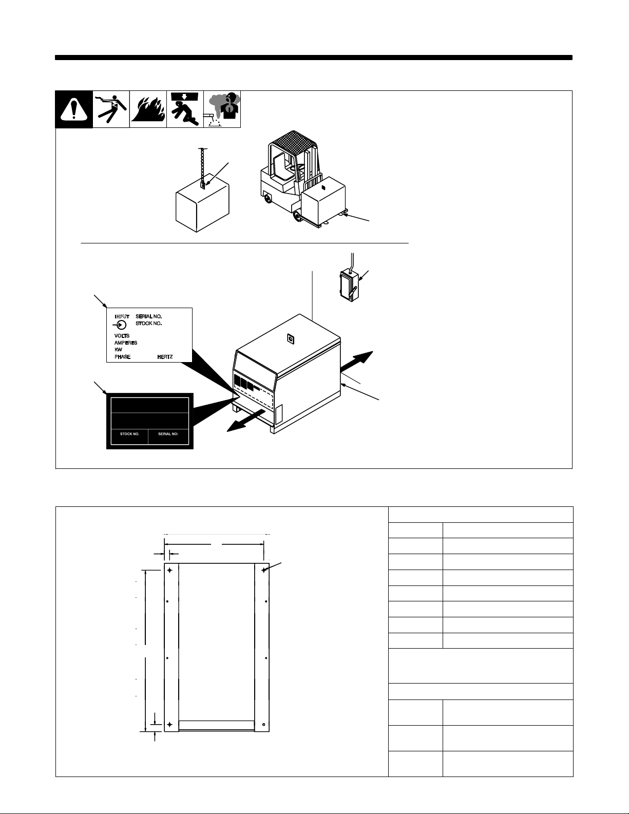
SECTION 2 − INSTALLATION
Di
B
2-1. Selecting A Location
Movement
Location And Airflow
3
4
1 Lifting Eye
2 Lifting Forks
Use lifting eye or lifting forks to
move unit.
If using lifting forks, extend forks
1
OR
2
6
18 in
(460 mm)
beyond opposite side of unit.
3 Rating Label (Non CE Models
Only)
Use rating label to determine input
power needs. Label located under
front access door.
4 Plate Label (CE Models Only)
Label located under front access
door.
5 Rating Label (CE Models
Only)
Use rating label to determine input
power needs. Label located on rear
access door (see Section 1-2).
6 Line Disconnect Device
Locate unit near correct input pow-
er supply.
Y Special installation may be
required where gasoline or
volatile liquids are present −
see NEC Article 511 or CEC
Section 20.
18 in
(460 mm)
2-2. Dimensions And Weights
D
A
C
E
4 Holes
Ref. ST-153 556-A
5
mensions
Height 27-1/4 in (692 mm)
Width 22-1/4 in (565 mm)
Depth* 35-3/4 in (908 mm)
A** 35 in (889 mm)
B*** 1-1/4 in (32 mm)
C 21 in (533 mm)
D 1-3/16 in (30 mm)
E 7/16 in (11 mm) Dia
*300 Amp Model = 28-1/4 in (718 mm)
**300 Amp Model = 25-7/8 in (657 mm)
***300 Amp Model = 3/4 in (19 mm)
Weight
300 Amp
450 Amp
650 Amp
Net: 323 lb (147 kg)
Ship: 340 lb (154 kg)
Net: 384 lb (174 kg)
Ship: 401 lb (182 kg)
Net: 472 lb (214 kg)
Ship: 489 lb (222 kg)
OM-223 Page 13
 Loading...