

Miller COOLMATE 1 W, 300360001, COOLMATE 1 CE, 300459001 Owner's Manual
OWNER’S MANUAL
Coolmate 1
1. Safety Symbol Definitions
OM-235 464G 2011-01
CE And Non-CE Models
NOTICE
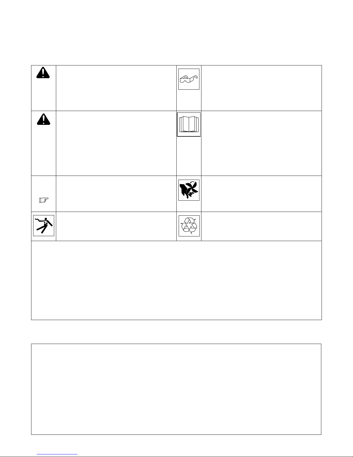
DANGER! − Indicates a hazardous situation which, if not
avoided, will result in death or serious injury. The possible
hazards are shown in the adjoining symbols or explained
in the text.
DANGER! − Indique une situation dangereuse qui si on
l’évite pas peut donner la mort ou des blessures graves.
Les dangers possibles sont montrés par les symboles
joints ou sont expliqués dans le texte.
Indicates a hazardous situation which, if not avoided,
could result in death or serious injury. The possible hazards are shown in the adjoining symbols or explained in
the text.
Indique une situation dangereuse qui si on l’évite pas peut
donner la mort ou des blessures graves. Les dangers possibles sont montrés par les symboles joints ou sont expliqués
dans le texte.
Indicates statements not related to personal injury.
Indique des déclarations pas en relation avec des blessu-
res personnelles.
Indicates special instructions.
Indique des instructions spécifiques.
Beware of electric shock from wiring. Reinstall all panels
and covers.
Risque d’électrocution due au contact avec des fils. Réin-
staller tous les panneaux et couvercles.
Wear safety glasses with side shields.
Porter des lunettes de sécurité avec des protections laté-
rales.
Have only trained and qualified persons install, operate,
or service this unit. Call your distributor if you do not understand the directions. For WELDING SAFETY and
EMF information, read owner’s manual(s).
L’installation, l’exploitation et l’entretien de cet appareil
doivent être confiés uniquement à des personnes qualifiées et convenablement formées. S’adresser à un distributeur si l’on ne comprend pas les directives. Pour les
renseignements ayant trait à la SECURITE lors du soudage et aux champs électromagnétiques, consulter les
manuels traitant les dévidoirs et les sources de courant
pour le soudage.
Beware of moving parts. Keep guards and panels in
place, covers closed, and hands away from moving parts.
Attention aux pièces mobiles. Maintenir les dispositifs de
sécurité et les panneaux en place, les couvercles fermés
et garder les mains éloignées des pièces mobiles.
Recycle or dispose of used coolant in an environmentally
safe way.
Recycler ou éliminer tout liquide de refroidissement usé
conformément aux méthodes prescrites pour assurer la
protection de l’environnement.
CALIFORNIA PROPOSITION 65 WARNINGS
Welding or cutting equipment produces fumes or gases which contain chemicals known to the State of California to cause birth defects
and, in some cases, cancer. (California Health & Safety Code Section 25249.5 et seq.)
This product contains chemicals, including lead, known to the state of California to cause cancer, birth defects, or other reproductive
harm. Wash hands after use.
Avertissements issus de la «Proposition 65»
Les équipements de soudage ou de coupe produisent des émanations ou des gaz qui contiennent des agents chimiques réputés selon
l’État de Californie causer des déficiences congénitales et, dans certains cas, le cancer. (Section 25249.5 et suivantes du «California
Health & Safety Code»)
Ce produit contient des agents chimiques, notamment du plomb, réputés selon l’État de Californie causer des cancers, des malformations congénitales ou d’autres problèmes de procréation. Se laver les mains après utilisation.
2. EMF Information
Electric current flowing through any conductor causes localized electric and magnetic fields (EMF). Welding current creates an EMF field
around the welding circuit and welding equipment. EMF fields may interfere with some medical implants, e.g. pacemakers. Protective
measures for persons wearing medical implants have to be taken. For
example, access restrictions for passers−by or individual risk assessment for welders. All welders should use the following procedures in
order to minimize exposure to EMF fields from the welding circuit:
1. Keep cables close together by twisting or taping them, or using
a cable cover.
2. Do not place your body between welding cables. Arrange
cables to one side and away from the operator.
3. Do not coil or drape cables around your body.
4. Keep head and trunk as far away from the equipment in the
welding circuit as possible.
5. Connect work clamp to workpiece as close to the weld as
possible.
6. Do not work next to, sit or lean on the welding power source.
7. Do not weld whilst carrying the welding power source or wire
feeder.
About Implanted Medical Devices:
Implanted Medical Device wearers should consult their doctor and the
device manufacturer before performing or going near arc welding,
spot welding, gouging, plasma arc cutting, or induction heating operations. If cleared by your doctor, then following the above procedures
is recommended.
2011 MILLER Electric Mfg. Co.
3. Important Information Regarding CE Products (Sold Within The EU)
! This equipment shall not be used by the general public as the EMF limits for the general public might be exceeded during welding.
This equipment is built in accordance with EN 60974−1 and is intended to be used only in an occupational environment (where the general public
access is prohibited or regulated in such a way as to be similar to occupational use) by an expert or an instructed person.
Wire feeders and ancillary equipment (such as torches, liquid cooling systems and arc striking and stabilizing devices) as part of the welding
circuit may not be a major contributor to the EMF. See the Owner’s Manuals for all components of the welding circuit for additional EMF exposure
information.
S The EMF assessment on this equipment was conducted at 0.5 meter.
S At a distance of 1 meter the EMF exposure values were less than 20% of the permissible values.
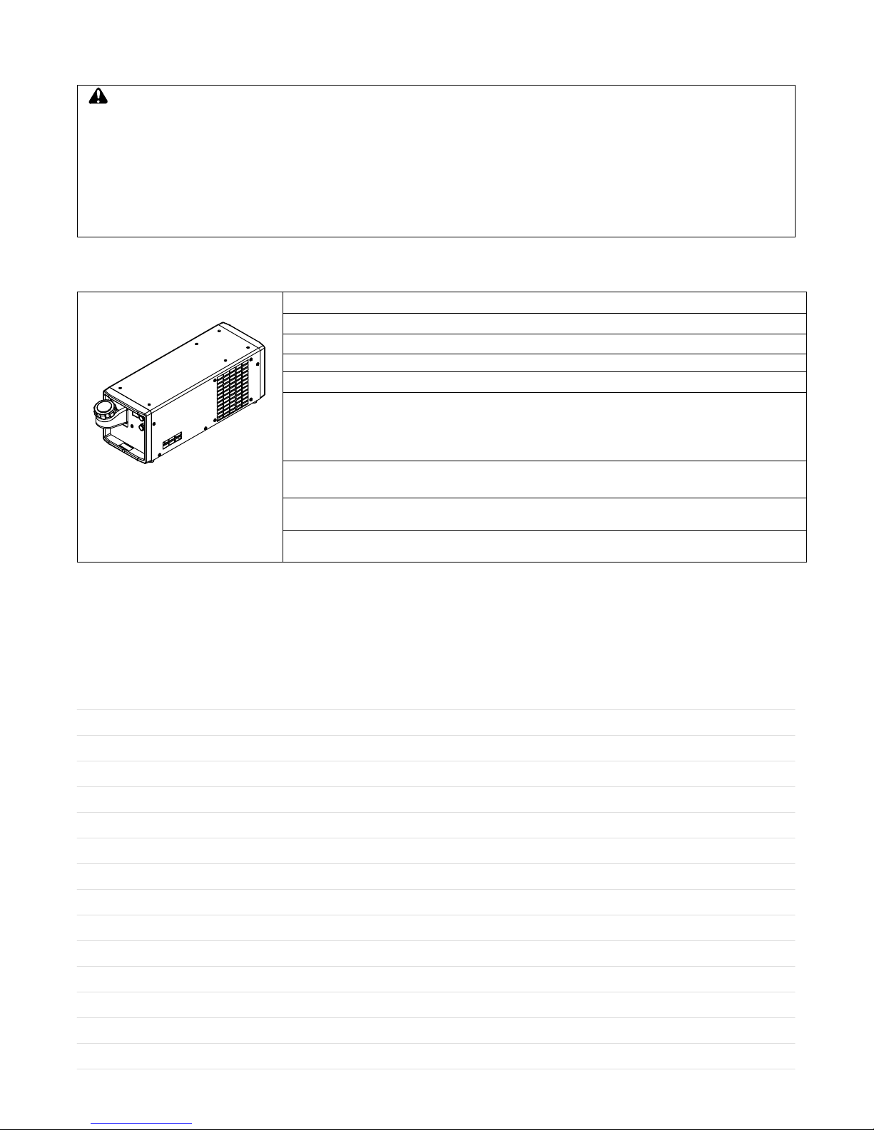
4. Specifications
Recirculating Coolant System For Water-Cooled GTAW Torches And GMAW Guns
Used Primarily With Maxstar 200, Dynasty 200, And Syncrowave 200 Models
IP Rating: 23 − Not Intended For Use In Heavy Rain, Or Near Splashing Water
1 gal (3.8 L) Coolant System Capacity
Max Cooling Capacity: 9700 BTU/hr (2850 Watts) @ 1.7 L/min
IEC Cooling Capacity: 4120 BTU/hr (1210 Watts) @ 1L/min
IEC Cooling Capacity states that the water inlet temperature can not exceed 40 C above ambient temperature at a 1L/min flow rate. Ratings Developed At An Ambient Temperature Of 68 F to 77 F
(20 C To 25 C). Operating Temperature Is 14 F To 104 F (−10 C To 40 C)
Max Welding Amperage Rating: 200 amps @ 40% duty cycle, 175 amps @ 60% duty cycle, 150 amps @
100% duty cycle.
Dimensions: 23-3/4 in. (603 mm) Long, 7-1/2 in. (191 mm) Wide, 8 in. (203 mm) High
805 188-A
Weight: 25 lb (11 kg)
115 Volt Models Use 2.1 Amperes, 60 Hertz, Single-Phase Input Power; 230 Volt Models Use 0.65 Am-
peres, 50/60 Hertz, Single-Phase Input Power
5. Serial Number And Rating Label Location
The serial number and rating information for this product is located on the back panel. Use rating label to determine input power requirements and/or
rated output. For future reference, write serial number in space provided on cover of this manual.
Notes
OM-235 464 Page 2
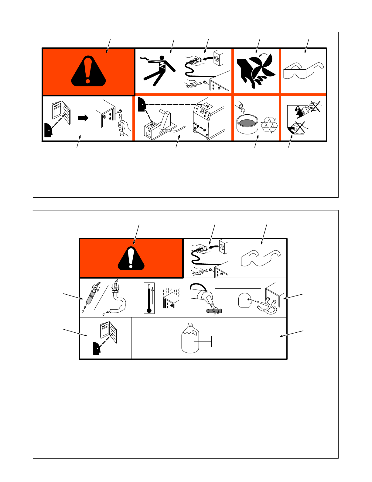
6. Warning Label Definitions For CE Products
1 2 3 4 5
S-180 663
6
1 Warning! Watch Out! There are
possible hazards as shown by the
symbols.
2 Electric shock from wiring can kill.
3 Disconnect input plug or power before
working on machine.
4
5
7 8 9
4 Moving parts, such as fans, can cut
fingers and hands and cause injury.
Keep away from moving parts.
5 Wear safety glasses with side shields.
6 Read the Owner’s Manual before
working on this machine.
7 Read the labels on the welding power
=
source, wire feeder, or other major
equipment for welding safety
information.
8 Recycle or dispose of used coolant in
an environmentally safe way.
9 Do not remove or paint over (cover)
the label.
21 3
100 h. std.
6
7
043 810 (HF)
1 Warning! Watch Out! There are
possible hazards as shown by the
symbols.
2 Disconnect input plug or power before
working on machine.
3 Wear safety glasses with side shields.
4 Plugged filter or hoses cause
043 809 (AL)
overheating and damage.
5 Read Owner’s Manual.
6 Check and clean filter every 100
hours; also check condition of hoses.
7 Use Low Conductivity Coolant No. 043
810 for High-Frequency assisted or
S-178 910
Gas Tungsten Arc Welding
applications. Use Aluminum Protecting
Coolant No. 043 809 where coolant
contacts aluminum parts or for Gas
Metal Arc Welding applications or
where High Frequency is not used.
4/96
OM-235 464 Page 3
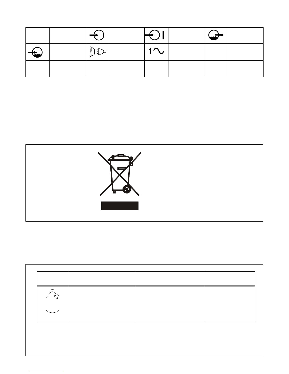
7. Symbols And Definitions
Hz
I
1max
Hertz Input Power Power On Indicator
Water (Coolant) In-
put
Rated Maximum
Supply Current
IP
Line Connection
Degree Of
Protection
P
max
8. WEEE Label (For Products Sold Within The EU)
Single-Phase
Alternating
Current
Rated maximum
power
Water (Coolant)
Output
U
1
Pl/
min
Do not discard product (where applicable) with general waste.
Reuse or recycle Waste Electrical
and Electronic Equipment (WEEE)
by disposing at a designated collection facility.
Contact your local recycling office
or your local distributor for further
information.
Primary Voltage
Power liters per
minute
9. Coolant Chart
Application
Coolant
*HF: High Frequency Current
**Coolants 043 810 and 043 809 protect to -37 F (-38C) and resist algae growth.
NOTICE − Use of any coolant other than those listed in the table voids the warranty on any parts
that come in contact with the coolant (pump, radiator, etc.).
OM-235 464 Page 4
GTAW Or Where
HF* Is Used
Low Conductivity Coolant
No. 043 810**;
Distilled Or Deionized Water
OK Above 32 F (0 C)
GMAW Or Where
HF* Is Not Used
Low Conductivity Coolant
No. 043 810**; Or
Aluminum Protecting Coolant
No. 043 809**;
Distilled Or Deionized Water
OK Above 32 F (0 C)
Where Coolant Contacts
Aluminum Parts
Aluminum Protecting
Coolant No. 043 809**
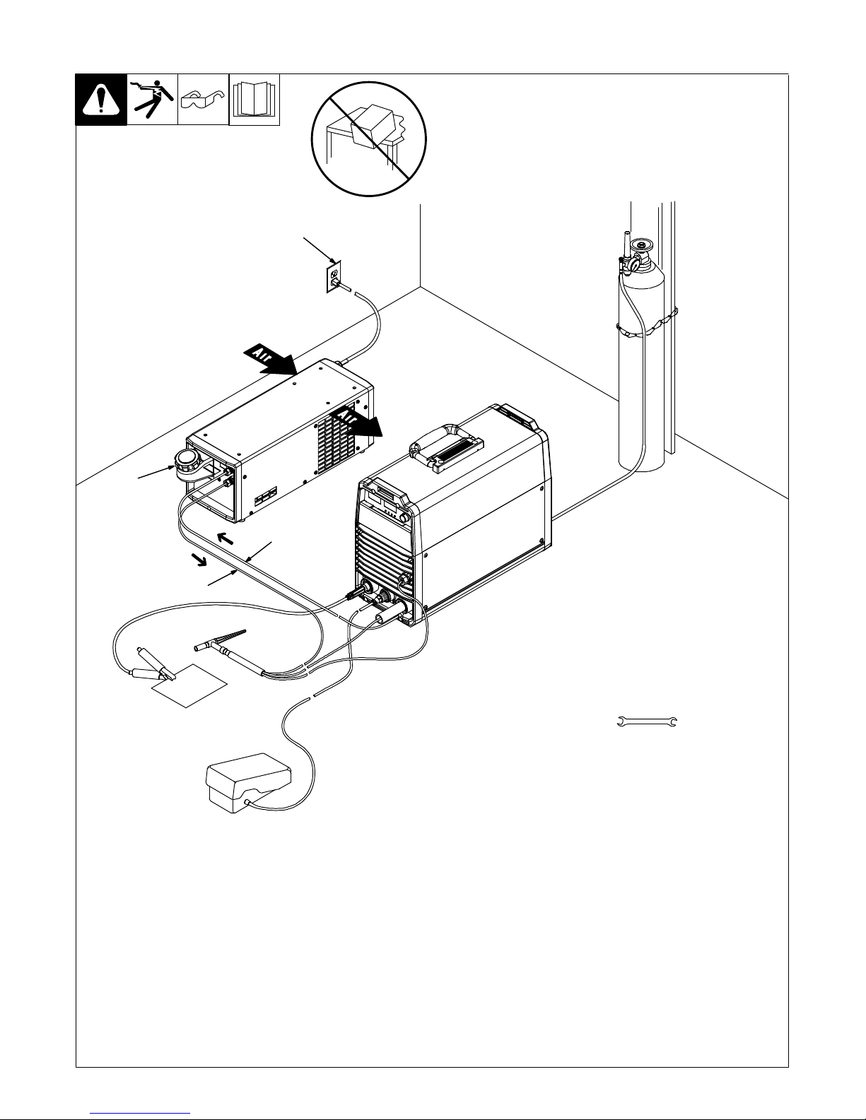
10. GTAW Connections
4
3
2
1
To prevent overheating, make sure cooling
unit is positioned so there is 12 in. (305
mm) of unrestricted airflow on sides of unit.
NOTICE − If welding power source has a
water valve, do not connect hoses to water
valve. Connect hoses as shown.
1 Coolant Out Hose
2 Coolant In Hose
Fittings have 5/8-18 left-hand threads.
Connect hoses with proper fittings as
shown. Some power sources may require
a TIG block.
3 Coolant Tank Cap
4 115 Or 230 Volt AC Grounded Re-
ceptacle (Depending On Model)
NOTICE − Do not cut plug from 115 volt
cord and attempt to rewire for 230 volts, or
do not cut plug from 230 volt cord and attempt to rewire for 115 volts.
For 115 volt models, an individual branch
circuit capable of carrying 15 amperes and
protected by fuses or circuit breakers is
recommended. Recommended fuse or circuit breaker size is 15 amperes. For 230
volt models, an individual branch circuit capable of carrying 10 amperes and protected by fuses or circuit breakers is recommended. Recommended fuse or circuit
breaker size is 10 amperes.
Tools Needed:
11/16 in.
805 189-B
Operation:
. You may experience pump/priming
noise during initial start-up, or after
changing or replacing coolant.
Fill tank with proper coolant. Use table in
Section 9 to select proper coolant. Maintain
coolant level at approximately 1 in (25 mm)
below top of filler neck. Connect hoses as
shown. Unit turns on when plugged in and
power switch is turned on.
. For correct water cooled torch ad-
apters, see Parts List or the Coolmate
Series Options And Accessories
page.
OM-235 464 Page 5
 Loading...