

Miller BOBCAT 225 NT Owner's Manual
Processes
Stick (SMAW) Welding
MIG (GMAW) Welding
Non-Critical TIG (GTAW)
Welding
Descriptio n
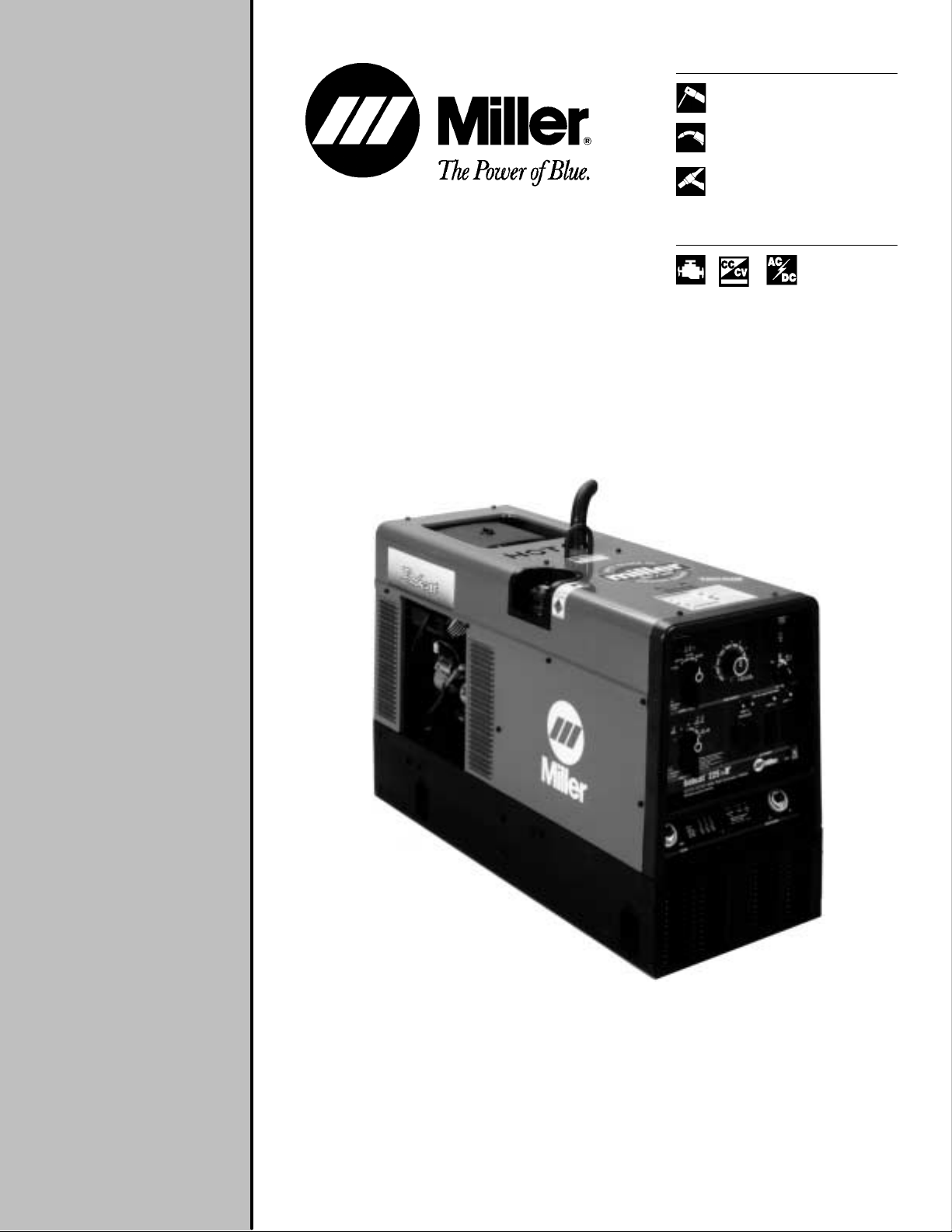
Engine Driven Welding Generator
Bobcat 225 NT
Bobcat 225 NT
OM-405
February 1997
Effective with
Serial Number
KH329624
From Miller to You
Thank you and congratulations on choosing Miller. Now
you can get the job done and get it done right. We know
you don’t have time to do it any other way.
That’s why when Neils Miller first started building arc
welders in 1929, he made sure his products offered
long-lasting value and superior quality. Like you, his
customers couldn’t afford anything less. Miller products
had to be more than the best they could be. They had to
be the best you could buy.
Today, the people that build and sell Miller products continue the
tradition. They’re just as committed to providing equipment and service
that meets the high standards of quality and value established in 1929.
This Owner’s Manual is designed to help you get the most out of your
Miller products. Please take time to read the Safety precautions. They will
help you protect yourself against potential hazards on the worksite. We’ve
made installation and operation quick and easy.
With Miller you can count on years of reliable
service with proper maintenance. And if for
some reason the unit needs repair, there’s a
Troubleshooting section that will help you
Miller is the first
welding equipment
manufacturer in the
U.S.A. to be registered to the ISO 9001
Quality S ystem S tandard.
figure out what the problem is. The parts list
will then help you to decide which exact part
you may need to fix the problem. Warranty and
service information for your particular model
are also provided.
Miller Electric manufactures a full line
of welders and welding related equipment.
For information on other quality Miller
products, contact your local Miller distributor
to receive the latest full line catalog or
individual catalog sheets. To locate your nearest
distributor call 1-800-4-A-Miller.
Working as hard a s you
do – ev ery po wer s ource
from Miller is backed
by the most hassle-free
warranty in the business.

WARNING
The engine exhaust from
this product contains
chemicals known to the
State of California to
cause cancer, birth
defects, or other
reproductive harm.
Call
1-800-4-AMILLER
for your local
Miller distributor.
Bobcat 225 NT
Bobcat 225 NT
Description
Standard engine hour meter. Helps maintain
scheduled preventative maintenance.
The Bobcat 225 NT begins a new tradition in
portable engine-driven welding generators. The
new tradition (NT) design includes all the proven
capabilities of the famous Bobcat 225 Plus
combined with innovative features that meet the
multi-purpose needs of contractors at the job sites.
Features
New full case, rugged housing. Protects engine
and internal components from potential
damage. 60% more sheet metal built into this
durable design compared to the previous
model.
Enlarged, 10 gallon fuel tank and new fuel
gauge. 18% more capacity than the previous
Bobcat series. Larger capacity means more
running time before refueling. Standard fuel
gauge is accurate and easy to read.
Top fuel/oil fill. Fuel fill located on top of unit
allows for easier, more convenient refueling,
plus an overflow cavity directs any spillage
away from the unit. Oil dipstick and fill cap are
easily accessed on top of unit. Fastex oil drain
does not require tools.
New “smart” fuel tank design. Patent-pending
design of the reservoir minimizes the chance of
fuel backflow.
Rotatable exhaust pipe. Adjust exhaust pipe in
any direction – 360 degree rotation possible.
The new muffler design provides quieter ,
improved sound quality.
8000 watts of AC auxiliary power. Dual
purpose welder and power generator provides
needed power at job sites. Auxiliary power
receptacle supplies up to 35 amps of 120 or
240 volts ac to a single load. (Optional GFCI
kits available.)
Two-pole alternator design. Produces
dependable single-phase welding arc.
CV setting with fine adjustment. Premium
performance control when MIG (60/10) and
Flux Cored wire welding. Use CV-DC weld
output for MIG and flux cored wires.
Three overlapping amperage ranges in CC
mode, with fine adjustment. Provides precise
arc control when Stick welding.
225 amps of AC weld output and versatile
AC/DC output for Stick. Multi-process
capability handles a variety of welding jobs.
AC/DC output perfect for most common Stick
electrode types and sizes.
Process selector switch. Quick, simple
change from one weld process to another, AC
to DC straight or DC reverse polarity.
Two engine choices. Customize the new
Bobcat NT with your choice of two gasoline
engines: Onan 16 HP or Kohler 18 HP.
Miller’s True Blue Warranty. New for 1997!
We’ve extended our warranty on welding
generators to 3 years – parts and labor.
Engine is warranted separately by the engine
manufacturer.
Processes
Stick (SMAW) Welding
MIG (GMAW) Welding
Non-Critical TIG (GTAW)
Welding
The following terms are used interchangeably in
this manual: Stick = SMAW, TIG = GTA W,
MIG = GMAW or Wire
Table of Contents
Section Page
Y our distributor gives
you ...
Service
Y ou always get the fast,
reliable response you
need. Most replacement
parts can be in your
hands in 24 hours.
Support
Need fast answers to the
tough welding questions?
Contact your distributor.
The expertise of the
distributor and Miller is
there to help you, every
step of the way.
1. Safety Precautions – Read Before Using 1.
2. Definitions 9. . . . . . . . . . . . . . . . . . . . . . . . . . . .
3. Specifications 9. . . . . . . . . . . . . . . . . . . . . . . . .
4. Installation 13. . . . . . . . . . . . . . . . . . . . . . . . . . . .
5. Operating Welding Generator 16. . . . . . . . . . .
6. Operating Auxiliary Equipment 17. . . . . . . . .
7. Maintenance (Onan-Powered Units) 20. . . . .
8. Maintenance (Kohler-Powered Units) 26. . . .
9. Troubleshooting 31. . . . . . . . . . . . . . . . . . . . . . .
10. Electrical Diagrams 33. . . . . . . . . . . . . . . . . . .
11. Auxiliary Power Guidelines 35. . . . . . . . . . . .
12. Stick Welding (SMAW) Guidelines 42. . . . . .
13. MIG Welding (GMAW) Guidelines 50. . . . . .
14. Parts List 60. . . . . . . . . . . . . . . . . . . . . . . . . . . . .
Options and Accessories
Warranty
Miller offers a Technical Manual
which provides more detailed
service and parts information for
your unit. T o obtain a Technical
Manual, contact your local
distributor. Your distributor can also
supply you with Welding Process
Manuals such as SMAW, GTAW,
GMAW, and GMA W-P.

1 . Safety Precautions – R ead B ef ore U sing
1.1 Symbol Usage
OM-405 - 12/96, safety_rom 12/96
Means Warning! Watch Out! There are possible hazards
with this procedure! The possible hazards are shown in
the adjoining symbols.
Marks a special safety message.
Means “Note”; not safety related.
1.2 Arc Welding Hazards
The symbols shown below are used throughout this manual to
call attention to and identify possible hazards. When you see
the symbol, watch out, and follow the related instructions to
avoid the hazard. The safety information given below is only
a summary of the more complete safety information found in
the Safety Standards listed in Section 1.5. Read and follow all
Safety Standards.
Only qualified persons should install, operate, maintain, and
repair this unit.
During operation, keep everybody, especially children, away.
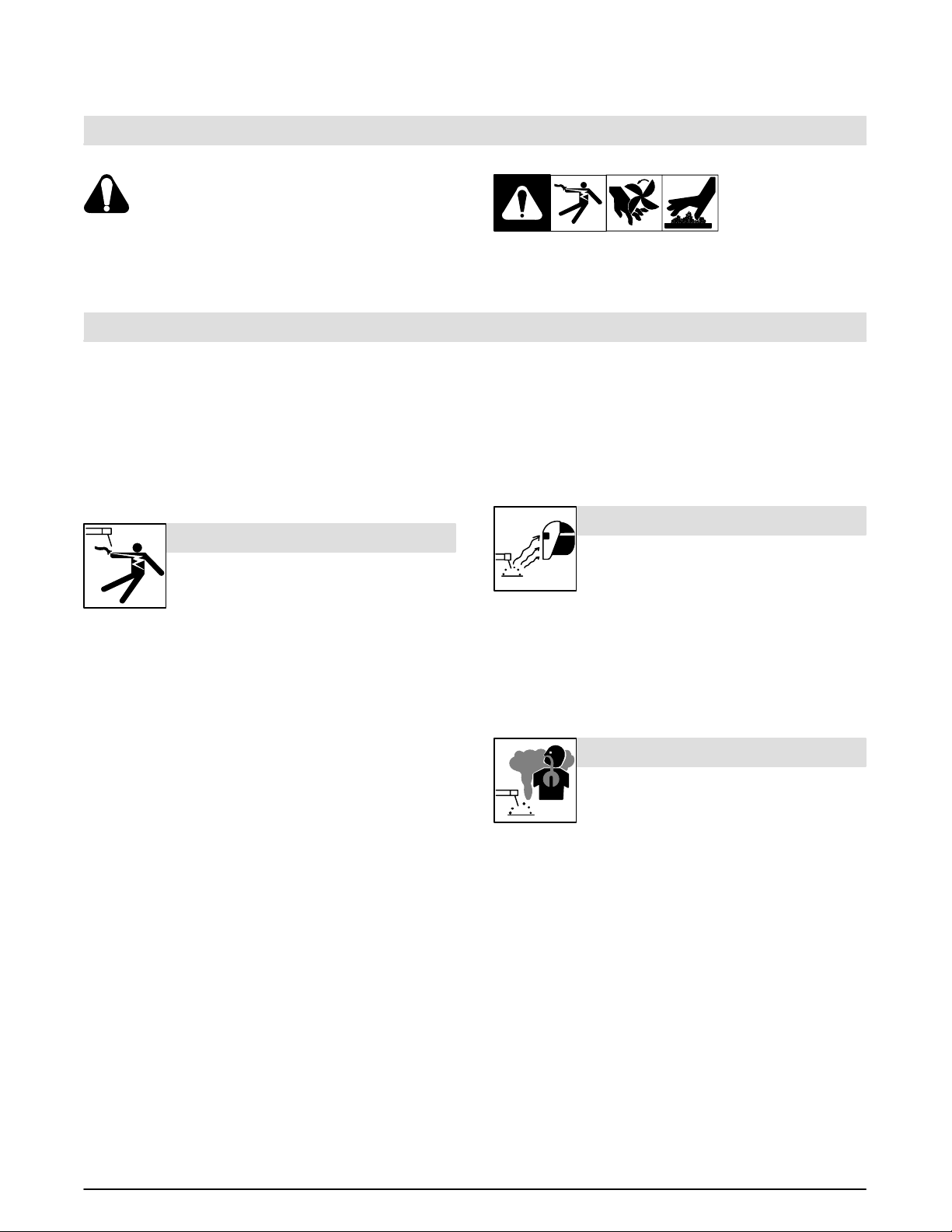
ELECTRIC SHOCK can kill.
Touching live electrical parts can cause fatal shocks
or severe burns. The electrode and work circuit is
electrically live whenever the output is on. The input
live when power is on. In semiautomatic or automatic wire welding, the
wire, wire reel, drive roll housing, and all metal parts touching the
welding wire are electrically live. Incorrectly installed or improperly
grounded equipment is a hazard.
Do not touch live electrical parts.
Wear dry, hole-free insulating gloves and body protection.
Insulate yourself from work and ground using dry insulating mats
or covers big enough to prevent any physical contact with the work
or ground.
Disconnect input power or stop engine before installing or
servicing this equipment. Lockout/tagout input power according to
OSHA 29 CFR 1910.147 (see Safety Standards).
Properly install and ground this equipment according to its
Owner’s Manual and national, state, and local codes.
Always verify the supply ground – check and be sure that input
power cord ground wire is properly connected to ground terminal in
disconnect box or that cord plug is connected to a properly
grounded receptacle outlet.
When making input connections, attach proper grounding conduc-
tor first – double-check connections.
Frequently inspect input power cord for damage or bare wiring –
replace cord immediately if damaged – bare wiring can kill.
Turn off all equipment when not in use.
Do not use worn, damaged, undersized, or poorly spliced cables.
Do not drape cables over your body.
If earth grounding of the workpiece is required, ground it directly
with a separate cable – do not use work clamp or work cable.
Do not touch electrode if you are in contact with the work, ground,
or another electrode from a different machine.
Use only well-maintained equipment. Repair or replace damaged
parts at once. Maintain unit according to manual.
Wear a safety harness if working above floor level.
power circuit and machine internal circuits are also
This group of symbols means Warning! Watch Out! possible
ELECTRIC SHOCK, MOVING PARTS, and HOT PARTS hazards.
Consult symbols and related instructions below for necessary actions
to avoid the hazards.
Keep all panels and covers securely in place.
Clamp work cable with good metal-to-metal contact to workpiece
or worktable as near the weld as practical.
SIGNIFICANT DC VOLTAGE exists after removal of
input power on inverters.
Turn Off inverter, disconnect input power, and discharge input
capacitors according to instructions in Maintenance Section
before touching any parts.
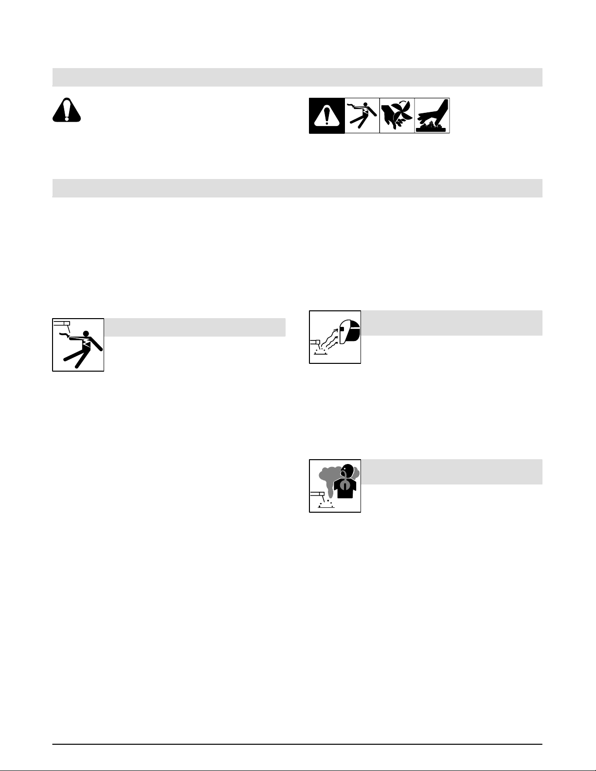
ARC RAYS can burn eyes and skin.
Arc rays from the welding process produce intense
visible and invisible (ultraviolet and infrared) rays
that can burn eyes and skin. Noise from some
processes can damage hearing.
Wear a welding helmet fitted with a proper shade of filter to protect
your face and eyes when welding or watching (see ANSI Z49.1 and
Z87.1 listed in Safety Standards).
Wear approved safety glasses with side shields.
Use protective screens or barriers to protect others from flash and
glare; warn others not to watch the arc.
Wear protective clothing made from durable, flame-resistant mate-
rial (wool and leather) and foot protection.
FUMES AND GASES can be hazardous.
Welding produces fumes and gases. Breathing
these fumes and gases can be hazardous to your
health.
Keep your head out of the fumes. Do not breathe the fumes.
If inside, ventilate the area and/or use exhaust at the arc to remove
welding fumes and gases.
If ventilation is poor, use an approved air-supplied respirator.
Read the Material Safety Data Sheets (MSDSs) and the
manufacturer’s instructions for metals, consumables, coatings,
cleaners, and degreasers.
Work in a confined space only if it is well ventilated, or while
wearing an air-supplied respirator. Always have a trained watchperson nearby. Welding fumes and gases can displace air and
lower th e oxygen level causing injury or death. Be sure the breathing air is safe.
Do not weld in locations near degreasing, cleaning, or spraying op-
erations. The heat and rays of the arc can react with vapors to form
highly toxic and irritating gases.
Do not weld on coated metals, such as galvanized, lead, or
cadmium plated steel, unless the coating is removed from the weld
area, the area is well ventilated, and if necessary, while wearing an
air-supplied respirator. The coatings and any metals containing
these elements can give off toxic fumes if welded.
1OM-405
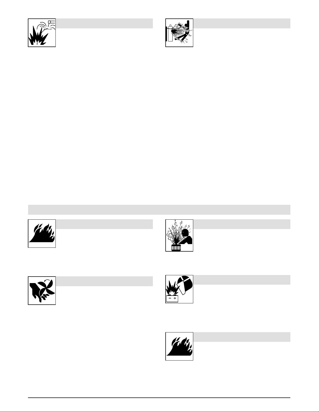
WELDING can cause fire or explosion.
Welding on closed containers, such as tanks,
drums, or pipes, can cause them to blow up. Sparks
can fly off from the welding arc. The flying sparks, hot
burns. Accidental contact of electrode to metal objects can cause
sparks, explosion, overheating, or fire. Check and be sure the area is
safe before doing any welding.
Protect yourself and others from flying sparks and hot metal.
Do not weld where flying sparks can strike flammable material.
Remove all flammables within 35 ft (10.7 m) of the welding arc. If
this is not possible, tightly cover them with approved covers.
Be alert that welding sparks and hot materials from welding can
easily go through small cracks and openings to adjacent areas.
Watch for fire, and keep a fire extinguisher nearby.
Be aware that welding on a ceiling, floor, bulkhead, or partition can
cause fire on the hidden side.
Do not weld on closed containers such as tanks, drums, or pipes,
unless they are properly prepared according to AWS F4.1 (see
Safety Standards).
Connect work cable to the work as close to the welding area as
practical to prevent welding current from traveling long, possibly
unknown paths and causing electric shock and fire hazards.
Do not use welder to thaw frozen pipes.
Remove stick electrode from holder or cut off welding wire at
contact tip when not in use.
Wear oil-free protective garments such as leather gloves, heavy
shirt, cuffless trousers, high shoes, and a cap.
Remove any combustibles, such as a butane lighter or matches,
from your person before doing any welding.
workpiece, and hot equipment can cause fires and
CYLINDERS can explode if damaged.
Shielding gas cylinders contain gas under high
pressure. If damaged, a cylinder can explode. Since
gas cylinders are normally part of the welding
process, be sure to treat them carefully.
Protect compressed gas cylinders from excessive heat, mechani-
cal shocks, slag, open flames, sparks, and arcs.
Install cylinders in an upright position by securing to a stationary
support or cylinder rack to prevent falling or tipping.
Keep cylinders away from any welding or other electrical circuits.
Never drape a welding torch over a gas cylinder.
Never allow a welding electrode to touch any cylinder.
Never weld on a pressurized cylinder – explosion will result.
Use only correct shielding gas cylinders, regulators, hoses, and fit-
tings designed for the specific application; maintain them and
associated parts in good condition.
Turn face away from valve outlet when opening cylinder valve.
Keep protective cap in place over valve except when cylinder is in
use or connected for use.
Read and follow instructions on compressed gas cylinders,
associated equipment, and CGA publication P-1 listed in Safety
Standards.
1.3 Engine Hazards
FUEL can cause fire or explosion.
Stop engine and let it cool of f before checking or
adding fuel.
Do not add fuel while smoking or if unit is near
any sparks or open flames.
Do not overfill tank – allow room for fuel to expand.
Do not spill fuel. If fuel is spilled, clean up before starting engine.
Dispose of rags in a fireproof container.
MOVING PARTS can cause injury.
Keep away from fans, belts, and rotors.
Keep all doors, panels, covers, and guards
closed and securely in place.
Stop engine before installing or connecting unit.
Have only qualified people remove guards or covers for maint-
enance and troubleshooting as necessary.
To prevent accidental starting during servicing, disconnect
negative ( –) battery cable from battery.
Keep hands, hair , loose clothing, and tools away from moving parts.
Reinstall panels or guards and close doors when servicing is
finished and before starting engine.
Before working on generator, remove spark plugs or injectors to
keep engine from kicking back or starting.
Block flywheel so that it will not turn while working on generator
components.
STEAM AND HOT COOLANT can burn.
If possible, check coolant level when engine is
cold to avoid scalding.
If the engine is warm and checking is needed,
follow the next two statements.
Wear safety glasses and gloves and put a rag over radiator cap.
Turn cap slightly and let pressure escape slowly before
completely removing cap.
BATTERY EXPLOSION can BLIND.
Always wear a face shield, rubber gloves, and
protective clothing when working on a battery.
Stop engine before disconnecting or connect-
ing battery cables or servicing battery.
Do not allow tools to cause sparks when working on a battery.
Do not use welder to charge batteries or jump start vehicles.
Observe correct polarity (+ and –) on batteries.
ENGINE HEAT can cause fire.
Do not locate unit on, over, or near combustible
surfaces or flammables.
Keep exhaust and exhaust pipes way from
flammables.
2 OM-405
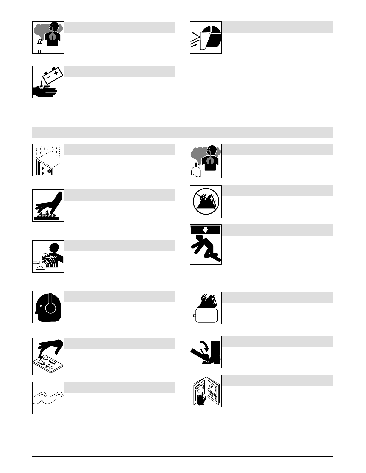
ENGINE EXHAUST GASES can kill.
FL YING M E TAL or SLAG can injure eyes.
Use equipment outside in open, well-ventilated
areas.
If used in a closed area, vent engine exhaust
outside and away from any building air intakes.
Chipping and grinding cause flying metal. As welds
cool, they can throw off pieces of metal or slag.
Wear a face shield to protect eyes and skin.
BATTERY ACID can BURN SKIN and
EYES.
Do not tip battery.
Replace damaged battery.
Flush eyes and skin immediately with water.
1.4 Additional Installation, Operation, and Maintenance Hazards
OVERUSE can cause OVERHEATING
Allow cooling period; follow rated duty cycle.
Reduce current or reduce duty cycle before
starting to weld again.
Do not block or filter airflow to unit.
HOT PARTS can cause severe burns.
Allow cooling period before maintaining.
Wear protective gloves and clothing when
working on a hot engine.
Do not touch hot engine parts or just-welded
parts bare-handed.
BUILDUP OF GAS can injure or kill.
Shut off shielding gas supply when not in use.
EXHAUST SPARKS can cause fire.
Do not let engine exhaust sparks cause fire.
Use approved engine exhaust spark arrestor in
required areas – see applicable codes.
FALLING UNIT can cause injury.
MAGNETIC FIELDS can affect pacemakers.
Pacemaker wearers keep away.
Wearers should consult their doctor before
going near arc welding, gouging, or spot
welding operations.
NOISE can damage hearing.
Noise from some processes or equipment can
damage hearing.
Wear approved ear protection if noise level is
high.
STATIC (ESD) can damage PC boards.
Put on grounded wrist strap BEFORE handling
boards or parts.
Use proper static-proof bags and boxes to
store, move, or ship PC boards.
FLYING METAL or DIRT can injure eyes.
Wear approved safety glasses with side
shields or wear face shield.
Use lifting eye to lift unit only, NOT running
gear, gas cylinders, trailer, or any other
accessories.
Use equipment of adequate capacity to lift and
support unit.
If using lift forks to move unit, be sure forks are
long enough to extend beyond opposite side of
unit.
OVERHEATING can damage motors.
Turn off or unplug equipment before starting or
stopping engine.
Do not let low voltage and frequency caused by
low engine speed damage electric motors.
TILTING OF TRAILER can cause injury.
Use tongue jack or blocks to support weight.
Properly install welding generator onto trailer
according to instructions supplied with trailer.
READ INSTRUCTIONS.
Use only genuine MILLER replacement parts.
Perform engine maintenance and service
according to this manual and the engine
manual.
3OM-405

1.5 Principal Safety Standards
Safety in Welding and Cutting, ANSI Standard Z49.1, from American
Welding Society, 550 N.W. LeJeune Rd, Miami FL 33126
Safety and Health Standards, OSHA 29 CFR 1910, from Superintendent of Documents, U.S. Government Printing Office, Washington, D.C.
20402.
Recommended Safe Practices for the Preparation for Welding and Cutting of Containers That Have Held Hazardous Substances, American
Welding Society Standard AWS F4.1, from American Welding Society,
550 N.W. LeJeune Rd, Miami, FL 33126
National Electrical Code, NFP A Standard 70, from National Fire Protection Association, Batterymarch Park, Quincy, MA 02269.
1.6 EMF Information
Considerations About Welding And The Effects Of Low Frequency
Electric And Ma g netic Fields
The following is a quotation from the General Conclusions Section of the
U.S. Congress, Office of Technology Assessment, Biological Effects of
Power Frequency Electric & Magnetic Fields – Background Paper,
OTA-BP-E-53 (Washington, DC: U.S. Government Printing Of fice, M a y
1989): “. . . there is now a very large volume of scientific findings based
on experiments at the cellular level and from studies with animals and
people which clearly establish that low frequency magnetic fields can
interact with, and produce changes in, biological systems. While most
of this work is of very high quality, the results are complex. Current
scientific understanding does not yet allow us to interpret the evidence
in a single coherent framework. Even more frustrating, it does not yet
allow us to draw definite conclusions about questions of possible risk
or to of fer clear science-based advice on strategies to minimize or avoid
potential risks.”
Safe Handling of Compressed Gases in Cylinders, CGA Pamphlet P-1,
from Compressed Gas Association, 1235 Jefferson Davis Highway,
Suite 501, Arlington, VA 22202.
Code for Safety in Welding and Cutting, CSA Standard W117.2, from
Canadian Standards Association, Standards Sales, 178 Rexdale
Boulevard, Rexdale, Ontario, Canada M9W 1R3.
Safe Practices For Occupation And Educational Eye And Face
Protection, ANSI Standard Z87.1, from American National Standards
Institute, 1430 Broadway, New York, NY 10018.
Cutting And Welding Processes, NFPA Standard 51B, from National
Fire Protection Association, Batterymarch Park, Quincy, MA 02269.
To reduce magnetic fields in the workplace, use the following
procedures:
1. Keep cables close together by twisting or taping them.
2. Arrange cables to one side and away from the operator.
3. Do not coil or drape cables around the body.
4. Keep welding power source and cables as far away from operator as practical.
5. Connect work clamp to workpiece as close to the weld as possible.
About Pacemakers:
The above procedures are also recommended for pacemaker wearers.
Consult your doctor for complete information.
4 OM-405
1 . Consignes de Sécurité – Lire Avant Utilisation
1.1 Signification des symboles
OM-405 – 2/97, safety_rom/fre 12/96
Signifie Mise en garde! Soyez vigilant! Cette procédure
présente des risques de danger! Ceux-ci sont identifiés
par des symboles adjacents aux directives.
Identifie un message de sécurité particulier.
Signifie NOTA; n’est pas relatif à la sécurité.
1.2 Dangers relatifs au soudage à l’arc
Les symboles présentés ci-après sont utilisés tout au long du pré-
sent manuel pour attirer votre attention et identifier les risques de
danger. Lorsque vous voyez un symbole, soyez vigilant et suivez
les directives mentionnées afin d’éviter tout danger. Les consignes de sécurité présentées ci-après ne font que résumer
l’information contenue dans les normes de sécurité énumérées
à la section 1-5. Veuillez lire et respecter toutes ces normes de sécurité.
L’installation, l’utilisation, l’entretien et les réparations ne doi-
vent être confiés qu’à des personnes qualifiées.
Au cours de l’utilisation, tenir toute personne à l’écart et plus par-
ticulièrement les enfants.
UN CHOC ÉLECTRIQUE peut tuer.
Un simple contact avec des pièces électriques peut
provoquer une électrocution ou des blessures graves.
L’électrode et le circuit de soudage sont sous tension
circuits internes de l’appareil sont également sous tension à ce
moment-là. En soudage semi-automatique ou automatique, le fil, le
dévidoir, le logement des galets d’entraînement et les pièces métalliques
en contact avec le fil de soudage sont sous tension. Des matériels mal
installés ou mal mis à la terre présentent un danger.
Ne jamais toucher les pièces électriques sous tension.
Porter des gants et des vêtements de protection secs ne comportant pas
de trous.
S’isoler de la pièce et de la terre au moyen de tapis ou d’autres moyens iso-
lants suffisamment grands pour empêcher le contact physique éventuel
avec la pièce ou la terre.
Couper l ’alimentation ou arrêter le moteur avant de procéder à l’installation,
à la réparation ou à l’entretien de l’appareil. Déverrouiller l’alimentation se-
lon la norme OSHA 29 CFR 1910.147 (voir normes de sécurité).
Installer e t mettre à la terre correctement cet appareil conformément à son
manuel d’utilisation et au codes nationaux, provinciaux et municipaux.
Toujours vérifier la terre du cordon d’alimentation – Vérifier et s’assurer q ue
le fil de terre du cordon d’alimentation est bien raccordé à la borne de terre
du sectionneur ou que la fiche du cordon est raccordée à une prise correctement mise à la terre.
En effectuant les raccordements d’entrée fixer d’abord le conducteur de
mise à la terre approprié et contre-vérifier les connexions.
Vérifier fréquemment le cordon d’alimentation pour voir s’il n’est pas en-
dommagé ou dénudé – remplacer le cordon immédiatement s’il est
endommagé – un câble dénudé peut provoquer une électrocution.
Mettre l’appareil hors tension quand on ne l’utilise pas.
Ne pas utiliser des câbles usés, endommagés, de grosseur insuffisante ou
mal épissés.
Ne pas enrouler les câbles autour du corps.
Si la pièce soudée doit être mise à la terre, le faire directement avec un câ-
ble distinct – ne pas utiliser le connecteur de pièce ou le câble de retour.
Ne pas toucher l’électrode quand on est en contact avec la pièce, la terre ou
une électrode provenant d’une autre machine.
N’utiliser qu’un matériel en bon état. Réparer ou remplacer sur-le-champ
les pièces endommagées. Entretenir l’appareil conformément à ce manuel.
dès que l’appareil est sur ON. Le circuit d’entrée et les
Ce groupe de symboles signifie Mise en garde! Soyez vigilant! Il y a des
risques de danger reliés aux CHOCS ÉLECTRIQUES, aux PIÈCES EN
MOUVEMENT et aux PIÈCES CHAUDES. Reportez-vous aux symboles
et aux directives ci-dessous afin de connaître les mesures à prendre pour
éviter tout danger.
Porter un harnais de sécurité quand on travaille en hauteur.
Maintenir solidement en place tous les panneaux et capots.
Fixer le c âble de retour de façon à obtenir un bon contact métal-métal avec
la pièce à souder ou la table de travail, le plus près possible de la soudure.
Il y a DU COURANT CONTINU IMPORTANT dans les
convertisseurs après la suppression de l’alimenta-
tion électrique.
Arrêter les convertisseurs, débrancher le courant électrique, et décharger
les condensateurs d’alimentation selon les instructions indiquées dans la
partie entretien avant de toucher les pièces.
LE RAYONNEMENT DE L’ARC peut
brûler les yeux et la peau.
L’arc de soudage produit des rayons visibles et
invisibles intenses (ultraviolets et infrarouges) qui
peuvent brûler les yeux et la peau. Le bruit produit p a r
certains procédés peut endommager l’ouïe.
Porter un masque à serre-tête muni d’un verre filtrant de nuance appro-
priée pour protéger le visage et les yeux quand on soude ou observe la
travail de soudage (voir les normes ANSI Z49.1 et Z87.1 données sous la
rubrique Principales normes de sécurité).
Porter des lunettes de sécurité approuvées avec écrans latéraux.
Utiliser des paravents ou des barrières de protection pour protéger les per-
sonnes à proximité contre les coups d’arc et l’éblouissement; avertir les
autres personnes de ne pas regarder l’arc.
Porter des vêtements de protection en tissu ignifuge durable (laine et cuir)
et des chaussures de sécurité.
LES VAPEURS ET LES FUMÉES peuvent être dangereuses.
Le soudage produit des vapeurs et des fumées qu’il est
dangereux de respirer.
Garder l a t ête à l’extérieur des vapeurs et des fumées et ne pas les respirer.
À l’intérieur, ventiler le poste de travail ou utiliser un dispositif placé au ni-
veau de l’arc pour évacuer les vapeurs et fumées de soudage.
Si la ventilation est mauvaise, utiliser un appareil respiratoire à adduction
d’air pur approuvé.
Consulter les fiches signalétiques et les consignes du fabricant relatives au
métaux, produits d’apport, revêtements, nettoyants et dégraissants.
Ne travailler dans un espace confiné que s’il est bien ventilé, ou en portant
un appareil respiratoire à adduction d’air pur. Demander à un observateur
ayant reçu la bonne formation de toujours se tenir à proximité. Les vapeurs
et fumées de soudage peuvent déplacer l’air et abaisser le niveau d’oxygè-
ne et causer des blessures graves voire mortelles. S’assurer que l’air est
propre à la respiration.
Ne pas souder à proximité d’opérations de dégraissage, de nettoyage ou
de pulvérisation. La chaleur et les rayons de l’arc peuvent réagir avec les
vapeurs pour former des gaz hautement toxiques et irritants.
Ne pas souder sur des métaux revêtus comme l’acier galvanisé, au plomb
ou cadmié à moins que la pièce n’ait été entièrement décapée, que le poste
de travail soit bien ventilé. S’il y a lieu, porter un appareil respiratoire à ad-
5OM-405

duction d’air pur. Les revêtements et les métaux qui contiennent de tels
éléments peuvent dégager des vapeurs toxiques lors du soudage.
LE SOUDAGE peut causer un incendie ou une explosion.
Ne pas souder sur des récipients fermés comme des
réservoirs, des fûts ou des tuyaux : ils peuvent
exploser. L’arc de soudage peut produire des étincel-
chaud peuvent provoquer des incendies et des blessures. Le contact
accidentel de l’électrode sur des objets métalliques peut produire des
étincelles, l’explosion, la surchauffe ou un incendie. S’assurer que le lieu
ne présente pas de danger avant d’effectuer le soudage.
Se protéger et protéger les personnes à proximité des étincelles et du métal
chaud.
Ne pas souder dans un endroit où les étincelles peuvent atteindre des ma-
tériaux inflammables.
Enlever toutes les matières inflammables dans un rayon de moins de 10 m
de l’arc. Si cela n’est pas possible, bien les recouvrir en utilisant des bâches
approuvées.
Prendre garde que les étincelles et les projections ne pénétrant dans des
zones adjacentes en s’infiltrant dans des petites fissures et ouvertures.
Prendre garde aux incendies et toujours avoir un extincteur à proximité.
Se rappeler que si l’on soude sur un plafond, un plancher, une cloison ou
autre, le feu peut prendre de l’autre côté.
Ne pas souder sur des récipients fermés comme des réservoirs, des fûts
ou des tuyaux à moins qu’ils ne soient préparés de façon appropriée
conformément à la norme F4.1 de l’AWS (voir la rubrique Principales normes de sécurité).
Raccorder le c âble de retour à la pièce, le plus près possible de la zone de
soudage, pour empêcher que le courant de soudage ne suive une trajectoire longue et éventuellement inconnue et qu’il ne provoque des risques
d’électrocution et d’incendie.
Ne pas utiliser le chalumeau soudeur pour dégeler des tuyaux.
Enlever l ’électrode enrobée du porte-électrode ou couper le fil de soudage
au ras du bec contact quand on ne l’utilise pas.
Porter des vêtements de protection non huileux comme des gants en cuir,
une chemise épaisse, des pantalons sans revers, des chaussures montantes et un casque.
Ne pas porter des matières combustibles sur soi comme un briquet à gaz
ou des allumettes quand on soude.
les. Des étincelles, une pièce chaude et un matériel
LES BOUTEILLES peuvent exploser
si elles sont endommagées.
Les bouteilles contenant des gaz de protection sont à
haute pression. Une bouteille endommagée peut
exploser. Étant donné que les bouteilles de gaz font
normalement partie du matériel de soudage, les traiter
avec le plus grand soin.
Protéger les bouteilles de gaz comprimé contre la chaleur intense, les
chocs, le laitier, les flammes nues, les étincelles et l’arc.
Placer les bouteilles à la verticale en les fixant à un support fixe ou à un cha-
riot pour éviter qu’elles ne tombent ou ne basculent.
Tenir les bouteilles à l’écart du poste de soudage ou d’autres circuits électri-
ques.
Ne jamais poser un chalumeau soudeur sur une bouteille de gaz.
Ne jamais laisser une électrode de soudage toucher une bouteille.
Ne jamais souder sur une bouteille sous pression : elle exploserait.
N’utiliser que des bouteilles de gaz de protection, des détendeurs, des
tuyaux souples et des raccords appropriés conçus pour l’application particulière; conserver ces matériels et leurs pièces en bon état.
Éloigner le visage de la sortie du robinet de la bouteille quand on l’ouvre.
Replacer le chapeau sur la bouteille après utilisation.
Lire et suivre les consignes relatives aux bouteilles de gaz comprimé, au
matériel connexe ainsi que la publication P-1 de la CGA donnée sous la ru-
brique Principales normes de sécurité.
1.3 Dangers relatifs au moteur
LE CARBURANT peut causer un
incendie ou une explosion.
Arrêter le moteur avant de vérifier le niveau de carbu-
rant ou de faire le plein.
Ne pas faire le plein en fumant ou proche d’une sour-
ce d’étincelles ou d’une flamme nue.
Ne pas faire le plein de carburant à ras bord; prévoir de l’espace pour son
expansion.
Faire attention de ne pas renverser de carburant. Nettoyer tout carbu-
rant renversé avant de faire démarrer le moteur.
Jeter les chiffons dans un récipient ignifuge.
LES PIÈCES EN MOUVEMENT
peuvent causer des blessures.
Ne pas approcher les mains des ventilateurs, cour-
roies et autres pièces en mouvement
S’assurer que les portes, les panneaux, les capots et
les protecteurs sont bien fermés.
Avant d’utiliser ou de connecter un système, arrêter le moteur.
Seules des personnes qualifiées doivent démonter des protecteurs ou
des capots pour faire l’entretien ou le dépannage nécessaire.
Pour e m p êcher un démarrage accidentel d’un système pendant l’entre-
tien, débrancher le câble d’accumulateur à la borne négative.
Ne pas approcher les mains ou les cheveux de pièces en mouvement;
elles peuvent aussi accrocher des vêtements amples et des outils.
Réinstaller les capots ou les protecteurs et fermer les portes après des
travaux d’entretien et avant de faire démarrer le moteur.
Avant d’intervenir , déposez les bougies ou injecteurs pour éviter la mise
en route accidentelle du moteur.
Bloquer le volant moteur pour éviter sa rotation lors d’une intervention
sur le générateur.
6 OM-405

LA VAPEUR ET LE LIQUIDE DE
REFROIDISSEMENT CHAUD peuvent
provoquer des brûlures.
Il est préférable de vérifier le liquide de refroidisse-
ment une fois le moteur refroidi.
Si le moteur est chaud et que le liquide doit être véri-
fié, opérer comme suivant :
Mettre des lunettes de sécurité et des gants, placer un torchon sur le
bouchon du radiateur.
Dévisser le bouchon légèrement et laisser la vapeur s’échapper avant
d’enlever le bouchon.
L’EXPLOSION DE LA BATTERIE peut
RENDRE AVEUGLE.
Toujours porter une protection faciale, des gants en
caoutchouc et vêtements de protection lors d’une in-
tervention sur la batterie.
Arrêter le moteur avant de débrancher ou de bran-
cher les câbles de batterie.
Utiliser uniquement des outils anti-étincelles pour travailler sur un accu-
mulateur.
Ne pas utiliser un poste de soudage pour charger un accumulateur ou
pour faire démarrer un véhicule.
Ne pas intervertir la polarité d’un accumulateur.
LA CHALEUR DU MOTEUR peut
provoquer un incendie.
Ne pas placer l’appareil sur, au-dessus ou à proximité
de surfaces inflammables.
Tenir a distance les produits inflammables de
l’échappement.
7OM-405
LES GAZ D’ÉCHAPPEMENT DES
MOTEURS peuvent être mortels.
DES ÉCLATS DE MÉTAL ou DE
LAITIER peuvent causer des
blessures aux yeux.
Utiliser les machines à l’extérieur dans des aires ou-
vertes et bien ventilées.
Si vous utilisez des machines dans un endroit confi-
né, les fumées d’échappement doivent être envoyées à l’extérieur , loin des prises d’air du bâtiment.
Meuler ou extraire le laitier peuvent provoquer des
particules volantes. Lors du refroidissement des
soudures des éclats de laitier peuvent se dégager.
Porter un écran facial pour protéger le visage et
les yeux.
L’ÉLECTROLYTE peut BRÛLER LA
PEAU ET LES YEUX.
Ne pas basculer un accumulateur.
Remplacer tout accumulateur endommagé.
Laver im m édiatement les yeux et la peau, abondam-
ment avec de l’eau.
1.4 Autres dangers relatifs à l’installation, l’utilisation et l’entretien
UNE SURUTILISATION peut
SURCHAUFFER L’ÉQUIPEMENT.
Laisser l’équipement refroidir.; respecter le facteur de
marche nominal.
Réduire le courant ou le facteur de marche avant de
poursuivre le soudage.
Ne pas obstruer les passages d’air du poste.
LES PIÈCES CHAUDES peuvent
causer des brûlures sévères.
Laisser refroidir avant d’effectuer l’entretien.
Porter des gants et des vêtements de protection lors-
que vous devez toucher à un moteur chaud.
Ne pas toucher a mains nues les parties chaudes du
moteur ni les pièces récemment soudées.
LES CHAMPS MAGNÉTIQUES peuvent affecter les stimulateurs cardiaques.
Les personnes qui portent un stimulateur cardiaque
doivent se tenir éloignées des postes de soudage.
Elles devraient consulter leur médecin avant de s’ap-
procher d’un poste de soudage à l’arc, de gougeage
ou de soudage par points.
LE BRUIT peut affecter l’ouïe
Le bruit des processus et des équipements peut
affecter l’ouïe.
Porter des protections approuves pour les oreilles
si le niveau sondre est trop élevé.
LES CHARGES ÉLECTROSTATI-
QUES peuvent endommager les circuits
imprimés
Porter un bracelet antistatique AVANT de manipuler
une carte ou une pièce.
Utiliser des sacs et des boîtes antistatiques appro-
priés pour ranger, déplacer ou expédier des cartes
PC.
DES PARTICULES VOLANTE
peuvent blesser les yeux.
Porter des lunettes de sécurité avec écrans latéraux
ou un écran facial.
L’ACCUMULATION DE GAZ PROTECTEUR peut être dangereuse pour la
santé ou peut provoquer des
accidents mortels.
Fermer l’alimentation du gaz protecteur en cas de
non utilisation.
LES ËTINCELLES À L’ÉCHAPPE-
MENT peuvent provoquer un incendie.
Empêcher les etincelles d’échappement du moteur
de provoquer un incendie.
Utiliser uniquement un pare-étincelles approuvé –
voir codes en vigueur.
LA CHUTE DE L’APPAREIL peut blesser
Utiliser l ’anneau de levage uniquement pour soulever
l’appareil lui-même; sans chariot, de bouteilles de
gaz, remorque, ou autres accessoires.
Utiliser un équipement de levage de capacité suffi-
sante pour lever l’appareil.
En cas de manipulation avec un chariot élévateur
s’assurer que les bout opposé de l’appareil.
LE SURCHAUFFEMENT peut endommager le moteur électrique
Mettre hors tension ou débrancher l’équipement
avant de démarrer ou d’arrêter le moteur.
Ne pas laisser tourner le moteur trop lentement sous
risque d’endommager le moteur électrique a cause
d’une tension et d’une fréquence trop faible.
8 OM-405

UNE REMORQUE QUI BASCULE peut
entraîner des blessures.
Utiliser les supports de la remorque ou des blocs
pour soutenir le poids.
Installer convenablement le poste sur la remorque
comme indiqué dans le manuel s’y rapportant.
LIRE LES INSTRUCTIONS.
Utiliser uniquement des pièces de rechange
MILLER.
Effecteur la maintenance et la mise en service
d’après le manuel et celui du moteur.
9OM-405

1.5 Principales normes de sécurité
Safety in Welding and Cutting, norme ANSI Z49.1, de l’American Wel-
ding Society, 550 N.W. Lejeune Rd, Miami FL 33126
Safety and Health Sandards, OSHA 29 CFR 1910, du Superintendent
of Documents, U.S. Government Printing Office, Washington, D.C.
20402.
Recommended Safe Practice for the Preparation for Welding and Cutting of Containers That Have Held Hazardous Substances, norme A WS
F4.1, de l ’American Welding Society , 550 N.W. Lejeune Rd, Miami FL
33126
National Electrical Code, NFP A Standard 70, de la National Fire Protection Association, Batterymarch Park, Quincy, MA 02269.
Safe Handling of Compressed Gases in Cylinders, CGA Pamphlet P-1,
de la Compressed Gas Association, 1235 Jefferson Davis Highway,
Suite 501, Arlington, VA 22202.
Règles de s écurité en soudage, coupage et procédés connexes, norme
CSA W117.2, de l’Association canadienne de normalisation, vente de
normes, 178 Rexdale Boulevard, Rexdale (Ontario) Canada M9W 1R3.
Safe Pra ctices For Occupation And Educational Eye And Face Protection, norme ANSI Z87.1, de l’American National Standards Institute,
1430 Broadway, New York, NY 10018.
Cutting and Welding Processes, norme NFPA 51B, de la National Fire
Protection Association, Batterymarch Park, Quincy, MA 02269.
1.6 Information sur les champs électromagnétiques
Données sur le soudage électrique et sur les ef fets, pour l ’organisme,
des champs magnétiques basse fréquence
L’extrait suivant est tiré des conclusions générales du document intitulé
Biological Effects of Power Frequency Electric & Magnetic Fields –
Background Paper, OTA–BP–E–53 (Washington DC : U.S. Government Printing Office, mai 1989), publié par le Office of Technology
Assessment du Congrès américain : «... il existe maintenant d’abondantes données scientifiques compilées à la suite d’expériences sur la
cellule ou d’études sur des animaux et des humains, qui montrent clairement que les champs électromagnétiques basse fréquence peuvent
avoir des effets sur l’organisme et même y produire des transformations. Même s’il s’agit de travaux de très grande qualité, les résultats
sont complexes. Cette démarche scientifique ne nous permet pas
d’établir un tableau d’ensemble cohérent. Pire encore, elle ne nous permet pas de tirer des conclusions finales concernant les risques
éventuels, n i d ’offrir des conseils sur les mesures à prendre pour réduire sinon éliminer les risques éventuels». (Traduction libre)
Afin de réduire les champs électromagnétiques dans l’environnement
de travail, respectez les consignes suivantes :
1 Gardez les câbles ensembles en les torsadant ou en les
attachant avec du ruban adhésif.
2 Mettre tous les câbles du côté opposé de l’opérateur.
3 Ne courbez pas et n’entourez pas les câbles autour de vous.
4 Gardez le poste de soudage et les câbles le plus loin possible de
vous.
5 Reliez la pince de masse le plus près possible de la zone de
soudure.
Consignes relatives aux stimulateurs cardiaques :
Les consignes mentionnées précédemment font partie de celles destinées aux personnes ayant recours à un stimulateur cardiaque. Veuillez
consulter votre médecin pour obtenir plus de détails.
10 OM-405
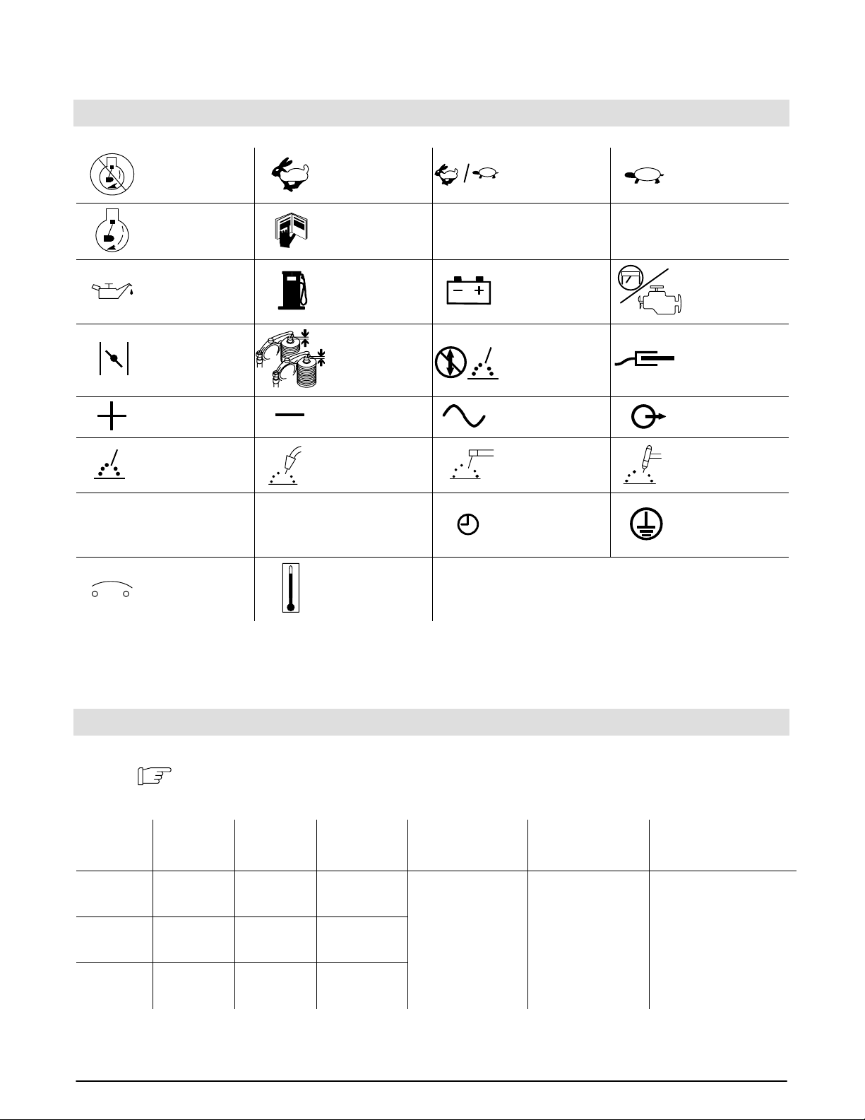
2. Definitions
2.1 Symbol Definitions
h
Stop Engine
Start Engine
Engine Oil Fuel Battery (Engine) Engine
Engine Choke
Positive Negative
Welding Arc
(Electrode)
Hours
Fast
(Run, Weld/Power)
Read Operator’s
Manual A
Check Valve
Clearance
MIG (GMAW),
Wire
Seconds Time
Fast/Slow
(Run/Idle)
Amperes
Do not switch while
welding
Alternating Current
(AC)
Stick (SMAW) TIG (GTAW)
V
Slow (Idle)
Volts
Work Connection
Output
Protective Earth
(Ground)
s
Circuit Breaker Temperature
3. Specifications
3.1 Weld, Power, and Engine Specifications
Note
Welding
Mode
CC/AC 50 – 225 A
CC/DC 50 – 210 A
CV/DC 17 – 28 V
This unit uses either an Onan or a Kohler engine. Differences between models are noted
throughout this manual.
Weld
Output
Range
Rated
Welding
Output
225 A, 25 V ,
100% Duty
Cycle
210 A, 25 V ,
100% Duty
Cycle
200 A, 20 V ,
100% Duty
Cycle
Maximum
OpenCircuit
Voltage
80
72
33
Auxiliary Power
Rating
Single-Phase,
8 kVA/kW, 70/35 A,
120/240 V AC, 60 Hz
Fuel Capacity Engine
Onan Performer P216
Air-Cooled, Two-Cylinder,
Four-Cycle, 16 HP
Four-Cycle, 16 HP
Gasoline Engine
10 gal (38 L) Tank
or
Kohler CH-18
Kohler CH-18
Air-Cooled, Two-Cylinder,
Four-Cycle, 18 HP
Gasoline Engine
11OM-405

3.2 Dimensions, Weights, and Operating Angles
°
Dimensions
Height 33-1/2 in (851 mm)
Width 18-3/4 in (476 mm)
Depth 46 in (1164 mm)
A 18 in (457 mm)
B 16-1/2 in (419 mm)
C 3/4 in (19 mm)
D 3-1/8 in (79 mm)
E 32-3/4 in (832 mm)
F 45-1/2 in (1156 mm)
G 13/32 in (10 mm) Dia.
3.3 Auxiliary Power Curve
The auxiliary power curve shows
the auxiliary power in amperes
available at the receptacles.
A
B
C
D
G
G
4 Holes
E
F
Engine End
ST-800 426
Do not exceed operating angles while run-
ning or engine damage will occur.
ning or engine damage will occur.
Do not move or operate unit where it could
tip.
25°
25°
°
25
25°
Weight
Onan-Powered Unit: 573 lb (260 kg)
Kohler-Powered Unit: 565 lb (256 kg)
Kohler-Powered Unit: 565 lb (256 kg)
25
ST-166 023-A
12 OM-405
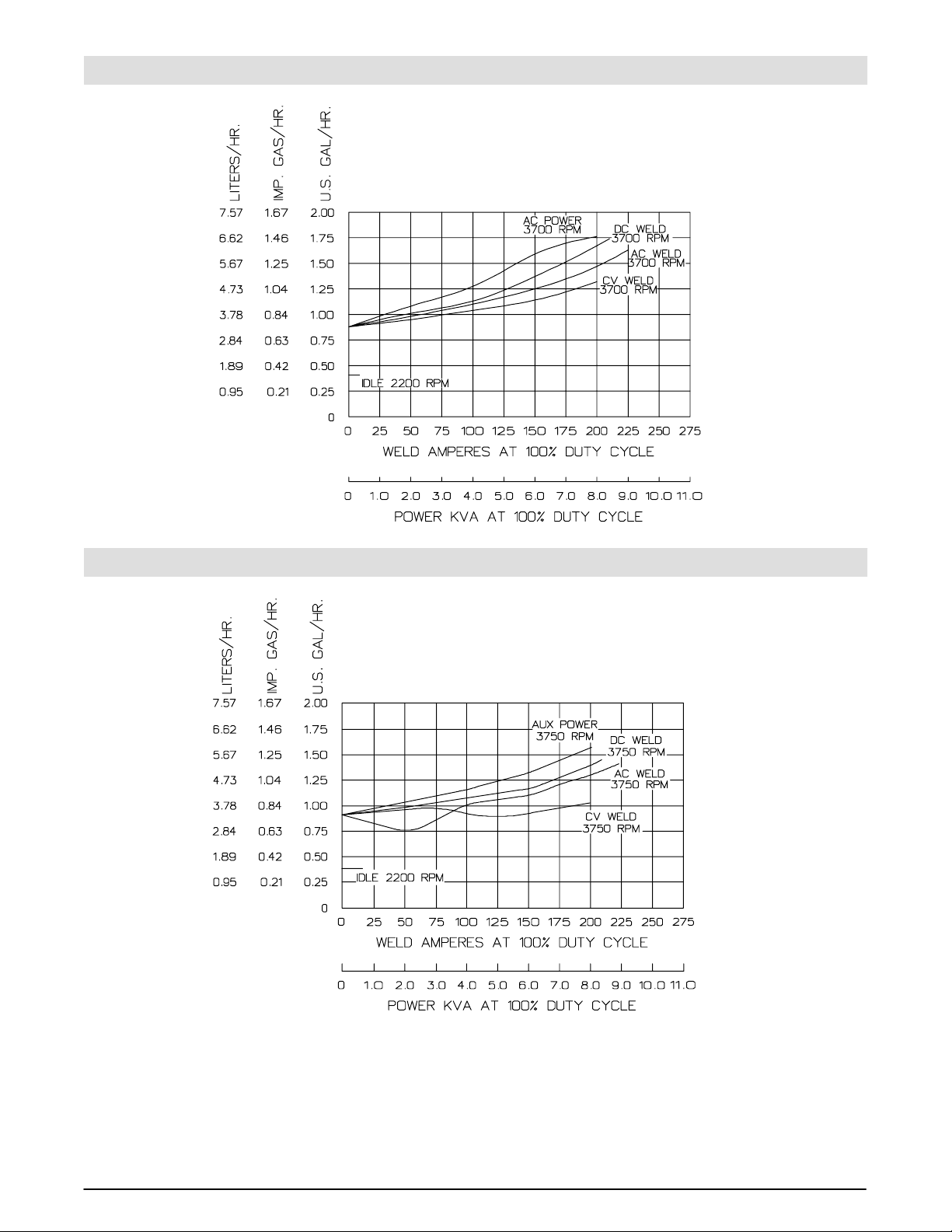
3.4 Fuel Consumption (Onan-Powered Units)
SB-119 455-A
3.5 Fuel Consumption (Kohler-Powered Units)
SB-179 939
13OM-405
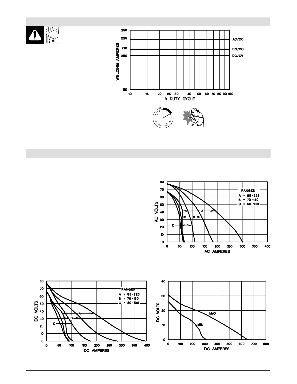
3.6 Duty Cycle
Duty cycle is the percentage of 10
minutes that unit can weld at rated
load without overheating.
Exceeding duty cycle can
damage unit and void
warranty.
3.7 Volt-Ampere Curves
The volt-ampere curve shows the
minimum and maximum voltage
and amperage output capabilities of
the welding generator. Curves of al l
other settings fall between the
curves shown.
SB-119 454-A
Continuous Welding
100% Duty Cycle at 225 Amperes CC/AC, 210 Amperes CC/DC, 200 Amperes CV/DC
ST-166 024-A / ST-166 025-A / ST-166 026-A
A. For CC/AC Mode
B. For CC/DC Mode
C. For CV/DC Mode
14 OM-405
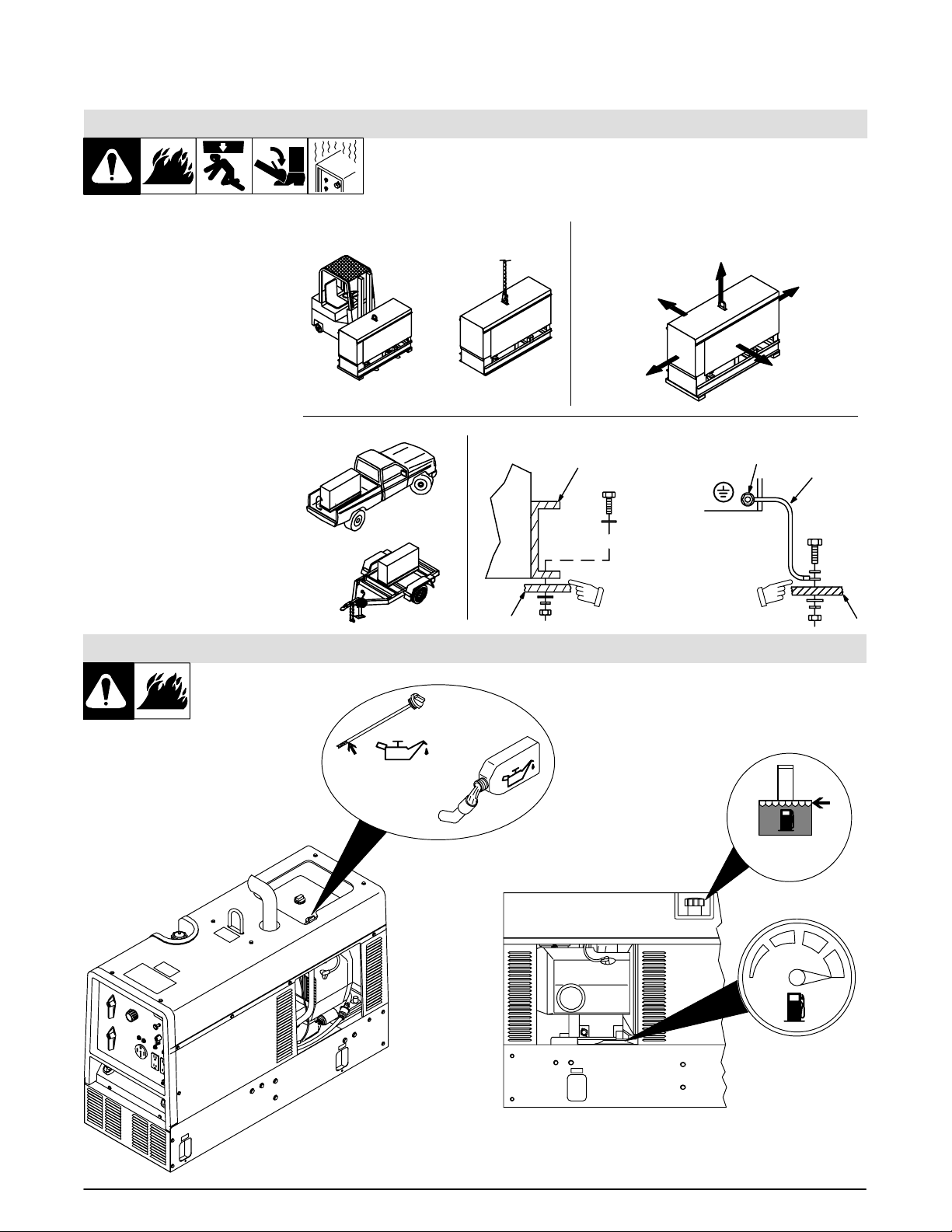
4. Installation
4.1 Installing Welding Generator
install1 1/97 – Ref. ST-800 652 / Ref. ST-800 477-A / ST-158 936-A / S-0854
1 Generator Base
2 Metal Vehicle Frame
3 Equipment Grounding
Terminal
4 Grounding Cable
Use #10 AWG or larger insulated
copper wire.
If unit does not have GFCI re-
ceptacles, use GFCI-
protected extension cord.
Movement Airflow Clearance
Do not lift unit from end.
OR
Location
OR
Grounding
2
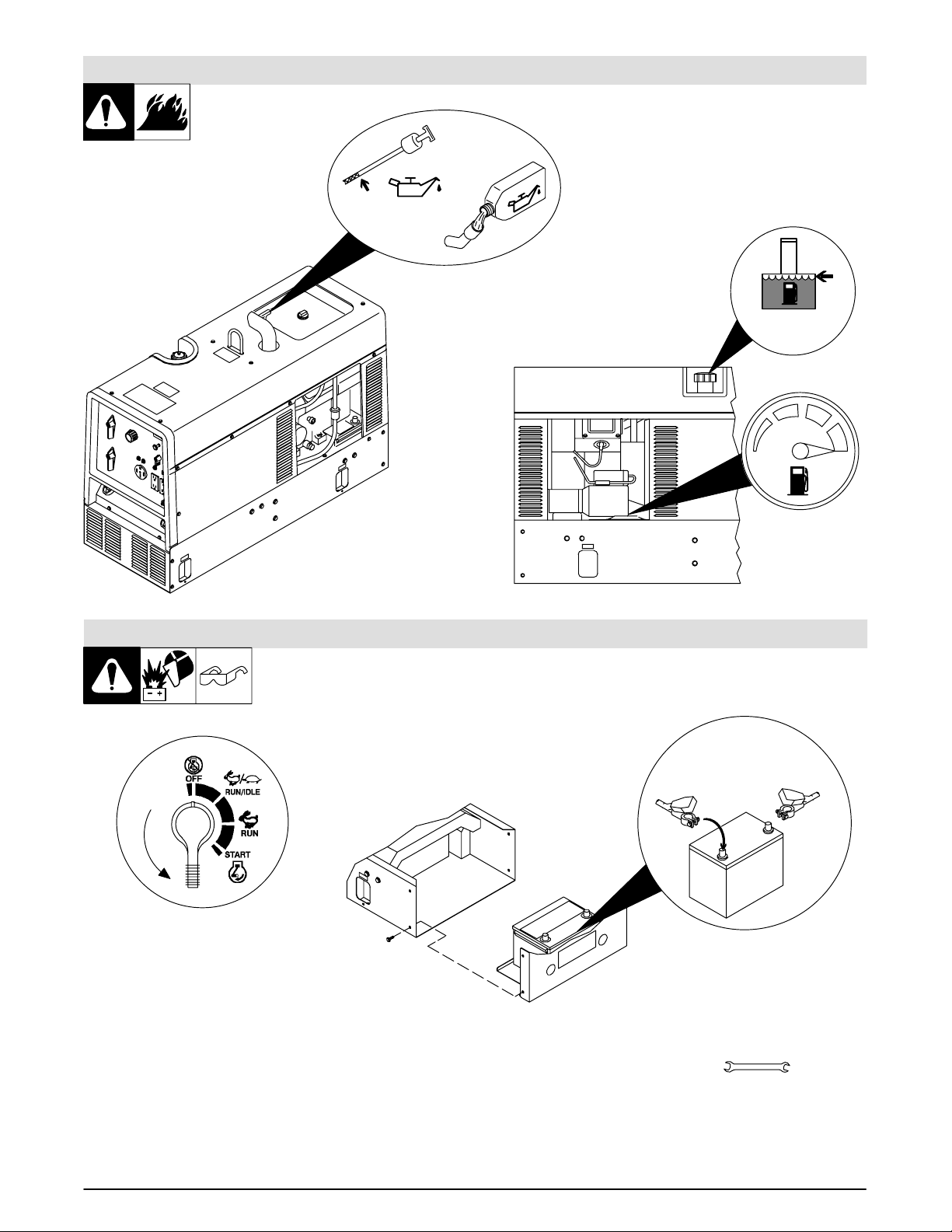
4.2 Engine Prestart Checks (Onan-Powered Units)
18 in
(460 mm)
18 in
(460 mm)
1
OR
Electrically bond generator frame to vehicle frame
by metal-to-metal contact.
18 in
(460 mm)
(460 mm)
3
GND/PE
Ref. ST-800 395-B / Ref. ST-800 392-E
18 in
(460 mm)
18 in
4
2
Check all fluids daily. Engine must
be cold and on a level surface. Unit
is shipped with 10W30 engine oil.
Engine stops if oil pressure gets too
low.
Follow run-in procedure in
engine manual.
Full
Full
Gasoline
15OM-405
4.3 Engine Prestart Checks (Kohler-Powered Units)
Check all fluids daily. Engine must
be cold and on a level surface. Unit
is shipped with 10W30 engine oil.
Engine stops if oil pressure gets too
low.
Full
Follow run-in procedure in
engine manual.
Ref. ST-801 188-B / Ref. ST-801 221-A
Full
Gasoline
4.4 Connecting the Battery
Ref. ST-800 394-C / Ref. ST-183 175-A / Ref. S-0756-D
Connect negative (–)
cable last.
+
–
Tools Needed:
3/8, 1/2 in
16 OM-405
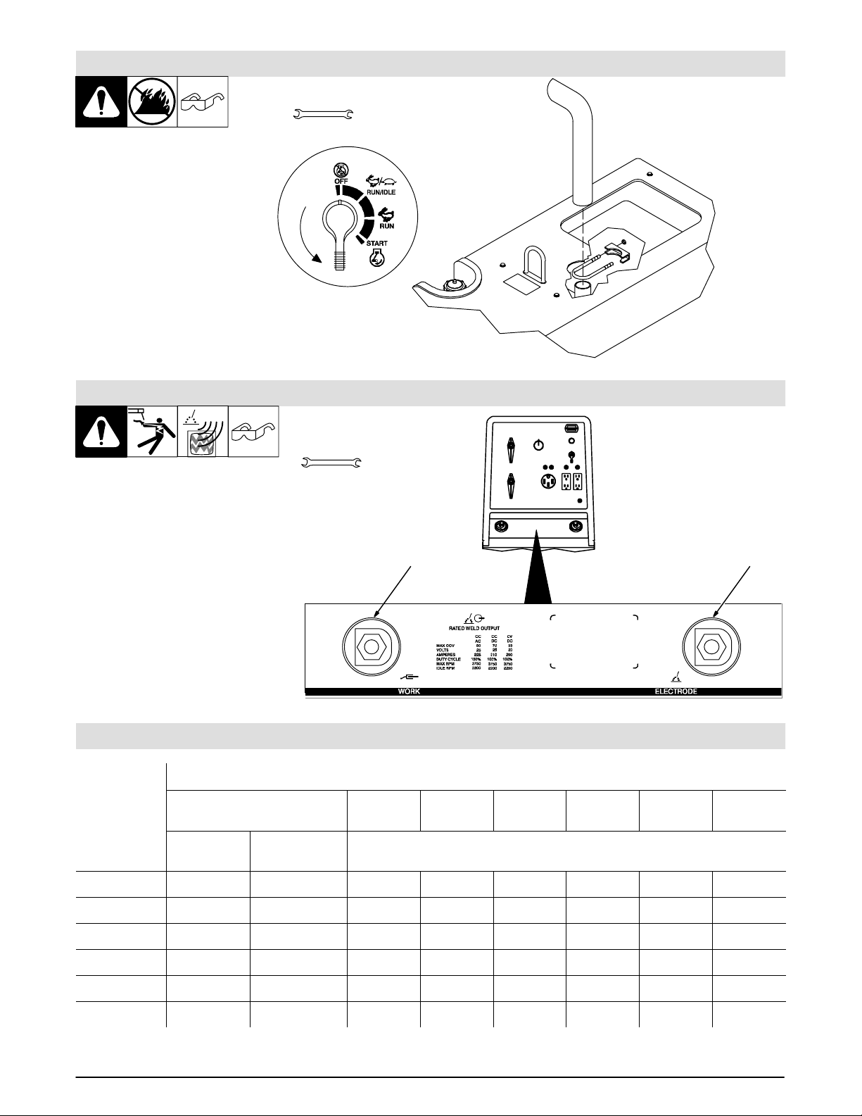
4.5 Installing Exhaust Pipe
Tools Needed:
1/2 in
Point exhaust pipe in desired
direction. I f unit is truck or trailer
mounted, point pipe away from
direction of travel.
4.6 Connecting to Weld Output Terminals
Tools Needed:
1 Work Weld Output T erminal
2 Electrode Weld Output
Terminal
Connect work cable to Work
terminal.
Connect electrode holder cable or
electrode weld cable to Electrode
terminal for Stick and MIG welding.
Connect torch cable to Electrode
terminal for TIG welding.
Use Process Selector switch to
select type of weld output (see
Section 5.1).
3/4 in
1
ST-801 681 / Ref. ST-183 175-A
ST-800 396-A / Ref. ST-183 175-A
2
4.7 Selecting Weld Cable Sizes
T otal Cable (Copper) Length in Weld Circuit Not Exceeding
Welding
100 ft (30 m) or Less
Amperes
10 – 60%
Duty Cycle
100 4 4 4 3 2 1 1/0 1/0
150 3 3 2 1 1/0 2/0 3/0 3/0
200 3 2 1 1/0 2/0 3/0 4/0 4/0
250 2 1 1/0 2/0 3/0 4/0 2-2/0 2-2/0
300 1 1/0 2/0 3/0 4/0 2-2/0 2-3/0 2-3/0
350 1/0 2/0 3/0 4/0 2-2/0 2-3/0 2-3/0 2-4/0
Weld cable size (AWG) is based on either a 4 volts or less drop or a current density of at least 300 circular mils per ampere. S-0007-D
60 – 100%
Duty Cycle
150 ft
(45 m)
200 ft
(60 m)
250 ft
(70 m)
300 ft
(90 m)
10 – 100% Duty Cycle
350 ft
(105 m)
400 ft
(120 m)
17OM-405
5. Operating Welding Generator
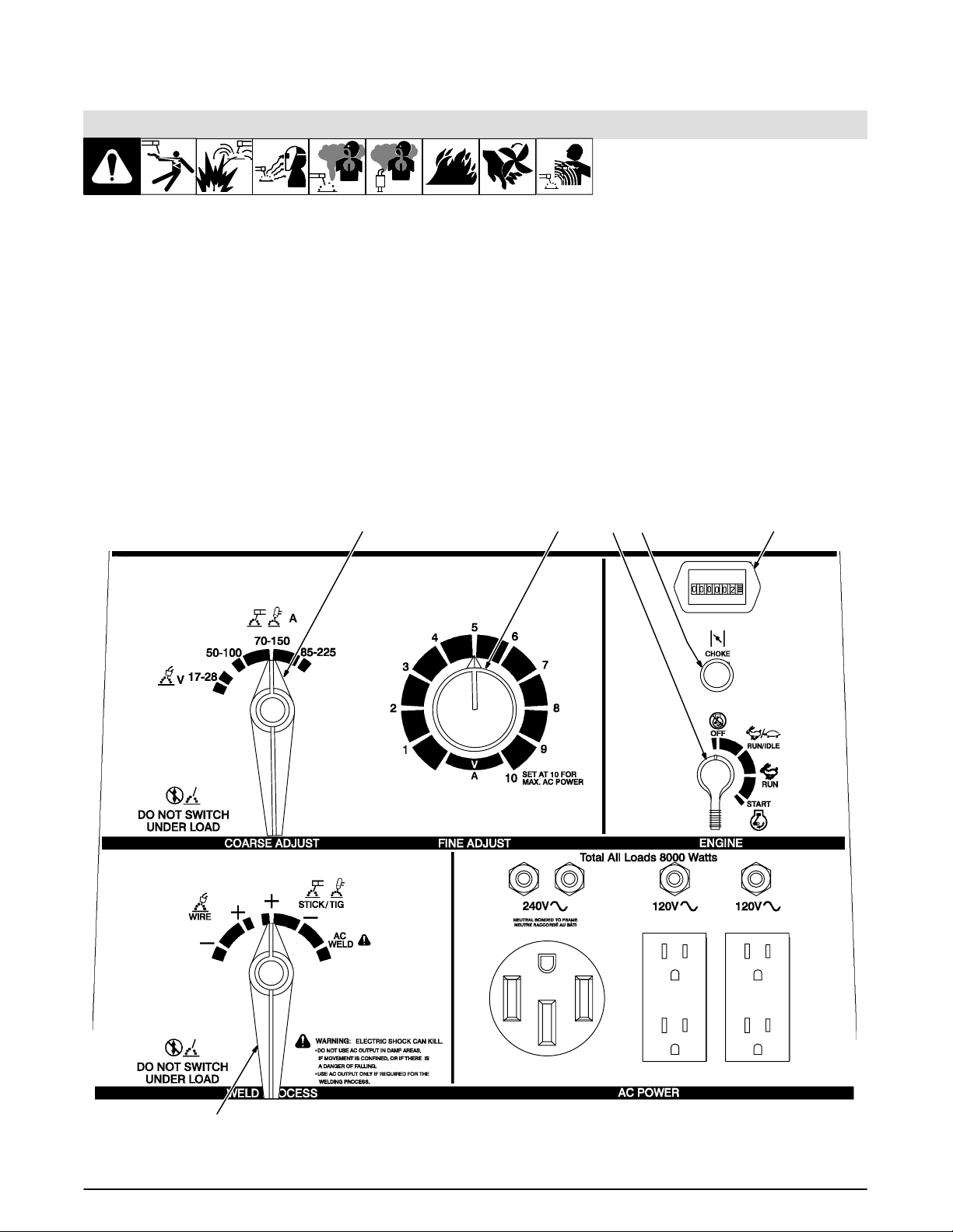
5.1 Front Panel Controls
Ref. ST-183 175-A
1 Engine Control Switch
Use switch to start engine, select speed, and
stop engine. In Run/Idle position, engine runs
at idle speed at no load, and weld/power speed
under load. In Run position, engine runs at
weld/power speed.
Place switch in Run position to operate
most MIG equipment.
2 Engine Choke Control
Use control to change engine air-fuel mix.
To Start: pull out choke and turn Engine Con-
trol switch to Start position. Release switch and
slowly push choke in when engine starts. Do
not crank engine if engine is still turning.
To Stop: turn Engine Control switch to Off posi-
tion.
3 Engine Hour Meter
4 Weld Process Selector Switch
Do not switch under load.
Use switch to select type of weld output.
Use a positive (+) position for Direct Current
Electrode Positive (DCEP) and a negative (–)
position for Direct Current Electrode Negative.
Use AC position for alternating current.
5 Coarse Adjust Switch
Do not switch under load.
6
Use switch to select weld amperage range
when W eld Process Selector switch is in Stick/
Tig position, or voltage range when switch is in
Wire position.
For best arc starts, use lowest amperage
range possible.
6 Fine Adjust Control
Use control to select weld amperage (Stick/
Tig) or voltage (Wire) within the range selected
by the Coarse Adjust switch. Control may be
adjusted while welding. Weld output would be
110 A DC based on control settings shown
(50% o f 7 0 t o 150 A). Set control at 10 for maximum auxiliary power.
135 2
4
18 OM-405
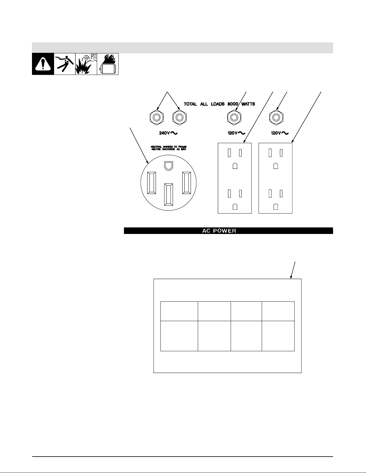
6. Operating Auxiliary Equipment
6.1 Standard Receptacles
If unit does not have GFCI re-
ceptacles, use GFCI-
protected extension cord.
Auxiliary power decreases as
weld current increases.
Set Fine Adjust control R1 at 10
for full auxiliary power.
1 240 V 50 A AC Receptacle
RC1
RC1 supplies 60 Hz single-phase
power at weld/power speed. Maximum output is 8 kVA/kW.
2 120 V 15 A AC Duplex
Receptacle RC2
3 120 V 15 A AC Duplex
Receptacle RC3
RC2 and RC3 supply 60 Hz single-
phase power at weld/power speed.
Maximum output from RC2 or RC3
is 2.4 kVA/kW. (CSA : 1.8 kV A/kW).
4 Circuit Breakers CB1 and
CB2
CB1 and CB2 protect RC1 from
overload. If CB1 or CB2 opens,
RC1 and one of the 120 volt receptacles does not work. 120 volts may
still be present at RC1.
5 Circuit Breaker CB3
6 Circuit Breaker CB4
CB3 protects RC2 and CB4 pro-
tects RC3 from overload. If a circuit
breaker opens, the recepta cl e do es
not work.
Press button to reset circuit
breaker . I f breaker continues to
open, contact Factory
Authorized Service Agent.
Combined output of all receptacles
limited to 8 kVA/kW rating of the
generator.
EXAMPLE: If 20 A is drawn from
each 120 V duplex receptacle, only
13 A is available at the 240V
receptacle:
2 x (120 V x 20 A) + (240 V x 13 A)
= 7.9 kVA/kW
7 Auxiliary Power While
Welding Label
1
456
SIMULTANEOUS WELDING AND POWER
WITH FINE ADJUST SET AT 10
Weld Current
In Amperes
210
140
90
See Owner’s Manual for additional information.
Total Power
In Watts
1000
4300
6000
120V
Receptacle Receptacle
Amperes Amperes
8
36
50
2
240V
4
18
25
S-166 360-A
Ref. ST-183 175-A
3
7
19OM-405
 Loading...