

Miller AugmentedArc Owner's Manual

OM-278680A 2019-08
Processes
Stick (SMAW) Welding
MIG (GMAW) Welding
Flux Cored (FCAW) Welding
TIG (GTAW) Welding
Description
Arc Welding Training System
AugmentedArc
®
Welding Training System
For product information,
Owner’s Manual translations,
and more, visit
www.MillerWelds.com
File: Accessory

From Miller to You
Thank you and congratulations on choosing Miller. Now you can get
the job done and get it done right. We know you don’t have time to do
it any other way.
That’s why when Niels Miller first started building arc welders in 1929,
he made sure his products offered long-lasting value and superior
quality. Like you, his customers couldn’t afford anything less. Miller
products had to be more than the best they could be. They had to be the
best you could buy.
Today, the people that build and sell Miller products continue the
tradition. They’re just as committed to providing equipment and service
that meets the high standards of quality and value established in 1929.
This Owner’s Manual is designed to help you get the most out of your
Miller products. Please take time to read the Safety Precautions. They
will help you protect yourself against potential hazards on the worksite.
We’ve made installation and operation quick
and easy. With Miller, you can count on
years of reliable service with proper
maintenance. And if for some reason the unit
needs repair, there’s a Troubleshooting
section that will help you figure out what the
problem is, and our extensive service
network is there to help fix the problem.
Warranty and maintenance information for
your particular model are also provided.
Miller is the first welding
equipment manufacturer in
the U.S.A. to be registered to
the ISO 9001 Quality System
Standard.
Working as hard as you do
− every power source from
Miller is backed by the most
hassle-free warranty in the
business.
Miller Electric manufactures a full line
of welders and welding-related equipment.
For information on other quality Miller
products, contact your local Miller distributor to receive the latest full
line catalog or individual specification sheets. To locate your nearest
distributor or service agency call 1-800-4-A-Miller, or visit us at
www.MillerWelds.com on the web.
Mil_Thank1
2019−01

TABLE OF CONTENTS
SECTION 1 − SAFETY PRECAUTIONS − READ BEFORE USING 1.................................
1-1. Symbol Usage 1.......................................................................
1-2. Welding Training System Hazards 1.......................................................
1-3. Proposition 65 Warnings 1...............................................................
1-4. Principal Safety Standards 1.............................................................
SECTION 2 − CONSIGNES DE SÉCURITÉ − LIRE AVANT UTILISATION 2...........................
2-1. Symboles utilisés 2.....................................................................
2-2. Dangers liés au système de formation en soudure 2.........................................
2-3. Proposition californienne 65 Avertissements 2..............................................
2-4. Principales normes de sécurité 2.........................................................
SECTION 3 − DEFINITIONS 3..................................................................
3-1. Miscellaneous Symbols And Definitions 3..................................................
SECTION 4 − SPECIFICATIONS 4..............................................................
4-1. Introduction 4.........................................................................
4-2. System Features And Benefits 4.........................................................
4-3. AugmentedArc Complete Package 4......................................................
4-4. Serial Number And Rating Label Location 4................................................
4-5. Unit Specifications 5....................................................................
4-6. Software Licensing Agreement 5.........................................................
4-7. Environmental Specifications 6...........................................................
SECTION 5 − INSTALLATION 6................................................................
5-1. Selecting A Location 6..................................................................
5-2. Simulator Components 7................................................................
5-3. Installing The Training System − Standalone Configuration 8..................................
5-4. Installing The Training System − Classroom Configuration 9...................................
5-5. Connecting Simulator To An External Monitor 10.............................................
5-6. Assembling AR MIG Gun 10..............................................................
5-7. Assembling AR TIG Torch 11.............................................................
5-8. Assembling AR Stick Electrode 12.........................................................
5-9. AR Stick Electrode, MIG Gun, TIG Torch, And Workpieces 13..................................
5-10. AR Welding Helmet 14...................................................................
5-11. Making Helmet Adjustments 14............................................................
5-12. Connecting Weld Cables 15..............................................................
SECTION 6 − SYSTEM CONTROLS AND COMPONENTS 16.......................................
6-1. Simulator Controls 16....................................................................
SECTION 7 − OPERATION 17...................................................................
7-1. Equipment Setup 17.....................................................................
7-2. Getting Started 17.......................................................................
A. Login Screens 17.......................................................................
B. Course Selection 18.....................................................................
C. Lighting Calibration 19...................................................................
D. Correcting Improper Weld Setting 21.......................................................
E. Determining Correct Position Of MIG Gun/Electrode And AR Helmet 23..........................
F. Course Analysis 26.....................................................................
SECTION 8 − SYSTEM SETTINGS 27............................................................
8-1. Accessing Administrator Home Screen 27..................................................
8-2. Changing System Configuration 27........................................................
A. Changing System Language Setting 27.....................................................
B. Changing System Units And Standards 27..................................................

TABLE OF CONTENTS
SECTION 8 − SYSTEM SETTINGS (Continued) 27.................................................
C. Changing System Date And Time 28.......................................................
D. Changing System Mode 28...............................................................
E. Changing Simulation Settings 28..........................................................
F. Changing Lighting Calibration Options 28...................................................
G. Change WiFi Access Point Settings 28.....................................................
H. Restoring Factory Configuration 28........................................................
8-3. Software Updates 29....................................................................
A. Software Updates − Standalone Mode 29...................................................
B. Software Updates − Classroom Mode 29....................................................
8-4. T
roubleshooting
8-5. Check Components 31...................................................................
A. Checking Front Panel Functions 31........................................................
B. Checking Audio 31......................................................................
C. Checking Displays 31....................................................................
D. Checking Camera Set 31.................................................................
E. Calibrating Electrode Retraction 32........................................................
F. Configuring TIG Foot Pedal 32............................................................
8-6. Cameras 33............................................................................
A. Configure Camera Set 33................................................................
B. Restore Factory Camera Calibration 38.....................................................
8-7. Video Device Settings 39.................................................................
A. Lighting Calibration 39...................................................................
B. Temperature Setting (Figure 8-24) 39.......................................................
C. Intensity Setting (Figure 8-25) 40..........................................................
D. Custom Settings 40.....................................................................
SECTION 9 − USING THE TEACHER SOFTWARE 42..............................................
9-1. Installing The Teacher Software Program 42.................................................
9-2. Using The Teacher Software 45...........................................................
A. Student Home Page (Figure 9-11) 46.......................................................
B. Adding A Student (Figure 9-12) 48.........................................................
C. Editing Student Information 49............................................................
D. Deleting A Student (Figure 9-14) 50........................................................
9-3. Module Management 50..................................................................
A. Task Information 51.....................................................................
B. Adding A Module (Figure 9-17 And Figure 9-19) 51...........................................
C. Designing The Welding Exercise (Figure 9-22) 53............................................
D. Scoring 55.............................................................................
E. Copy Module 55........................................................................
9-4. Course Management 57..................................................................
A. Adding Courses 57......................................................................
B. Editing A Course 58.....................................................................
C. Course History 59.......................................................................
9-5. Reviewing Student Activity And Results 59..................................................
A. Student Information (Figure 9-35) 59.......................................................
B. Virtual Classroom 62....................................................................
C. Creating Reports 62.....................................................................
9-6. Account And Settings 63.................................................................
A. Manage Accounts 63....................................................................
B. Settings 63.............................................................................
SECTION 10 − INSTALLING OPTIONAL MAGNIFYING LENS 65....................................
SECTION 11 − MAINTENANCE AND STORAGE 66................................................
11-1. Routine Maintenance 66.................................................................
SECTION 12 − TROUBLESHOOTING 66.........................................................
12-1. Troubleshooting Table 66.................................................................
SECTION 13 − RECONFIGURING STANDALONE ROUTER FOR CLASSROOM MODE 67.............
SECTION 14 − PARTS LIST 68..................................................................
WARRANTY
30......................................................................
SECTION 1 − SAFETY PRECAUTIONS −
READ BEFORE USING
Protect yourself and others from injury — read, follow, and save these important safety precautions and operating instructions.
1-1. Symbol Usage
AugArc 2018-01
DANGER! − Indicates a hazardous situation which, if
not avoided, will result in death or serious injury. The
possible hazards are shown in the adjoining symbols
or explained in the text.
Indicates a hazardous situation which, if not avoided,
could result in death or serious injury. The possible
hazards are shown in the adjoining symbols or explained in the text.
NOTICE − Indicates statements not related to personal injury.
1-2. Welding Training System Hazards
The symbols shown below are used throughout this manual
to call attention to and identify possible hazards. When you
see the symbol, watch out, and follow the related instructions
to avoid the hazard. The safety information given below is
only a summary of the more complete safety information
found in the Safety Standards listed in Section 1-4. Read and
follow all Safety Standards.
Only qualified persons should install, operate, maintain, and
repair this equipment. A qualified person is defined as one
who, by possession of a recognized degree, certificate, or
professional standing, or who by extensive knowledge, training and experience, has successfully demonstrated ability to
solve or resolve problems relating to the subject matter, the
work, or the project and has received safety training to recognize and avoid the hazards involved.
READ INSTRUCTIONS.
Read and follow all labels and the Owner’s
Manual carefully before installing, operating, or
servicing unit. Read the safety information at
the beginning of the manual and in each
section.
Use only genuine replacement parts from the manufacturer.
Perform installation, maintenance, and service according to the
Owner’s Manuals, industry standards, and national, state, and
local codes.
Do not repair, modify, or disassemble the training system or use
with parts or accessories not supplied by the manufacturer. Use
only approved components and accessories from the
manufacturer.
Be sure all hardware is properly tightened.
Indicates special instructions.
This group of symbols means Warning! Watch Out! ELECTRIC
SHOCK, MOVING PARTS, and HOT PARTS hazards. Consult symbols and related instructions below for necessary actions to avoid the
hazards.
Do not use the training system until you are sure it is correctly as-
sembled and working properly.
Before each use, inspect the training system for damage and verify
it is secure and installed properly.
Use the training system only as specified in the manual.
ELECTRIC SHOCK can kill.
Touching live electrical parts can cause fatal shocks
or severe burns.
Do not touch live electrical parts.
Disconnect input power before installing or servicing this
equipment.
Keep cords dry, free of oil and grease, and protected from hot
metal and sparks.
Frequently inspect input power cord and ground conductor for
damage or bare wiring – replace immediately if damaged – bare
wiring can kill.
Use only well-maintained equipment. Repair or replace dam-
aged parts at once. Maintain unit according to the manual.
Keep all panels and covers securely in place.
Do not use the training system during an electrical storm. Turn
off equipment and disconnect input power until risk of lightning
has passed.
Always verify the supply ground − check and be sure that cord
plug is connected to a properly grounded receptacle outlet.
Do not use equipment in damp or wet conditions.
1-3. Proposition 65 Warnings
WARNING: Cancer and Reproductive Harm − www.P65W
arnings.ca.gov
1-4. Principal Safety Standards
Safety Requirements for Electrical Equipment for Measurement, Control, and Laboratory Use — Part 1: General requirements, CAN/CSA
Standard C22.2 No. 61010−1−12, from Canadian Standards Association, Standards Sales, 5060 Spectrum Way, Suite 100, Mississauga,
Ontario, Canada L4W 5NS (phone: 800-463-6727,
website: www.csagroup.org).
OM-278680 Page 1
SECTION 2 − CONSIGNES DE SÉCURITÉ − LIRE AVANT UTILISATION
7
Pour écarter les risques de blessure pour vous−même et pour autrui — lire, appliquer et ranger en lieu sûr ces consignes relatives
aux précautions de sécurité et au mode opératoire.
2-1. Symboles utilisés
AugArc_2018−01_fre
DANGER! − Indique une situation dangereuse qui si on
l’évite pas peut donner la mort ou des blessures graves.
Les dangers possibles sont montrés par les symboles
joints ou sont expliqués dans le texte.
Indique une situation dangereuse qui si on l’évite pas
peut donner la mort ou des blessures graves. Les dangers possibles sont montrés par les symboles joints ou
sont expliqués dans le texte.
AVIS − Indique des déclarations pas en relation avec des blessures
personnelles.
Indique des instructions spécifiques.
Ce groupe de symboles veut dire Avertissement! Attention! DANGER
DE CHOC ELECTRIQUE, PIECES EN MOUVEMENT, et PIECES
CHAUDES. Consulter les symboles et les instructions ci-dessous y
afférant pour les actions nécessaires afin d’éviter le danger.
2-2. Dangers liés au système de formation en soudure
Les symboles représentés ci-dessous sont utilisés dans ce manuel pour attirer l’attention et identifier les dangers possibles. En
présence de l’un de ces symboles, prendre garde et suivre les
instructions afférentes pour éviter tout risque. Les instructions
en matière de sécurité indiquées ci-dessous ne constituent
qu’un sommaire des instructions de sécurité plus complètes
fournies dans les normes de sécurité énumérées dans la Section 2-4. Lire et observer toutes les normes de sécurité.
L
’installation,
doivent être confiés qu’à des personnes qualifiées. Une
personne qualifiée est définie comme celle qui, par la
possession
statut professionnel, ou qui, par une connaissance, une formation et une expérience approfondies, a démontré avec
succès sa capacité à résoudre les problèmes liés à la tâche,
le travail ou le projet et a reçu une formation en sécurité afin
de reconnaître et d’éviter les risques inhérents.
l’utilisation, l’entretien et les réparations ne
d’un diplôme reconnu, d’un certificat ou d’un
LIRE LES INSTRUCTIONS.
Lire et appliquer les instructions sur les
étiquettes
lation, l’utilisation ou l’entretien de l’appareil.
Lire les informations de sécurité au début du
N’utiliser que les pièces de rechange recommandées par le
constructeur.
Effectuer l’installation, l’entretien et toute intervention selon les
manuels d’utilisateurs, les normes nationales, provinciales et de
l’industrie,
Ne pas réparer, modifier ou démonter le système de formation,
et ne pas l’utiliser avec des pièces ou accessoires non fournis
par le fabricant. Utiliser uniquement des composants et
accessoires approuvés par le fabricant.
S’assurer que toute la quincaillerie est bien serrée.
Ne pas utiliser le système de formation avant d’être certain qu’il est
bien monté et qu’il fonctionne correctement.
manuel et dans chaque section.
ainsi que les codes municipaux.
et le Mode d’emploi avant l’instal-
Avant chaque utilisation, inspecter le système de formation pour
déceler tout signe de dommage et s’assurer qu’il est bien installé et
maintenu correctement.
Utiliser le système de formation seulement conformément au
manuel.
Ne pas toucher aux pièces électriques sous tension.
Couper le courant avant d’installer ou de faire l’entretien de cet
équipement.
En effectuant les raccordements d’entrée, fixer d’abord le
conducteur de mise à la terre approprié et contre-vérifier les
connexions.
Les câbles doivent être exempts d’humidité, d’huile et de
graisse; protégez−les contre les étincelles et les pièces
métalliques
N’utiliser qu’un matériel en bon état. Réparer ou remplacer
sur-le-champ les pièces endommagées. Entretenir l’appareil
conformément
Maintenir solidement en place tous les panneaux latéraux et les
capots.
Ne pas utiliser le système de formation pendant un orage
électrique.
l’alimentation
d’éclairs.
Toujours vérifier la terre du cordon d’alimentation − Vérifier et
s’assurer que la fiche du cordon est raccordée à une prise
correctement mise à la terre.
Ne pas utiliser l’équipement en conditions humides ou
mouillées.
UNE DÉCHARGE ÉLECTRIQUE peut
entraîner la mort.
Tout contact avec des pièces électriques sous
tension peut causer un choc mortel ou des brûlures
graves.
chaudes.
à ce manuel.
Mettre l’équipement hors tension et débrancher
électrique jusqu’à ce que soit éliminé le risque
2-3. Proposition californienne 65 Avertissements
AVERTISSEMENT : cancer et troubles de la reproduction − www.P65W
2-4. Principales normes de sécurité
Safety Requirements for Electrical Equipment for Measurement, Control, and Laboratory Use — Part 1: General requirements, CAN/CSA
Standard C22.2 No. 61010−1−12, from Canadian Standards Association, Standards Sales, 5060 Spectrum Way, Suite 100, Mississauga,
Ontario, Canada L4W 5NS (phone: 800-463-6727,
website: www.csagroup.org).
OM-278680 Page 2
arnings.ca.gov
.
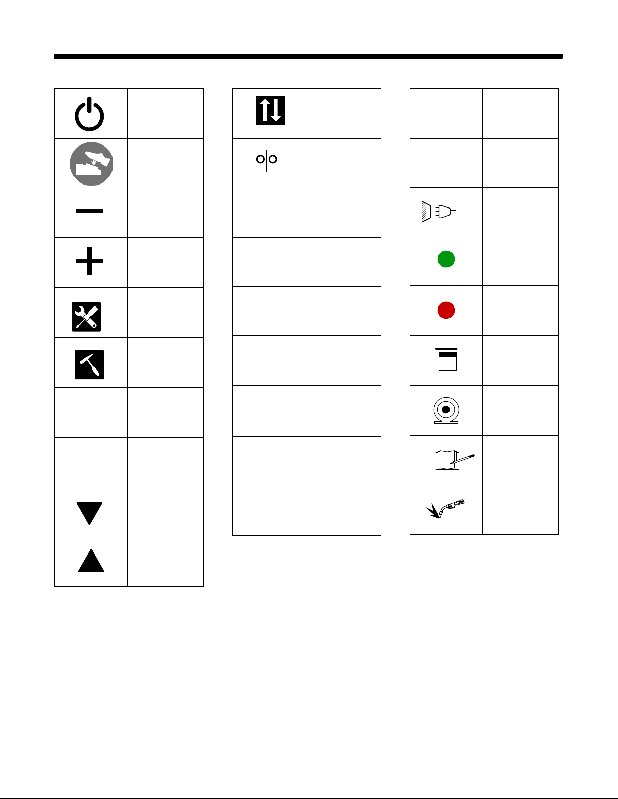
SECTION 3 − DEFINITIONS
3-1. Miscellaneous Symbols And Definitions
Power On/Off
TIG Foot Pedal
Enabled
Decrease
Increase
Settings
Clean Slag
Pass
AR
A
V
2T
4T
Change Transfer
Mode
Wire Feed
Augmented Reality
Amperage
Voltage
Press To Start
Weld; Release To
Stop Weld
Press And
Release To Start
Weld; Press And
Release To Stop
Weld
AC
IP
Alternating Current
Internal Protection
Rating
Input Plug And
Cord
Connected To
Network
Disconnected
From Network
Connected And
Seeing Theory
Connected And
Analyzing An
Exercise
X
Fail
Down
Up
DC+
DC−
DC Electrode
Positive
DC Electrode
Negative
Connected And
Doing A Quiz
Connected And
Performing An
Exercise
OM-278680 Page 3
SECTION 4 − SPECIFICATIONS
4-1. Introduction
The AugmentedArc is an augmented reality (AR) welding training system that provides the new student or the experienced welder the opportunity to
develop, enhance, or verify their welding abilities through an interactive, simulated welding process on a variety of weld joint configurations. This
product is designed to help welding students acquire the necessary welding knowledge, capacities, abilities, welding sensations and skills, thereby
saving the time and money normally spent training in a live welding situation. It is an educational solution to help both students and trainers improve their
learning experience and enhance results and qualifications. The system can be installed as a standalone or classroom configuration.
After the AugmentedArc system is installed, the user turns on the training system, selects the desired welding assignment, puts on the augmented
reality (AR) welding helmet and welding gloves (welding gloves are recommended to simulate a live welding experience), and begins the simulated
welding activity. The cameras and AR markers convey the weld data (gun angles, gun speed, contact tip to work distance [CTWD], aim) to the system
microprocessor, which compares it to the specified weld parameters of the assignment selected. The system evaluates the weld data and grades the
student’s performance.
The AugmentedArc instruction is complementary to training with live welding equipment. To complete their welding training, students should also
practice their acquired skills by welding under the supervision of qualified persons in a safe welding environment.
NOTICE − Do not install or use the Augmented Arc in the same area as live welding equipment.
4-2. System Features And Benefits
S Advanced computer simulation techniques using artificial vision technology create a realistic welding environment.
Teacher software allows the instructor to adapt their training programs to the AugmentedArc system. The instructor can manage and monitor
student activity and progress from a PC (personal computer) (see Section 9).
Analysis mode allows all of the welding exercises performed in the simulator to be visualized, providing detailed results of all of the welding
parameters.
System allows for remote maintenance and software updates, and is adaptable to meet specific training requirements.
The system configuration can be installed as a standalone or classroom application. The standalone application includes a simulator and a
router, and all of the information is saved on the unit. The classroom application can include multiple simulators, a router, and a controller. All
of the information is saved on the controller.
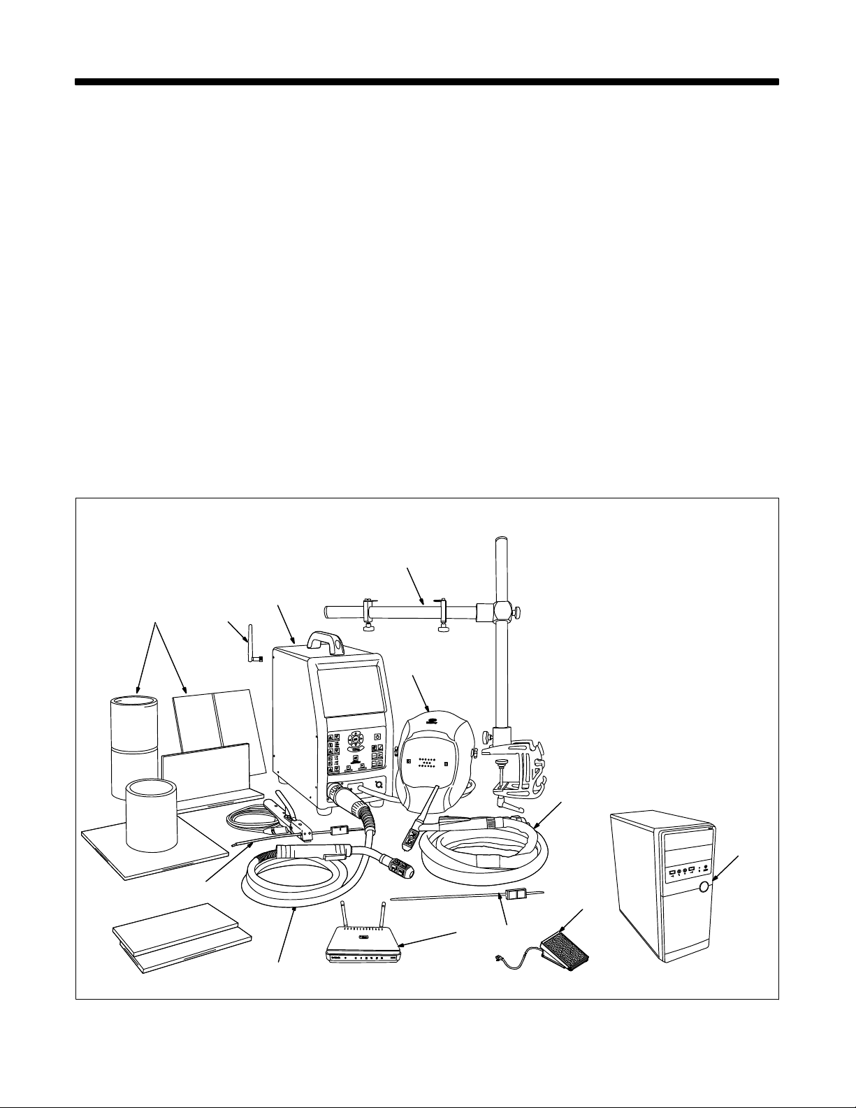
4-3. AugmentedArc Complete Package
1
10
11
Input power and Ethernet cables
are not shown.
3
2
1 Simulator
2 Helmet
3 Workpiece Stand
4 TIG (GTAW) Torch And Cable
5 TIG Filler Rod
6 TIG Foot Pedal And Adapter
Cable (Optional)
7 Router
8 MIG (GMAW) / FCAW Gun
And Cable
9 Stick (SMAW) Electrode
Holder And Cable
10 Workpieces (Five Total)
11 WiFi Antenna (Two Total)
12 Controller (Optional, For
Classroom Configuration Only)
4
12
9
161-93 / 161-97 / 161-100 / Ref. 805 465-A
7
8
5
6
4-4. Serial Number And Rating Label Location
The serial number and rating information for this product is located on the back of the unit. Use rating label to determine input power requirements, and to
register for free software upgrades. For future reference, write serial number in space provided on back cover of this manual.
OM-278680 Page 4

4-5. Unit Specifications
Dimensions (L x W x H) Simulator: 17.25 x 9.38 x 21 in. (438 x 238 x 533 mm)
Weight Simulator: 20.7 lb (9.4 kg) AR Welding Helmet: 1.97 lb (0.89 kg)
Simulator and Helmet (including cables): 23.8 lb (10.8 kg)
Input Power 80 to 264 Volts AC, 0.9A (230 VAC) to 1.8A (115 VAC), 50/60 Hz
External VGA Port Resolution External HDMI Port Resolution: 1024 x 768 Pixels
Display Port Resolution: 1024 x 768 Pixels
Resolution during boot-up is 800 x 600 Pixels.
Simulation Modes/Processes Stick (SMAW), MIG (GMAW/FCAW), TIG (GTAW)
Software Version Displayed On System Settings Screen.
Register for free software upgrades at MillerWelds.com/register.
Computer OS: Linux
Main Monitor 9.7 in. integrated LCD monitor, 1024 x 768 resolution
PC Requirements For Installation Of Teacher
Software (See Section 9)
Supported Welding Processes Stick (SMAW), MIG (GMAW), FCAW, TIG (GTAW)
Parameters Tracked By Cameras MIG: Work Angle, Travel Angle, Travel Speed, Contact Tip To Work Distance (CTWD), Aim
Supported Joints Bead On Plate, T-Joint, Butt Joint, Lap Joint, Pipe-Plate, Pipe-Pipe
Welding Positions 1F, 2F, 3F, 4F, 1G, 2G, 3G, 4G, 5G, 6G
Workpiece Positions Horizontal, Vertical, Flat, Overhead
Voltage Selection MIG (GMAW and FCAW) 10 − 38 Volts
Amperage (Intensity) Selection Stick (SMAW), MIG (GMAW and FCAW), TIG (GTAW): 50 − 425 Amps
Polarity Selection DCEP, DCEN, AC
Shielding Gas Selection CO2, Argon-O2, Argon-CO2, And Mixtures
Wire Speed Selection MIG (GMAW and FCAW): 50 - 1000 ipm (1.27 − 25.4 m/min)
Base Material Selection Carbon Steel, Stainless Steel, Aluminum
Workpiece Thickness Selection 1/8, 1/4, 3/8 in. (3.2, 6.4, 9.5 mm)
Stick Electrode Selection E7018, E6010, E6013
Stick Electrode Diameter Selection 1/8, 3/32, 5/32 in. (2.50, 3.25, 4.00 mm)
Wire Diameter Selection Solid Wire: 0.030, 0.035, 0.045 in. (0.8, 1.0, 1.2 mm)
Filler Rod Selection 5/64, 3/32 in. (2.0 And 2.4 mm)
Real Time Guide Parameters On-Screen Help Guides Provide Corrective Feedback To User During Simulation
Teacher Software Standalone Application
Helmet Miller Black Infinity Helmet With Premium Headgear. Includes Integrated 4.8 in. LCD dis-
MIG Guns/TIG Torches Miller Brand
Stick Electrode And TIG Filler Rod Markers AR Marker Attachment
Measurements Global Setting Displays Measurements In Standard (Imperial) Or Metric
Languages English, French, Spanish
Processor: i7
RAM: 4GB DDR3L
Graphics Card: NVIDIA GTX 950
60GB Solid State Hard Drive
Operating System: Windows 7 (64 bits), Windows 8 (64 bits), Windows 10 (64 bits)
Processor: 2.2 GHz 3 MB
RAM: 4 GB
Display (min): 1366 x 768
Graphic Board: 2GB VRAM Direct X9 compatible graphics card:
NVidia GeForce: 750 or better, or 900 Mobile Series or better
Radeon: HD 6000 series or better, or HD 7000 Mobile series or better
Hard Drive: 1 GB
Stick: Work Angle, Travel Angle, Travel Speed, Arc Length, Aim
TIG: Rod Work Angle, Rod Filler Angle, Travel Angle, Travel Speed, Arc Length, Aim, Work
Angle
play (1024 x 600), and integrated speakers.
4-6. Software Licensing Agreement
The End User License Agreement and any third-party notices and terms and conditions pertaining to third-party software can be found at
https://www
.millerwelds.com/eula
and are incorporated by reference herein.
OM-278680 Page 5
4-7. Environmental Specifications
A. Temperature Specifications
Operating Temperature Range Storage/Transportation Temperature Range
41 to 113°F (5 to 45°C)
SECTION 5 − INSTALLATION
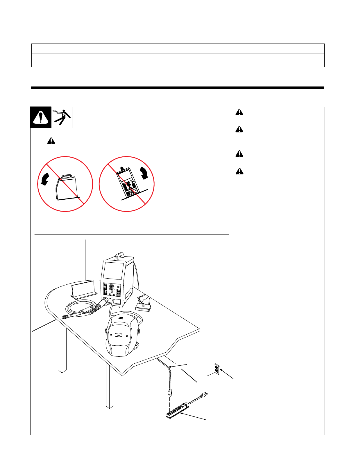
5-1. Selecting A Location
! Do not move or operate unit
where it could tip.
−4 to 140°F (−20 to 60°C)
! Only qualified persons should in-
stall, operate, maintain, and repair this unit.
! Installation must meet all Nation-
al, State, and Local Codes − have
only qualified persons make this
installation.
! Do not move unit by pulling on
simulator, router, helmet, or cables or equipment may tip.
! Do not use this equipment to sup-
port personnel, large tools, or
other material.
NOTICE − Use training system only in-
doors and away from sources of high frequency (TIG welders) and other types of
electrical interference. It may be necessary to enclose nearby electrical wiring
in conduit if unit is affected by interference.
NOTICE − Do not use training system in
damp or wet locations. Keep training
system components dry.
NOTICE − Do not position training sys-
tem where the cameras are in direct sunlight. High intensity sunlight can interfere
with gun tracking.
NOTICE − Do not install or use the Aug-
mented Arc in the same area as live
welding equipment.
1 120 Volt, 15 Amp AC Grounded
Receptacle
2 Input Power Cord(s)
3 Surge-Protected Power Strip
Position unit near the 120 volt AC receptacle but away from obstructions that
may restrict movement of cables and
gun/electrode
holders.
Temp_2016-07
A 120 volt AC, 15 amp individual
branch circuit protected by time de-
lay fuses or circuit breaker is
required. Use of a surge-protected
2
power strip is recommended.
OM-278680 Page 6
1
3
Loc_AugArc
2016-08 / 161-092
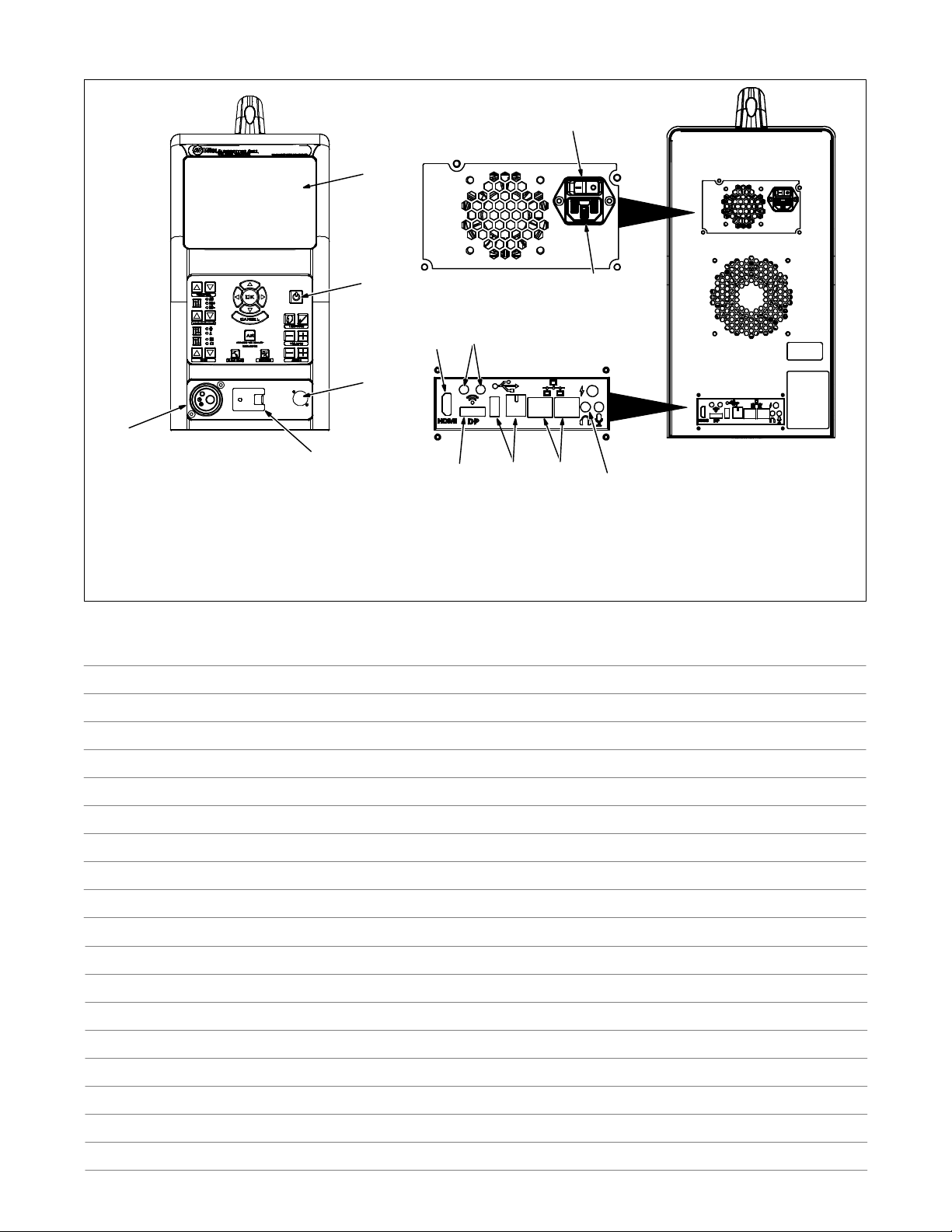
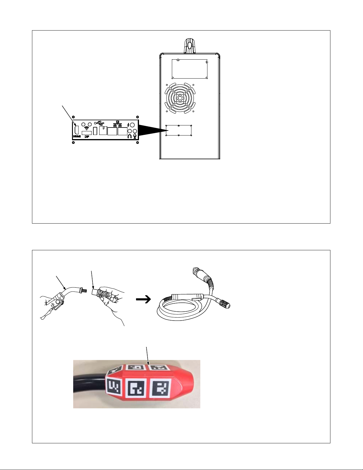
5-2. Simulator Components
6
1
5
1 Display Screen
2 Control Panel (See Section 6-1)
3 Stick Cable And TIG Foot Pedal
Receptacle
4 AR Helmet Cable (Cable Not Shown)
Notes
2
10
8
3
4
13
5 MIG/FCAW And TIG Cable Receptacle
6 Simulator Input Power Switch
7 120 Volt AC Input Receptacle
8 HDMI Receptacle
9 Audio Output Receptacle
11
12
7
9
10 WiFi Antenna Receptacles
11 USB Receptacle
12 Internet/Ethernet Receptacle
13 DisplayPort Receptacle
276 687-A
OM-278680 Page 7
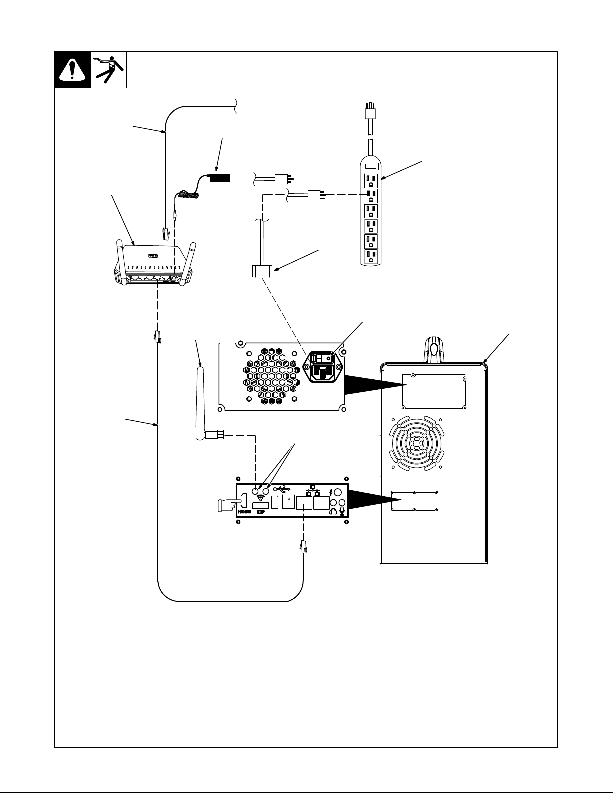
5-3. Installing The Training System − Standalone Configuration
120 V, 15A AC
IP Network
7
2
1
8
9
5
3
4
7
See Section 5-5
to connect an
external monitor
to the HDMI
receptacle.
Use standalone configuration when
system is not set up with optional controller.
1 Standalone Router
2 Router Power Cable
3 120 Volt 15 Amp AC Receptacle Or
Power Strip
Use of a surge-protected power strip is
recommended.
For best results, locate router within 39
6
in. (1 m) of simulator.
4 Simulator
5 WiFi Antenna (One Shown)
6 WiFi Receptacles
Connect both WiFi antennas to WiFi receptacles on simulator.
7 Network (Ethernet) Cables (Optional)
Connect IP network cable to Internet receptacle on back of router (either receptacle
can be used). Connect additional network
276 687 / 161-94
cable from router receptacle LAN1 to Ethernet receptacle on back of simulator.
8 Simulator Power Cable
Connect one end of simulator power cable
to simulator. Connect other end of power
cord to 120 volt AC receptacle.
9 Input Power Switch
Place Power switch in On position.
Information on using the Teacher Soft-
ware program is provided in Section 9).
OM-278680 Page 8
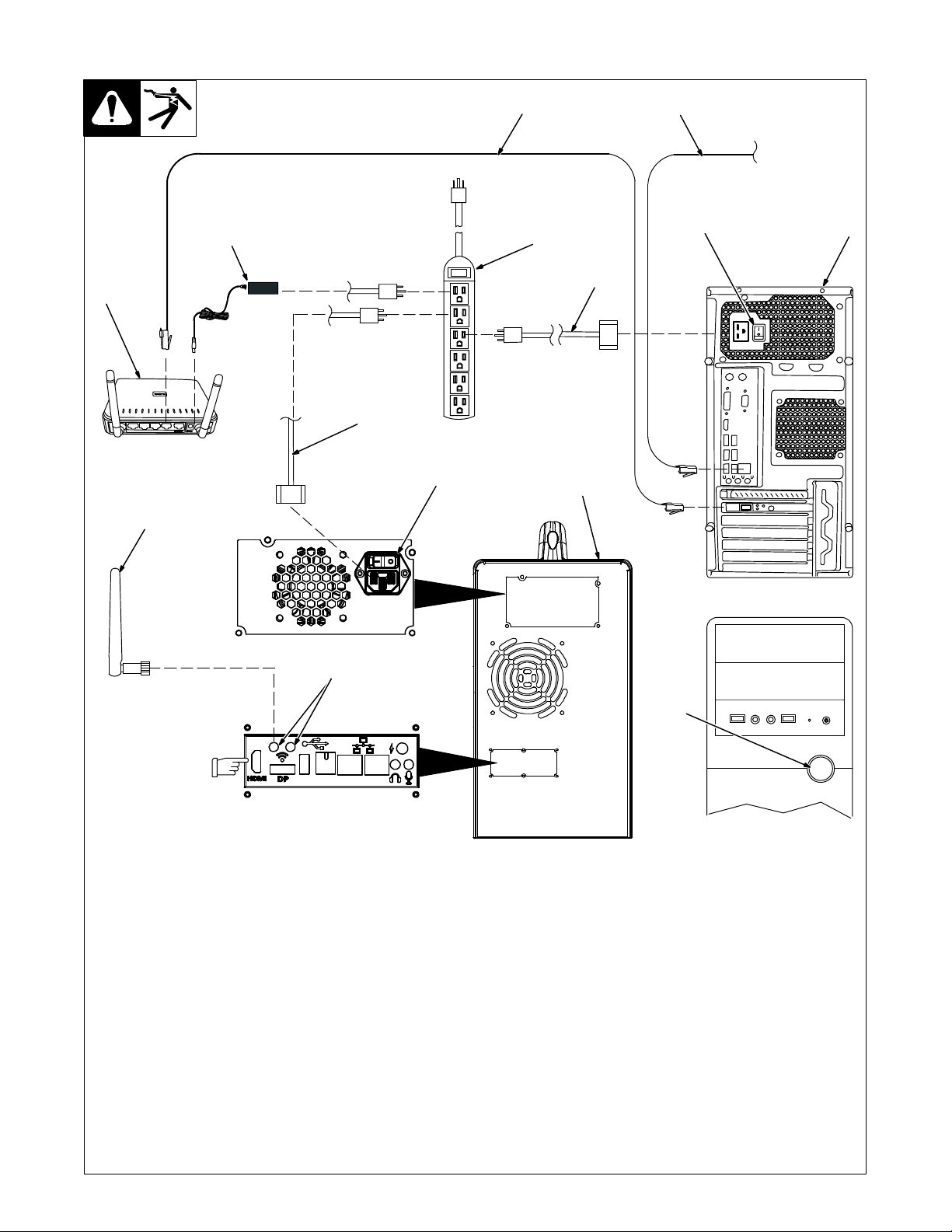
5-4. Installing The Training System − Classroom Configuration
5
Local AugmentedArc Network
120 V, 15A AC
2
1
13
14
11
3
7
10
4
IP Network
(Internet)
8
Controller
Back
6
See Section 5-5 to
connect an external
monitor to the HDMI
receptacle.
1 Classroom Router
It is very important that only the Class-
room Router is used and that all Standalone Routers are not powered on.
2 Router Power Cable
3 120 Volt 15 Amp AC Receptacle Or
Power Strip
Use of a surge-protected power strip is
recommended.
For best results, locate router within 39 in.
(1 m) of simulator.
Connect one end of router power cable to receptacle on back of router. Connect other end
of cable to 120 volt AC receptacle.
Wait about 90 seconds until the WiFi signal
icon on the router is illuminated.
4 IP Network (Ethernet) Cable
5 Local AugmentedArc Network
(Ethernet) Cable
12
6 Controller
The controller must have the same ver-
sion of the software as the simulator (see
Section 8-3).
Connect one end of network cable to receptacle LAN1 on back of router. Connect other end
of cable to Network receptacle on controller.
Connect IP network cable to internet receptacle on back of controller.
7 Controller Power Cable
Connect one end of controller power cable to
120 AC receptacle on back of controller. Connect other end of cable to 120 volt AC power
supply.
8 Controller Input Power Switch
Place Power switch in On position.
9 Controller Power On/Off Switch
Press and release the On/Off switch and wait
90 seconds for controller to boot up completely.
Controller Front
9
10 Simulator
11 WiFi Antenna (One Shown)
12 WiFi Receptacles
Connect both WiFi antennas to WiFi recepta-
cles on simulator.
13 Simulator Power Cable
Connect one end of power cable to simulator.
Connect other end of power cord to 120 volt
AC receptacle.
14 Simulator Input Power Switch
Place Input Power switch in On position.
Press the On/Off button on the front panel and
allow 90 seconds for simulator to boot up
completely. Change system mode to Classroom (see Section 8-2D).
To use the teacher software in either the
classroom or standalone configuration, connect a laptop or PC to the network provided by
the router.
Information
ware program is provided in Section 9.
276 687 / 161-94 / 161-102
on using the Teacher Soft-
OM-278680 Page 9
5-5. Connecting Simulator To An External Monitor
1
1 HDMI Receptacle
Use the HDMI receptacle to connect
the simulator to an external monitor.
(HDMI cable is not supplied.)
The external monitor must be connected to the simulator at start-up for
the HDMI output to be enabled. If the
simulator is already turned on, connect the external monitor via HDMI
and then restart the simulator
Due to resolution compatibility issues,
some external monitors will show the
initial start-up screens but not any
subsequent screens. To resolve this
problem, after the simulator starts up,
disconnect the HDMI cable from the
simulator and then reconnect it.
5-6. Assembling AR MIG Gun
2
1
1 AR MIG Welding Gun
2 MIG Gun AR Nozzle
Locate gun AR nozzle supplied with
system.
Screw AR nozzle on gun (clockwise).
2
OM-278680 Page 10
161-111
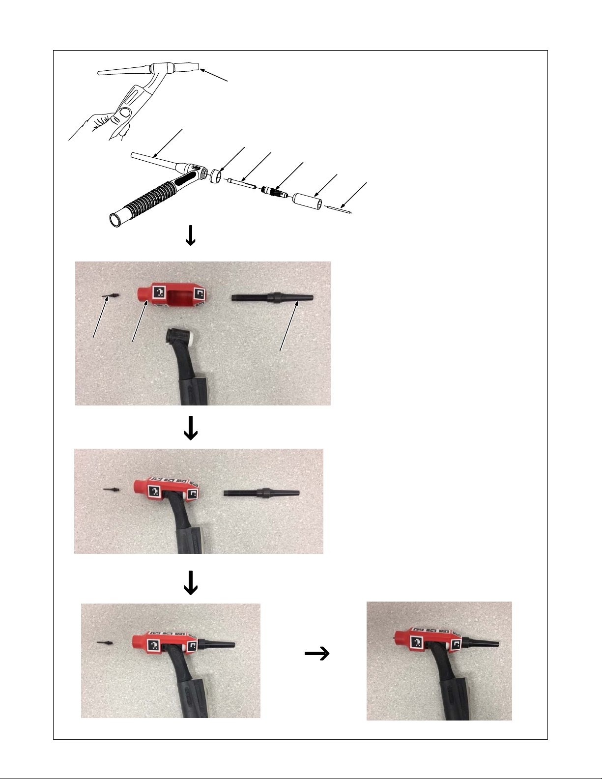
5-7. Assembling AR TIG Torch
2
9
8
1 AR TIG Torch
2 Backcap
1
7
6
4
3
5
10
3 Cup
4 Collet Body
5 Tungsten Electrode
6 Collet
7 Heat Shield
Remove backcap (counterclockwise).
The original backcap is not used
in the AR TIG torch assembly
and can be discarded.
Unscrew cup and collet body (counterclockwise).
Remove tungsten electrode and
collet.
Remove heat shield.
8 TIG Torch AR Nozzle
9 TIG Torch AR Tip
10 TIG Torch AR Backcap
Locate TIG torch AR nozzle, tip, and
backcap supplied with system.
Insert the head of the torch into the
opening of the AR nozzle. Insert the
AR backcap through the opening in
the rear of the AR nozzle and screw
into the TIG torch head (clockwise).
Screw the TIG torch AR tip into the
TIG torch AR nozzle (clockwise).
OM-278680 Page 11
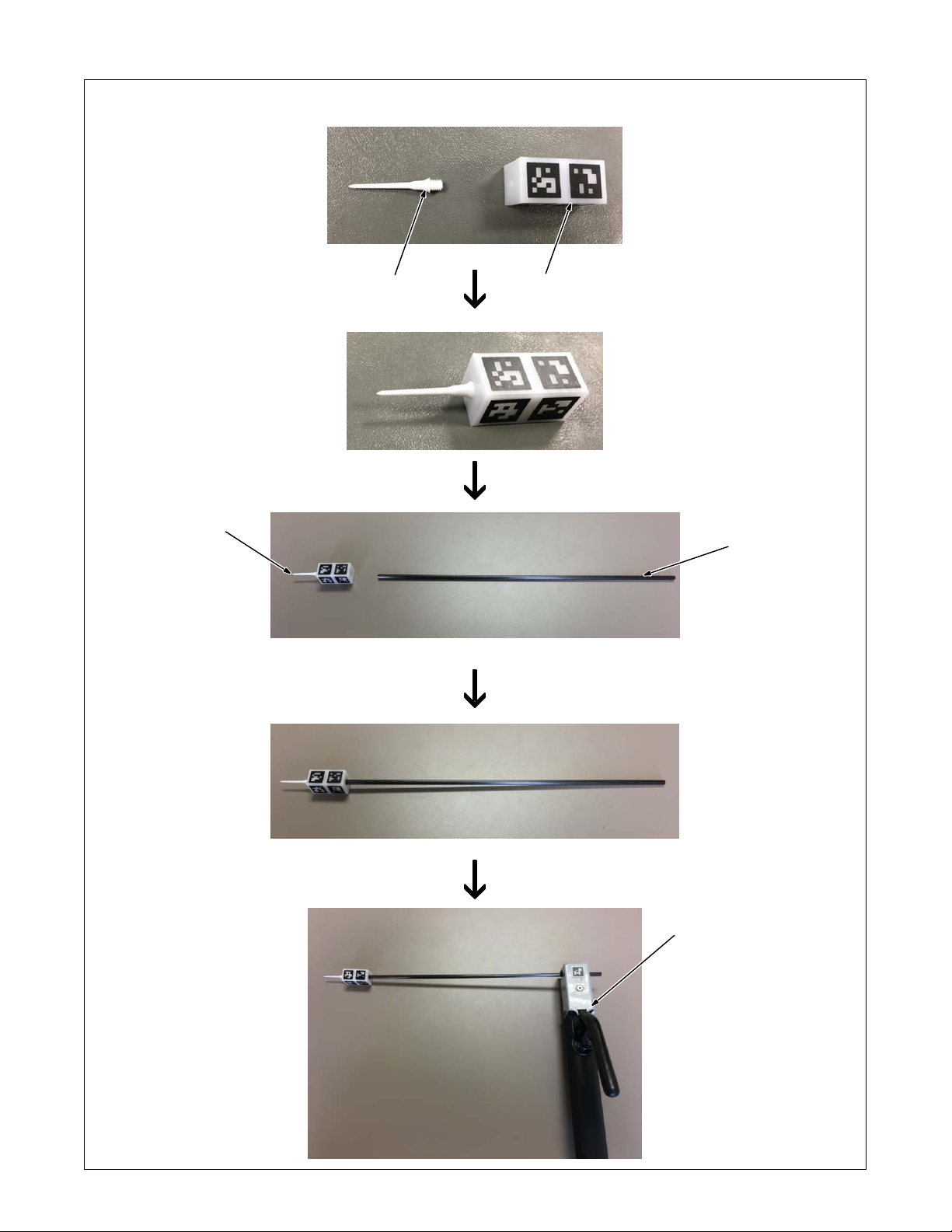
5-8. Assembling AR Stick Electrode
1
1 Marker Tip
2 Marker Block
Screw the marker tip into the
marker block.
3 Marker Assembly
4 Electrode
Press fit the marker assembly
over the tip of the electrode.
This assembly will also be
used as the TIG filler rod.
2
5 Electrode Holder
Place the stick electrode in the
electrode holder as shown. With
the handle facing up, the electrode
should face left.
3
5
4
OM-278680 Page 12
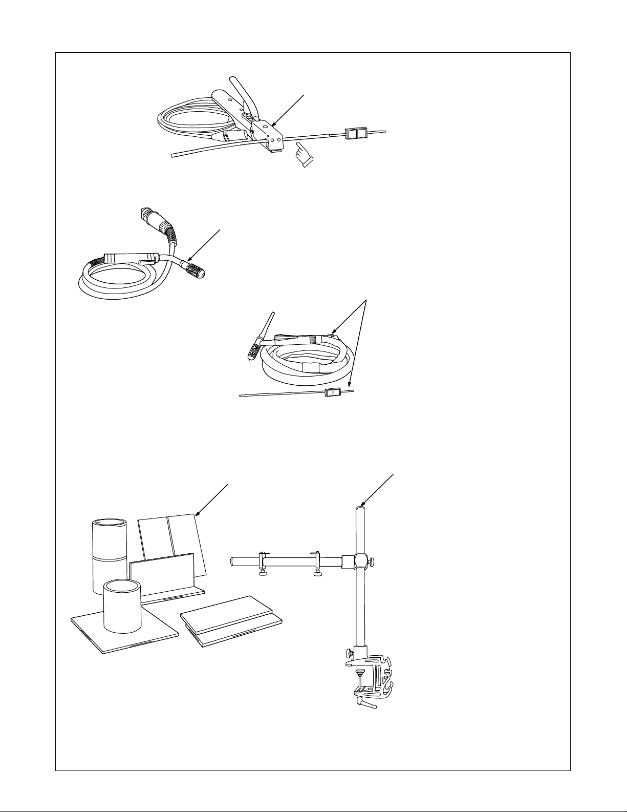
5-9. AR Stick Electrode, MIG Gun, TIG Torch, And Workpieces
1
Install Stick electrode in
holder exactly as shown.
2
3
5
4
1 AR Stick Electrode And Holder
Markers on the stick electrode allow it
to work with the AR system. The electrode is similar in shape, weight, and
size to a real electrode. It is placed
within the holder, which is connected to
the simulator. The holder retracts the
electrode during welding to simulate
the electrode consumption in real
welding.
2 AR MIG/FCAW Welding Gun
Markers on the AR MIG/FCAW welding gun allow it to work with the AR system. The gun is connected to a real
welding connector in the simulator.
MIG/FCAW welding is a semiautomatic process that uses a continuous wire
feed as an electrode and an inert (MIG)
gas mixture to protect the weld from
contamination.
(GMAW) or cored (FCAW). The stu-
dent begins by selecting the shielding
gas, wire type, and diameter. After the
exercise has begun, the student adjusts
the wire feed speed on the simulator.
3 AR TIG Torch And Filler Rod
Markers on the TIG (GTAW) torch and
AR filler rod allow it to work with the AR
system. The torch is connected to a real welding connector in the simulator.
The filler material is added to the weld
joint by a AR filler rod that is tracked using the AR marker accessory. The student adds filler by dipping the rod into
the weld joint, just as in real welding.
The AR filler rod is similar in shape,
size, and weight to a real filler rod and
helps the student become familiar with
using this equipment.
4 AR Workpieces
The AR workpieces are in standard
joint configurations (Bead On Plate,
T-Joint, Butt Joint, Lap Joint,
Pipe-Plate, Pipe-Pipe) and are designed to work with the AR system.
5 Workpiece Stand
Use to hold workpieces in position for
simulated flat, horizontal, vertical, or
overhead welding.
The wire can be solid
161-97
OM-278680 Page 13
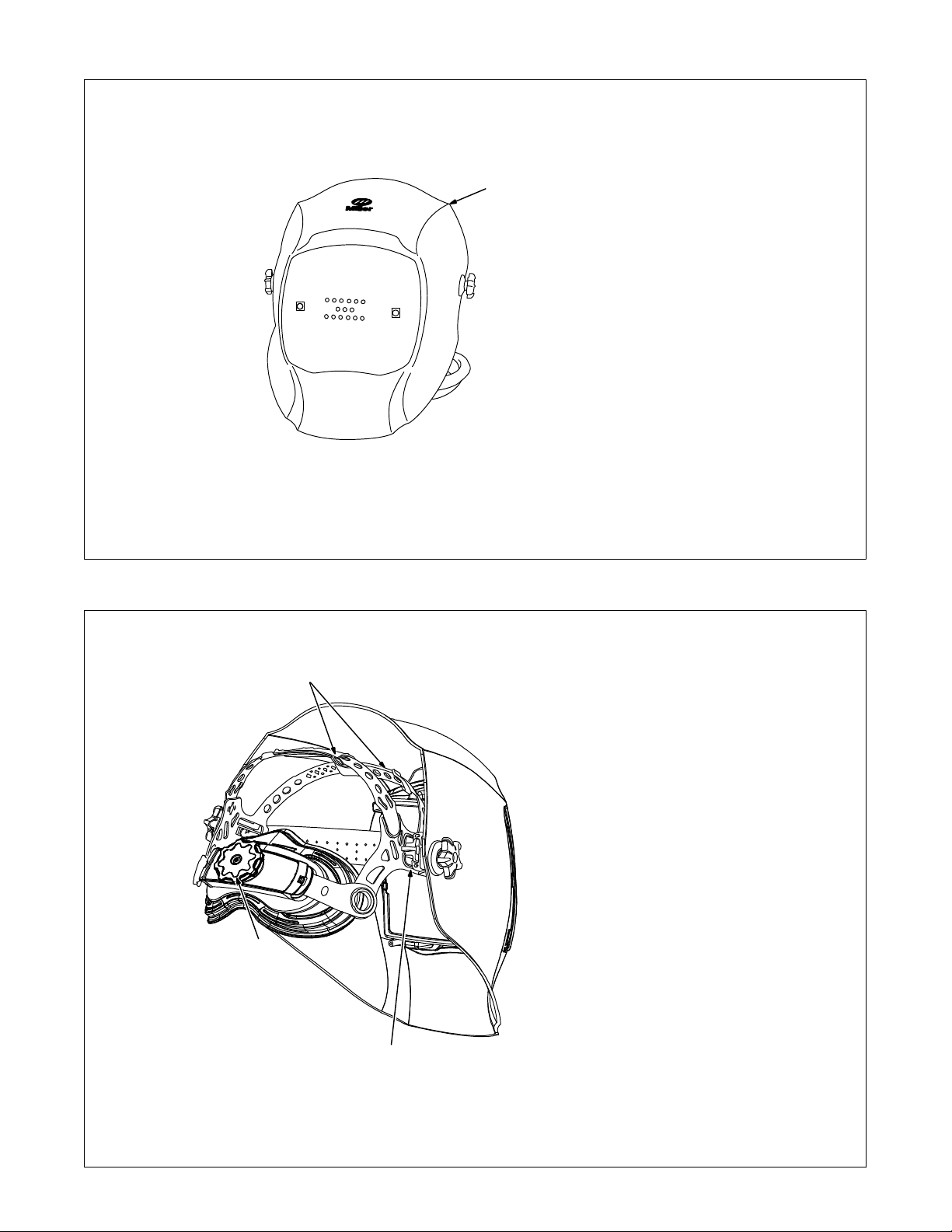
5-10. AR Welding Helmet
1 AR Welding Helmet
The AR welding helmet has two high
resolution micro-cameras and a 4.8 in.
(122 mm) display screen that enhances the augmented reality experience. The AugmentedArc acces-
1
sories (workpieces, guns, torches,
electrode, filler rod) and the real environment are displayed on the helmet
screen and these elements interact to
create a real-time augmented reality
for a realistic welding experience.
The AR welding helmet also includes
LED lights (controlled at the simulator)
to maintain the stable light environment necessary for the artificial vision
technology to work properly.
The AR welding helmet is also
equipped with speakers to recreate the
sounds emitted during the welding
process to make the training more authentic.
See Section 10 for information on
installing the optional magnifying
lens.
5-11. Making Helmet Adjustments
1
2
161-97
Helmet image is intended only for
reference in locating helmet adjustments.
There are four headgear adjust-
ments: headgear top, tightness,
angle, and distance.
1 Headgear Top
Adjusts headgear for proper depth on
the head to ensure correct balance and
stability.
2 Headgear Tightness
To adjust, turn the adjusting knob located on the back of the headgear left
or right to desired tightness.
3 Angle Adjustment (Not Shown)
Seven slots on the right side of the
headband provide adjustment for the
forward tilt of the helmet. To adjust, lift
and reposition the control arm to the
desired position.
4 Distance Adjustment
Adjusts the distance between the face
and the lens. To adjust, press black
tabs on the top and bottom of the pivot
4
point and use other hand to slide
headgear forward or backward. Release tabs. (Both sides must be equally positioned for proper vision.)
OM-278680 Page 14
Numbers on the adjustment slides
indicate set position so both sides
can be adjusted equally.
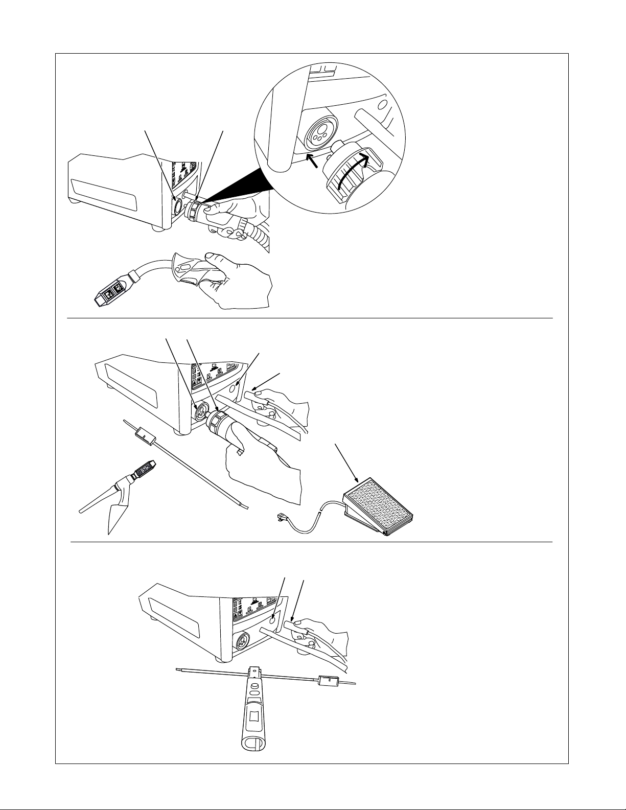
5-12. Connecting Weld Cables
2
1
MIG/FCAW Connections
1 MIG/FCAW Cable Connector
2 MIG/FCAW Receptacle
Align pins in connector with holes in receptacle. Insert connector in receptacle and tighten collar clockwise.
34
7
6
TIG Connections
3 TIG Cable Connector
4 TIG Cable Receptacle
Align pins in connector with holes in receptacle. Insert connector in receptacle
and tighten collar clockwise.
Optional Foot Pedal Kit Connections
TIG foot pedal and adapter cable are
included in optional TIG Foot Pedal
5
9
8
Kit.
5 TIG Foot Pedal
6 Adapter Cable
7 TIG Foot Pedal Receptacle
Insert foot pedal connector (RJ-45) into
adapter cable receptacle. Insert adapter
cable connector into TIG foot pedal receptacle on simulator.
Stick Connections
8 Stick Cable Connector
9 Stick Cable Receptacle
Align pins in connector with holes in
receptacle. Insert connector in receptacle.
161-103 / 104 / 105 / 106
OM-278680 Page 15
SECTION 6 − SYSTEM CONTROLS AND COMPONENTS
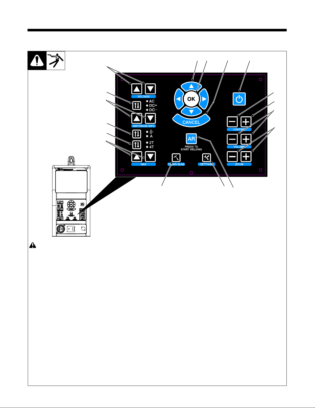
6-1. Simulator Controls
14
13
12
11
10
15
16 17
9
678
1
2
3
4
5
! Do not use the welding simulator if
you are light sensitive or affected by
video, flashing lights, or other visual
stimuli. Stop using simulator and
consult your physician if you experience vision problems, nausea,
headaches,
other conditions.
dizziness, vertigo, or
For best performance, keep helmet,
guns, torches, and workpieces free of
dust and debris. Clean components
with a damp cloth. (Do not use chemicals, solvents, or abrasives to clean
markers.)
1 Power On/Off Button
Use button to turn system on and off.
2 Helmet Light Intensity Decrease
Button
Use button to decrease intensity of helmet
light.
3 Helmet Light Intensity Increase Button
Use button to increase intensity of helmet
light.
4 Volume Adjustment Buttons
Use buttons to increase or decrease volume of helmet speakers
5 Display (Zoom) Adjustment Buttons
Use buttons to magnify images on display
screens.
6 Augmented Reality (AR) Button
Use button to turn augmented reality feature
on and off.
7 System Settings Button
Use button to access system settings
menu. Use the settings menu to change language, units of measure (standard or metric), camera settings and other parameters.
After starting an exercise, use the System
Settings button to adjust video device settings and optimize AR tracking for the room
lighting conditions (see Section 8-7).
Some settings can only be changed by
the system administrator.
8 Clean Slag Button
Use button to remove slag from augmented
reality workpiece when Stick and FCAW
welding. Slag must be cleaned for test results to be displayed.
9 Shielding Gas Flow Adjustment
Buttons
Use buttons to increase or decrease the
shielding gas flow for the GMAW, FCAW,
and GTAW weld processes.
Ref. 276687-A
10 Gun Trigger Selection Button
Use button to select either two-step or
four-step trigger operation.
11 Amperage/Wire Feed Speed
Selection Button
Use button to select the weld parameter
(amperage or wire feed speed) to be adjusted (see Item 12).
12 Amperage/Wire Feed Speed
Adjustment Buttons
Use buttons to increase or decrease amperage or wire feed speed (see item 11).
13 AC/Polarity Selection Button
Use button to select AC weld output or
DCEP or DCEN weld polarity.
14 Voltage Adjustment Buttons
Use buttons to increase or decrease weld
voltage.
15 System Navigation Buttons
Use buttons to navigate AR system pro-
grams and select menu items.
16 OK (System Selection) Button
Use button to activate selected menu items.
17 System Cancel Button
Use button to stop the AR program or activi-
ty in use, or return to the previous screen.
OM-278680 Page 16
SECTION 7 − OPERATION
Do not use the welding simulator if you are light sensitive or affected by video, flashing lights, or other visual stimuli. Stop using simulator and consult your physician if you experience vision problems, nausea, headaches, dizziness, vertigo, or other conditions.
A MIG/FCAW welding simulation is shown in these examples. Setup and adjustments are similar for other welding processes.
7-1. Equipment Setup
• Assemble AugmentedArc training system. Install system in proper location and near 120 volt AC power source (see Section 5-1).
• Connect desired gun or torch to simulator (see Sections 5-9 and 5-12).
• Connect simulator and router power cords to 120 volt AC receptacles.
• Place simulator Input Power switch in On position (on back of simulator). Press router Power switch. Press and hold On-Off switch on front of
simulator until simulator turns on. For Classroom applications, also place controller Input Power switch (on back panel) in On position (see Section
5-4). Press and hold controller Power On/Off switch (on front panel) until unit turns on.
7-2. Getting Started
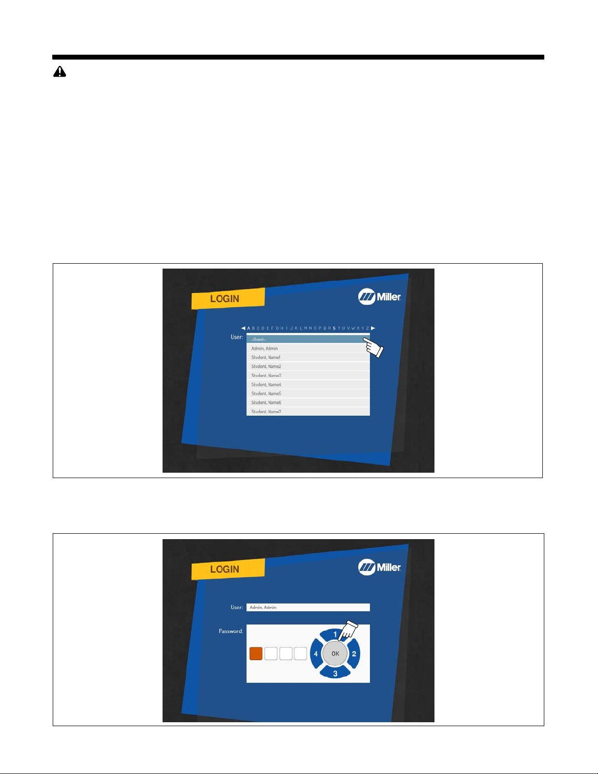
A. Login Screens
Use System Navigation buttons to select guest or user name from Login menu. Press OK.
To create a new user, see Section 9, Using The Teacher Software.
Figure 7-1. User Selection Screen
Use System Navigation buttons to enter User password. Each button represents a specific numeral (1 − 4) as shown in Figure 7-2. (The default
Admin user password is 1111.) Press OK.
Passwords are established by the instructor. Guest users do not need a password.
The default Admin user
password is 1111.
Figure 7-2. Password Screen
OM-278680 Page 17
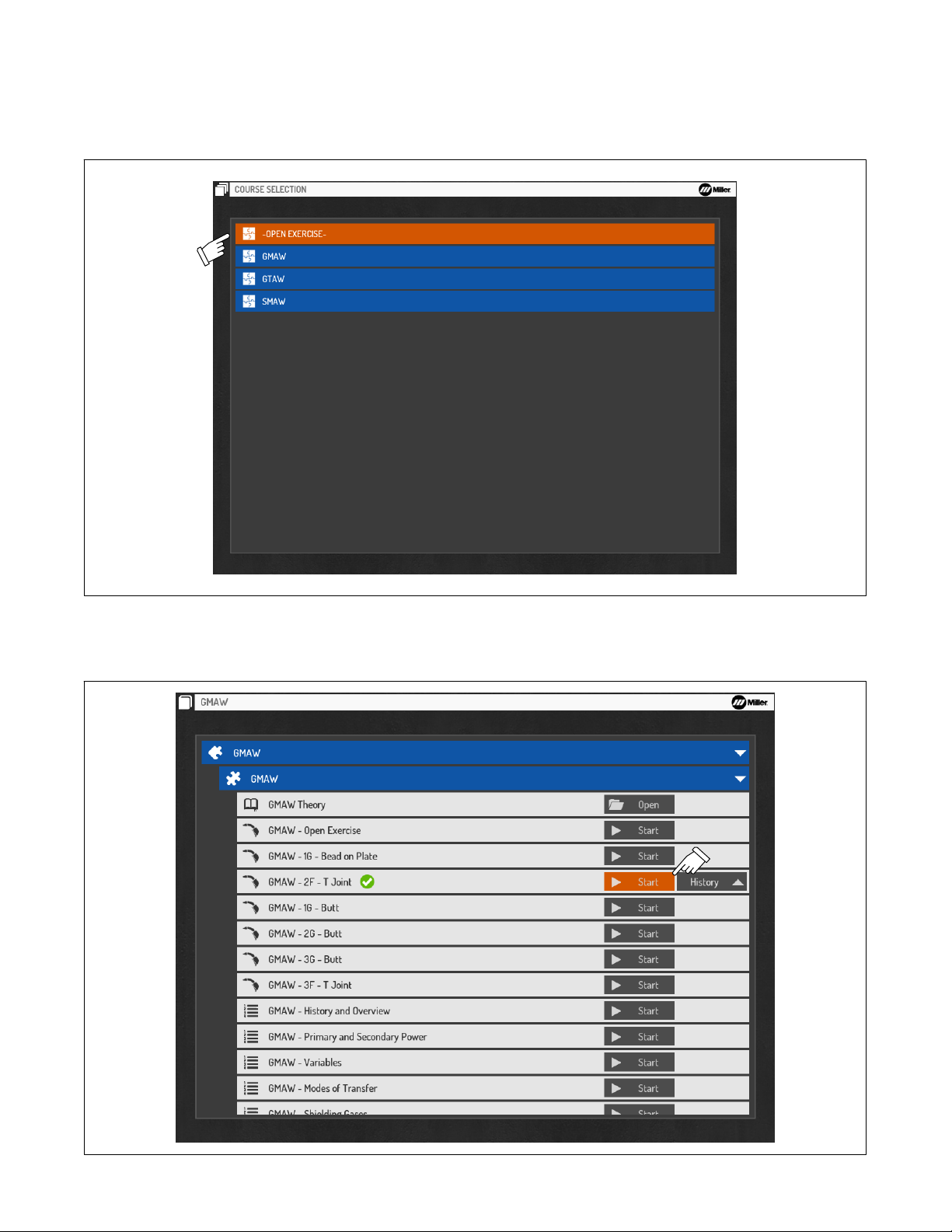
B. Course Selection
Use System Navigation buttons to select desired course (Figure 7-3). Press OK.
Course selection will vary for each user.
Press the Cancel button at any time to stop the program and return to the previous screen.
Figure 7-3. Course Selection Screen
Use Navigation buttons to select (Start) a new exercise session or review previous sessions (under the History tab). See Figure 7-4. Press OK.
The History feature is not available to Guest users.
OM-278680 Page 18
Figure 7-4. Activity Selection Screen
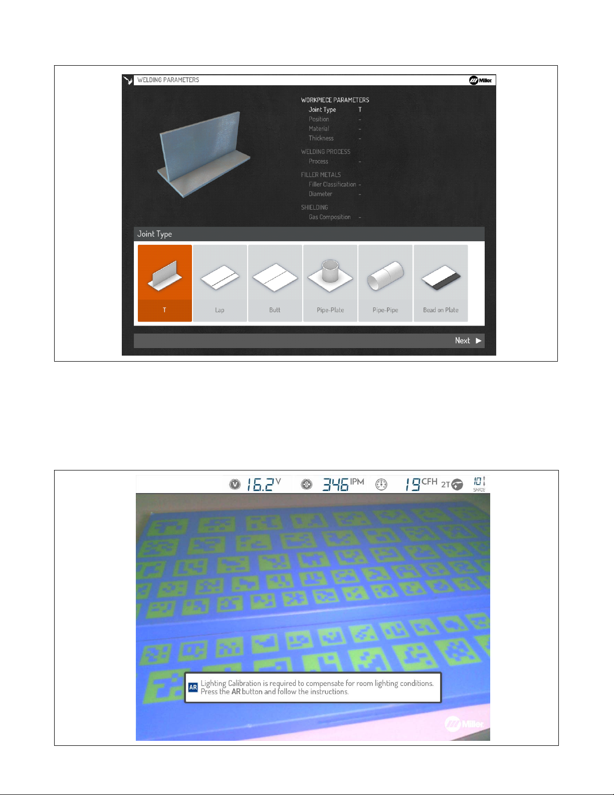
Use Navigation buttons to select or acknowledge the difficulty level (Beginner, Intermediate, Advanced), joint type, position, material
type/thickness, weld process, electrode type/diameter, gas composition, and other parameters as applicable (Figure 7-5).
Figure 7-5. Welding Parameters Screen
C. Lighting Calibration
Depending on the selected Lighting Calibration option for the system (see Section 8-2F), the user may be prompted to perform a lighting
calibration procedure before starting the exercise. The lighting calibration will adjust the video device settings (temperature, intensity) based on
the room lighting conditions.
Ensure helmet illumination is turned on (see Section 6-1).
Press the AR button to begin the process.
Figure 7-6. Lighting Calibration Screen
OM-278680 Page 19
 Loading...