

The Arrow Series Fluid Head Operator’s Manual
#1020 Arrow 30 with Euro camera platform
#1012 Arrow with Euro camera platform
#1014 Arrow HD with Euro camera platform
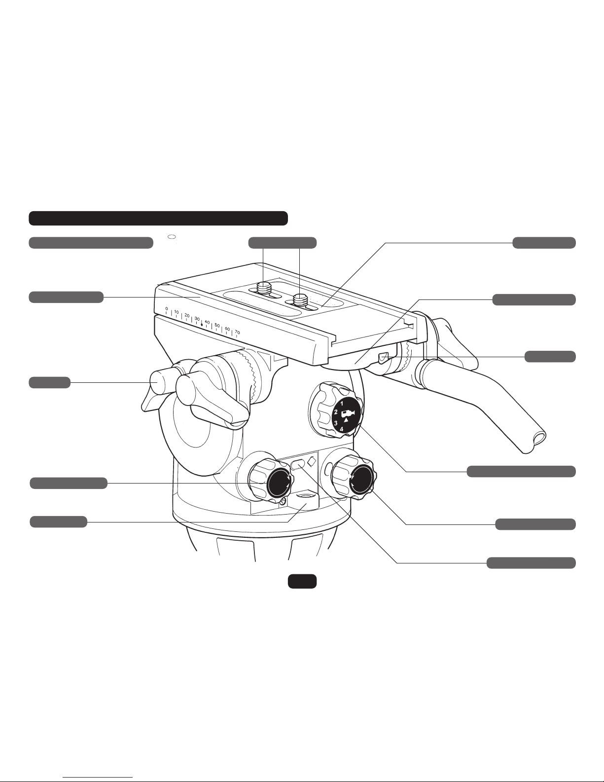
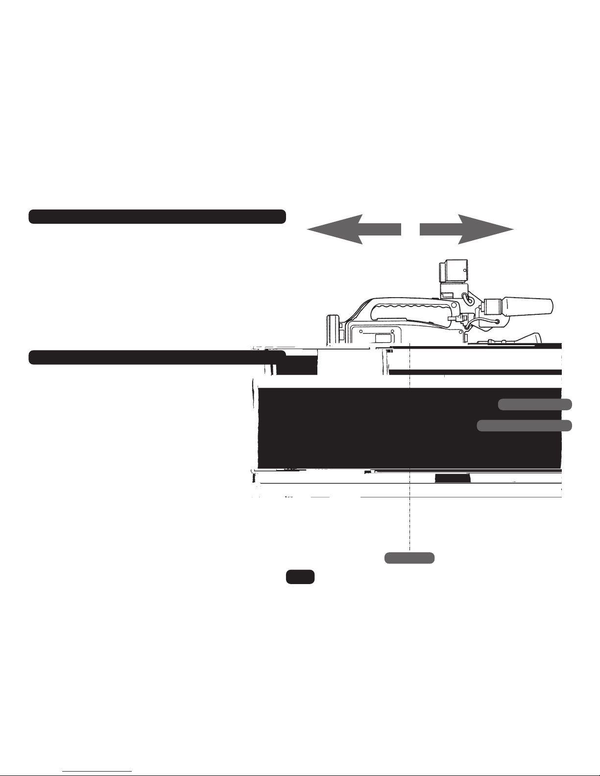
SLIDING PLATFORM
Arrow 30 and Arrow - 70mm range
Arrow HD - 100mm range
Arrow 30 only
CAMERA SCREWS1/4” AND PIN ADAPTOR CARRIAGE CAMERA PLATE
QUICK RELEASE LEVER
SAFETY TAB
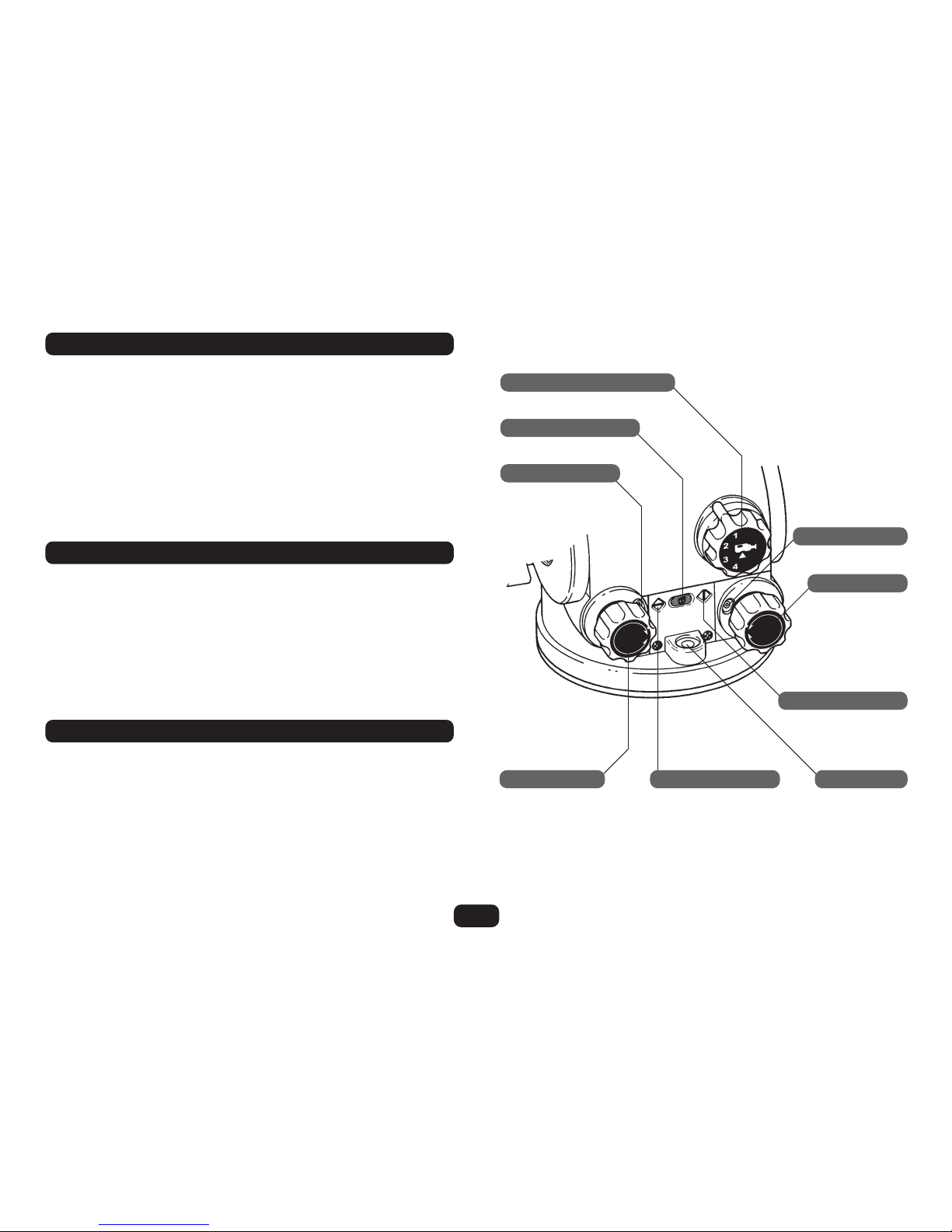
COUNTERBALANCE SELECTOR
PAN DRAG CONTROL
ILLUMINATION BUTTON
TILT LOCK
TILT DRAG CONTROL
BUBBLE LEVEL
FEATURES AND CONTROLS
2
FIG 1
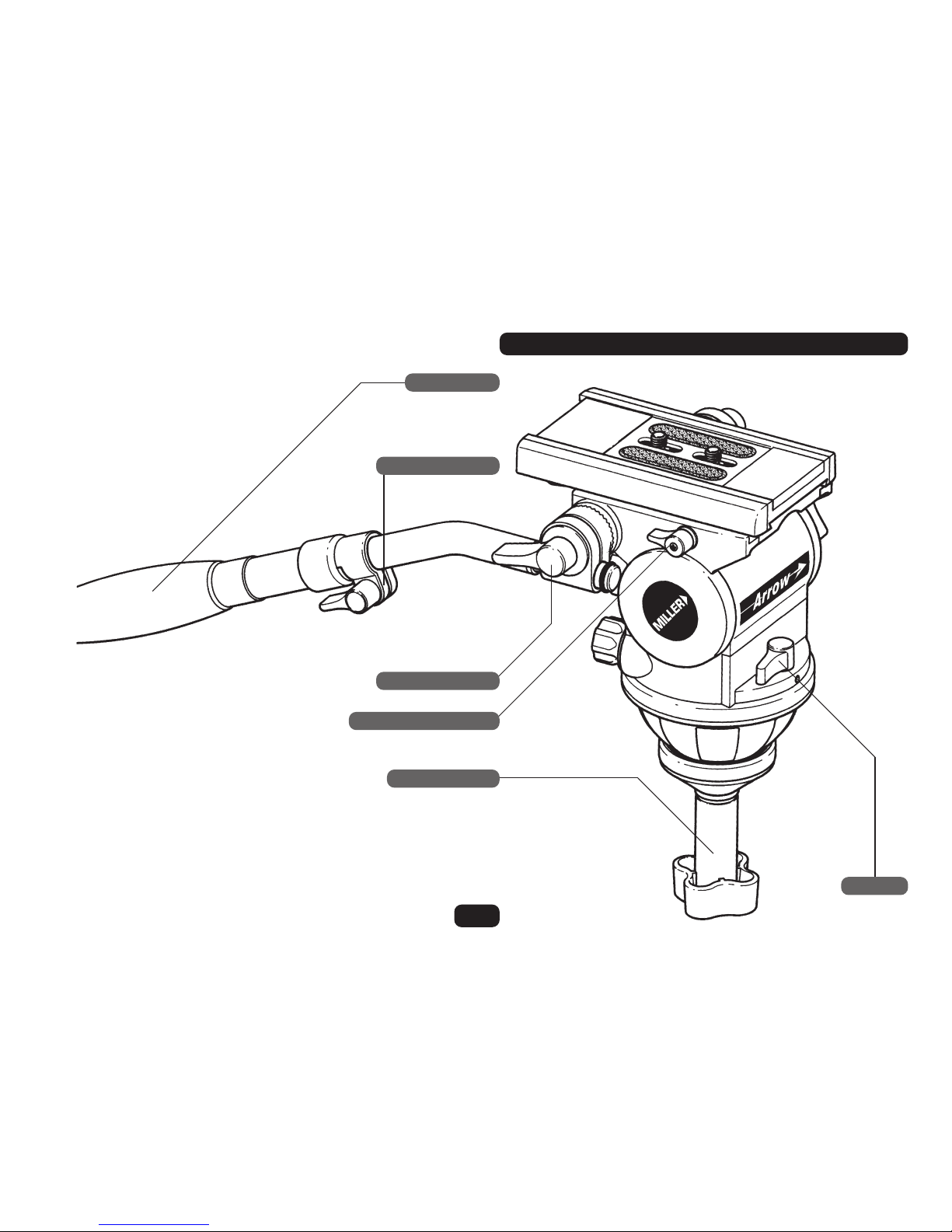
FEATURES AND CONTROLS
3
FIG 2
PAN HANDLE
TELESCOPIC CLAMP
PAN HANDLE CLAMP
SLIDING PLATFORM LOCK
BOWL CLAMP NUT
PAN LOCK
SAFETY INSTRUCTIONSCONTENTS
4
FEATURES AND CONTROLS 2 and 3
SAFETY INSTRUCTIONS 4
INTRODUCTION 4
TECHNICAL DATA 5
OPERATING INSTRUCTIONS 6
1. Install and level the Head 6
2. Mount Your Camera 7
3. Centre Your Camera on the Head 8
4. Counterbalance Your Camera 9
5. Drag Control 10
6. Illumination 10
MAINTENANCE 10
7. Battery Replacement 11
CLEANING 11
STORAGE Back Cover
SPARE PARTS AND ACCESSORIES Back Cover
WARRANTY Back Cover
SERVICE Back Cover
Before operation read the Operating Instructions (pp6-12).
Arrow fluid heads have been designed to accommodate film
and television cameras, and to be operated by qualified
camera operators.
Hold camera securely during all fitting or removal operations.
Do not adjust the counterbalance or drag settings without
securing (holding) pan handle.
To prevent accidental or sudden movement do not release the
TILT LOCK without holding the PAN HANDLE.
Do not release the clamp nut without holding either the head
or attached camera.
Do not exceed the maximum total payload (see Technical
Specifications).
The operator is responsible for the safe operation of this piece
of equipment.
Welcome to the Operating Manual for the Arrow 30, Arrow and
Arrow HD fluid head. Arrow is a versatile fluid pan/tilt head
designed for a wide variety of cameras and configurations.
Developed using the latest 3D modelling software and
manufactured with computer-controlled precision, Arrow is
designed to reliably and stably support portable film and video
cameras shooting in the world’s most challenging conditions.
From lightweight ENG camcorders to heavier EFP dockable
cameras, Arrow heads offer optimum lightweight, robust
performance with the smoothest fluid motion - from the
company that invented and patented the fluid head.
INTRODUCTION

DATA Arrow 30 Arrow Arrow HD
5
WEIGHT 3.2kg 3.2kg 3.3kg
MAX REC. LOAD 15kg (see graph on Page 9) 20kg (see graph on Page 9) 25kg (see graph on Page 9)
BALL LEVELLING BASE 100mm 100mm 100mm
PAN MECHANISM Stepped Fluid Drag Stepped Fluid Drag Stepped Fluid Drag
Adjustment 7 selectable positions + zero 7 selectable positions + zero 7 selectable positions + zero
Rotation 360º 360º 360º
Lock Calliper disc brake system Calliper disc brake system Calliper disc brake system
TILT MECHANISM Stepped Fluid Drag Stepped Fluid Drag Stepped Fluid Drag
Adjustment 7 selectable positions + zero 7 selectable positions + zero 7 selectable positions + zero
Tilt Angle
+
_ 90º
+
_ 90º
+
_ 90º
Lock Calliper disc brake system Calliper disc brake system Calliper disc brake system
COUNTERBALANCE 4 selectable positions 4 selectable positions 4 selectable positions
CAMERA PLATFORM Euro quick release camera plate in Euro quick release camera plate in Euro quick release camera plate in
sliding camera balance platform sliding camera balance platform sliding camera balance platform
Camera Attachment
3/8”+ 1/4” screws + 1/4” pin carriage 3/8”+ 1/4” screws 3/8”+ 1/4” screws
Sliding Range 70mm (+/-35mm) 70mm (+/-35mm) 100mm (+/-50mm)
LEVELLING
Illuminated bubble level: 10 sec auto-off Illuminated bubble level: 10 sec auto-off Illuminated bubble level: 10 sec auto-off
PAN HANDLE Telescopic (220mm extension range) Telescopic (220mm extension range) Telescopic (220mm extension range)
ILLUMINATED CONTROLS
Bubble level, pan/tilt number Bubble level, pan/tilt number Bubble level, pan/tilt number
TEMP. RANGE –40ºC to +65ºC – 40ºC to +65ºC – 40ºC to +65ºC

OPERATING INSTRUCTIONS
6
The Operating Instructions for Arrow series fluid heads are
described in six (6) steps. Please read and understand these
instructions before using this equipment. Do not omit any
step.
1.1 Unscrew the CLAMP NUT from its threaded stud.
1.2 Place the head in your 100mm tripod bowl and re-fit the
CLAMP NUT. Do not tighten CLAMP NUT.
1.3 Level the fluid head by centering the bubble in the
BUBBLE LEVEL. Then tighten the CLAMP NUT.
1.4 In low light conditions the BUBBLE LEVEL can be
illuminated by pressing the ILLUMINATION BUTTON.
1.5 Note: If adjusting the level with your camera mounted,
first ensure the camera is securely held before loosening
CLAMP NUT.
1 INSTALL AND LEVEL THE HEAD
ILLUMINATION BUTTON
BUBBLE LEVEL
TRIPOD BOWL
THREADED STUD
CLAMP NUT
FIG 3

2 MOUNT YOUR CAMERA
7
Arrow is equipped with a sliding platform for balance fine
tuning, plus a quick-release camera plate and standard camera
mounting screws (Arrow and Arrow 30 have 70mm sliding
range, Arrow HD has 100mm sliding range). Please note that
best camera control can be achieved by balancing the camera
centre of gravity (C of G) over the centre axis of the head.
2.1 Lock the PAN and TILT LOCKS (rotate both levers clockwise
until firm).
2.2 Remove the CAMERA PLATE by pulling downwards on the
SAFETY TAB while rotating the QUICK RELEASE to the left
until it reaches the automatic stop position (the CAMERA
PLATE will pop up).
2.3 With accessories and battery fitted, determine your
camera’s C of G by the best method available (Eg: balance
the camera on a rod or similar to find balance point).
2.4 Attach the CAMERA PLATE over the C of G by fastening
the 3/8” + 1/4” CAMERA SCREWS into your camera’s base
or ‘tripod adaptor plate’. These screws should be
tightened evenly and as far apart as possible to prevent
any movement between your camera and the fluid head.
N.B. Arrow 30 is also supplied with a 1/4” screw & pin
carriage (Cat#493) for direct attachment to MiniDV
camcorders which do not require a tripod adaptor plate.
When attaching the camera carriage to a camcorder,
ensure the carriage’s locating pin fits comfortably into the
camcorder socket, then screw the 1/4” screw clockwise
until the camera plate is attached firmly to the camcorder.
Warning: If the carriage pin does not easily fit into the
camcorder socket, DO NOT force it. Contact Miller or your
nearest authorised dealer for specific advice relating to
your camcorder model.
FIG 4
CAMERA PLATE
SLIDING PLATFORM
CENTRE AXIS
2 MOUNT YOUR CAMERA Continued
8
2.5 Attach your camera to the fluid head by holding your
camera slightly ‘lens down’ and place the attached
CAMERA PLATE under the front lip on the top of the
SLIDING PLATFORM. Lower the back of the camera until
the QUICK RELEASE snaps automatically to the locked
position. Ensure the QUICK RELEASE knob is firmly seated.
2.6 To ensure a successful mount, grip the PAN HANDLE firmly
and then disengage the PAN and TILT LOCKS. Your camera
should be firmly attached with no obvious free movement.
SLIDING PLATFORM
SLIDING PLATFORM LOCK
CENTRE AXIS
FIG 5
3 CENTRE YOUR CAMERA ON THE HEAD
3.1 With your camera attached to the fluid head, hold the PAN
HANDLE and release the TILT LOCK.
3.2 Turn the TILT DRAG CONTROL knob to position ‘0’. Turn
the COUNTERBALANCE SELECTOR knob to position ‘1’.
3.3 Release the SLIDE LOCK lever and slide your camera
forward or backward until balanced over the centre axis of
fluid head. If necessary, be prepared to stop your
camera sliding suddenly. Your camera will remain
static when balanced.
3.4 Re-engage the SLIDE LOCK and TILT LOCK by
turning clockwise until firm.

4 COUNTERBALANCE YOUR CAMERA
9
The Arrow 30, Arrow and Arrow HD include a variable
counterbalance system that provides fingertip control through
its tilt range and allows the camera to be set at any angle
within that range. The counterbalance control can be set in
one of four (4) positions depending on your camera payload.
4.1 Hold the PAN HANDLE and release the TILT LOCK.
4.2 Rotate the counterbalance control knob to setting ‘1’ or ‘2’
for light payloads, ‘3’ or ‘4’ for heavy or off-set payloads.
4.3 Tilt the camera through its tilt range. Loosen hold on the
PAN HANDLE to check that your camera remains static in a
tilted position. If the camera moves from its tilted position,
return the camera to the horizontal position and turn the
COUNTERBALANCE SELECTOR knob to a higher or lower
setting. Tilt through the range again and repeat this test
until the camera remains static in both tilted forward and
tilted backward positions.
Note: If accessories are added or removed, re-balance can be
achieved by adjusting the COUNTERBALANCE SELECTOR,
and/or adjusting the SLIDING PLATFORM position, or by repositioning the CAMERA PLATE on your camera’s base or
‘tripod base plate’.
250
200
150
100
50
0
Centre of Gravity (mm)
Camera Payload (kg)
024 6 8101214161820222426024 6 81012141618202224024 6 81012141618
Counterbalance data;
Arrow 30 Arrow Arrow HD
COUNTERBALANCE SELECTOR
ILLUMINATION BUTTON
TILT DRAG SETTING
FIG 6
5 DRAG CONTROL
6 ILLUMINATION
MAINTENANCE
10
5.1 Arrow heads provide seven (7) incremental settings for tilt
and pan drag control as well as a zero (0) freewheeling
position. There are no half stops. When changing drag
settings, pan and tilt movements must be stopped. There
is an endstop between Position 7 and Zero. This eliminates
the risk of moving the control clockwise from ‘7’ to ‘0’ and
the potential risk of the payload falling forward.
5.2 To achieve smooth diagonal movement, ensure that tilt
and pan drag controls are on similar settings.
For low light conditions, Arrow heads provide illumination of
the bubble level, the pan and tilt drag settings and pan and
tilt knob indicators.
6.1 Press the ILLUMINATION BUTTON to illuminate these
features. You do not need to hold it down. All the above
features will remain illuminated for 10 seconds, then will
switch OFF automatically.
With the exception of external surface cleaning and battery
replacement, Arrow heads do not require additional
maintenance.
Miller Authorised Service Agents must carry out all service and
repair work. Failure to observe this requirement may void
warranty.
PAN DRAG SETTING
PAN DRAG KNOB
PAN KNOB INDICATOR
BUBBLE LEVELTILT KNOB INDICATORTILT DRAG KNOB

7 BATTERY REPLACEMENT
CLEANING
11
The Arrow illumination feature uses a standard long–life
alkaline 12v battery. Under most operating conditions the
battery will provide two years of operation.
Miller approves use of the following batteries: Duracell MN21,
Eveready A23, Vinnic L 1028. Other GP23A batteries also fit.
To change the BATTERY:
7.1 Unscrew the two battery door RETAINING SCREWS and
remove the BATTERY DOOR.
7.2 Remove the BATTERY.
7.3 Insert a new battery, negative end (-) first
7.4 Replace BATTERY DOOR and RETAINING SCREWS.
7.5 Press the ILLUMINATION BUTTON to test operation.
WARNING: Do not immerse in any liquid.
WARNING: Do not use stiff brushes, abrasives, or solvents.
Arrow heads feature protective coatings, dust and moisture
seals and anti-corrosive fittings to ensure long and trouble free
operation, even in harsh environments. To ensure optimum
performance through the life of the head Miller recommends
basic routine maintenance.
When Arrow heads have been used in harsh environments
(such as sand, mud or salt water spray), wipe over with a soft
damp cloth as soon as possible. Use a soft brush to clean
crevices. Remove and clean CAMERA PLATE.
FIG 7
ILLUMINATION BUTTON
BATTERY
BATTERY DOOR RETAINING SCREW

SERVICE, SALES AND SUPPORT
WEB SITE www.millertripods.com
STORAGE
SPARE PARTS AND ACCESSORIES
WARRANTY
When storing your Arrow for extended periods: remove
BATTERY, clean fluid head, and place in a safe, dry place, away
from direct sunlight. Arrow heads can be stored horizontally or
upright. However, it is not advisable to store the head for
extended periods with the tilt locked in an extreme position,
either forward or backward.
ITEM ITEM NO.
Battery P3798
Euro camera plate 79 x 64.5mm (3/8” + 1/4” screws) #860
Camera screw 3/8”W P0037
Camera screw 1/4”W P0036
1/4” + pin camera carriage #493
Telescopic Pan Handle with clamp #694
Telescopic Pan Handle #692
Pan handle - Telescopic with handle clamp #684
Clamp nut P3836
Flat Base adaptor #360
Miller Authorised Service Agents must carry out all service and
repair work. Failure to observe this requirement may void
warranty. It is advisable to notify Miller or a Miller Authorised
Service Agent if a change of performance is observed as a
result of dropping or rough usage. For information regarding
sales and service of Miller products, or for your nearest Miller
representative please contact us via our website or at the
following:
MILLER CAMERA SUPPORT EQUIPMENT
30 Hotham Parade, Artarmon, Sydney,
NSW 2064 Australia
Tel: +61 2 9439 6377
Fax: +61 2 9438 2819
Email: sales@miller.com.au
MILLER FLUID HEADS (EUROPE) LTD.
Unit A2, Ford Lane Industrial Estate
Ford Lane, Ford
West Sussex BN18 0DF, United Kingdom
Tel: +44 (0)1243 555255 Fax: +44 (0)1243 555 001
Email: sales@millertripods-europe.com
MILLER Camera Support (LLC) USA
216 Little Falls Road, Cedar Grove,
New Jersey 07009-1231 USA
Tel: (973) 857 8300
Fax: (973) 857 8188
Email: sales@millertripods.us
MILLER TRIPODS Canada
1055 Granville Street
Vancouver BC V6Z1L4, Canada
Tel: (604) 685 4654
Fax: (604) 685 5648
Email: sales@millercanada.com
Please refer to warranty card for complete details.
3994-5 05/06
 Loading...