

Miller ANALOG 300 Owner's Manual
August
1975
Effective
with
serial
FORM:
No.
OM-215A
HF859183
FILE
RETURN
COPY
TO
FOLDER
MODEL
W/ELECTROSLOPE
W/PULSER
W/ELECTROSLOPE
ANALOG
&
300
PULSER
STOCK
901
901
901
NO.
408
410
417
ADDITIONAL
PRICE
$1.10
COPY
MODEL/STOCK
NO.
OWNERS
MILLER
APPLETON,
SERIAL/STYLE
NO.
ELECTRIC
WISCONSIN,
CODE
NWSA
DATE
PURCHASED
MANUAL
CO.
54911
NO.
MFG.
USA
4579
~!jto
c
C
C)
C
c
I
C
C3
C
Q
QW
~OTbb
~
~
~
0
W
WJ
oTbT~O
oTbTO
MILLER
material
and
operated
MILLER
or
correcting
part
tion
confirms
Appleton,
portation
Q
Q
QW
~T~Th
Electric
factory
according
Electric
costs
the
Wisconsin
of
Mfg.
existence
any
Q
W~J
Co.,
Mfg.
workmanship
manufacturers
to
Co.s
manufacturing
any
f.o.b.aMILLER
or
will
kind
Q
QILQ
Q Q QQQQQQ Q
b
WARRANTY
Appleton,
for
instructions.
obligation,
of
such
be
allowed.
defect
defects.
Wisconsin,
the
periods
this
under
without
MILLERS
authorized
0
Q~Q
QIQ
warrants
indicated
warranty,
charge
option
service
Qi
LtQJQ
all
below,
is
during
of
facility,
tQJtQQLQJtQtQJJJkQJJ
TbThbTh
new
equipment
provided
limited
to
replacingorrepairing
the
warranty
repairorreplacement
and
therefore
bT~ThTbTbT~ThTTb~W
free
to
the
equipment
period
no
be
compensation
will
if
MILLERS
be
from
f.o.b.
is
installed
any
Q1.LQJ
defects
and
defective
inspec
factory
for
trans
in
at
QLWJ
~
C
C
C
~
C
C
~
C
The
follows:
Engine
through
accessories,
MILLER
directlyorindirectly
This
warranties
RHS-2
(Stock
Momentary
for
triggering
RHC-3-1010
Remote
prong
warranty
Warranties
their
Electric
warranty
No.
contact
(Stock
hand
twistlock
period,
beginning
1.
2.
3.
4.
5.
6.
are
Arc
Original
MHFC-L1
and
All
Mag-Diesel
All
covered
authorized
such
being
Mfg.
from
subject
Co.
supersedes
or
expressed
implied.
~*+~+~
040
048)
(normally
040
Furnished
832)
control
Electroslopes.
No.
amperage
plug.
welders,
all
guns
other
other
Service
local
to
will
the
use
all
previous
open)
with
the
on
power
main
power
Feeder,
and
Millermatic
engine
engines
the
by
engine
the
warranties
be
not
of
equipment
switch.
with
10
dateofsale
sources,
rectifiers
MHG-35C1,
torches
Feeders
DEL-200
on
manufacturers,
Stations
MILLER
liable
or
of
for
~+
Attaches
cord
28
direct
turn
the
to
and
components
20E,
agencies.
their
any
covered
warranties
the
to
and
twistlock
reading
original
purchaser-user
20K,
subject
No
warranty
respective
loss
or
in
consequential
this
warranty.
is
and
TIG
torch
plug.
(in
amperes)
1
3
90
1
6
1
their
to
will
manufacturers.
exclusive
handle.
Used
digital
of
the
equipment,
year
(unconditionally)
years
day~
ye~r
months
year
made
no
for
on-off
Furnished
and
in
or
other
procedures
be
damage
with
dial.
to
respect
expense
guarantees
control
will
handled
be
to
accruing
with
be
trade
of
20
as
or
contactor
cord
and
c
or
3
RFS-2
Maintained
Furnished
RFCE-31
Remote
twistlock
No.
3
Three
water
(Stock
(Stock
foot
Running
pneumatic
coolant
No.
with
cap
contact
No.
amperage
anda3
Gear
system.
040
28
(Stock
rubber
064)
foot
cord
040
conductor
operated
twistlock
and
666)
and
contactor
No.
tired
switch.
cord
040
wheels
Can
plug.
control,
terminates
016)
16
be
diameter
in
converted
1000
ina3
ohm.
prong
with
to
a
Two
twistlock
towing
momentary
cords.A2
20
cap.
handle.
type.
Will
Used
conductor
carry
on-off
for
cord
welder,
control
terminates
two
gas
of
contactor.
in
2
a
prong
cylinders
and
CERTI
FICATE
NAME
SERIAL
by
late
the
OF
NO.
This
Joint
less
established
Installations
meet
the
stalled,
structions
only
ance
Date
operated
The
welding
the
for
with
lnstallet
EQUIPMENT:_______________________
_____________________________
has
equipment
Industry
than
10
the
by
using
radiation
and
been
Committee
microvolts
Federal
this
limitations
maintained
type-tested
on
High
meter
per
Communications
equipment
established
as
specified
on
USERS
equipment
applicable
purpose
the
manufacturers
to
for
this
which
identified
model
instructions.
above
outlined
as
it
was
intended
under
Frequency
distance
at
a
Commission
the
basis
the
by
in
CERTIFICATION
has
DATF
standardized
Stabilized
of
of
these
Federal
the
instruction
installed
been
the
in
and
instruction
is
being
MODEL
field
test
Arc
Welding
one
mile,
for
equipment
tests,
may
Communications
book
accordance
in
book
maintained
NO.,________________
conditions
the
maximum
of
Machines
this
as
type.
recommended
found
allowable
reasonablybeexpected
Commission,
only
provided.
with
the
specific
It
furnished.
and
is
operated
being
in
to
when
accord
rad
limit
to
in
in
used

SECTION
1-SAFETY
RULES
FOR
OPERATION
OF
ARC
WELDING
POWER
SOURCE
1-1.
INTRODUCTION
We
experience
ful,
Safe
ing
opment,
and
dents
tained.
given.
technical
Read
to
these
used
for
Failuretoobserve
jury
can
Responsibilities
tion,
be
equipment.
These
General
2-
Reference
available
those
Indexinthese
The
Administration,
requirements
use,
1-2.
GENERAL
A.
Burn
Wear
gloves,
pocket
sparks
Wear
underneath,
clear
chipping)
metal.
See
Avoid
Hot
never
Medical
qualified
unless
of
Ear
confined
overhead.
Flammable
intending
Toxic
B.
Adequate
result
depletion
them
dard
with
learn
and
unwise.
practices
and
cutting
and
safe
installation,
occur
The
Some
and
install,
procedures
and
the
safety
death.
or
be
used
operation,
done
only
safe
Precautions,
Arc
Welding
given
National
service.
and
Prevention
protective
hat,
flaps,
and
helmet
cover
Replace
1-3A.
oily
metal
handled
be
first
medical
flash
burns
plugs
Fume
from
with
Z49.1
oxygen.
by
experience.
like
achild
Let
developed
are
field
when
reason
based
are
volumes
understand
operate,
their
instruction
of
others.
When
with
confidence.
of
checking,
by
practices
(and
standards:
for
additional
in
this
safety
Electrical
local
also
PRECAUTIONS
and
high
and
slag.
with
appropriate
glass).
to
protect
cover
or
greasy
such
aid
first
aid
facilities
of
should
A
space.
hair
preparations
weld
to
Prevention
ventilation.
fumes,
that
welding
adequate
listed
Learning
touching
the
experience
from
describedinthis
experience
equipment
for
to
or
as
these
installer,
a
competent
common
have
operation,
the
safe
on
common
explain.
these
safe
service
applicable
manuals,
safe
becomes
safety
and
divided
are
Cutting)(only).
Published
and
manual.
provide
clothing
wear
safety
This
more
They
rules.
ANSI
Code,
industrial
basis
a
-
safety-toe
cuffless
gogglesorglasses
filter
is
MUST
a
the
eyes
when
glass
clothing.
electrode
as
without
the
and
person
be
hard
or
eyes
worn
cut.
vapors,
1
gloves.
treatment.
eye
should
closebyfor
are
and
when
hat
should
Severe
heat,
(or
cutting)
ventilation
in
Standards
safety
ahot
stove
of
others
experience
manual.
evolved
and
servicing
is
improperly
practices
sense,
It
is
wisertofollow
practices
the
equipment.
the
to
for
practices
a
and
user,
of
repair
person,
into
to
arc
welding
Standards
complete
are
Z49.1
Occupation
codes,
for
equipment
leather
shoes.
trousers
lenses
or
for
welding
from
radiant
broken,
A
spark
and
stubs
First
be
available
skin
burns.
working
be
worn
should
not
discomfort,
or
described
as
index.
through
is
in
reliable
may
others
before
particular
personal
may
habit,
serviceman.
this
experienced
two
on
listedinthe
is
the
Safety
and
(or
asbestos)
Button
to
plates
energy
pitted,orspattered.
ignite
may
personal
harmful,
teach
you.
the
of
use
Research,
equipment
practices.
used
or
not
always
may
the
attempting
Comply
equipment
safety
serious
cause
the
equipment
equipment
with such
Sections:
and
cutting;
safety
procedures
Standards
most
complete.
and
local
inspection
installation,
gauntlet
shirt
collar
avoid
entry
with
side
(protected
or
cutting,
and
them.
require
Installa
are
workpieces
aid
facilities
for
overhead
when
or
enrichment
produce.
in
NEVER
each
treatment
others
by
persons
death
Prevent
ANSI Stan
ventilate
immediate
be used
oxygen
may
on
illness
waste
weld
devel
Acci
main
rules.
with
and
must
1
and
also
than
Health
and
shields
(and
flying
should
and
shift
orina
work
can
Lead,
cadium,
lar
materials,
concentrations
lation
must
operator
both
must
Metals
fumes
the
work
an
wears
be
in
-
Work
and,
Gas
in
large
ously.
Leaving
space
been
Vapors
heat
gas,
violet
chloroethylene
gene.
drawn
radiant
minute
Fire
C.
if
leaks
will
accidently
of
and
DO
and
Causes
flame,
arc,
of
compressed
Be
aware
cracks,
wall
or
Sparks
To
prevent
Keep
equipment
(in
electrical
circuits.
If
of
by
a
combustibles
if
work
paint
spray
work
can
away
ignition
shields.
Walls
touching
welded
should
Fire
watcher
tinguishing
or
ing
a.
appreciable
tion)
b.
appreciable
be
c.
openings
feet
d.
combustibles
partitions
work
Hot
ensure
taken.
been
work
After
or
embers,
An
empty
duce
flammable
welded
described
zinc,
when
of
be
used,
must
wear
be
used.
with
coated
should
not
surface,
air-supplied
in
confined
a
necessary,
in
confined
a
quantities
Do
not
bring
confined
then
from
chlorinated
the
(or
arc
other
(radiant)
NOT
into
the
can
energy
amounts
Explosion
of
fire
and
flying
gases
that
along
pipes,
floor
openings,
and
slag
fires
parts)
practicable,
rooms,
not
be
of
out
reach
with
suitable
(or
on
be
protected
must
equipment
if:
cutting
within35feet
are
by
ignited
(concealed
may
expose
can
permit
supervisors
is
done,
flames.
and
container
on
or
cut,
AWS
in
mercury,
welded
toxic
or
an
or
be
the
respirator.
while
can
gas
space,
be
safe
opened
flame)
lung
energy
and
perchloroethylene
WELD
weldingorcutting
penetrate
of
trichlorethyleneorperchlorethylene.
explosion
sparks,
and
flying
through
can
fly
and
explosion:
clean
of
in
are
dip
moved,
of
combustibles
cut).
by
be
combustibles
combustibles
sparks
combustibles
adjacent
be
ignited
should
approval
check
toxic
or
unless
Standard
and
beryllium
(or
cut)
fumes.
each
person
air-supplied
containing
heated
unless
is
well
area
only
space
wearinganair-supplied
space
change
cylinders
shut
OFF
to
re-enter,
left
or
solvents
form
to
and
eye
the
of
cut
or
to
may
Adequate
in
respirator.
materials
coating
ventilated,
while
should
be
concentration
oxygen
into
a
supply
gas
if
downstream
open.
be
can
PHOSGENE,
irritating
arc
can
where
solvent
atmosphere
atmospheres
local
the
it is
avoided.
confined
decomposed
products.
also
vapors
Prevention
combustibles
are:
hot
cylinders;
sparks
of
out
feet.
35
and
operable,
metallic
area,
to
area
an
tanks,
move
sparks
and
snug-fitting,
Walls,
heat-resistant
standing
during
or
slag
and
or
falling
windows
sight
particles
NOT
do
free
storage
combustibles
and
on
opposite
ceilings,
by
and
for
heated
short
slag
or
doors,
of
the
free
that
weld
of
combustibles.
areas,
heat;
fire-resistant
sides
and
covers
with
some
(including
further
in
floorsorwalls
to
sparks
ceilings,
or
adequate
is
free
when
heated,
has
listed
than
conducted
before
first
3
that
visible)
or
to
be
held
vapors
container
are
by
that
AGO,
walls,
radiant
obtained
that
area
combustibles,
bearing
produce
exhaust
area
For
that
is
removed
or
being
respirator.
at
a
decompose
to
vapors
containing
reached
material;
circuits.
can
goggled
of
oil,
can
or
cut.
ventilators.
at
or
protect
should
floor
shields.
or
suitable
time
building
35
roofs,
precautions
of
sparks,
or
must
been
in
Standards
and
harmful
well
as
beryllium,
emit
the
operator
ventilated
Leaked
danger
space.
source.
valves
by
highly
The
form
can
where
or
misuse
through
pass
and
through
operator.
grease,
cause
Move
35
least
against
covers
near
fire
after
construc
but
feet
within
or
heat.
operation
glowing
that
can
never
cleaned
simi
venti
as
toxic
from
have
toxic
ultra
phos
even
by
short
Avoid
If
not
work
weld
metal
have
index.
the
gas
The
the
tn
the
the
and
the
the
feet
can
pro
be
or
be
ex
35
to
be
as
OM-21
5
Page
1
Page
paragraph
to
Hollow
or
Explosive
contain
line).
D.
Compressed
Standard
manual,
TIONS
Regulator
tor
downstream
more
Never
than
Remove
(first
a
Leaks-if
Excessive
downstream
Faulty
when
release.
Repair.
repair
special
2.
Cylinders
damage
Avoid
rails,
short
1
ICC
assurance
Identifying
marked
tent.
name,
and
Empties:
keep
Prohibited
than
Secure
regulator
Passageways
where
Transporting
such
ground
nets.
Do
flame,
exceed
exists.
2
This
includes:
solvent
or
solubility(
carbon
dioxide,
mended
substitute
A
container
in
for
above).
determine
castings
They
cutting.
atmospheres.
flammable
precautions.
and
FOR
IN
CYLINDERS,
1.
Pressure
relief
from
overpressure;
relief
connect
that
for
faulty
close
faulty
cylinder
regulator:
gas
Creep
Gauge
pressurized,
Do
manufacturers
to
techniques
Cylinders
must
their
to
electrical
electrical
circuit
-3C.
DOT
or
of
on
Notify
number,
hazardous.
Keep
them
separate
use.
its
intended
from
(and
they
as
a
platfonn
by
NOT
expose
etc.
130F.
a
thorough
water
washing,
followed
and
A6.O.
Waterfilling
inerting.
with
unknown
Do
if
it is
containers
or
can
Gas
Equipment
those
detailed
SAFE
listed
Regulators
valve
equipment.
devices.
a
regulator
which
regulator
leaks
externally.
-
if
valve
closed.
-
if
gauge
NOT
attempt
and
be
walls,
circuit
wires,
that
arcs
marking
when
safety
content
gas
do
them;
supplier
other
or
valves
from
Never
use,
falling.
hose)
work
and
be
struck.
may
cylinders.
their
valves
cylinders
that
may
Cool
steam
depending
by
purging
using
protective
just
contents
NOT
to
depend
weld
must
safe
explode.
Never
weld
gas,
Comply
in
or
CGA
dust,
HANDLING
6inStandards
is
designed
is
it
not
Provide
to
the
valve).
delivery
nor
handled
if
a
regulator
from
service
The
pressure
pointer
returns
repair.
designated
tools
are
carefully
valves,orsafety
contact
or
welding
lead
may
must
be
the
cylinder
Use
only
not
rely
unmarked.
markings
closed,
replace
FULLS
use
a
cylinder
NEVER
Chain
are
or
cause
with
or
connected
areas.
With
cradle.
or
caps,
to
rupture.
water
as
secure
Keep
a
Do
excessive
caustic
or
and
inerting
below
should
on
or
cut
be
vented
or
cut
liquid
with
Standard
OF
COMPRESSED
index.
to
protect
intended
such
protection
cylinder
was
designed.
immediately
following
continues
does
not
to
stop
Send
used
by
devices:
with
cylinders
circuits.
to
serious
a
each
on
is
cylinders
color
on
NEVER
on
a
caps
and
return
or
a
support
cylinders
it.
to
cylinders
crane,
NOT
or
chains,
by
Do
spray
cleaning
the
combustibles
on
with
equipment
working
be
of smell
sense
before
where
(such
vapors
precautions
P-i,
only
to
containing
symptoms
move
after
pin
faulty
regulators
center,
repair
trained
personnel.
to
prevent
including
They
accident.
cylinder.
properly
with
to
identify
DEFACE
cylinder.
securely;
promptly.
its
contents
roller.
or
upright
clear
secure
use
a
lift
cylinders
slings,
heat,
sparks,
not
allow
where
such
nitrogen
as
level
cleaned
or
welding
the
air
as
in
PRECAU
GASES
the
protect
with
gas
for
indicate
rise
to
off
stop
pressure
leaks
can
produce
It
handled.
name
gas
or
It
is
mark
for
when
of
support
off
or
slag,
contents
exposure
(or
recom
may
(see
sight
may
gaso
this
regula
any
one
or
other
repair
with
pin
for
where
and
third
(See
is
an
of
gas
con
alter
illegal
MT;
other
areas
the
mag
and
to
a
or
a
Protect
cylinders
and
valve.
valve
weather.
NOT
Do
that
objects,
cylinders.
Stuck
a
cylinder
supplier.
gases.
refill
green
or
Never
any
fittings
use.
gas.
for
or
other
substitute)
cylinder.
should
Never
A
clamps
Mixing
Never
Cylinder
3.
Hose
Prohibited
the
specified
fuel
gas,
Use
ferrules
wire
fittings.
No
splice
Avoid
ground
wise
Coil
Protect
slag,
Examine
tions.
leaks.
Repair
(1-2D3).
4.
Clean
orifices
for
from
less
Match
the
regulator
NECT
cylindercontaining
Tighten
clean
tion
metal
supplier.
Adapters.
between
wrenches
HAND
Regulator
right
grooved
5.
Drain
opening
screw
heat
ization.
regulators.
Before
nected
Standtoside
Open
creases
lator
For
tubing
copper
hose.
runs
long
to
keep
damaged.
hose
excess
from
hose
and
open
hose
Immerse
or
leaky
NOT
Do
Connections
Proper
cylinder
and
damage
hydrogen,
cloth.
regulator
leaks,
people
regulator
inlet
a
regulator
connections.
smooth
and
disassemble,
seating,
For
Use
cylinder
to
threads.
outlet
threads
hand
hex
and
label
0-ring
on
Pressurizing
regulator
cylinder
in
(clockwise).
at
pressure
high
Leave
opening
that
and
of
cylinder
slowly.
maximum)
oxygen,
and
to
it
to
flame.
regularly
pressured
worn
valve
crack
sources
to
and
use
CGA
a
tighten
(or
nut
Steps:
of residual
adjusting
clinder
downstream
regulator
valve
When
leave
particularly
Replace
hammer
use
a
can
not
mix
to
try
never
hose
use
hose
general
and
oxygen,
designed
as
Use
splices.
kinks
prevent
from
being
kinks
prevent
for
hose
tape.
outlet
before
valve
momentarily,
of
cylinder
cylinder
other
When
where
clean,
correct
adapter
regulator,
adapter
hose)
oxygen
shank)
manifold
Draining
seat
by
screw
valve,
while
slowly
gauge
cylinder
gases,
by
hose
by
ignition.
for
assembling
wrenches,
connections
gas
allowing
valves
is
damage
use
seats
cylinder.
and
designed
any
seats
connections,
and
for
or
(or
inert
valves
from
caps
or
be
opened
any
gases
be
modified
other
identification
black
for
for
the
a
binding
standard
only
and
abuse.
run
over,
and
tangles.
sham
leaks,
wear,
in
water;
cutting
of
impurities
connecting
Wipe
Before
connecting,
marking
outlet
match.
a
particular
gas.
necessary.
and
retighten.
hand
(available
if
one
marked
and
left
for
fuel
gas.
through
valve)
prevents
seat
engaged
check
are
opening
that
so
pressurized
valve
fully
open
bumps,
securely
wrench
metal
hand.
by
in
a
cylinder.
or
exchanged.
the.i
that
inert
hose
to
connect
brass
Suspend
stepped
edges,
and
bubbles
out
area
regulator.
pointing
withaclean
agree,
gas
threaded
Tighten.
available
tighten.
from
is
required.
RIGHT
be
may
hand
suitable
turning
by
excessive
to
open
slightly
that
closed.
cylinder
regulator
(gauge
in
following
seal
to
falls,
when
Notify
designed
rule
is:
gases.
(not
hoses
fittings
or
on,
and
by
loose
and
that
may
outlet
check
and
NEVER
or
gases
connections,
If
For
metal-to-
from
supplier)
your
and
identified
threads
vent
adjusting
compression
on
on
single-stage
hoses
are
valve.
pressure
reaches
position:
stem
falling
moving
to
open
your
for
red
for
ordinary
to
to
off
hose
other
sparks,
connec
indicate
splicing
clog
Except
away
lint-
that
that
the
CON
to
connec
your
Use
two
LEFT
by
(with
before
pressur
con
in
regu
against
a
E.
F.
G.
1-3.
A.
possible
permit
Use
and
will
Check
after.
equivalent
off
User
Remove
iately
instruction
designated
are
statement
Leaving
Close
Rope
Rope
ting
ARC
Comply
ing,
invites
cant
fumes
menis
operator
others
standards
Burn
Comply
The
damage
light-colored
resemble
more
WITH
1.
Wear
addition
additional
sleeves,
leak.
quick
pressure
efficient,
reduce
backfiring
for
leaks
Brush
per
water
soapy
Responsibilities
leaky
and
repair
manual.
repair
used
by
in
Equipment
supply
gas
Staging.Support
staging-support
operation;
WELDING
with
properly
trouble.
voltages.
rise,
are
hot,
avoids
from
referenced
Protection
with
welding
eyes,
acute
severe
PRECAUTIONS.
Protective
long-sleeve
to
protective
flame-proof
outergarments
skin
Bare
collar
vent
2.
Protect
tric
Welding
or
striking
Protect
Cracked
radiation
Cracked,
MEDIATELY.
or
Flash
helmet
not
at
high
may
Trademark
protection.
to
protect
entry
and
Eye
eyes
without
arc
helmetorshield
denser
must
arc.
filter
or
can
broken,
spattered.
goggles
to
give
lowered
be
an
arc
momentarily
intensity
leave
a
of
of
For
fuel
emergency
charts
recommended
on
with
so~
gallon
after
defective
or
them
Send
Center
trained
personnel.
equipment
at
source
may
rope
precautions
done,
The
equipment
The
arc
ultraviolet
and
compressed
unnecessary
accidents.
precautions
is
intense
arc
penetrate
surfaces,
sunburn,
and
painful.
Clothing
clothing
hat,
gloves,
of
untreated
chest
sparks.
Protection
Head
from
exposure
protection.
be
used
withaclear
plate
broken
through
pass
or
Replace
with
some
over
gas-shielded
permanent
Proctor
gas,
shutoff.
(available
pressure
and
chance
first
pressurization
solution
of
water).
dried
test;
equipment
only
others
where
manual.
Unattended
and
should
burn.
in
is
safe
a
is
very
and
Precautions
in
index.
in
1-2.
and
lightweight
burn
and
those
DONT
(particularly
and
clothing
and
apron,
cotton.
Wear
dark,
neck
and
containing
when
helmet
or
to
filter
loose
clear
side
shields
protection
face
the
with
arc)
dark
area
&
Gamble.
to
open
from
your
settings
of
flashbacks.
(capful
Bubbles
is
soap
if
recommended
for
repair
special
Refer
to
drain
gas.
be
used
not
1-2
this
and
carries
bright
gases
risks
visibly
the
butacareless
high
energy
may
and
are
bright.
clothing,
skin
from
process,
infrared
GET
shoes
ll-2A).
such
fire-resistant
substantial
button
and
NEVER
to
arc.
a
welding.
cover
plate.
shield
should
burns.
cause
plates
cover
plate
MUST
the
to
before
unprotected
eyes
an
cause
can
the
in
less
than
one
supplier)
on
regulators.
and
regularly
of
Ivory
indicate
combustible.
from
service
in
manufacturers
to
techniques
User
Responsibilities
for
welding
section.
currents
and
hot.
radiates,
be
used.
protects
described
gas-shielded
BURNED;
for
as
himself
here
Its
radiation
reflect
and
eyes.
gas-shielded
As
necessary,
leather
leggings.
clothing.
pockets
look
filter
plate
Place
over
NOT
be
must
when
arc
fieldofvision.
broken,
be
worn
should
struck.
is
(particularly
eyes
retinal
a
replaced
turn
for
safe
there
Liquid*
leak.
Clean
immed
equipment
and
tools
or
cut
Arc
Weld
operator
at
signifi.
Sparks
weld
The
wise
and
from
Skin
burns
arcs
COMPLY
arc)
jacket
Avoid
Button
to
elec
at
an
no.9
shade
before
face
be
worn;
pitted.
under
helmet
the
Looking
burn
or
fly,
and
can
are
use
pre
IM
the
that
to
It
in
in
or
a
3.
Enclosed
room
operation
panels.
level.
Viewing
will
Others
goggles.
Before
doors
Toxic
B.
Comply
Generator
Carbon
C.
Fire
Comply
Equipments
equipment.
Loose
fire.
Never
creates
to
D.
Compressed
Comply
Shock
E.
Exposed
circuit,
fatally
NOT
face
To
Keep
out
dry
not
and
the
possibly
1.
When
welding
tor
carry
HOT
GROUND
gas
Three-phase
ment
connect
3-phase
the
cally
fatally.
Before
tors
tions.
If
ment
to
connection
must
comes
receptacle.
use
Protection
or
Allow
the
be
looking
working
starting
are
Fume
with
monoxide
and
with
cable
strike
a
such
a
with
Prevention
or
shock
STAND,
when
protect
body
adequate
duckboard,
avoided.
be
electrically
an
body
lethal
Grounding
installing,
power
the
to
ground
by
flammable
a
or
before
line.
third
HOT
welding,
are
touching
cord
line
a
for
the
grounded
be
connected
with
a
plug
of
Nearby
welding
enclosed
area.
bay
with
low-reflective,
for
weld.
free
Provide
directly
in
area.
to
closed.
weld,
Prevention
precautions
exhaust
engine
can
Explosion
precautions
rated
capacity.
overheat
It
may
connections
arc
on
an
brittle
area
later
rupture
Gas
Equipment
precautions
conductors
hot
in
ungrounded,
a
person
SIT,
shock:
against
and
clothing
insulation
or
Sweat,
electrical
currents
the
connect
source,
currents
current
electrical
to
connection.
installing.
NOT
Do
wire,
-
a
dangerous
check
bare
with
switchbox.
to
a
grounded
a
three-prong
Never
without
rubber
HOT
Equipment
ground.
liquid
a
remove
welding,
surface
building
stray
single-phase
(live)
connection
withabroken
Personnel
For
is
best.
air
the
at
See
make
in
must
kill.
Prevention
in
may
a
cylinder
that
can
under
in
or
whose
LEAN
LIE,
dry.
against
mat
sea
part
resistance,
flow
to
the
control,
safely.
may
conduit,
such
Check
If
equipment
connect
the
or
condition
ground
metal
ground
to
a
switchbox,
mating
the
to
ground
plug,
the
off
circulation,
face
1-2B.
cables
suitable
water,
only
production
In
non-combustible
open
welding,
areas,
particularly
shields
all
persons
that
vented
for
screen
to
weld.
that
sure
be
1-2C.
Do
cause
rough
not
and
overheat
or
handling.
other
violent
a
cause
overload
flash
or
pressure
1-2D.
bare
ON,
becomes
OR
metal
TOUCH
other
electrically-HOT
body
protection.
Never
electrical
when
-
or
through
frames
work
Conductors
Equipment
shock,
ortoa
oilorfuel.
as
phase
3-phase
the
equipment
for
continuity.
of
equipment
lead
If
a
three-prong
connect
ground
ground
in
work
shock.
dampness
moisture
or
grounded
enabling
the
body.
each
of
and
table,
must
possibly
pipe
requirement
power
to
is
prong
two
only
equipment
will
that
can
provided
connect
receptacle,
only.
to
a
prong
prong.
a
surround
screens
all
persons
are
wearing
flaps
outside
the
arc
fire.
a
and
rupture
the
in
equipment
conductor.
a
damp
or
between
metal
dangerous
unit
water
be
adequate
made
electrically
fatally.
carrying
is
wires
ground
become
shock,
Be
sure
frames
with
the
ground
is
plug
the
ground
If
the
grounded
from
OM-215
separate
the
floor
at
who
flash
or
bay
air.
welding
cause
vessel,
lead
or
welding
can
DO
wet
sur
a
with
area
on
Stay
can
sweat
body
-
reduces
and
such
circula
NOT
Do
ANY
of
equip
available,
of
lead
electri
possibly
conduc
at
connec
the
equip
lead
added
lead
line
cord
mating
a
plug,
or
It
as
to
the
to
for
or
Page
a
a
3
2.
Electrode
insulated
Fully
use
holders
3.
Connectors
insulated
Fully
welding
4.
Cables
Frequently
IMMEDIATELY
damaged
bared
cable.
resistance
oil
and
grease,
5.
Terminals
Terminals
have
insulating
6.
Electrode
Electrode
switch
of
trigger
gun
HOT
other
7.
Safety
devices
Safety
not
be
disconnected
Before
installation,
OFF
all
switches)
all
nect
volts
line-cord
Holders
with
cable
lengths.
inspect
insulation
Cables
equivalent
and
and
Wire
wire
metal-arc
gas
is
pressed.
parts.
Devices
such
power
to
prevent
cables
plu~.
electrode
protruding
lock-type
cables
REPLACE
to
with
to
protected
other
exposed
secured
covers
becomes
Keep
interlocks
as
shunted
or
inspection,
and
remove
accidental
from
welding
holders
screws.
connectors
for
those
avoid
possibly
damaged
cable.
original
from
parts
before
electrically
welding
equipment
hands
out.
or
line
turning
power
should
should
wear,
with
areas
Keep
hot
metal
of
electrical
operation.
HOT
and
body
and
circuit
service,
fuses
ON
source,
be
used.
be
cracks
and
excessively
-
lethal
be
may
taped
cable
and
sparks.
units
when
ON
is
clear
breakers
of
equipment,
lock
(or
of
power.
and
pull
used
shock
dry,
the
and
of
or
NOT
Do
to
damage.
worn
from
to
free
should
power
welding
wire
should
shut
red-t~
Discon
all
join
or
give
of
and
115
1-4.
Do
not
open
in
an
If,
shock
burns,
Leaving
connect
Power
power
equipment
all
disconnect
source.
STANDARDS
For
more
their
latest
1.
ANSI
CUTTING
Society,
2.
ANSI
TION
TION,
Institute,
3.
American
AND
COMBUSTIBLES,
4.
NFPA
FOR
National
Avenue.
NFPA
5.
CESSES,
CGA
6.
PRESSED
Compressed
York,
7.
OSHA
CUTTING
ING,
power
emergency,
flash
or
power
BOOKLET
information,
revisions
Standard
obtainable
2501
NW
Standard
AND
EDUCATIONAL
obtainable
1430
Welding
CUTTING
Standard
WELDING
Fire
Boston.
Standard
obtainable
Pamphlet
GASES
Gas
N. V.
10036.
Standard
circuit
or
must
switch
must
change
be
be
it
from
unattended.
to
equipment.
switch
INDEX
refertothe
and
complyasapplicable:
SAFETY
Z49.1,
7th
Z87.1,
Broadway,
CONTAINERS
obtainable
51.
AND
Protection
Mass.
518.
St.,
SAFE
from
Society
OXYGEN-FUEL
CUTTING,
02210.
CUTTING
same
P-i.
SAFE
IN
CYLINDERS,
from
Miami,
American
New
item
as
Association,
AND
29
CFR,
BRAZING.
Part
polarity
disconnected,
arcing.
shut
Always
available
following
IN
the
American
Fla.
J3125.
PRACTICE
EYE
AND
National
N.Y.
York,
Standard
WHICH
item
same
as
obtainable
Association,
AND
4.
HANDLING
obtainable
500
Fifth
1910,
Subpart
while
OFF
near
WELDING
FOR
FACE
10018.
A6.0,
HAVE
1.
GAS
470
WELDING
Avenue,
welding.
guard
and
the
standards
OCCUPA
PROTEC.
Standards
WELDING
SYSTEMS
from
Atlantic
OF
from
0,
against
dis.
welding
AND
Welding
HELD
the
PRO
COM
the
New
WELD
or
Page
4
SECTION
2-
INTRODUCTION
100%
2-1.
GENERAL
This
izing
tenance,
tion
presented
assure
2-2.
RECEIVING-HANDLING
Prior
from
that
may
or
damage
the
purchaser
and
freight
occasion
When
essential
Serial
2-3.
DESCRIPTION
This
requires
This
tion
with
2-4.
SAFETY
Before
tionatthe
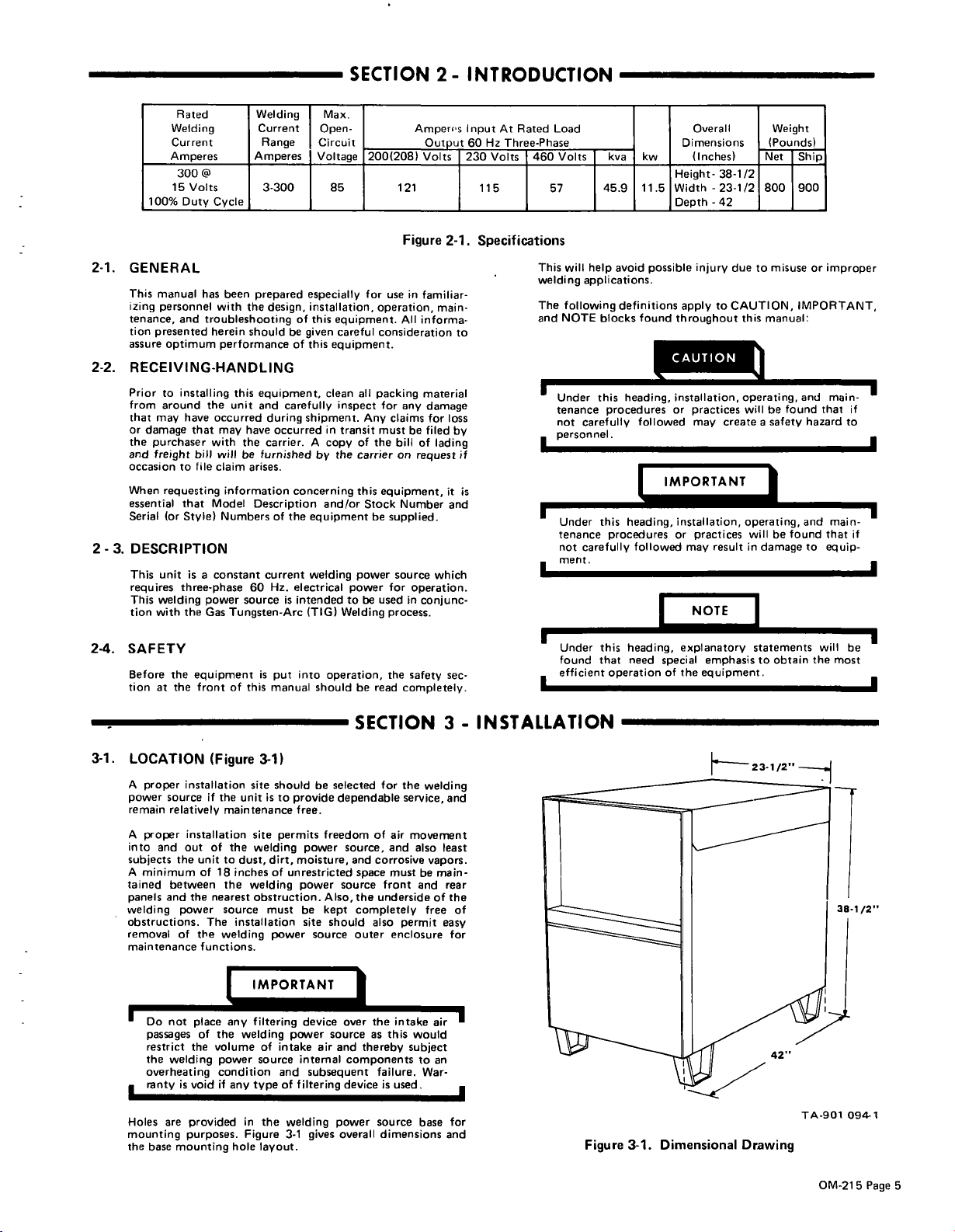
Rated
Welding
Current
Amperes
300
15
Volts
Duty
manual
personnel
and
optimum
to
installing
around
have
that
bill
file
to
requesting
that
(or
Style)
unit
is
three-phase
welding
the
the
equipment
front
Welding
Current
Range
Amperes
@
3-300
Cycle
has
been
prepared
with
the
troubleshooting
herein
design,
should
performance
this
unit
occurred
have
may
the
will
be
claim
arises.
information
Model
Description
Numbers
constant
60
source
Tungsten-Arc
of
this
equipment,
and
during
occurredintransit
carrier.
furnished
of
current
Hz.
is
put
manual
the
a
power
Gas
with
Max.
Open-
Circuit
Voltage
especially
installation,
of
this
be
given
of
this
carefully
shipment.
A
by
concerning
the
equipmentbesupplied.
welding
electrical
intended
is
(TIG)
into
should
85
for
equipment.
careful
equipment.
clean
all
inspect
Any
of
copy
the
carrier
this
Stock
and/or
power
power
be
to
Welding
operation,
be
200(208)
operation,
consideration
packing
the
read
Amper~s
Output
Volts
121
Figure
in
use
familiar
All
informa
material
for
any
claims
be
must
bill
of
on
request
equipment,
Number
source
for
operation.
used
in
conjunc
process.
the
safety
completely.
2-1.
main
damage
for
filed
lading
which
At
Input
Hz
Three-Phase
60
230
Volts
115
Specifications
to
loss
by
if
it
is
and
sec
Rated
460
Load
Volts
kva
kw
Overall
Dimensions
(Inches)
Height-
Width
57
This
will
welding
The
following
NOTE
and
45.9
11.5
avoid
help
applications.
blocks
possible
definitions
found
-23-1/2
-42
Depth
injury
apply
throughout
CAUTION
Under
this
tenance
not
carefully
personnel.
heading,
proceduresorpractices
followed
installation,
may
~TAN~~~
this
I
I
I
Under
tenance
not
carefully
ment.
Under
found
efficient
heading,
proceduresorpractices
this
heading,
that
need
operation
followed
special
installation,
result
may
NOTE
explanatory
emphasis
the
of
equipment.
Weight
(Pounds)
Net
Ship
38-1/2
800
900
duetomisuse
to
CAUTION,
this
opera~~g,
will
create
operating,
will
in
manual:
be
a
safety
be
damage
statements
obtain
to
IMPORTANT,
and
found
found
or
hazard
and
to
the
will
improper
main
if
that
to
main
that
if
equip
be
most
I
I
I
3-1.
LOCATION
A
proper
source
power
remain
relatively
A
proper
into
and
subjects
A
tained
panels
welding
obstructions.
removal
maintenance
Holes
mounting
the
the
minimum
between
and
passages
restrict
the
welding
overheating
ronty
are
base
mounting
(Figure
installation
if
installation
of
out
unit
of18inches
the
nearest
power
The
of
the
functions.
place
the
of
volume
the
is
void
provided
purposes.
3-1)
site
the
maintenance
to
the
source
welding
an
power
condition
if
should
is
unit
to
provide
site
the
permits
welding
dust,
dirt,
of
welding
obstruction.
must
installation
power
unrestricted
jir
welding
any
hole
of
source
type
in
the
Figure
layout.
power
intake
and
of
welding
3-1
be
selected
dependable
free.
freedom
power
moisture,
power
Also,
be
kept
site
should
source
source
air
and
internal
subsequent
filtering
power
overall
gives
SECTION
of
source,
corrosive
and
space
source
the
completely
also
outer
the
r
ove
as
thereby
components
device
for
the
service,
air
movement
and
must
front
underside
permit
enclosure
in
to
this
subject
failure,
is
used
source
dimensions
welding
also
vapors.
be
and
free
ke
air
would
to
War
base
INSTALLATION
-
3
and
least
main
rear
of
the
of
easy
for
an
for
and
Figure
3-1.
Dimensional
Drawing
TA-901
094-1
OM-21
5
Page
5
3-2.
On
most
for
moving
the
lifting
extend
completely
The
use
opposite
ponents
penetrate
ELECTRICAL
It is
recommended
installed
source.
means
the
welding
perform
welding
the
unit,
of
side
to
the
in
This
to
completely
any
power
unit.
be
sure
under
lift
forks
of
damage
bottom
INPUT
the
would
power
internal
sources
However,
that
the
IMPORT
too
base
the
should
of
CONNECTIONS
E~J
that
circuit
input
provide
remove
source
function
a
lifting
ifafork
lift
the
forks
base.
short
to
will
expose
the
the
tips
unit.
Disconnect
Line
a
to
safe
a
electrical
all
wheneveritis
the
on
device
lift
vehicleisused
are
extend
of
the
welding
and
unit
long
Out
internal
the
lift
Switch
convenient
power
necessary
is
provided
enough
of
com
forks
power
from
the
for
to
It
is
recommended
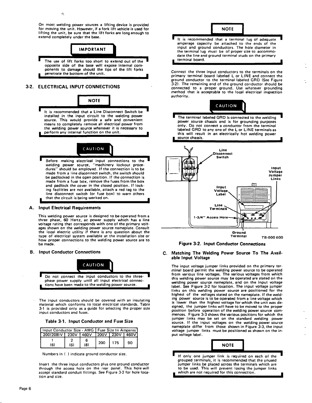
terminal
the
the
terminal
conductor
The
that
terminal
will
capacity
and
ground
lug
line
and
board.
three
remaining
to
a
is
acceptable
source
Do
not
GAD
result
chassis.
board
to
proper
labeled
chassis
connect
to
amperage
input
the
date
terminal
Connect
primary
ground
3-2).
connected
method
authority.
be
to
I
The
power
only.
labeled
this
source
NOTE
that
terminal
conductors.
must
ground
input
the
end
be
attached
be
terminal
conductors
labeled
terminal
of
the
ground.
to
a
of
proper
ground
the
to
The
studs
to
LorLINE
labeled
Use
local
lug
the
hole
size
on
the
conductor
whatever
electrical
CAUTION_j
GRD
is
nected
to
grounding
from
LINE
or
hot
welding
any
in
one
an
con
andisfor
conductor
a
of
the
L
electrically
of
adequate
of
accommo
the
connect
purposes
terminal
the
in
primary
(See
Figure
should
grounding
inspection
welding
as
power
ends
diameter
to
the
terminalsonthe
and
GAD
the
terminals
the
be
A.
B.
I
Before
welding
dures
made
be
made
and
ing
line
that
Input
This
welding
three
voltage
shown
ages
the
local
type
how
be
made.
Input
Do
phase
tions
L
The
input
material
3-1
is
input
Table
Input
200(208)V
should
from
padlocked
fromafuse
padlock
facilities
disconnect
the
Electrical
phase,
rating
on
electric
of
electrical
proper
Conductor
not
power
have
conductors
which
provided
conductors
3-1.
Conductor
1
(6)
making
power
be
line
a
in
the
are
circuit
is
Requirements
power
60
Hertz,
that
corresponds
the
welding
utility
system
connections
Connections
connect
supply
made
been
conforms
only
and
Input
Size
230V
2
(6)
CAUTION
electrical
source.
employed.
disconnect
the
open
box,
cover
not
available,
switch
being
source
ac
if
availableatthe
to
CAUTION
the
input
until
to
should
as
a
fuses.
Conductor
-
AWG
460V
6
(8)
conons
input
machinery
If
the
connection
switch,
the
closed
attachared
fuse
box)
on.
supply
with
one
source
is
any
welding
If
fuses
to
position.
remove
in
the
(or
worked
is
designed
powei-
power
there
the
conducto~he
all
input
the
welding
be
covered
to
local
electrical
for
guide
Fuse
200V
200
selecting
and
Size
lockout
the
switch
the
connection
from
position.
to
warn
be
operated
which
of
the
nameplate.
question
installation
power
electrical
power
with
standards.
the
Fuse
In
Amperes
230V
175
to
is
the
If
tag
has
primary
about
source
connec
source
an
proper
Size
460V
90
the
proce
to
be
should
is
box
lock
the
to
others
from
line
a
volt
Consult
the
site
or
to
are
three-
insulating
Table
size
Line
Input
Voltage
Jumper
Links
a
Ground
C.
Matching
able
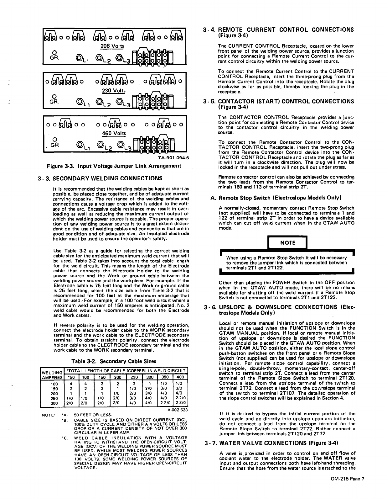
The
minal
from
this
welding
label.
linksonthis
highest
ing
is
signed,
position
mences.
jumper
source.
nameplate
voltage
put
Figure
Input
input
board
various
welding
See
power
lower
voltage
The
voltage
power
Figure
of
the
source
than
the
before
Figure
links
If
the
differ
jumper
3-2.
Input
Welding
Voltage
permit
line
power
source
3-2
welding
voltages
the
jumper
operation
3-3
may
input
links
label.
Conductor
jumper
the
welding
voltages.
source
nameplate,
for
power
statedonthe
is
to
be
highest
links
will
shows
be
set
voltages
from
those
must
Power
links
The
may
location.
source
operated
voltage
have
of
the
the
various
the
on
on
shown
be
positioned
Terminal
Connections
Source
provided
power
various
be
operated
and
The
fromaline
for
be
to
welding
positions
standard
the
source
voltages
on
input
are
nameplate.
which
moved
welding
in
Figure
To
the
on
to
stated
are
the
input
voltage
positioned
voltage
the
to
power
for
welding
power
3-3,
shown
as
TB-000
The
primary
be
operated
from
If
the
unit
was
the
source
which
the
on
600
Avail
ter
which
the
on
voltage
jumper
for
the
weld
which
de
proper
com
the
power
source
input
the
in
Page
Numbers
Insert
through
accept
tion
6
and
in
the
three
the
standard
size.
C
access
indicate
C
input
conduit
conductors
hole
fittings.
ground
the
on
conductor
plus
rear
See
Figure
one
panel.
size.
ground
This
3-2
for
conductor
hole
hole
loca
will
grouped
jumper
be
to
which
one
terminals,
links
used.
not
are
u
j
mper
be
placed
This
required
will
link
it
is
recommended
across
prevent
for
this
uired
req
the
terminals
losing
connection.
the
on
that
ch
ea
the
which
jumper
of
unused
links
he
t
are
~00~
GR.
O~0
&
0
~
Figure
3-
3.
WELDING
AMPERES
100
150
200
250
300
NOTE:
'L1
'L1
0 0 0
'L~
3-3.
Input
SECONDARY
is
recommended
It
possible,
carrying
connections
age
loading
which
tion
dent
good
holder
Use
cable
be
for
cable
power
welding
Electrode
is
recommended
will
maximum
weld
and
If
connect
terminal
terminal.
holder
work
of
the
as
the
of
any
on
condition
must
Table
size
used.
the
weld
that
source
power
25
feet
be
used..
cable
Work
reverse
cable
cabletothe
Table
TOTAL
50
4 4
2 2
1
1/0 1/0
2/0
A.
B.
C.
be
capacity.
arc.
well
welding
the
for
Table
cable
weld
cables.
polarity
the
and
To
50
CABLE
100%
DROP
CIRCULAR
WELD
RATING
AGE
BE
HAVE
100
SPECIAL
VOLTAGE.
~OO~
V
208
'L2
0~O.0~I~O
230
~L2
0
0
460
~L2
Voltage
WELDING
the
that
close
placed
cause
Excessive
welding
use
and
used
be
3-2
the
3-2
circuit.
connects
and
source
long,
for
For
would
electrode
the
obtain
the
to
3-2.
LENGTH
100 150
1
2/0
FEET
DUTY
ORACURRENT
IOCVI
USED.
VOLTS,
together,
The
resistance
a
voltage
as
reducing
power
power
of
welding
of
adequate
ensure
to
as
a
guide
anticipated
takes
This
the
Work
the
and
is
75
feet
select
the
feet
100
example,
of
current
recommended
be
istobe
holder
work
cabletothe
straight
ELECTRODE
WORK
Secondary
OF
2 2
2
1
1/0
2/0
OR
LESS.
SIZE
IS
CYCLE
MILS
CABLE
WITHSTAND
TO
THE
OF
WHILE
OPEN-CIRCUIT
AN
SOME
DESIGN
cable
source
into
means
the
secondary
CABLE
BASED
PER
INSULATION
MAY
~O0~
__
Volts
'
LJt0101O]~LJ
L3
0
0
0
0
00
Volts
'L3fl~fl
TA-901
094-6
Link
cables
of
be
of
the
weldIng
is
may
capable.
is
to
a
great
connections
An
the
weld
the
length
Holder
ground
For
Work
the
from
maximum
foot
weld
is
for
both
the
ELECTRODE
connect
secondary
terminal.
Sizes
250
300
2
2/0
1/0
3/0
2/0
4/0 4/0
3/0
4/0
DIRECT
A
OF
WITH
OPEN-CIRCUIT
THE
POWER
VOLTAGE
POWER
HIGHER
Arrangement
short
as
be
kept
adequate
cables
to
result
proper
extent
safety.
correct
current
cable
the
of
the
to
between
example:
or
ground
Table
amperage
circuit
the
the
terminal
WELD
350
1/0
3/0 3/0
4/0
22/0
CURRENT
VOLTS
NOT
A
SOURCE
LESS
OF
SOURCES
OPENCIRCUIT
the
output
that
electrode
that
Electrode
3-2
Electrode
operation,
secondary
secondary
electrode
CIRCUIT
A-002
OR
OVER
VOLTAGE
SOURCES
added
current
The
insulated
total
cable
anticipated,
welding
WORK
IN
1
4
POWER
as
current
and
volt
in
over
of
opera
depen
are
welding
will
length
welding
the
If
the
cable
that
that
where
No.
the
and
400
1)0
4/0
2-2/0
2-3/0
623
IDC),
LESS
300
VOLT
MUST
THAN
OF
in
is
a
2
Jumper
CONNECTIONS
welding
and
which
drop
resistance
the
maximum
is
source
cables
and
size.
the
operators
for
selecting
maximum
account
the
Electrode
or
workpiece.
and
long
size
cable
the
at
in
100
a
150
amperes
used
for
cabletothe
polarity,
Cable
(COPPERI
200
1
1/0
210
3/0
4/0
ON
AND
EITHER
DENSITY
AMP.
WELDING
MOST
WELDING
WELDING
HAVE
3-4.
3-5.
A.
3-6.
3-7.
REMOTE
(Figure
The
front
point
rent
To
connect
CONTROL
Remote
clockwise
CURRENT CONTROL
3-4)
CURRENT
of
panel
for
connecting
control
circuitry
the
Receptacle,
Current
as
receptacle.
CONTACTOR
(Figure
The
tion
to
source.
To
TACTOR
from
TACTOR
it
locked
Remote
the
minals
Remote
A
122
which
mode.
Other
when
available
Switch
3-4)
CONTACTOR
for
point
the
contactor
Connect
CONTROL
Remote
the
CONTROL
will
turn
in
the
contactor
leads
two
160
and
Stop
normally-closed,
(not
supplied)
of
terminal
cut
can
When
using
to
remove
terminals
than
the
in
for
is
not
in
placing
UPSLOPE
the
the
slope
it is
not
valve
or
not
MANUAL
of
GTAW
(not
to
switch
desired
cycle
link
and
that
Models
remote
be
upslope
For
terminal
lead
a
2T72.
control
and
Connect
Slope
between
VALVE
is
provided
water
output
troslope
Local
should
GTAW
tion
Switch should
in
push-button
Switch
initiation.
single-pole,
switch
terminalofthe
Connect
terminal
of
the
If
weld
do
Remote
jumper
WATER
A
coolant
input
Ensure
CONTROL
the
welding
a
within
Remote
Control
far
as
possible,
(START)
CONTROL
connecting
control
Remote
the
Contactor
clockwise
a
Receptacle,
Receptacle
receptacle
control
the
from
terminal
113
of
Switch
momentary
will
havetobe
2Tinorder
strip
off
weld
Remote
a
the
jumper
and
the
GTAW
DOWNSLOPE
2T122.
AUTO
off
2T1
shutting
connected
&
Only)
manual
used
when
position.
or
downslope
be
placed
AUTO
remote
strip
Remote
from
Connect
terminal
to
switches
to
bypass
go
a
Switch
the
to
connections
hose
position,
on
can
the
directly
lead
terminals
CONNECTIONS
in
electrode
from
switches
supplied)
double-throw,
the
Receptacle,
power
the
Current
thereby
source,
Current
welding
Control
the
three-prong
the
receptacle.
locking
Remote
insert
into
CONTROL
Receptacle
Remote
a
and
can
Remote
(Electroslope
current
Contactor
circuitry
Contactor
insert
Control
and
direction.
will
not
pull
alsobeachieved
Contactor
2T.
strip
contact
connected
to
when
in
Control
device
rotate
The
Models
have
NOTE
Switch
Stop
link
POWER
the
terminals
to
which
mode,
weld
it
is
connected
Switchinthe
there
current
2T1
CONNECTIONS
initiation
the
In
the
be
slope
2T.
Slope
upslope
lead
a
2T107.
will
the
from
terminal
to
ordertocontrol
the
of
upslope
FUNCTION
If
local
the
front
used
control
momentary-contact,
Connect
be
into
2T1
both
water
or
Is
desired
GTAW
either
panel
for
Switch
terminal
from
The
explained
initial
upslope
the
upslope
2T72.
20
holder.
remote
AUTO
the
upslope
capability,
a
the
current
and
have
source
CONNECTIONS
located
on
provides
Control
source.
power
the
to
plug
Rotate
the
CONNECTIONS
provides
Control
the
welding
to
the
two-prong
into
the
plug
will
plug
under
out
by
Control
Only)
Remote
in
detailed
terminals
to
device
a
GTAW
the
be
will
OFF
will
be
Remote
if
a
2T122.
and
or
Switch
manual
the
position.
local
slope
Remote
a
or
or
from
lead
terminal
to
of
the
downslope
Section
in
portion
arc
upon
terminal
Rather
2T72.
(Figure
and
on
WATER
The
left-hand
attached
is
Stop
necessary
FUNCTION
operation
3-4)
the
lower
a
junction
the
to
cur
CURRENT
from
the
the
plug
in
the
plug
a
junc
device
power
the
CON
plug
CON
the
far
as
now
stress.
connecting
ter
to
Switch
1
and
available
AUTO
between
position
no
means
Stop
(Elec
-
downslope
in
is
initia
When
control
Slope
downslope
connect
center-off
the
center
2T1
switch
terminal
4.
of
initiation,
on
Connect
off
flow
valve
threading.
to
OM-215
as
be
the
20.
to
of
the
the
of
the
Page
a
8
7
 Loading...