

Miller AC 150 Stick, AC 200 Stick Owner's Manual
OM-194 415 May 1999
Effective with serial number:
150 - 151968
200 - 151969
Processes
Stick (SMAW) Welding
Description
AC 150 Stick and
AC 200 Stick
Visit our website at
www.MillerWelds.com
From Miller to You
Thank you and congratulations on choosing Miller. Now
you can get the job done and get it done right. We know
you don’t have time to do it any other way.
That’s why when Niels Miller first started building arc
welders in 1929, he made sure his products offered
long-lasting value and superior quality. Like you, his
customers couldn’t afford anything less. Miller products
had to be more than the best they could be. They had to
be the best you could buy.
Today, the people that build and sell Miller products continue the
tradition. They’re just as committed to providing equipment and service
that meets the high standards of quality and value established in 1929.
This Owner’s Manual is designed to help you get the most out of your
Miller products. Please take time to read the Safety precautions. They will
help you protect yourself against potential hazards on the worksite. We’ve
made installation and operation quick and easy. With Miller you can
count on years of reliable service with proper maintenance. And if for
some reason the unit needs repair, there’s a Troubleshooting section that
will help you figure out what the problem is. The parts list will then help
you to decide which exact part you may need to fix the problem.
Warranty and service information for your particular model are also
provided.
Miller Electric manufactures a full line
of welders and welding related equipment.
For information on other quality Miller
products, contact your local Miller distributor
to receive the latest full line catalog or
individual catalog sheets.
Working as hard as you do every power source from
Miller is backed by the most
hassleĆfree warranty in the
business.

TABLE OF CONTENTS
SECTION 1 – SAFETY PRECAUTIONS FOR ARC WELDING 1. . . . . . . . . . . .
1-1. Symbol Usage 1. . . . . . . . . . . . . . . . . . . . . . . . . . . . . . . . . . . . . . . . . . . . . . . . .
1-2. Arc Welding Hazards 1. . . . . . . . . . . . . . . . . . . . . . . . . . . . . . . . . . . . . . . . . . .
1-3. Additional Installation, Operation, And Maintenance Hazards 2. . . . . . . .
1-4. Principal Safety Standards 2. . . . . . . . . . . . . . . . . . . . . . . . . . . . . . . . . . . . . .
1-5. EMF Information 2. . . . . . . . . . . . . . . . . . . . . . . . . . . . . . . . . . . . . . . . . . . . . . .
SECTION 2 – INSTALLATION 3. . . . . . . . . . . . . . . . . . . . . . . . . . . . . . . . . . . . . . . . .
2-1. Specifications 3. . . . . . . . . . . . . . . . . . . . . . . . . . . . . . . . . . . . . . . . . . . . . . . . .
2-2. Selecting A Location 3. . . . . . . . . . . . . . . . . . . . . . . . . . . . . . . . . . . . . . . . . . .
2-3. Typical Connections 4. . . . . . . . . . . . . . . . . . . . . . . . . . . . . . . . . . . . . . . . . . . .
2-4. Weld Output Terminals And Selecting Cable Sizes 4. . . . . . . . . . . . . . . . . .
2-5. Electrical Service Guide 4. . . . . . . . . . . . . . . . . . . . . . . . . . . . . . . . . . . . . . . .
2-6. Connecting Input Power 5. . . . . . . . . . . . . . . . . . . . . . . . . . . . . . . . . . . . . . . .
SECTION 3 – OPERATION 6. . . . . . . . . . . . . . . . . . . . . . . . . . . . . . . . . . . . . . . . . . .
3-1. Controls For AC 150 Stick 6. . . . . . . . . . . . . . . . . . . . . . . . . . . . . . . . . . . . . . .
3-2. Controls For AC 200 Stick 6. . . . . . . . . . . . . . . . . . . . . . . . . . . . . . . . . . . . . . .
SECTION 4 – MAINTENANCE AND TROUBLESHOOTING 7. . . . . . . . . . . . . . .
4-1. Routine Maintenance 7. . . . . . . . . . . . . . . . . . . . . . . . . . . . . . . . . . . . . . . . . . .
4-2. Troubleshooting 8. . . . . . . . . . . . . . . . . . . . . . . . . . . . . . . . . . . . . . . . . . . . . . .
SECTION 5 – ELECTRICAL DIAGRAMS 9. . . . . . . . . . . . . . . . . . . . . . . . . . . . . . .
SECTION 6 – PARTS LIST 12. . . . . . . . . . . . . . . . . . . . . . . . . . . . . . . . . . . . . . . . . . .

Declaration of Conformity
“CE” Dichiarazione di Conformità
Manufacturer’s Name:
Nome del Costruttore:
Manufacturer’s Address:
Indirizzo Costruttore:
MILLER Europe S.p.A.
Via Privata Iseo, 6/E
20098 San Giuliano
Milanese, Italy
Declares that this product:
Dichiara che il Prodotto:
AC 150 Stick
AC 200 Stick
Conforms to the following Directives and Standards:
È Conforme alle seguenti Direttive e Norme.
Electromagnetic Compatibility Directives: 89/336/EEC
Compatibilità Elettromagnetica: (EMC) 89/336/CEE
Low Voltage: 73/23/EEC
Direttiva bassa tensione: 73/23/CEE
Machinery Directives: 89/392/EEC
Direttiva Macchine: 89/392/CEE
And their amendments 91/368/EEC, 93/31/EEC, 93/44/EEC, 93/68/EEC
Aggiornate dalle direttive 91/368/CEE, 93/31/CEE 93/44/CEE, 93/68/CEE
Direttive
Norme
Electromagnetic compatibility (EMC) Product standard for arc welding equipment:
EN50199: August 1995
Norma sulla compatibilità elettromagnetica (EMC) dei prodotti per apparecchi di saldatura ad arco:
EN50199, agosto 1995
Safety Requirements for Arc Welding Equipment part 1: EN 60974-1, 1989
Prescrizioni di sicurezza per apparecchi di saldatura ad arco, Sezione 1: EN 60974-1, 1989
European Contact: Mr. Luigi Vacchini, Managing Director
In Europa Contattare: MILLER Europe S.P.A.
Via Privata Iseo, 6/E
20098 San Giuliano
Milanese, Italy
Telefono: 39(0)2-982901
Fax: 39(0)2-98290-203
dec_con_ita 5/97
SECTION 1 – SAFETY PRECAUTIONS FOR ARC WELDING
safety_stickom1 6/95
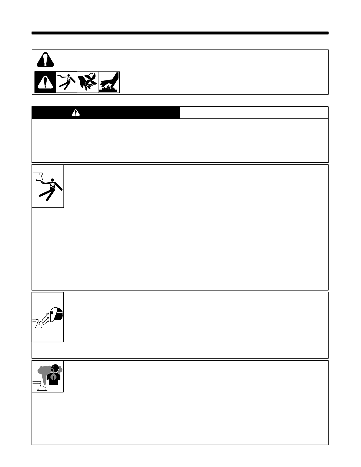
1-1. Symbol Usage
Means Warning! Watch Out! There are possible hazards with this
procedure! The possible hazards are shown in the adjoining symbols.
This group of symbols means Warning! Watch Out! possible ELECTRIC SHOCK, MOVING P ARTS,
and HOT P ARTS hazards. Consult symbols and related instructions below for necessary actions to
avoid the hazards.
Y Marks a special safety message.
. Means NOTE; not safety related.
1-2. Arc Welding Hazards
WARNING
The symbols shown below are used throughout this manual to call attention to and identify possible
hazards. When you see the symbol, watch out, and follow the related instructions to avoid the hazard. The
safety information given below is only a summary of the more complete safety information found in the
Safety Standards listed in Section 1-4. Read and follow all Safety Standards.
Only qualified persons should install, operate, maintain, and repair this unit.
During operation, keep everybody, especially children, away.
ELECTRIC SHOCK can kill.
Touching live electrical parts can cause fatal shocks
or severe burns. The electrode and work circuit is
electrically live whenever the output is on. The input
power circuit and machine internal circuits are also
live when power is on. Incorrectly installed or
improperly grounded equipment is a hazard.
1. Do not touch live electrical parts.
2. Wear dry , hole-free insulating gloves and body protection.
3. Insulate yourself from work and ground using dry insulating mats
or covers big enough to prevent any physical contact with the
work or ground.
4. Disconnect input power before installing or servicing this
equipment. Lockout/tagout input power according to OSHA 29
CFR 1910.147 (see Safety Standards).
5. Properly install and ground this equipment according to its
Owner’s Manual and national, state, and local codes.
6. Always verify the supply ground – check and be sure that input
power cord ground wire is properly connected to ground terminal
in disconnect box or that cord plug is connected to a properly
grounded receptacle outlet.
7. When making input connections, attach proper grounding
conductor first – double-check connections.
8. Frequently inspect input power cord for damage or bare wiring –
replace cord immediately if damaged – bare wiring can kill.
9. Turn off all equipment when not in use.
10. Do not use worn, damaged, undersized, or poorly spliced cables.
11. Do not drape cables over your body.
12. If earth grounding of the workpiece is required, ground it directly
with a separate cable – do not use work clamp or work cable.
13. Do not touch electrode if you are in contact with the work, ground,
or another electrode from a different machine.
14. Use only well-maintained equipment. Repair or replace damaged
parts at once. Maintain unit according to manual.
15. Wear a safety harness if working above floor level.
16. Keep all panels and covers securely in place.
17. Clamp work cable with good metal-to-metal contact to workpiece
or worktable as near the weld as practical.
ARC RAYS can burn eyes and skin;
NOISE can damage hearing; FLYING
SLAG OR SPARKS can injure eyes.
Arc rays from the welding process produce intense
visible and invisible (ultraviolet and infrared) rays
that can burn eyes and skin. Noise from some
processes can damage hearing. Chipping, grinding,
NOISE
1. Use approved ear plugs or ear muffs if noise level is high.
and welds cooling throw off pieces of metal or slag.
FUMES AND GASES can be
hazardous to your health.
Welding produces fumes and gases. Breathing
these fumes and gases can be hazardous to your
health.
1. Keep your head out of the fumes. Do not breathe the fumes.
2. If inside, ventilate the area and/or use exhaust at the arc to
remove welding fumes and gases.
3. If ventilation is poor, use an approved air-supplied respirator.
4. Read the Material Safety Data Sheets (MSDSs) and the
manufacturer’s instruction for metals, consumables, coatings,
cleaners, and degreasers.
ARC RAYS
2. Wear a welding helmet fitted with a proper shade of filter to protect
your face and eyes when welding or watching (see ANSI Z49.1
and Z87.1 listed in Safety Standards).
3. Wear approved safety glasses with side shields.
4. Use protective screens or barriers to protect others from flash
and glare; warn others not to watch the arc.
5. Wear protective clothing made from durable, flame-resistant
material (wool and leather) and foot protection.
5. Work in a confined space only if it is well ventilated, or while
wearing an air-supplied respirator. Always have a trained
watchperson nearby. Welding fumes and gases can displace air
and lower the oxygen level causing injury or death. Be sure the
breathing air is safe.
6. Do not weld in locations near degreasing, cleaning, or spraying
operations. The heat and rays of the arc can react with vapors to
form highly toxic and irritating gases.
7. Do not weld on coated metals, such as galvanized, lead, or
cadmium plated steel, unless the coating is removed from the
weld area, the area is well ventilated, and if necessary, while
wearing a n air-supplied respirator. The coatings and any metals
containing these elements can give off toxic fumes if welded.
OM-194 415
CYLINDERS can explode if damaged.
Shielding gas cylinders contain gas under high
pressure. If damaged, a cylinder can explode. Since
gas cylinders are normally part of the welding
process, be sure to treat them carefully.
1. Protect compressed gas cylinders from excessive heat,
mechanical shocks, slag, open flames, sparks, and arcs.
2. Keep cylinders away from any welding or other electrical circuits.
3. Never drape an electrode holder over a gas cylinder .
4. Never allow a welding electrode to touch any cylinder.
5. Never weld on a pressurized cylinder – explosion will result.
WELDING can cause fire or
explosion.
Welding on closed containers, such as tanks,
drums, or pipes, can cause them to blow up. Sparks
can fly off from the welding arc. The flying sparks,
hot workpiece, and hot equipment can cause fires
and burns. Accidental contact of electrode to metal
objects can cause sparks, explosion, overheating,
or fire. Check and be sure the area is safe before
doing any welding.
1. Protect yourself and others from flying sparks and hot metal.
2. Do not weld where flying sparks can strike flammable material.
3. Remove all flammables within 35 ft (10.7 m) of the welding arc. If
this is not possible, tightly cover them with approved covers.
4. Be alert that welding sparks and hot materials from welding can
easily go through small cracks and openings to adjacent areas.
5. Watch for fire, and keep a fire extinguisher nearby .
6. Be aware that welding on a ceiling, floor, bulkhead, or partition
can cause fire on the hidden side.
7. Do not weld on closed containers such as tanks, drums, or pipes,
unless they are properly prepared according to AWS F4.1 (see
Safety Standards).
8. Connect work cable to the work as close to the welding area as
practical to prevent welding current from traveling long, possibly
unknown paths and causing electric shock and fire hazards.
9. Do not use welder to thaw frozen pipes.
10. Remove stick electrode from holder when not in use.
11. Wear oil-free protective garments such as leather gloves, heavy
shirt, cuffless trousers, high shoes, and a cap.
12. Remove any combustibles, such as a butane lighter or matches,
from your person before doing any welding.
1-3. Additional Installation, Operation, And Maintenance Hazards
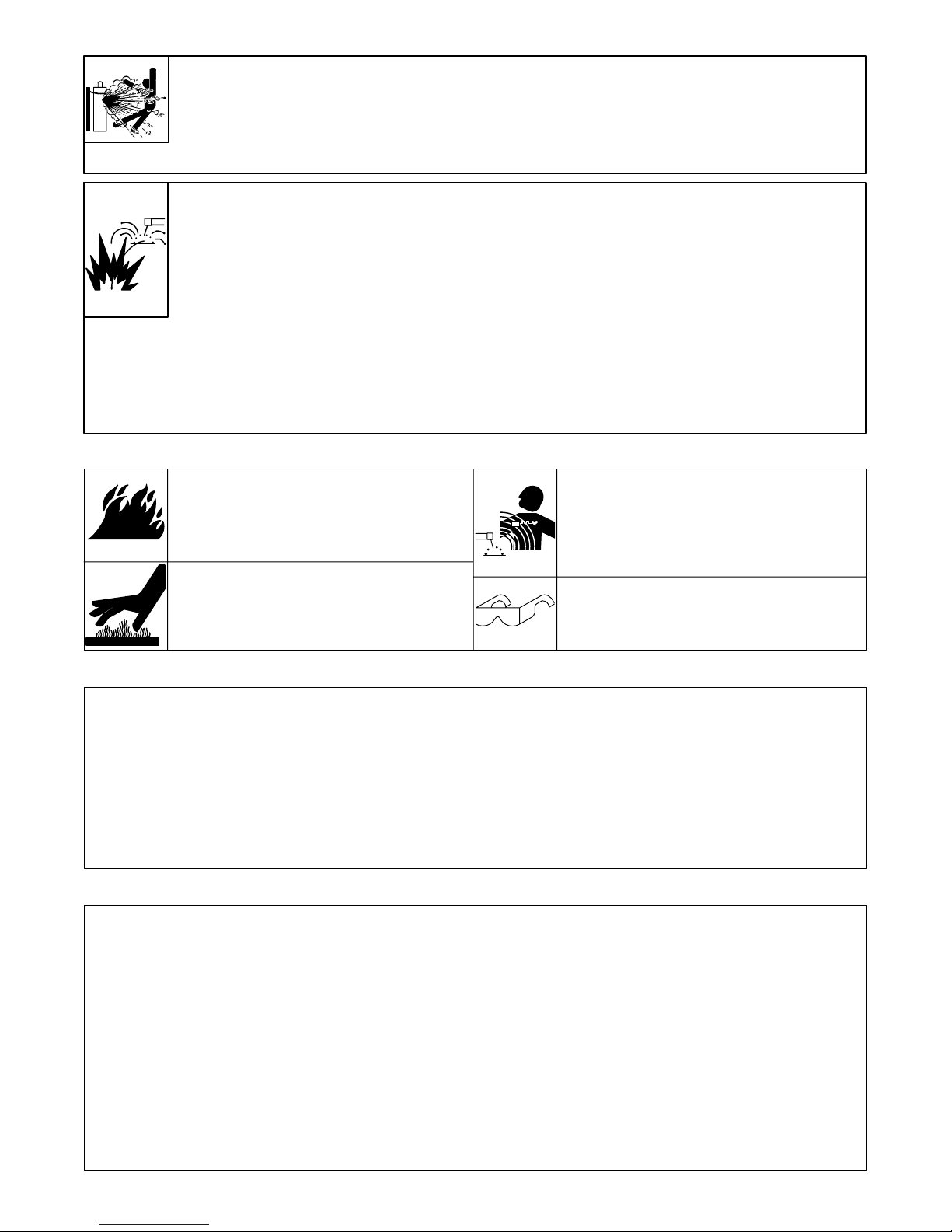
FIRE OR EXPLOSION can result from
placing unit on, over, or near
combustible surfaces.
1. Do not install unit on, over, or near combustible
surfaces or flammables.
HOT PARTS can cause severe burns.
1. Do not touch hot parts bare handed. Allow cooling
period before touching welded parts.
MAGNETIC FIELDS FROM HIGH
CURRENTS can affect pacemaker
operation.
1. Wearers should consult their doctor before going
near arc welding, gouging, or spot welding
operations.
FLYING PIECES OF METAL or DIRT can
injure eyes.
1. Wear safety glasses with side shields or face
shield.
1-4. Principal Safety Standards
Safety in Welding and Cutting, ANSI Standard Z49.1, from American
Welding Society, 550 N.W. LeJeune Rd, Miami FL 33126
Safety and Health Standards, OSHA 29 CFR 1910, from
Superintendent of Documents, U.S. Government Printing Office,
Washington, D.C. 20402.
Recommended Safe Practices for the Preparation for Welding and
Cutting of Containers That Have Held Hazardous Substances,
American Welding Society Standard AWS F4.1, from American
Welding Society, 550 N.W. LeJeune Rd, Miami, FL 33126
1-5. EMF Information
Considerations About Welding And The Effects Of Low Frequency
Electric And Ma g netic Fields
The following is a quotation from the General Conclusions Section of
the U.S. Congress, Office of Technology Assessment, Biological
Effects of Power Frequency Electric & Magnetic Fields – Background
Paper, OTA-BP-E-53 (Washington, DC: U.S. Government Printing
Office, May 1989): “. . . there is now a very large volume of scientific
findings based on experiments at the cellular level and from studies
with animals and people which clearly establish that low frequency
magnetic fields can interact with, and produce changes in, biological
systems. While most of this work is of very high quality , the results are
complex. Current scientific understanding does not yet allow us to
interpret the evidence in a single coherent framework. Even more
frustrating, i t does not yet allow us to draw definite conclusions about
questions of possible risk or to offer clear science-based advice on
strategies to minimize or avoid potential risks.”
National Electrical Code, NFPA Standard 70, from National Fire
Protection Association, Batterymarch Park, Quincy, MA 02269.
Code for Sa fety in Welding and Cutting, CSA Standard W117.2, from
Canadian Standards Association, Standards Sales, 178 Rexdale
Boulevard, Rexdale, Ontario, Canada M9W 1R3.
Safe Practices For Occupation And Educational Eye And Face
Protection, ANSI Standard Z87.1, from American National Standards
Institute, 1430 Broadway, New York, NY 10018.
Cutting And Welding Processes, NFP A Standard 51B, from National
Fire Protection Association, Batterymarch Park, Quincy, MA 02269.
To reduce magnetic fields in the workplace, use the following
procedures:
1. Keep cables close together by twisting or taping them.
2. Arrange cables to one side and away from the operator.
3. Do not coil or drape cables around the body.
4. Keep welding power source and cables as far away as
practical.
5. Connect work clamp to workpiece as close to the weld as
possible.
About Pacemakers:
The above procedures are also recommended for pacemaker
wearers. Consult your doctor for complete information.
OM-194 415 Page 2
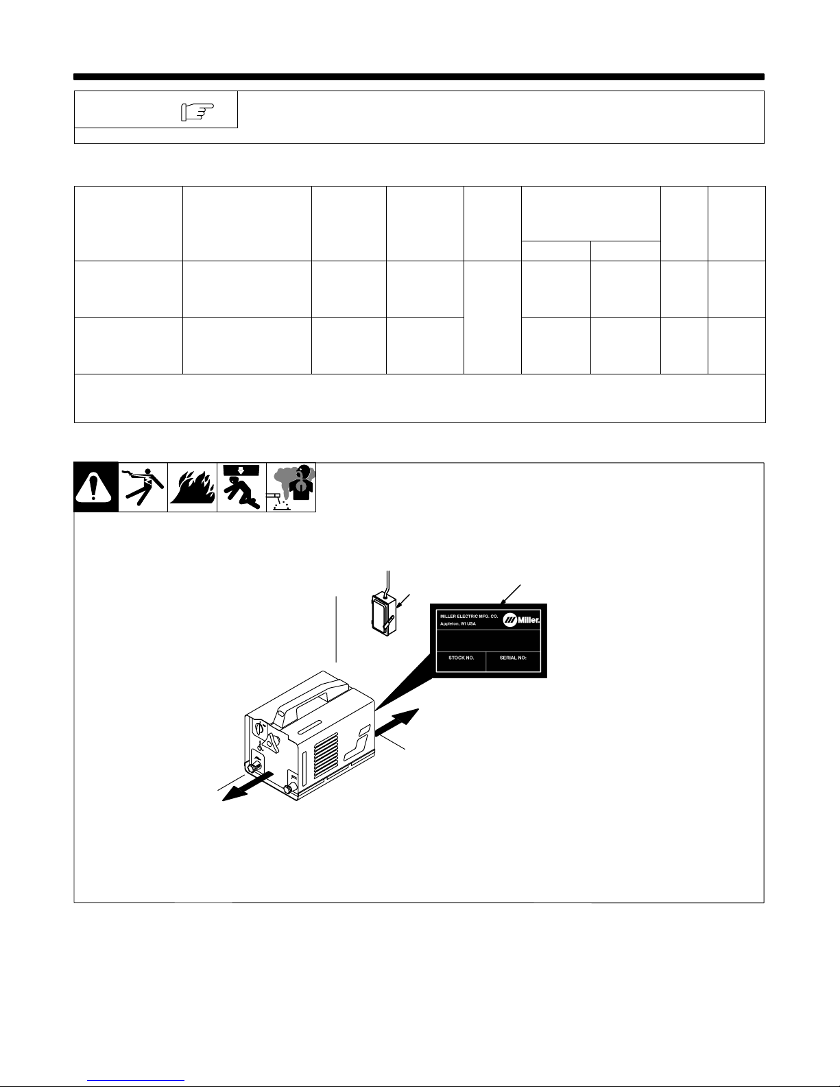
SECTION 2 – INSTALLATION
NOTE
The AC 150 Stick model is shown in illustrations throughout this manual. Unless
otherwise specified, procedures apply to both models.
2-1. Specifications
Model Rated Welding Output
AC 150 Stick
AC 200 Stick
See Rating Label
On Unit
See Rating Label
On Unit
AC 150 Stick: Height: 315 mm; Width: 255 mm; Length: 410 mm
AC 200 Stick: Height: 570 mm; Width: 340 mm; Length: 670 mm
2-2. Selecting A Location
Amp
Range AC
50 - 130 A
35 - 190 A
Maximum
Open-Circuit
Voltage AC
Voltage AC
48
48
Dimensions:
2
IP
Rating
IP21
Amperes Input at
Rated Load Output,
50/60 Hz, Single-Phase
230 V 400 V
28 16 4 16 kg
37 22 4.4 23 kg
1 Rating Label
Use rating label to determine input
power needs.
2 Line Disconnect Device
Locate unit near correct input pow-
er supply.
1
Y Special installation may be
required where gasoline or
volatile liquids are present –
see NEC Article 511 or CEC
Section 2 0 .
KVA Weight
18 in
(460 mm)
18 in
(460 mm)
OM-194 415 Page 3
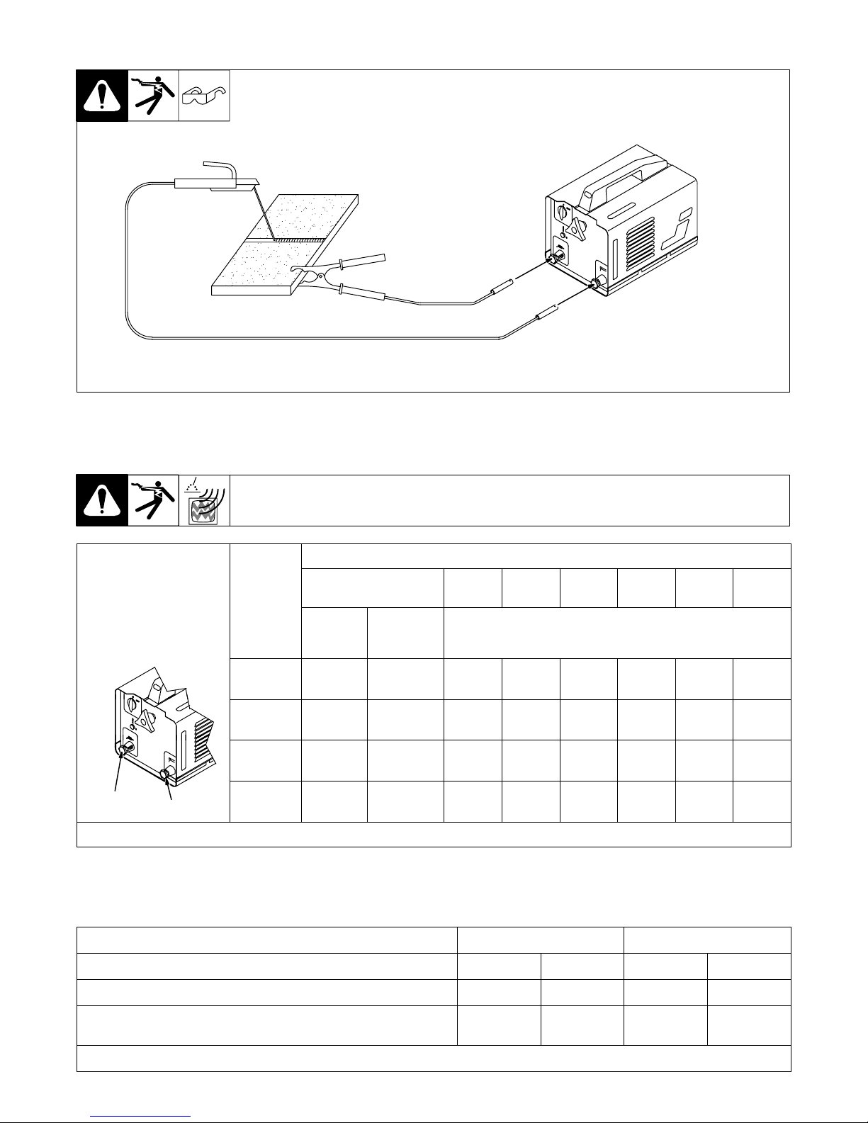
2-3. Typical Connections
Typical Stick (SMAW) Connections
2-4. Weld Output Terminals And Selecting Cable Sizes
Total Cable (Copper) Length In Weld Circuit Not Exceeding
100 ft (30 m) Or Less
Turn Off power before
connecting to weld output
receptacles.
Ground
Weld cable size (mm2) is based on either a 4 volts or less drop or a current density of at least 300 circular mils per ampere. Ref. S-0007-D
Electrode
Welding
Amperes
100 20 20 20 25 35 50 50 50
150 25 25 35 50 50 70 90 90
200 25 35 50 50 70 90 90 90
250 35 35 50 70 90 90 120 120
10 – 60%
Duty
Cycle
60 – 100%
Duty Cycle
150 ft
(45 m)
200 ft
(60 m)
250 ft
(70 m)
10 – 100% Duty Cycle
300 ft
(90 m)
350 ft
(105 m)
400 ft
(120 m)
2-5. Electrical Service Guide
Model AC 150 Stick AC 200 Stick
Input Voltage 230 400 230 400
Input Amperes At Rated Output 28 16 37 22
Max Recommended Standard Fuse Or Circuit Breaker Rating In
Amperes
Reference: 1997 National Electrical Code (NEC) S-0092-J
OM-194 415 Page 4
30 20 40 25
 Loading...