

Page 1
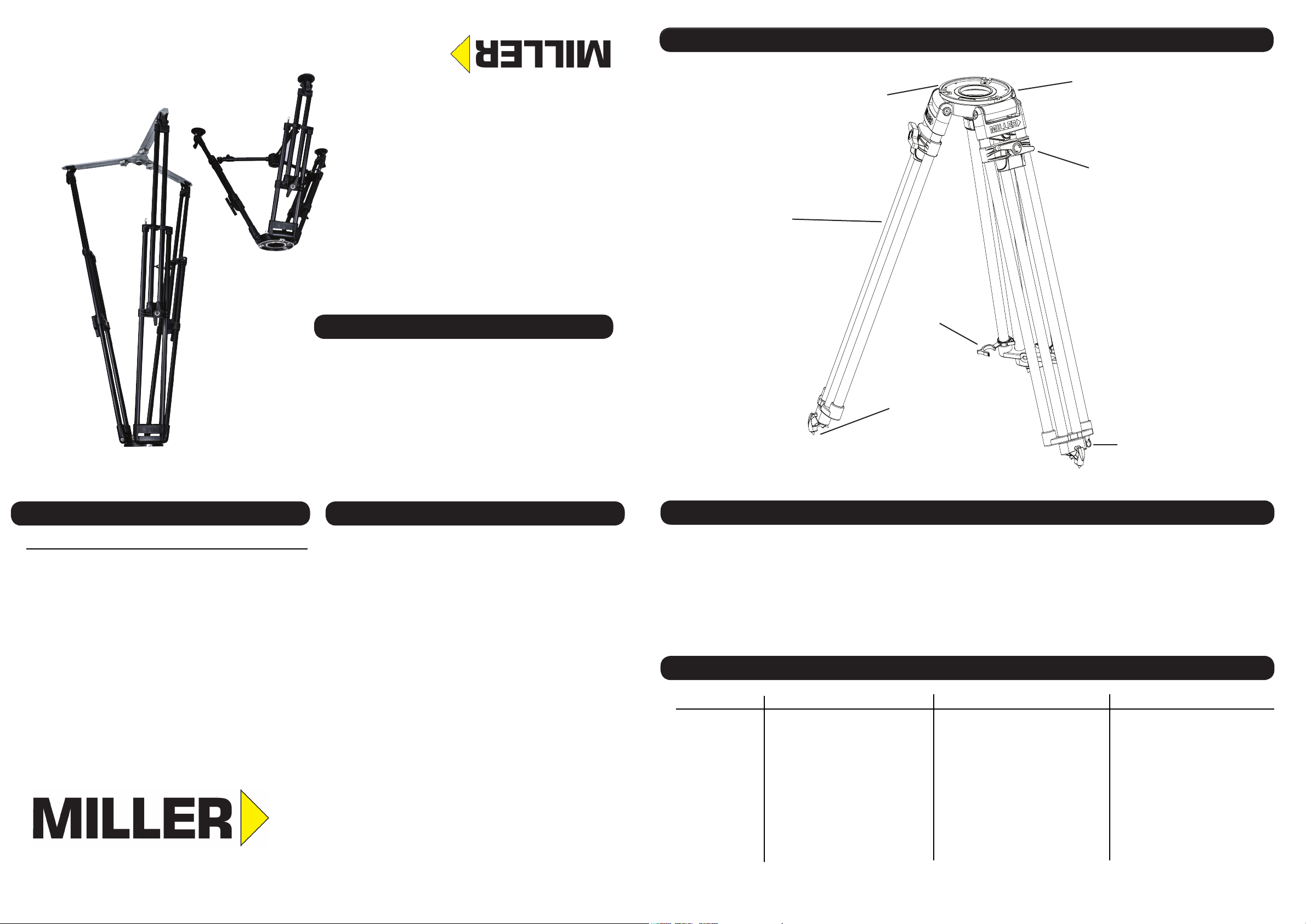
FEATURES AND CONTROLS
Mitchell base
Bubble Level (only on MB model)
#2116/G HDC 150 TALL
#2115/G HDC 150
#2114/G HDC 150 SHORT
150mm Bowl Models
#2122/G HDC 100 TALL
#2121/G HDC 100
#2120/G HDC 100 SHORT
100mm Bowl Models
#2111/G HDC MB TALL
#2110/G HDC MB
#2109/G HDC MB SHORT
Mitchell Base Models
Single stage alloy tubing
Available in:
- Short
- Standard
- Tall
Also available in
- 100mm bowl
- 150mm bowl
Leg lock lever
ACCESSORIES & COMPONENTS SERVICE, SALES & SUPPORT
Cat # Description
#2130 HDC Ground Spreader
#2132 HDC Ground Spreader Short
#478 HD Rubber Feet (set of 3)
#993 Mid Level Spreader
#3222 HD Dolly
Miller Authorised Service Agents must carry out all service and repair work.
Failure to observe this requirement may void warranty. It is advisable to
notify Miller or a MIller Authorised Service Agent if a change of perform-
ance is observed as a result of dropping or rough usage. For information
regarding sales and service of Miller products, or for your nearest Miller
representative please contact us via our website or at the following:
MILLER CAMERA SUPPORT EQUIPMENT
30 Hotham Parade
Sydney, NSW, 2064, Australia
Tel: +61 2 9439 6377
Fax: +61 2 9438 2819
Email: sales@miller.com.au
MILLER FLUID HEADS (Europe) LTD.
12A Shepperaton Business Park
Govett Avenue, Shepparton
Middlesex TW17 8BA, United Kingdom
Tel: +44 (0)1243 555 255
Fax:+44 (0)1243 555 001
Email: sales@millertripods-europe.com
MILLER CAMERA SUPPORT LLC (USA)
216 Little Falls Road (unit 15 & 16)
Cedar Grove, New Jersey, 07009, USA
Tel: (973) 857 8300
Fax: (973) 857 8188
Email: sales@millertripods.us
D9631-1 02/19
O P E R A T O R ’ S M A N U A L
HDC
INTRODUCTION
Thank you for purchasing the HDC Tripod.
The HDC tripod range is specifically built for cinematographers and outside broadcasters who demand the highest levels of stability, low torsional distortion,
even at maximum drag. The HDC range is differentiated by the mounting base, the height and the spreader type, the quick action rotary screw type leg locks
allow for maximum lock off performance without need for maintenance.
No matter where your work takes you, the HDC tripod series performs in extreme environments and terrains every time.
TECHNICAL DATA
Cat# 2109/G 2110/G 2111/G 2114/G 2115/G 2116/G 2120/G 2121/G
Base MB MB MB 150mm
Height Short Standard Tall Short Standard Tall Short Standard
Material Alloy Alloy Alloy Alloy Alloy Alloy Alloy Alloy
Maximum Load kg (lb) 95 (210) 95 (210) 95 (210) 95 (210) 95 (210) 95 (210) 95 (210) 95 (210)
Weight kg (lb) 4.8 (10.6) 5.9 (13.2) 6.4 (14.1) 5.6 (12.4) 6.2 (13.7) 4.3 (9.5) 5.4 (11.9) 6.0 (13.2)
Max Height mm (in) 900 (35.4) 1549 (61.0) 1764 (69.5) 1539 (60.6) 1754 (69.1) 900 (35.4) 1539 (60.6) 1690 (66.5)
Min Height mm (in) 415 (16.4) 737 (29.0) 886 (34.9) 727 (28.2) 876 (34.5) 370 (14.6) 710 (28.0) 845 (33.3)
Transport Length mm (in)
610 (24.0) 916 (36.1) 1010 (39.8)
Transport clip
Steel spikes
Adapts to:
#478 HD Feet (non “G” model)
#475 Feet (non “G” model)
#2130 Spreader (“G” model)
#2132 Spreader (“G” model)
150mm
4.5 (9.9)
890 (35.0)
405 (16.0)
600 (23.6)
906 (35.7) 1000 (39.4) 600 (23.6)
Split ring for transport strap (opt.)
2122/G
150mm
Specs based on ‘G’ variant - ‘non-G’ variant will have lower Min Height
100mm
100mm
906 (35.7)
100mm
Tall
Alloy
95 (210)
1000 (39.4)
Page 2
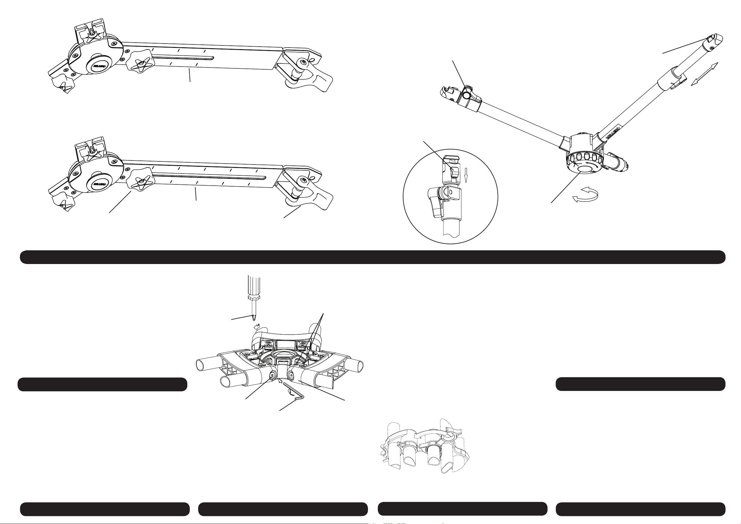
866-1146mm
Spreader arm length
Telescopic clamp
Quick release latch
Spreader adjusting knob
the camera and fluid head is attached.
5. Do not remove the Mid Level Spreader or Ground Spreader whilst
Head.
4. Do not move the Tripod whilst the camera is attached to the Fluid
the Fluid Head.
3. Do not adjust the tripod Leg locks whilst the camera is attached to
2. Do not leave the camera unattended on the Fluid Head.
1. Do not exceed the maximum payload capacity of the Tripod.
The operator is responsible for the safe operation of this equipment.
that the bowl is approximately horizontal when attaching the camera.
and damage, also please ensure that the tripod is steady, secure and
Ensure that all equipment is operating correctly and free from defects
866-1346mm
Spreader arm length
Screw Driver
#2 Pozi Head
Rubber stirrup
HDC GROUND SPREADER SHORT - Designed for short HDC tripods (“G” versions)
.
Fig 8
Quick release latch knob
Spreader adjusting knob
HDC GROUND SPREADER - Designed for standard and tall HDC tripods (“G” versions)
Fig 6.
Screws
Bracket Mounting
Fig 7.
MID LEVEL SPREADER - Designed for non “G” HDC tripods
SPREADER
Attach both Transport Clips.7.
Tighten Leg Lock Levers.6.
While feet are on floor allow base/bowl to fall to stops.
5.
While holding the top of the tripod, release the Leg Lock Levers.
4.
Hold and lift off the ground by two legs, then bring the legs inwards.3.
Retract the spreader arms fully.
2.
Remove the camera from the Fluid Head.1.
SAFETY
tripod in a dry place, away from direct sunlight.
Transport and store the tripod in Miller case wherever possible. Store the
sives or wire brushes.
Do not clean with solvents, cleaning fluids, lubricants, polishes, abra-
brush. Wipe off all sand, dust and salt spray.
behind levers. Regularly clean the tripod with a clean damp rag or soft
Keep grit and dirt away from the locking pads as much as possible, including
rim, spreader mounting points, carry handle and feet.
damage, leg lock adjustment, leg top adjustment, condition of the bowl
Regularly inspect the tripod, paying particular attention to any tube
Leg Pivot Screw
4mm Allen Key
MAINTENANCE
Leg Top Bracket
Fig 3
all legs.
using a 4mm allen key until a smooth resistance is maintained. Check
Tighten the Leg Pivot Screws on each side of the Leg Top Bracket
Leg pivot or ‘swing’ adjustment to ensure firm, smooth resistance. 2.
Check all legs.
both sides of the Leg Top Bracket are tight. Retighten if necessary.
Using a cross head screwdriver, ensure Bracket Mounting Screws on
Leg to Bowl Adjustment to eliminate lateral, or free play movement: 1.
following procedure must be observed. (Fig 6.)
ment is usually not required, however, should it become necessary, the
play movement and should swing with a firm, smooth resistance. AdjustThe leg to bowl pivot joint on the HDC tripod should have no lateral or free
.
LEG TO BOWL ADJUSTMENT
transporting the tripod.
securely attached before
The Transport Clips must be
legs for transporting tripod.
snapped back on to the
for set up, and just as easily
are easily gripped and detached
legs together during transport. Their spring-loaded design means they
The 2 Transport Clips (Fig.3) are designed to hold the HDC tripod’s three
TRANSPORT CLIPS
TRIPOD PULL DOWN
7.
Check that the tripod is secure. Place fluid head on tripod base/bowl.
6.
Re-adjust the legs individually if required.
approximately level to the ground (use the bubble level on MB versions).
5.
Spread the Tripod Legs apart, check that the Tripod Bowl is
Levers (do not over tighten).
4. Lift the top of the tripod to a desired height and then tighten Leg Lock
rotary Leg Lock Levers.
3. Place the Tripod Feet on level surface (if possible) and release the
2. Remove tripod from the Softcase and unclip the Transport Clips.
spreader should be attached.
1. Before setting-up the tripod, the Mid Level Spreader or HDC Ground
TRIPOD SET-UP
 Loading...