

Millennium Enterprises Z42, Z33, Z34 User Manual
INSTALLATION
MANUAL
MILLENNIUM™ ROOFTOP
25, 30 & 40 TON
MODELS: Z42
CONTENTS
NOMENCLATURE. . . . . . . . . . . . . . . . . . . . . . . . . . . 5
GENERAL . . . . . . . . . . . . . . . . . . . . . . . . . . . . . . . . . 7
SAFETY CONSIDERATIONS . . . . . . . . . . . . . . . . . . 7
INSTALLATION . . . . . . . . . . . . . . . . . . . . . . . . . . . . . 8
GAS HEATING. . . . . . . . . . . . . . . . . . . . . . . . . . . . . 16
START-UP . . . . . . . . . . . . . . . . . . . . . . . . . . . . . . . . 59
GAS FURNACE OPERATING INSTRUCTIONS. . . 64
SERVICE . . . . . . . . . . . . . . . . . . . . . . . . . . . . . . . . . 66
MAINTENANCE. . . . . . . . . . . . . . . . . . . . . . . . . . . . 83
See the following pages for a complete Table of Contents.
Z33
Z34
NOTES, CAUTIONS AND WARNINGS
Installer should pay particular attention to the words: NOTE,
CAUTION, and WARNING.
make the installation easier.
equipment damage.
that personal injury and/or equipment damage may result if
installation procedure is not handled properly.
CAUTION: READ ALL SAFETY GUIDES BEFORE YOU
BEGIN TO INSTALL YOUR UNIT.
SA VE THIS MANUAL
Notes are intended to clarify or
Cautions are given to prevent
Warnings are given to alert installer
ISO 9001
Certified Quality
Management System
882108-YIM-B-1012

882108-YIM-B-1012
TABLE OF CONTENTS
NOMENCLATURE . . . . . . . . . . . . . . . . . . . . . . . . . . . 5
GENERAL . . . . . . . . . . . . . . . . . . . . . . . . . . . . . . . . . 7
SAFETY CONSIDERATIONS . . . . . . . . . . . . . . . . . . 7
NOTES, CAUTIONS AND WARNINGS. . . . . . . . . . . . . . . 7
GAS FIRED MODELS . . . . . . . . . . . . . . . . . . . . . . . . . . . . 7
WHAT TO DO IF YOU SMELL GAS . . . . . . . . . . . . . . . . . . . . . 7
ALL MODELS. . . . . . . . . . . . . . . . . . . . . . . . . . . . . . . . . . . 7
INSPECTION. . . . . . . . . . . . . . . . . . . . . . . . . . . . . . . . . . . 7
REFERENCE. . . . . . . . . . . . . . . . . . . . . . . . . . . . . . . . . . . 8
APPROVALS . . . . . . . . . . . . . . . . . . . . . . . . . . . . . . . . . . . 8
INSTALLATION . . . . . . . . . . . . . . . . . . . . . . . . . . . . . 8
LIMITATIONS. . . . . . . . . . . . . . . . . . . . . . . . . . . . . . . . . . . 8
LOCATION. . . . . . . . . . . . . . . . . . . . . . . . . . . . . . . . . . . . . 8
RIGGING AND HANDLING . . . . . . . . . . . . . . . . . . . . . . . 12
CLEARANCES. . . . . . . . . . . . . . . . . . . . . . . . . . . . . . . . . 12
DUCTWORK . . . . . . . . . . . . . . . . . . . . . . . . . . . . . . . . . . 13
AIR HOODS FOR FIXED OUTSIDE AIR
(UNITS WITH MANUAL ECONOMIZER). . . . . . . . . . . . 13
AIR HOODS FOR ECONOMIZER. . . . . . . . . . . . . . . . . . 13
AIR HOODS FOR EXHAUST AIR . . . . . . . . . . . . . . . . . . 13
CONDENSATE DRAIN . . . . . . . . . . . . . . . . . . . . . . . . . . 13
SERVICE ACCESS . . . . . . . . . . . . . . . . . . . . . . . . . . . . . 14
COMPRESSORS. . . . . . . . . . . . . . . . . . . . . . . . . . . . . . . 14
FILTERS . . . . . . . . . . . . . . . . . . . . . . . . . . . . . . . . . . . . . 14
THERMOSTAT (CONSTANT VOLUME UNITS) . . . . . . . 14
SPACE SENSOR (VARIABLE AIR VOLUME UNITS). . . 14
POWER AND CONTROL WIRING . . . . . . . . . . . . . . . . . 15
POWER WIRING DETAIL . . . . . . . . . . . . . . . . . . . . . . . . . . . . 15
ERV . . . . . . . . . . . . . . . . . . . . . . . . . . . . . . . . . . . . . . . . . . . . . 15
GAS HEATING . . . . . . . . . . . . . . . . . . . . . . . . . . . . 16
GAS PIPING . . . . . . . . . . . . . . . . . . . . . . . . . . . . . . . . . . 16
GAS CONNECTION . . . . . . . . . . . . . . . . . . . . . . . . . . . . 16
VENT AND COMBUSTION AIR. . . . . . . . . . . . . . . . . . . . 17
ELECTRIC HEAT. . . . . . . . . . . . . . . . . . . . . . . . . . . . . . . 18
HOT WATER HEAT. . . . . . . . . . . . . . . . . . . . . . . . . . . . . 18
PIPING CONNECTIONS . . . . . . . . . . . . . . . . . . . . . . . . . . . . . 18
STEAM HEAT . . . . . . . . . . . . . . . . . . . . . . . . . . . . . . . . . 19
PIPING CONNECTIONS . . . . . . . . . . . . . . . . . . . . . . . . . . . . . 19
STATIC PRESSURE CONTROL PLASTIC TUBING . . . 20
EXHAUST STATIC PRESSURE . . . . . . . . . . . . . . . . . . . 20
CFM, STATIC PRESSURE, AND POWER - ALTITUDE
AND TEMPERATURE CORRECTIONS . . . . . . . . . . . . 45
START-UP . . . . . . . . . . . . . . . . . . . . . . . . . . . . . . . . 59
COMPRESSOR ROTATION . . . . . . . . . . . . . . . . . . . . . . 59
SUPPLY AIR FAN INSTRUCTIONS . . . . . . . . . . . . . . . . 59
CHECK BLOWER BEARING SET SCREWS . . . . . . . . . . . . . 59
CHECKING SUPPLY AIR CFM. . . . . . . . . . . . . . . . . . . . . . . . 59
FAN ROTATION . . . . . . . . . . . . . . . . . . . . . . . . . . . . . . . . . . . 59
BELT TENSION . . . . . . . . . . . . . . . . . . . . . . . . . . . . . . . . . . . 59
AIR BALANCE. . . . . . . . . . . . . . . . . . . . . . . . . . . . . . . . . . . . . 59
CHECKING AIR QUANTITY . . . . . . . . . . . . . . . . . . . . . . . . . . 60
SUPPLY AIR DRIVE ADJUSTMENT . . . . . . . . . . . . . . . . . . . 61
SYSTEM SETPOINTS. . . . . . . . . . . . . . . . . . . . . . . . . . . 61
CONSTANT VOLUME AND VARIABLE AIR VOLUME:. . . . . 61
GAS FURNACE OPERATING
INSTRUCTIONS . . . . . . . . . . . . . . . . . . . . . . . . . . . 64
TO LIGHT THE MAIN BURNERS . . . . . . . . . . . . . . . . . . 64
TO SHUT DOWN. . . . . . . . . . . . . . . . . . . . . . . . . . . . . . . 64
POST-START CHECKLIST (GAS) . . . . . . . . . . . . . . . . . 64
MANIFOLD GAS PRESSURE ADJUSTMENT . . . . . . . . 64
BURNER INSTRUCTIONS . . . . . . . . . . . . . . . . . . . . . . . 65
ADJUSTMENT OF TEMPERATURE RISE. . . . . . . . . . . 65
CHECKING GAS INPUT . . . . . . . . . . . . . . . . . . . . . . . . . 65
NATURAL GAS. . . . . . . . . . . . . . . . . . . . . . . . . . . . . . . . . . . . 65
ELECTRIC HEATING . . . . . . . . . . . . . . . . . . . . . . . . . . . 66
COOLING OPERATING INSTRUCTIONS . . . . . . . . . . . 66
COMPRESSOR. . . . . . . . . . . . . . . . . . . . . . . . . . . . . . . . . . . . 66
INTERNAL WIRING . . . . . . . . . . . . . . . . . . . . . . . . . . . . . . . . 66
CONDENSER FANS. . . . . . . . . . . . . . . . . . . . . . . . . . . . . . . . 66
SERVICE . . . . . . . . . . . . . . . . . . . . . . . . . . . . . . . . . 66
REFRIGERATION SYSTEM . . . . . . . . . . . . . . . . . . . . . . 66
COMPRESSORS. . . . . . . . . . . . . . . . . . . . . . . . . . . . . . . 66
MOTORS. . . . . . . . . . . . . . . . . . . . . . . . . . . . . . . . . . . . . 66
INDOOR BLOWER MOTORS. . . . . . . . . . . . . . . . . . . . . . . . . 66
POWER EXHAUST OR RETURN AIR FAN MOTORS. . . . . . 66
CONDENSER FAN MOTORS. . . . . . . . . . . . . . . . . . . . . . . . . 66
DRAFT MOTOR (GAS FURNACE). . . . . . . . . . . . . . . . . . . . . 66
GAS FURNACE SAFETY FEATURES . . . . . . . . . . . . . . 83
COMBUSTION AIR PROVING . . . . . . . . . . . . . . . . . . . . . . . . 83
ROLLOUT . . . . . . . . . . . . . . . . . . . . . . . . . . . . . . . . . . . . . . . . 83
MAINTENANCE . . . . . . . . . . . . . . . . . . . . . . . . . . . . 83
NORMAL MAINTENANCE . . . . . . . . . . . . . . . . . . . . . . . 83
FILTERS . . . . . . . . . . . . . . . . . . . . . . . . . . . . . . . . . . . . . . . . . 83
MOTORS. . . . . . . . . . . . . . . . . . . . . . . . . . . . . . . . . . . . . . . . . 83
FAN DRIVES. . . . . . . . . . . . . . . . . . . . . . . . . . . . . . . . . . . . . . 84
OUTDOOR COIL. . . . . . . . . . . . . . . . . . . . . . . . . . . . . . . . . . . 84
GAS BURNER. . . . . . . . . . . . . . . . . . . . . . . . . . . . . . . . . 84
TO CLEAN BURNERS . . . . . . . . . . . . . . . . . . . . . . . . . . . . . . 84
COMBUSTION AIR DISCHARGE. . . . . . . . . . . . . . . . . . . . . . 84
CLEANING FLUE PASSAGES AND HEATING ELEMENTS . 84
SECURE OWNERS APPROVAL . . . . . . . . . . . . . . . . . . 85
2 Johnson Controls Unitary Products

LIST OF FIGURES
Fig. # Pg. #
882108-YIM-B-1012
Fig. # Pg. #
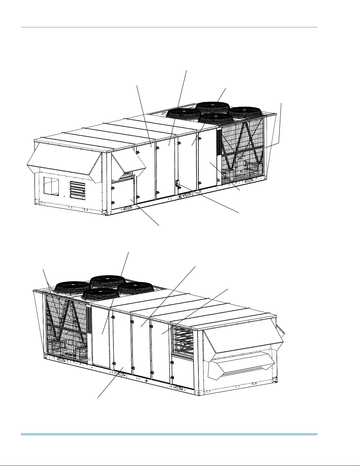
1 COMPONENT LOCATION . . . . . . . . . . . . . . . . . . . . . . . 6
2 TYPICAL RIGGING . . . . . . . . . . . . . . . . . . . . . . . . . . . 10
3 CENTER OF GRAVITY . . . . . . . . . . . . . . . . . . . . . . . . 11
4 RECOMMENDED DRAIN PIPING . . . . . . . . . . . . . . . . 14
5 TYPICAL THERMOSTAT WIRING . . . . . . . . . . . . . . . 14
6 TYPICAL GAS PIPING CONNECTION . . . . . . . . . . . . 16
7 VENT AND COMBUSTION AIR HOODS . . . . . . . . . . . 17
8 CLEARANCES . . . . . . . . . . . . . . . . . . . . . . . . . . . . . . . 17
9 HOT WATER PIPING CROSS-SECTION . . . . . . . . . . 19
10 STEAM PIPING CROSS-SECTION . . . . . . . . . . . . . . . 19
11 BOTTOM SUPPLY AND RETURN . . . . . . . . . . . . . . . 21
12 END RETURN, BOTTOM SUPPLY . . . . . . . . . . . . . . . 22
13 BOTTOM RETURN, FRONT & REAR SUPPLY . . . . . 23
14 END RETURN, FRONT & REAR SUPPLY . . . . . . . . . 24
15 FIELD INSTALLED DISCONNECT . . . . . . . . . . . . . . . 43
16 40 TON CONDENSER DETAIL . . . . . . . . . . . . . . . . . . 43
17 PARTIAL ROOF CURB MODEL 1RC0455P . . . . . . . . 44
18 ALTITUDE/TEMPERATURE CONVERSION
FACTOR . . . . . . . . . . . . . . . . . . . . . . . . . . . . . . . . . . . 46
19 FAN PERFORMANCE - 25 TON . . . . . . . . . . . . . . . . . 48
20 FAN PERFORMANCE - 30 TON . . . . . . . . . . . . . . . . . 50
21 FAN PERFORMANCE - 40 TON . . . . . . . . . . . . . . . . . 52
22 POWER EXHAUST - ONE FORWARD CURVE FAN
- 25 TONS . . . . . . . . . . . . . . . . . . . . . . . . . . . . . . . . . . 56
23 POWER EXHAUST - TWO FORWARD CURVED FANS
- 30 & 40 TONS . . . . . . . . . . . . . . . . . . . . . . . . . . . . . . 58
24 BELT TENSION ADJUSTMENT . . . . . . . . . . . . . . . . . 59
25 TYPICAL GAS VALVES . . . . . . . . . . . . . . . . . . . . . . . . 65
26 TYPICAL FLAME APPEARANCE . . . . . . . . . . . . . . . . 66
27 HOT WATER COIL - 25 & 30 TON, 1 ROW,
AT 10 GPM . . . . . . . . . . . . . . . . . . . . . . . . . . . . . . . . . 70
28 HOT WATER COIL - 25 & 30 TON, 1 ROW,
AT 20 GPM . . . . . . . . . . . . . . . . . . . . . . . . . . . . . . . . . 70
29 HOT WATER COIL - 25 & 30 TON, 1 ROW,
AT 30 GPM . . . . . . . . . . . . . . . . . . . . . . . . . . . . . . . . . 71
30 HOT WATER COIL - 25 & 30 TON, 1 ROW,
AT 40 GPM . . . . . . . . . . . . . . . . . . . . . . . . . . . . . . . . . 71
31 HOT WATER COIL - 25 & 30 TON, 2 ROW,
AT 60 GPM . . . . . . . . . . . . . . . . . . . . . . . . . . . . . . . . . 72
32 HOT WATER COIL - 25 & 30 TON, 2 ROW,
AT 80 GPM . . . . . . . . . . . . . . . . . . . . . . . . . . . . . . . . . 72
33 HOT WATER COIL - 40 TON, 1 ROW, AT 10 GPM . . 73
34 HOT WATER COIL - 40 TON, 1 ROW, AT 20 GPM . . 73
35 HOT WATER COIL - 40 TON, 1 ROW, AT 30 GPM . . 74
36 HOT WATER COIL - 40 TON, 1 ROW, AT 40 GPM . . 74
37 HOT WATER COIL - 40 TON, 2 ROW, AT 20 GPM . . 75
38 HOT WATER COIL - 40 TON, 2 ROW, AT 40 GPM . . 75
39 HOT WATER COIL - 40 TON, 2 ROW, AT 60 GPM . . 76
40 HOT WATER COIL - 40 TON, 2 ROW, AT 80 GPM . . 76
41 STEAM COIL - 25 & 30 TON (1 ROW) . . . . . . . . . . . . 77
42 STEAM COIL - 40 TON (1 ROW) . . . . . . . . . . . . . . . . 77
43 TYPICAL CONTROL WIRING . . . . . . . . . . . . . . . . . . . 78
44 LEGEND . . . . . . . . . . . . . . . . . . . . . . . . . . . . . . . . . . . 79
45 TYPICAL 25 TON POWER WIRING . . . . . . . . . . . . . . 80
46 TYPICAL STANDARD GAS HEAT WIRING . . . . . . . . 81
47 TYPICAL MODULATING GAS HEAT WIRING . . . . . . 82
48 TYPICAL FLUE BAFFLE . . . . . . . . . . . . . . . . . . . . . . . 85
49 25 TON CHARGING CURVE . . . . . . . . . . . . . . . . . . . . 86
50 30 TON CHARGING CURVE . . . . . . . . . . . . . . . . . . . . 87
51 40 TON CHARGING CURVE . . . . . . . . . . . . . . . . . . . . 88
52 PRESSURE DROP DRY EVAPORATOR COIL VS
SUPPLY AIR CFM - 25 TON . . . . . . . . . . . . . . . . . . . . 89
53 PRESSURE DROP DRY EVAPORATOR COIL VS
SUPPLY AIR CFM - 30 TON . . . . . . . . . . . . . . . . . . . . 90
54 PRESSURE DROP DRY EVAPORATOR COIL VS
SUPPLY AIR CFM - 40 TON . . . . . . . . . . . . . . . . . . . . 91
55 R-410A QUICK REFERENCE GUIDE . . . . . . . . . . . . . 92
Johnson Controls Unitary Products 3

882108-YIM-B-1012
LIST OF TABLES
Tbl. # Pg. #
1 COOLING & ELECTRICAL APPLICATION . . . . . . . . . 8
2 COOLING & ELEC. APP. LIMITATIONS . . . . . . . . . . . 8
3 STANDARD GAS HEATING CAPACITIES . . . . . . . . . 9
4 TEMPERATURE RISE . . . . . . . . . . . . . . . . . . . . . . . . . 9
5 MINIMUM HEATING CFM . . . . . . . . . . . . . . . . . . . . . . 9
6 MODULATING GAS HEATING CAPACITIES . . . . . . . 9
7 MODULATING HEAT . . . . . . . . . . . . . . . . . . . . . . . . . 10
8 UNIT WEIGHTS . . . . . . . . . . . . . . . . . . . . . . . . . . . . . 11
9 SUPPLY FAN MOTOR VFD WEIGHTS . . . . . . . . . . . 11
10 EXHAUST FAN MOTOR VFD WEIGHTS . . . . . . . . . 11
11 UNIT CORNERWEIGHT . . . . . . . . . . . . . . . . . . . . . . 12
12 UNIT CENTER OF GRAVITY . . . . . . . . . . . . . . . . . . . 12
13 CONTROL WIRE SIZES . . . . . . . . . . . . . . . . . . . . . . 14
14 PIPE SIZES . . . . . . . . . . . . . . . . . . . . . . . . . . . . . . . . 16
15 GENERAL PHYSICAL DATA . . . . . . . . . . . . . . . . . . . 25
16 REFRIGERANT FACTORY CHARGE R-410A . . . . . 26
17 ELECTRICAL DATA 25 TON BASIC UNIT R-410A . . 26
18 ELECTRICAL DATA 30 TON BASIC UNIT R-410A . . 27
19 ELECTRICAL DATA 40 TON BASIC UNIT R-410A . . 27
20 ELECTRICAL DATA 25 TON W/ELECTRIC HEAT
R-410A . . . . . . . . . . . . . . . . . . . . . . . . . . . . . . . . . . . . .28
21 ELECTRICAL DATA 30 TON W/ELECTRIC HEAT
R-410A . . . . . . . . . . . . . . . . . . . . . . . . . . . . . . . . . . . . .29
22 ELECTRICAL DATA 40 TON W/ELECTRIC HEAT
R-410A . . . . . . . . . . . . . . . . . . . . . . . . . . . . . . . . . . . . .30
23 ELECTRICAL DATA 25 TON W/POWER EXHAUST
R-410A . . . . . . . . . . . . . . . . . . . . . . . . . . . . . . . . . . . . .31
24 ELECTRICAL DATA 30 TON W/POWER EXHAUST
R-410A . . . . . . . . . . . . . . . . . . . . . . . . . . . . . . . . . . . . .32
25 ELECTRICAL DATA 40 TON W/POWER EXHAUST
R-410A . . . . . . . . . . . . . . . . . . . . . . . . . . . . . . . . . . . . .33
26 ELECTRICAL DATA 25 TON W/ELECTRIC HEAT
AND POWER EXHAUST R-410A . . . . . . . . . . . . . . . .34
27 ELECTRICAL DATA 30 TON W/ELECTRIC HEAT
AND POWER EXHAUST R-410A . . . . . . . . . . . . . . . .37
28 ELECTRICAL DATA 40 TON W/ELECTRIC HEAT AND
POWER EXHAUST R-410A . . . . . . . . . . . . . . . . . . . .40
29 ALTITUDE CORRECTION FACTORS . . . . . . . . . . . . 45
Tbl. # Pg. #
30 FAN PERFORMANCE - 25 TON . . . . . . . . . . . . . . . . . 47
31 FAN PERFORMANCE - 30 TON . . . . . . . . . . . . . . . . . 49
32 FAN PERFORMANCE - 40 TON . . . . . . . . . . . . . . . . . 51
33 COMPONENT STATIC RESISTANCE. . . . . . . . . . . . . 53
34 SUPPLY FAN MOTOR AND DRIVE DATA . . . . . . . . . 54
35 EXHAUST FAN DRIVE DATA . . . . . . . . . . . . . . . . . . . 54
36 POWER EXHAUST - ONE FORWARD CURVED
FAN 25 TON . . . . . . . . . . . . . . . . . . . . . . . . . . . . . . . . 55
37 POWER EXHAUST - TWO FORWARD CURVED
FANS - 30 & 40 TON . . . . . . . . . . . . . . . . . . . . . . . . . . 57
38 BELT ADJUSTMENT . . . . . . . . . . . . . . . . . . . . . . . . . . 60
39 BLOWER SPEED RATE OF CHANGE . . . . . . . . . . . . 61
40 25 TON DRIVE ADJUSTMENT . . . . . . . . . . . . . . . . . . 62
41 30 TON DRIVE ADJUSTMENT . . . . . . . . . . . . . . . . . . 62
42 40 TON DRIVE ADJUSTMENT . . . . . . . . . . . . . . . . . . 63
43 DRIVE ADJUSTMENT FOR POWER EXHAUST
- 25 TON . . . . . . . . . . . . . . . . . . . . . . . . . . . . . . . . . . . 63
44 DRIVE ADJUSTMENT FOR POWER EXHAUST
- 30 & 40 TON . . . . . . . . . . . . . . . . . . . . . . . . . . . . . . . 64
45 GAS RATE - CUBIC FEET PER HOUR . . . . . . . . . . . . 66
46 STEAM COIL (1 ROW, 40 TON) . . . . . . . . . . . . . . . . . 67
47 STATIC RESISTANCE STEAM COIL (25 & 30 TON) . 67
48 STEAM COIL (1 ROW, 25 & 30 TON) . . . . . . . . . . . . . 67
49 STATIC RESISTANCE STEAM COIL (40 TON) . . . . . 67
50 HOT WATER COIL (1 ROW 25 & 30 TON) . . . . . . . . . 67
51 HOT WATER COIL (1 ROW, 40 TON) . . . . . . . . . . . . . 68
52 WATER PRESSURE DROP (1 ROW, 25 & 30 TON) . 68
53 WATER PRESSURE DROP (1 ROW, 40 TONS) . . . . 68
54 HOT WATER COIL (2 ROW, 25 & 30 TON) . . . . . . . . 68
55 WATER PRESSURE DROP (2 ROW, 25 & 30 TON) . 69
56 WATER PRESSURE DROP (2 ROW, 40 TON) . . . . . . 69
57 STATIC RESISTANCE HOT WATER COIL
(25 & 30 TON) . . . . . . . . . . . . . . . . . . . . . . . . . . . . . . . 69
58 STATIC RESISTANCE HOT WATER COIL
(40 TON) . . . . . . . . . . . . . . . . . . . . . . . . . . . . . . . . . . .69
59 INDOOR BLOWER BEARING LUBRICATION
SCHEDULE . . . . . . . . . . . . . . . . . . . . . . . . . . . . . . . . . 84
4 Johnson Controls Unitary Products
NOMENCLATURE
R
A = 1,3,5,7
OPTIONS
ADDITIONAL
CONFIGURATION
Cu/Cu Condenser Coil
Cu/Cu Evaporator Coil
123 4
14
D
13
A
12
C
CONTROL
Exhaust VFD (Customer)
(see note 3)
* Premium Cabinet (6 doors)
* Standard Cabinet (4 doors)
* Drain Pan - powder coat
* Drain Pan - stainless steel
D = SYNTHESYS CONTROL
E = SYNTHESYS CONTROL,
DISC., 110V OUTLET
110V OUTLET
F = SYNTHESYS, DISC.
J = SIMPLICITY CONTROL,
H = SIMPLICITY CONTROL
I = SIMPLICITY CONTROL, DISC
®
®
®
DISC, 110V OUTLET
DISC, NO 110V OUTLET
K = SIMPLICITY CONTROL W/SIMPLICITY LINC
DISC, NO 110V OUTLET
L = SIMPLICITY CONTROL W/SIMPLICITY LINC
M = SIMPLICITY CONTROL W/SIMPLICITY LINC
N = YCCS CONTROL
ECONOMIZER
P = YCCS CONTROL W/DISC., 110V OUTLET
Q = YCCS ZONING CONTROL
R = YCCS ZONING CONTROL W/DISC.,
110V OUTLET
S = YCCS-VAV CONTROL
T = YCCS-VAV CONTROL W/DISC.,
110V OUTLET
C, = DRY BULB ENTH Low leak type
B, = SINGLE ENTH Low leak type
D = MANUAL Low leak (Not w/PE)
A = DUAL ENTH Low leak type
H = DRY BULB Std type
F = DUAL ENTH Std type
G = SINGLE ENTH Std type
E = NONE
(See note 5)
EXHAUST
B = 1, 3 K = 2, 6 T = A, 4
A = BARO J = 2, 5 S = A, 3
C = 1, 4 L = 2, 7 U = A, 5
D = 1, 5 M = 2, 8 V = A, 6
E = 1, 6 N = NONE W = A, 7
882108-YIM-B-1012
3 = 13,000 CFM ERV
9 = Non Std Config
I = 2, 4 R = 2, 0 2 = 8,000 CFM ERV
H = 2, 3 Q = 2, 9 Z = A, 0
F = 1, 7 O = 1, 9 X = A, 8
G = 1, 8 P = 1, 0 Y = A, 9
7 = 10 HP HI-EFF
MOTOR
Motor
Power Exhaust
1 = MODULATING DAMPERS A = VFD MODULATING
2 = NON-MOD. (ON/OFF)
0 = 5 HP HI-EFF (25T Only)
8 = 15 HP HI-EFF (Except 25 Ton)
-EFF
6 = 7.5 HP HI
11
A
10
A
9
1
8
B
7
4
6
3
5
N
4
A
3
3
2
3
1
Z
FILTERS
A = STAND.
B = 65%
VOLTAGE
2 = 208/230-60
3 = 380-60
PACKAGE
Z = York Brand R-410A
C = 95%
D = 2" HI-EFF
1. 108KW not available with 208/230V.
NOTES:
(See note 4)
(30T/40T)
4 = 460-60
ID BLOWER
5 = 575-60
7 = 380/415-50
BASIC UNIT
GENERATION
2 = 25 TON
minimum efficiency regulations mandated
in Canadian Energy Efficiency Regulations.
only; VFD will be customer supplied and
2. Standard efficiency motor meets Canadian
A = A, F, I L = D, G, J W = D, E, J
field installed. If VFD Exh is also
3. (VFD-CUSTOMER) = Wired for VFD
E = A, E, H P = B, G, J 2 = B, E, J
D = A, G, J O = B, G, I Z = B, E, I
C = A, F, J N = B, F, J Y = B, E, H
B = A, G, I M = B, F, I X = D, F, H
CONFIGURATION
3 = 30 TON
4 = 40 TON
A = 1,2 1 - BOTTOM RETURN
B = 1,4 2 - BOTTOM SUPPLY
specified, it will also be cust supplied.
G = A, E, J R = C, F, J 4 = C, E, H
F = A, E, I Q = C, F, I 3 = B, F, H
(5)
3 - END RETURN
C = 1,5
Contact engineering for
air foil applications.
available in end return configuration.
6. Air foil fan available on cooling only.
4. VAV ID Blower requires hot gas bypass .
5. Power exhaust and barometric relief not
9 = D, G, H
K = D, G, I V = D, E, I
J = D, F, J U = D, E, H 8 = C, F, H
I = D, F, I T = C, G, J 7 = C, E, J
H = A, F, H S = C, G, I 6 = C, E, I
D = 3,2 4 - REAR SUPPLY
Air Volume
a = CV
F = 3,5
E = 3,4 5 - FRONT SUPPLY
FRONT SUPPLY - COOLING ONLY
HOT WATER, STEAM & ELECTRIC HEAT -
BOTTOM SUPPLY ONLY
GAS HEAT - BOTTOM OR REAR SUPPLY ONLY
b = VAV (VFD-FACTORY INSTALLED)
Config
Z = 2,3,9,8
2 = 2,4,9,8
7 = 1,4,9,8
Y = 1,3,9,8
9 = Non-Std
R = 2,3,9,7
T = 2,4,9,7
Q = 1,3,9,7
L = 2,4,5,8
S = 1,4,9,7
K = 1,4,5,8
REFRIGERATION
D = 2,4,5,7
I = 1,3,5,8
B = 2,3,5,7
(3)
Fan (See note 6)
c = BYPASS FACTORY VFD
d = VAV (VFD-CUSTOMER)
J = 2,3,5,8
C = 1,4,5,7
g = AIR FOIL FAN [always Class II]
e = FORWARD CURVE FAN Class I
f = FORWARD CURVE FAN Class II
Condenser Coil Head Press. Ctrl.
Class I blower is limited to 15HP in 25/30Ton
Class I blower is limited to 20HP in 40Ton
Class II blowers are not HP limited
Blower Mount
HEAT SOURCE
W = HOT WATER COIL
C = COOLING ONLY
E = ELECTRIC HEAT
T = NATURAL GAS, MODULATING HEAT, SS *
N = NATURAL GAS
S = NATURAL GAS, SS HEAT EXCHANGER
D = NATURAL GAS, MODULATING HEAT*
HEAT EXCHANGE
(See note 4)
Piping
Evaporator Coil
2 = TECHNICOAT 8 = NO
1 = STANDARD 7 = YES
3 = STANDARD 4 = HOT GAS BYPASS
5 = STANDARD
9 = STD W/TECHNICOAT
(See note 2)
ID MOTOR
j = 2 inch deflection spring
h = Neoprene
i = 1 inch deflection spring
5 = 10 HI-EFF
6 = 15 HI-EFF
HEAT CAPACITY
3 = 267 MBH
5 = 533 MBH
8 = 800 MBH (40T ONLY)
X = STEAM COIL
4 = 40 KW
8 = 25 HI-EFF (Except 25T)
0 = 7.5 HI-EFF (25T Only)
7 = 20 HI-EFF
(1)
0 (ZERO) NO HEAT
1 = 108 KW
1 = 1 ROW
8 = 80 KW
1 = 1 ROW
2 = 2 ROW
Johnson Controls Unitary Products 5
882108-YIM-B-1012
EVAPORATOR COIL
AND DRAIN PAN ACCESS
REAR
LEFT END
FILTER DRIERS
FILTER ACCESS
POWER EXHAUST ACCESS
HEAT SECTION
POWER & CONTROL WIRING
COMPRESSOR ACCESS
HEAT SECTION
FRONT
EVAPORATOR COIL
AND DRAIN PAN ACCESS
OPTIONAL POWER
OUTLET (115V)
RIGHT
END
FILTER ACCESS
REAR
SUPPLY BLOWER & MOTOR
FIGURE 1 - COMPONENT LOCATION
6 Johnson Controls Unitary Products
GENERAL
York Model Z42/Z33/Z34 units are single package cooling
only or cooling with gas, electric, hot water or steam heating
designed for outdoor installation on a rooftop and for non-residential use.
The units are completely assembled on rigid, permanently
attached base rails. All piping, refrigerant charge, and electrical wiring is factory installed and tested. The units require
electric power, gas, steam, or hot water connections and duct
connections. Gas fired units also require installation of a flue
gas outlet hood.
Reference R-410A Quick Reference Guide, Figure 55 for
R-410A Refrigerant information.
SAFETY CONSIDERATIONS
NOTES, CAUTIONS AND WARNINGS
882108-YIM-B-1012
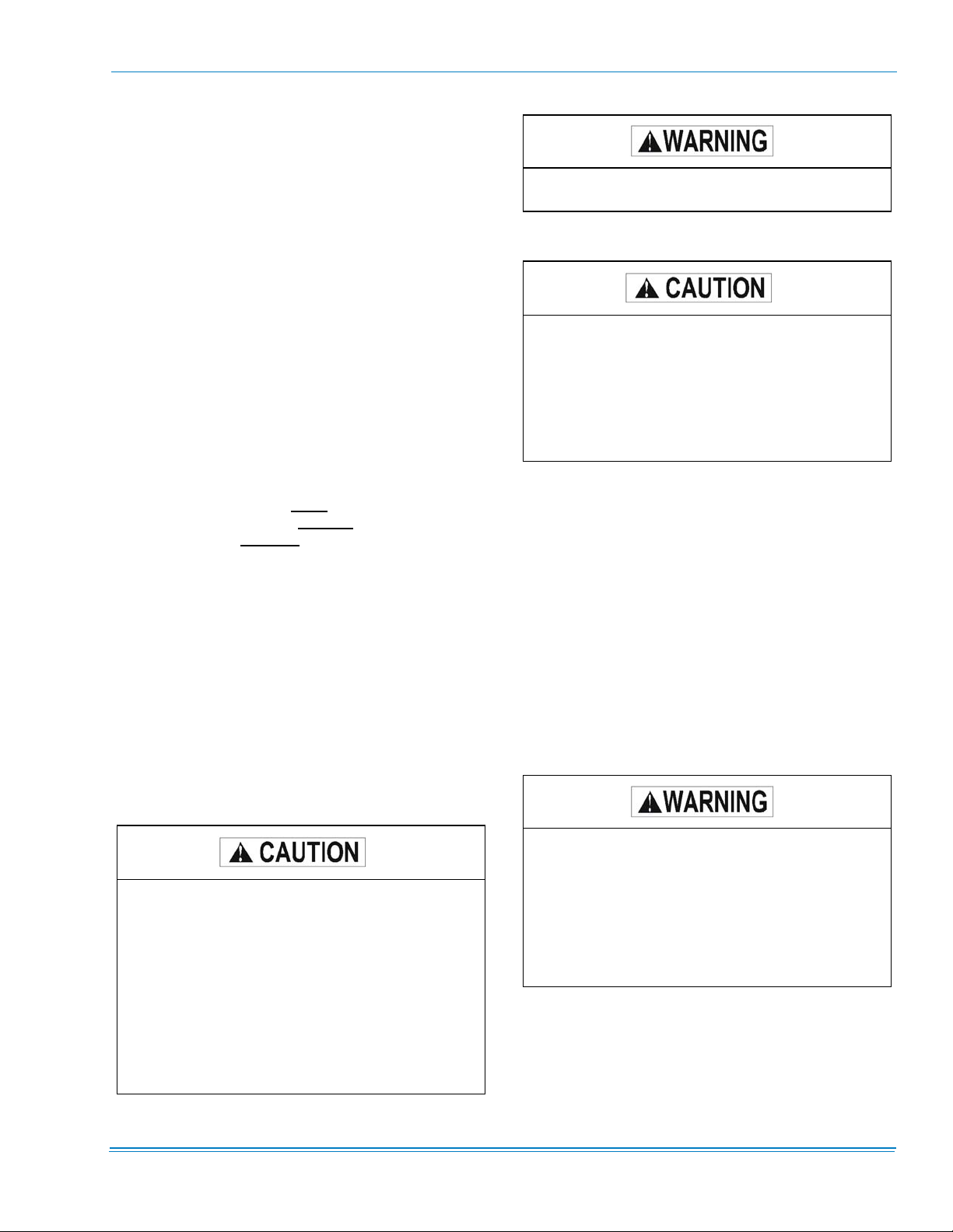
This Furnace is not to be used for temporary heating of buildings or structures under construction.
ALL MODELS
This system uses R-410A Refrigerant which operates at higher pressures than R-22. No other
refrigerant may be used in this system. Gage sets,
hoses, refrigerant containers and recovery systems must be designed to handle R-410A. If you
are unsure, consult the equipment manufacturer.
Failure to use R-410A compatible servicing equipment may result in property damage or injury.
Installer should pay particular attention to the words: NOTE,
CAUTION, and WARNING.
make the installation easier.
equipment damage.
personal injury and/or equipment damage may result if installation procedure is not handled properly.
Warnings are given to alert installer that
Notes are intended to clarify or
Cautions are given to prevent
GAS FIRED MODELS
DO NOT store or use gasoline or other flammable vapors and
liquids in the vicinity of this or any other appliance.
WHAT TO DO IF YOU SMELL GAS
Do not try to light any appliance. Do not touch any electrical
switch. Do not use any phone in your building. Immediately
call your gas supplier from a neighbor’s phone. Follow the
gas supplier’s instructions. If you cannot reach your gas sup-
plier, call the fire department.
The furnace and its individual shut-off valve must
be disconnected from the gas supply piping system during any pressure testing of that system at
test pressures in excess of 0.5 psig. Pressures
greater than 0.5 will cause gas valve damage
resulting in a hazardous condition. If gas valve is
subjected to a pressure greater than 0.5 psig, it
must be replaced. The furnace must be isolated
from the gas supply piping system by closing its
individual manual shut-off valve during any pressure testing of that system at test pressures equal
to or less than 0.5 psig.
Installation and servicing of air conditioning equipment can
be hazardous due to system pressure and electrical components. Only trained and qualified service personnel should
install, repair or service air conditioning equipment.
Untrained personnel can perform basic maintenance functions of cleaning coils and filters and replacing filters. All other
operations should be performed by trained service personnel.
When working on air conditioning equipment, observe precautions in the literature, tags and labels attached to the unit
and other safety precautions that may apply.
Follow all safety codes, including ANSI Z223.1-Latest Edition: wear safety glasses and work gloves; use quenching
cloth for unbrazing operations; have fire extinguisher avail-
able for all brazing operations.
Before performing service or maintenance operations on unit, turn off main power switch to unit.
Electrical shock could cause personal injury.
Improper installation, adjustment, alteration, service or maintenance can cause injury or property
damage. Refer to this manual. For assistance or
additional information consult a qualified installer,
service agency or the gas supplier.
INSPECTION
As soon as a unit is received, it should be inspected for possible damage during transit. If damage is evident, the extent of
damage should be noted on the carrier’s freight bill. A separate request for inspection by the carrier’s agent should be
made in writing.
Johnson Controls Unitary Products 7
882108-YIM-B-1012
REFERENCE
Additional information is available in the following reference
form:
• 246837 - Technical Guide
APPROVALS
Designed certified by CSA, ETL, CETL as follows:
1. For use as a forced air furnace with cooling unit (gas
heat models).
2. For outdoor installation only.
3. For installation on combustible material and may be
installed directly on combustible flooring or Class A,
Class B or Class C roof covering materials.
4. For use with natural gas (convertible to LP with kit).
Not suitable for use with conventional venting systems.
INSTALLATION
PRECEDING INSTALLATION
If a factory option convenience outlet is installed, the weatherproof outlet cover must be field installed. The cover shall be
located in the unit control box. To install the cover, remove
the shipping label covering the convenience outlet, follow the
instructions on the back of the weatherproof cover box, and
attach the cover to the unit using the (4) screws provided.
After installation, gas fired units must be adjusted to obtain a
temperature rise within the range specified on the unit rating
plate.
If components are to be added to a unit to meet local codes,
they are to be installed at the contractor's and/or the customer's expense.
Size of unit for proposed installation should be based on heat
loss / heat gain calculation made according to the methods of
the Air Conditioning Contractors of America (ACCA).
LOCATION
Use the following guidelines to select a suitable location for
these units:
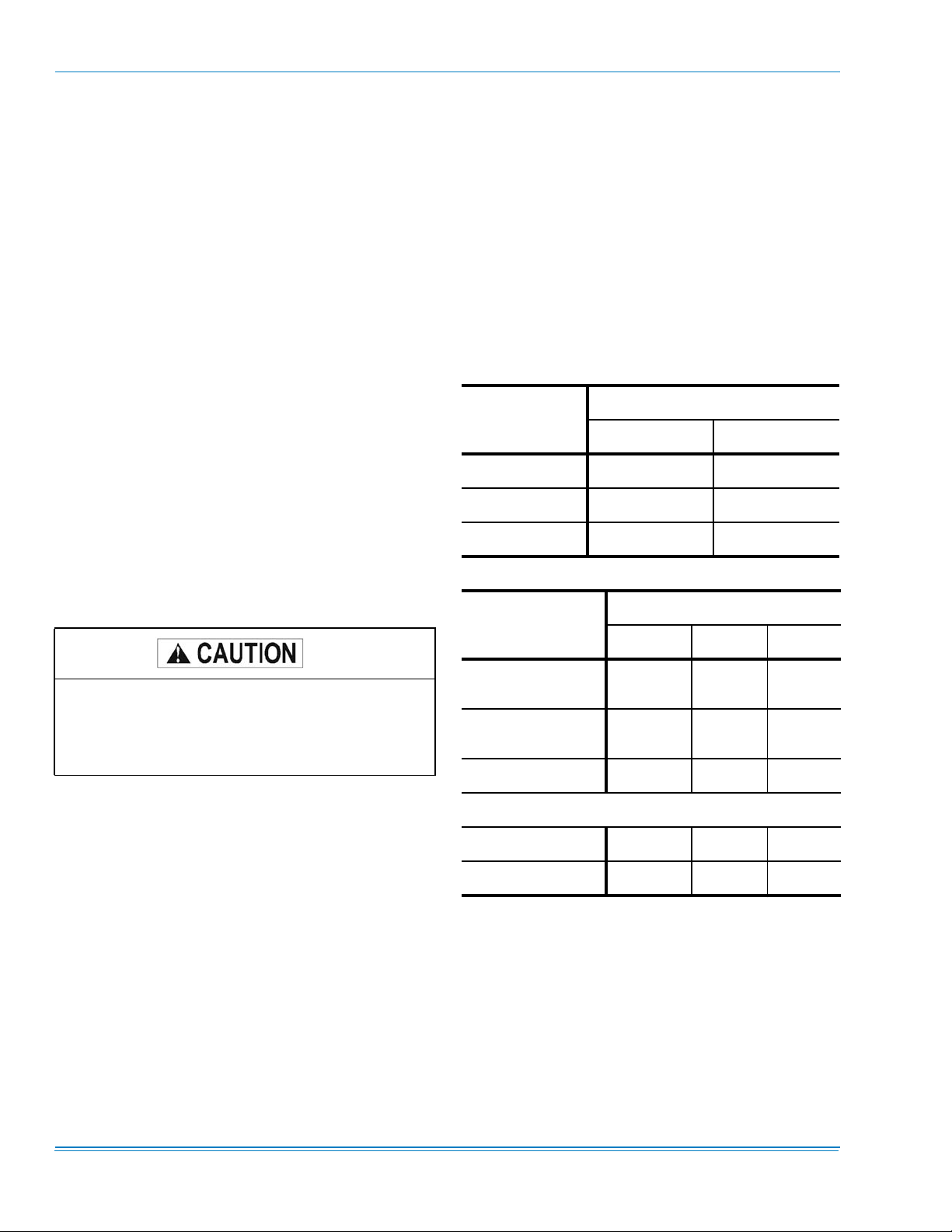
TABLE 1: COOLING & ELECTRICAL APPLICATION
UNIT POWER
SUPPLY
575-3-60 540 630
208/230-3-60 187 252
460-3-60 432 504
VOLTAGE VARIATIONS
MIN. VOLTS MAX VOLTS
TABLE 2: COOLING & ELEC. APP. LIMITATIONS
MODEL
LIMITATIONS
Z42 Z33 Z34
208/230-3-60 and 380/415-3-50 units with factory
installed Powered Convenience Outlet Option are
wired for 230v and 415v power supply respectively.
Change tap on transformer for 208-3-60 or 380-3-50
operation. See unit wiring diagram.
LIMITATIONS
The installation of this unit must conform to local building
codes, or in the absence of local codes, with ANSI Z223.1
Natural Fuel Gas Code and /or CAN/CGA B149 installation
codes.
In U.S.A.:
1. National Electrical Code ANSI/NFPA No. 70-Latest Edition.
2. National Fuel Gas Code Z223.1-Latest Edition.
3. Gas-Fired Central Furnace Standard ANSI Z21.47-Latest Edition.
4. Local gas utility requirements.
Refer to Table 1 for Cooling and Electrical Application Data
and to Table 2 for Gas Heat Application Data.
Supply Air CFM
(min./max)
Entering Wet Bulb
Temp (F°) (min./max)
Ambient Temp 40/125 40/125 40/125
Min. Air Temperature on Gas Fired Heat Exchangers (°F)
Aluminized 25 25 25
Stainless 000
6,00012,500
57/75 57/75 57/75
6,000-
15,000
8,000-
20,000
1. Unit is designed for outdoor installation only.
2. Condenser coils must have an unlimited supply of air.
Where a choice of location is possible, position the unit
on either north or east side of building.
3. Suitable for roof mount on curb.
4. Roof structures must be able to support the weight of the
unit and its accessories. Unit must be installed on a solid
level roof curb or appropriate angle iron frame.
5. Maintain level tolerance to 3/4 inches across width and 2
inches along length.
8 Johnson Controls Unitary Products
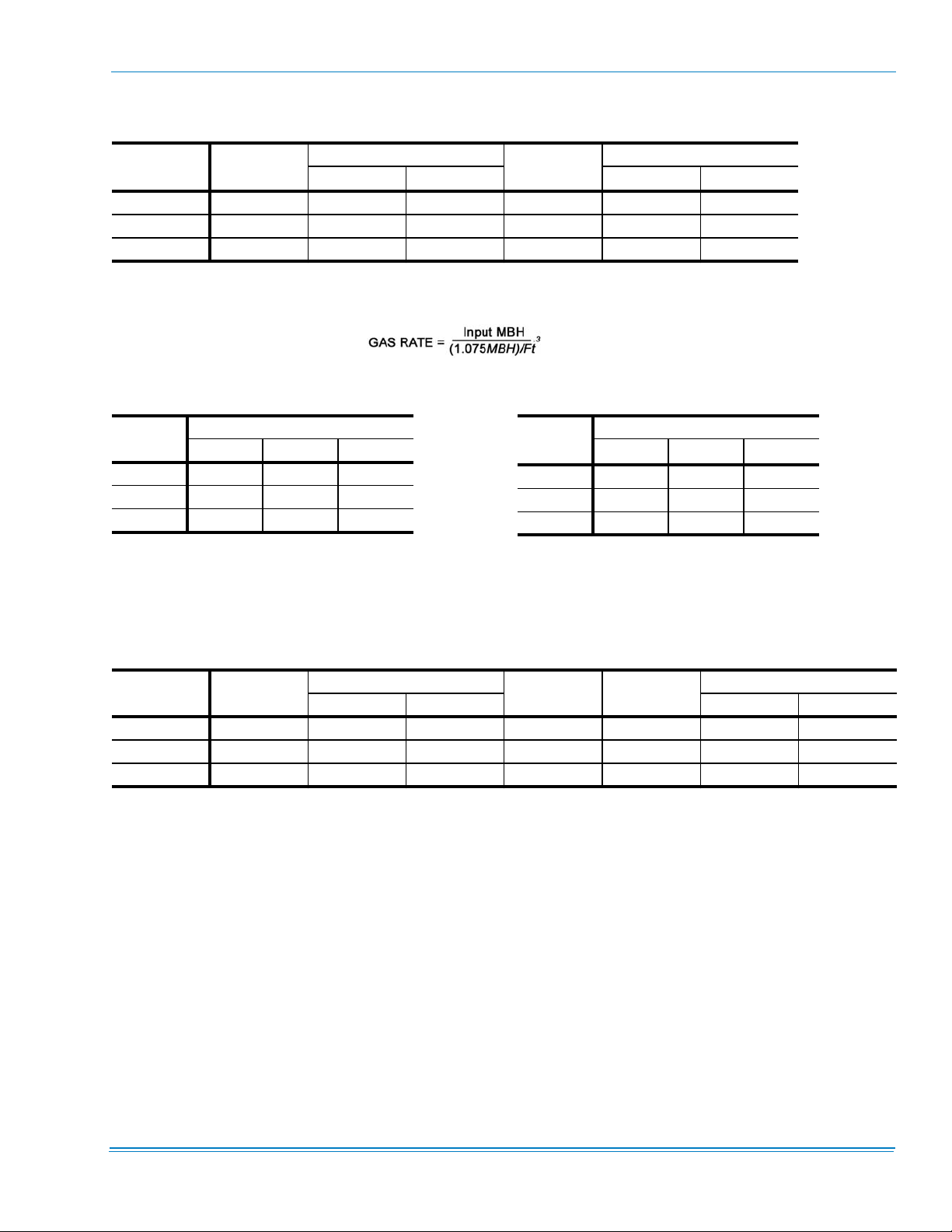
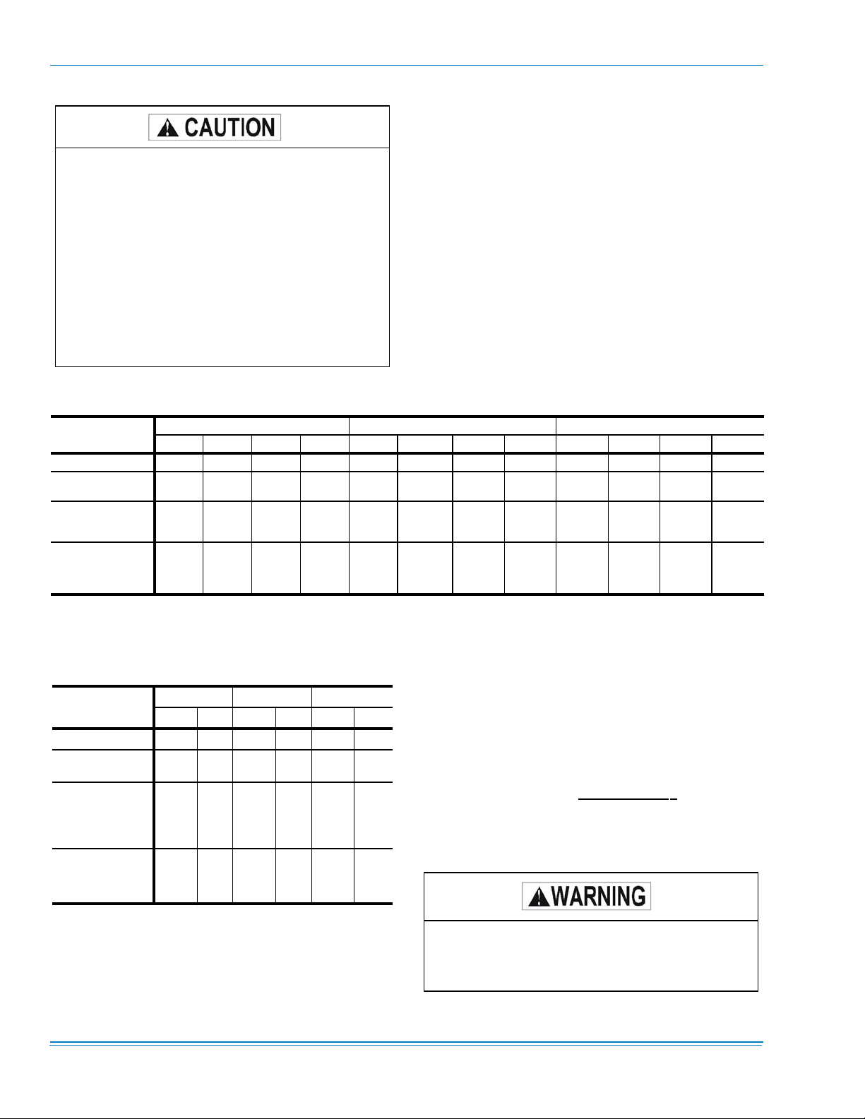
TABLE 3: STANDARD GAS HEATING CAPACITIES
GAS HEAT
OPTION
AVAILABLE ON
MODELS
INPUT CAPACITY (MBH)
1ST STAGE TOTAL 1ST STAGE TOTAL
1
N3 Z42/Z33/Z34 267 267 213 247 247
N5 Z42/Z33/Z34 267 533 426 247 495
N8 Z34 ONLY 267
1.
Heating capacity is only staged on CV models. VAV models use only one stage at full capacity.
2.
Blower motor heat not included.
3.
Based on a heat content of 1075 Btu/Ft.
4.
Unit Control Board with 3 heating outputs only. For all other Unit Control Boards the 1st Stage is 533 MBH.
4
3
800 638 247 742
TABLE 4: TEMPERATURE RISE
O
UTPUT
CAPACITY
(MBH)
2
G
AS RATE, CU. FT./HR.
TABLE 5: MINIMUM HEATING CFM
882108-YIM-B-1012
3
TON
123
MODULES
25 5-35 25-55 30 5-35 20-50 40 5-30 10-45 25-55
TABLE 6: MODULATING GAS HEATING CAPACITIES
GAS HEAT OPTION
2
D3
2
D5
2
D8
1.
Output Capacity at Full Fire.
2.
Modulating Gas Heat available on CV models only.
AVAILABLE ON
MODELS
Z42/Z33/Z34 69 267 6 213 64 247
Z42/Z33/Z34 69 533 12 426 64 495
Z34 ONLY 69 800 17 638 64 744
INPUT CAPACITY (MBH)
INIMUM MAXIMUM MINIMUM MAXIMUM
M
TON
1
1
MODULES
23
25 6,000 7,183 30 6,000 7,901 40 8,000 8,779 13,169
1.
Calculated minimum CFM for maximum heat
rise is 5,644 for 25/30T and 6,584 for 40T, 1
module.
AS RATE, CU. FT./HR.
STEPS
O
UTPUT CAPACITY
(MBH)
1
G
Johnson Controls Unitary Products 9
882108-YIM-B-1012
TABLE 7: MODULATING HEAT
STAGES OF GAS CONTROL (% OF FULL HEAT OUTPUT)
AS HEAT OPTION AVAILABLE ON MODELS STEP INPUT OUTPUT % OF TOTAL OUTPUT
G
1 69,333 55,466 26%
D3
(Turn down ratio
3.8 to 1)
D5
(Turn down ratio
7.7 to 1)
D8
(Turn down ratio
11.5 to 1)
Z42, Z33, Z34
Z42, Z33, Z34
Z34 Only
2 106,666 85,333 40%
3 165,332 132,266 62%
4 202,665 162,132 76%
5 229,332 183,466 86%
6 266,666 213,333 100%
1 69,333 55,466 13%
2 106,666 85,333 20%
3 165,332 132,266 31%
4 202,665 162,132 38%
5 229,332 183,466 43%
6 266,666 213,333 50%
7 325,331 260,265 61%
8 362,664 290,132 68%
9 389,331 311,465 73%
10 426,664 341,331 80%
11 495,997 396,798 93%
12 533,330 426,664 100%
1 69,333 55,466 9%
2 106,666 85,333 13%
3 165,332 132,266 21%
4 202,665 162,132 25%
5 229,332 183,466 29%
6 266,666 213,333 33%
7 325,331 260,265 41%
8 362,664 290,132 45%
9 389,331 311,465 49%
10 426,664 341,331 53%
11 495,997 396,798 62%
12 533,330 426,664 67%
13 586,663 469,330 73%
14 655,996 524,797 82%
15 693,329 554,663 87%
16 762,662 610,130 95%
17 799,995 639,996 100%
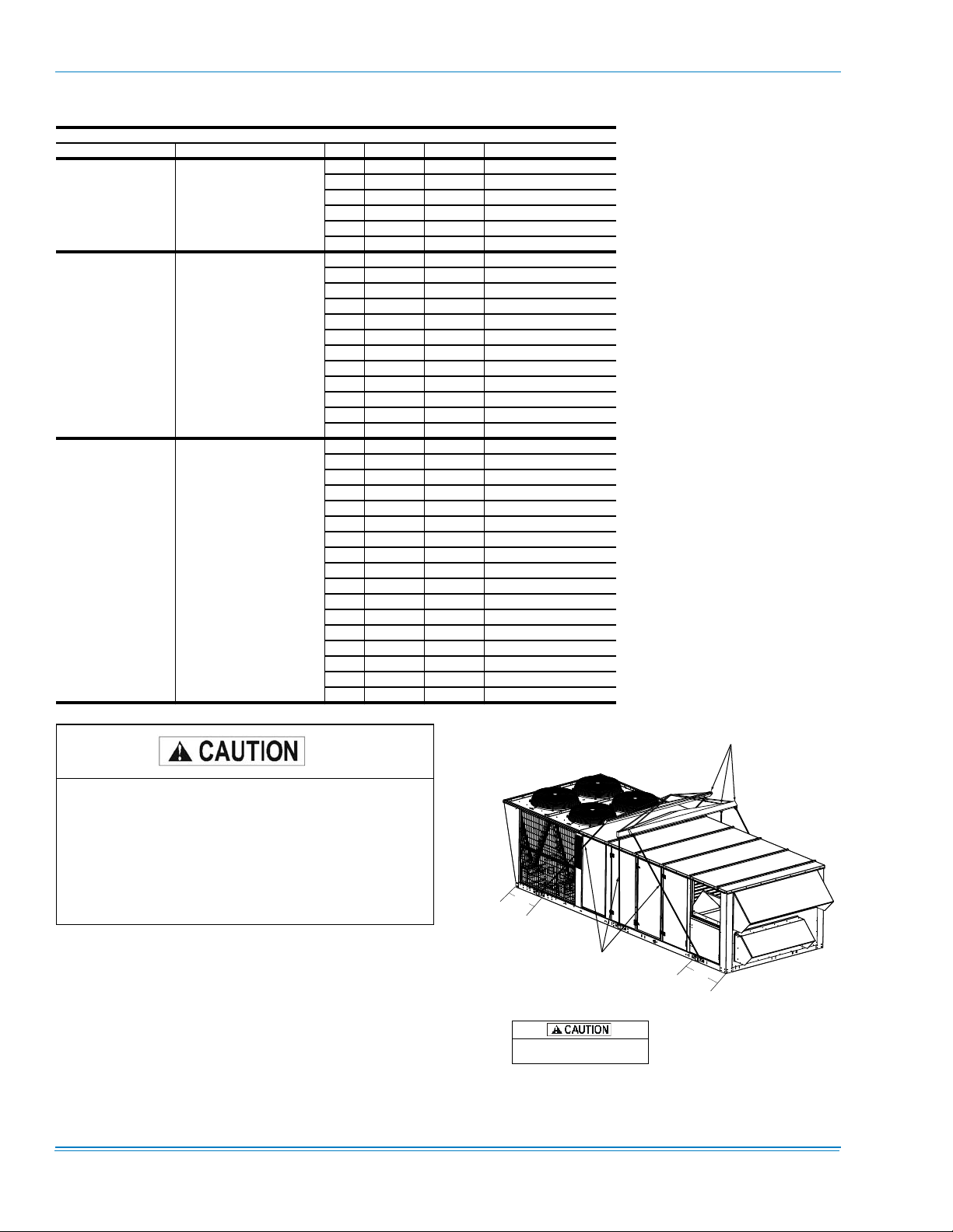
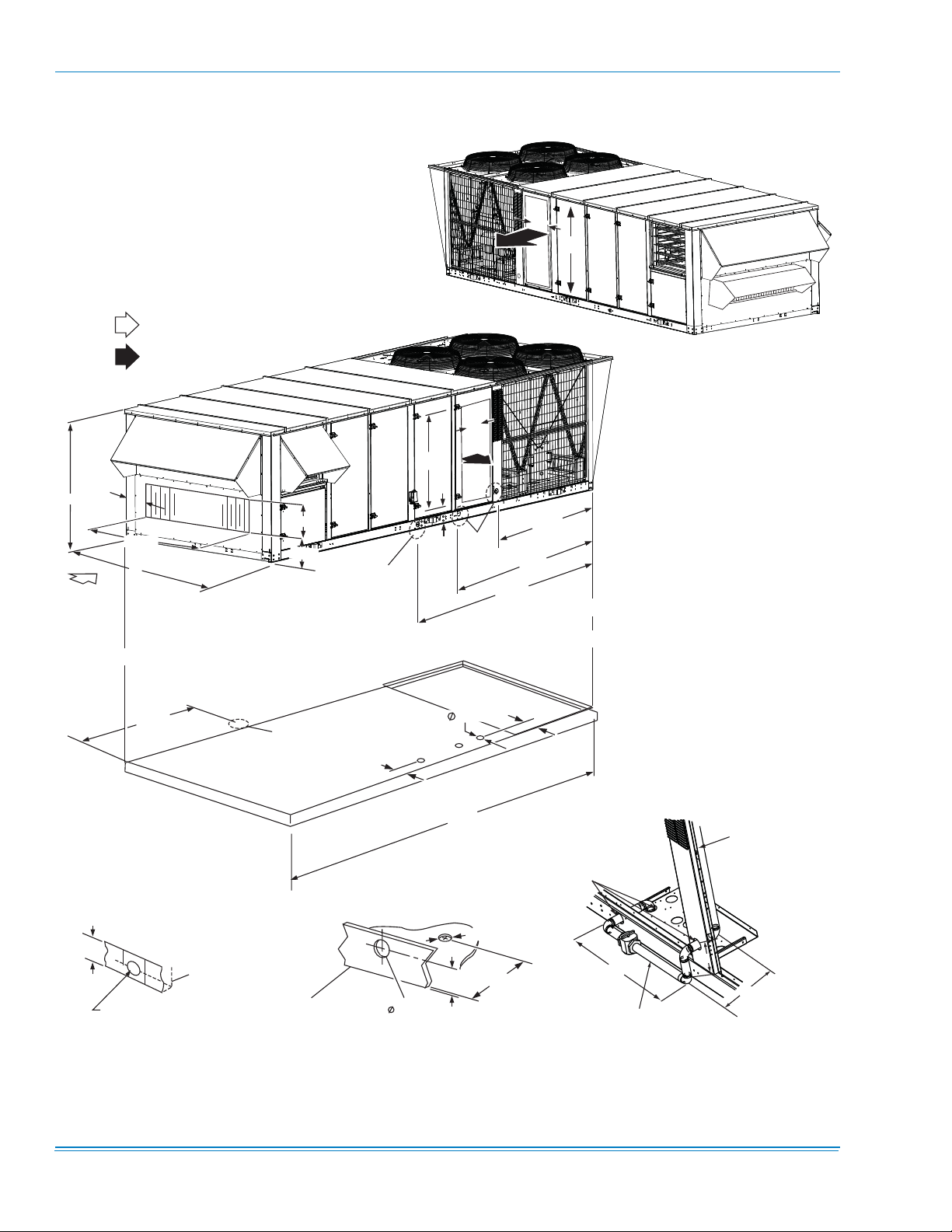
SPREADER BARS
(3 PLACES)
If a unit is to be installed on a roof curb other than a
York roof curb, gasketing must be applied to all surfaces that come in contact with the unit underside.
If a unit is to be installed on an angle iron frame it is
recommended that it be sized to allow the bottom
rail to overhang to facilitate installation of condensate drains (see Fig. 4).
RIGGING:
27”
CABLES
(1) RIG WITH SIX CABLES AND THREE SPREADER
BARS AT LEAST 98” ACROSS THE WIDTH OF THE UNIT.
(2) CENTER OF GRAVITY INCLUDES ECONOMIZER
AND POWER EXHAUST.
ALL PANELS MUST BE SECURED IN
PLACE WHEN THE UNIT IS LIFTED.
32”
FIGURE 2 - TYPICAL RIGGING
10 Johnson Controls Unitary Products
882108-YIM-B-1012
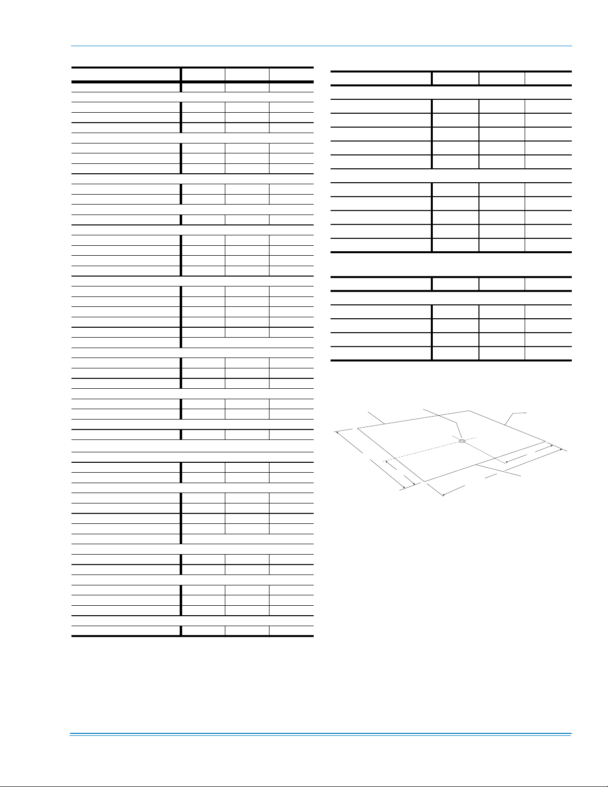
TABLE 8: UNIT WEIGHTS
COMPONENT 25 TON 30 TON 40 TON
Basic Unit 4410 4565 4845
Gas Heat
267 MBH 180 180 180
533 MBH 320 320 320
800 MBH - - 450
Electric Heat
40KW 40 40 40
80KW 105 105 105
108KW 110 110 110
Hot Water Heat
1 Row Coil 70 70 70
2 Row Coil 85 85 85
Steam Heat
1 Row Coil 85 85 85
Blower
Forward Curve Fan (Std Fan) 0 0 0
FC IGV 155 155 175
Air Foil Fan 135 135 155
AF IGV 155 155 180
Motor - Supply Fan
7.5hp 110 - 10hp 145 145 145
15hp 200 200 200
20hp 240 240 240
25hp - 300 300
Supply Fan Motor VFD See Table 9
Refrigeration
T-Coat Evap. 32 30 40
T-Coat cond. 32 30 40
Hot Gas Bypass 10 10 10
Low Ambient Head Pressure Control
208-230/380/460 5 5 5
575 25 25 25
Filters
6" Rigid 70 70 70
Exhaust
Exhaust Type
Barometric 45 65 65
Modulated 140 275 275
Exhaust Motor
5hp 80 80 80
7.5hp 110 110 110
10hp 145 145 145
15hp 200 200 200
Exhaust Motor VFD See Table 10
Economizer
Std. Econ. 235 235 235
Econ. w/ERV 50 50 50
Disconnect 15 15 15
110V outlet 55 55 55
Optilogic 20 20 20
Roof Curb
Partial Curb 415 415 415
1.
If ERV and Supply Fan VAV are selected, add the
weight of an Exhaust VFD, Table 9.
1
Control
TABLE 9: SUPPLY FAN MOTOR VFD WEIGHTS
Supply Fan Motor VFD 230V 460V 575V
W/O Bypass
7.5hp 60 25 30
10hp 60 25 30
15hp 75 50 60
20hp 75 50 60
25hp 115 50 60
W/Bypass
7.5hp 155 90 120
10hp 155 90 120
15hp 185 140 155
20hp 185 140 155
25hp 255 140 155
TABLE 10: EXHAUST FAN MOTOR VFD WEIGHTS
Exhaust Fan Motor 230V 460V 575V
W/O Bypass
5hp 15 10 20
7.5hp 50 15 20
10hp 50 15 20
15hp 65 40 50
NOTE: If the Millennium is VAV with ERV, add the
weight of an exhaust VFD - it will be in the unit.
.
REAR
B
92”
FIGURE 3 - CENTER OF GRAVITY
1.
Refer to Tables 11 and 12 for A, B, C, D and X and Y
data respectively.
CENTER OF
GRAVITY
Y
A
C
240”
RIGHT END
CONDENSER
COILS
D
X
FRONT
1
Johnson Controls Unitary Products 11
882108-YIM-B-1012
All panels must be secured in place when the unit
is lifted.
The condenser coils should be protected from
damage by the rigging cables with plywood or
other suitable material.
RIGGING AND HANDLING
This unit is not designed to be handled with a fork-truck.
Exercise care when moving the unit. Do not remove any
packaging until the unit is near the place of installation. Rig
the unit by attaching cable slings to the lifting lugs provided in
the unit base rails. Spreaders MUST be used across the top
of the unit. Refer to Figure 2.
An adhesive backed cover is provided over the
outside of the combustion air inlet opening on gas
• Rig with six cables and spread with three 98-inch
spreaders across width of unit.
fired units to prevent moisture from entering the
unit which could cause damage to electrical components. Allow this closure label to remain in place
until the combustion air hood is to be installed
(Refer to Figures 7).
• Refer to Tables 8 and 11 for unit weight.
• Center of gravity includes economizer, exhaust or return
air fan (Refer to Table 12).
TABLE 11: UNIT CORNERWEIGHT
UNIT
DESCRIPTION
Basic Unit 870 949 1352 1239 930 972 1360 1303 969 969 1454 1454
Basic Unit With
Economizer
Basic Unit With
Economizer and
Gas or Electric Heat
Basic Unit With
Economizer and
Gas or Electric Heat
and Power Exhaust
NOTES: Basic Unit = cooling only, 10hp FC fan.
+ Econ = +235lb
+ Heat = single stage gas, 180 lb
+ Power Exhaust = modulating 7.5hp
ABCDAB CDABCD
1018 1111 1313 1203 1076 1124 1328 1272 1058 1058 1482 1482
994 1084 1418 1300 1073 1073 1403 1403 1102 1055 1503 1570
1220 1275 1318 1262 1275 1275 1410 1410 1335 1278 1485 1551
TABLE 12: UNIT CENTER OF GRAVITY
MODEL
Basic Unit 99” 48” 100” 47” 96” 46"
Basic Unit /w
Econ.
Basic Unit /w
Econ. & Gas or
Elect. Heat,
Steam or Hot
Water Heat
Basic Unit /w
Econ. & Gas or
Elect. Heat, &
Power Exhaust
25 TON 30 TON 40 TON
XYXYXY
110” 48” 110” 47” 100” 46"
104” 48” 104” 46” 99” 45"
118” 47” 114” 46” 111” 45"
25 TON 30 TON 40 TON
CLEARANCES
All units require certain clearances for proper operation and
service. Installer must make provisions for adequate combustion and ventilation air in accordance with section 5.3, Air for
Combustion and Ventilation of the National Fuel Gas Code
ANSI Z223.1 or Sections 7.2, 7.3 or 7.4 of CAN/CGA B149
installation codes-Latest Edition and/or applicable provisions
of the local building codes.
required for combustible construction, servicing, and proper
unit operation.
Refer to Figure 8 for clearances
(COOLING OPERA TION) Do not permit overhanging structures or shrubs to obstruct condenser air
discharge outlet, combustion air inlet or vent outlets.
12 Johnson Controls Unitary Products
882108-YIM-B-1012
When the unit is equipped with power exhaust fans or return
air fan the return duct should have a 90 elbow before opening
to the building space to abate noise.
(GAS HEATING OPERATION)
Excessive exposure to contaminated combustion
air will result in safety and performance related
problems. To maintain combustion air quality, the
recommended source of combustion air is the outdoor air supply.
The outdoor air supplied for combustion should be
free from contaminants due to chemical exposure
that may be present from the following sources:
• Commercial buildings
• Indoor pools
• Laundry rooms
• Hobby or craft rooms
• Chemical storage areas
The following substances should be avoided to
maintain outdoor combustion air quality:
• Permanent wave solutions
• Chlorinated waxes and cleaners
• Chlorine based swimming pool cleaners
• Water softening chemicals
• De-icing salts or chemicals
• Carbon tetrachloride
• Halogen type refrigerants
• Cleaning solvents (such as perchloroethylene)
• Printing inks, paint removers, varnishes, etc.
• Hydrochloric acid
• Cements and glues
• Antistatic fabric softeners for clothes dryers
• Masonry acid washing materials
The supply and return air duct systems should be designed
for the CFM and static pressure requirements of the job. They
should NOT be sized to match the dimensions of the duct
connections on the unit.
If the unit is equipped with hot water or steam heat then the
supply air direction will be down only.
AIR HOODS FOR FIXED OUTSIDE AIR (UNITS WITH MANUAL ECONOMIZER)
These hoods are factory installed. The dampers may be
adjusted by loosening the thumb screw, turning the lever to
the desired position, and retightening the thumb screw.
AIR HOODS FOR ECONOMIZER
There are (3) economizer outside air intake hoods provided
with the unit. The hood on the end of the unit is factory
mounted. The (2) front and rear hoods are made operational
per the following instructions.
Remove the screws holding the economizer hood shipping
covers in place. Discard covers.
Rotate the hoods out (each hood is hinged in the lower corner). Secure the hoods with screws along the top and sides.
Apply a bead of RTV sealer along the edge of both hoods
and each pivot joint to prevent water leakage.
Seal any unused screw holes with RTV or by replacing the
screw.
AIR HOODS FOR EXHAUST AIR
When furnished, these hoods and dampers are factory
DUCTWORK
Ductwork should be designed and sized according to the
methods in Manual Q of the Air Conditioning Contractors of
America (ACCA).
A closed return duct system should be used. This will not pre-
clude use of economizers or outdoor fresh air intake. The
supply and return air duct connections at the unit should be
made with flexible joints to minimize noise.
Johnson Controls Unitary Products 13
installed.
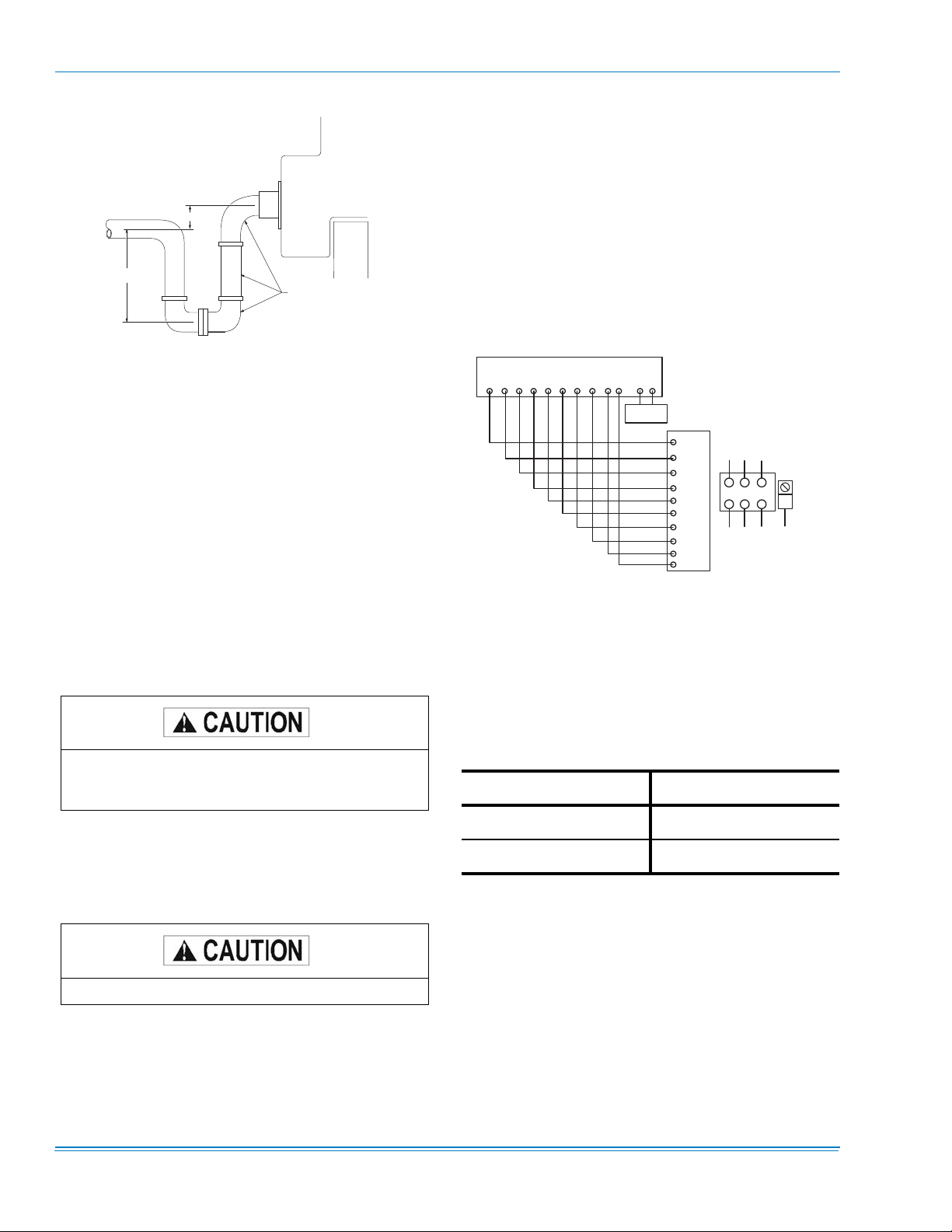
CONDENSATE DRAIN
There is one condensate drain connection. Trap the connection per Figure 4. The trap and drain lines should be protected from freezing.
Plumbing must conform to local codes. Use a sealing compound on male pipe threads. Install condensate drain lines
from the 1-1/2 inch NPT female connections on the unit to an
open drain.
882108-YIM-B-1012
D R A I N C O N N E C T I O N
F A C T O R Y I N S T A L L E D
H
FILTERS
U N I T B A S E
Y
R O O F
C U R B
O R
P E R I M E T E R
S U P P O R T
S T R U C T U R E
F I E L D S U P P L I E D
Throwaway or rigid filters are supplied with each unit. Filters
must always be installed ahead of evaporator coil and must
be kept clean or replaced with same size and type. Dirty filters will reduce the capacity of the unit and will result in
frosted coils or safety shutdown. Required filter sizes are
shown in Table 15. The unit should not be operated without
filters properly installed.
THERMOSTAT (CONSTANT VOLUME UNITS)
Y - M I N I M U M 2 "
H - 1 / 2 " P L U S T O T A L S T A T I C P R E S S U R E - M I N I M U M
FIGURE 4 - RECOMMENDED DRAIN PIPING
SERVICE ACCESS
Access to all serviceable components is provided by the following hinged doors:
• Furnace compartment
• Supply Air Fan compartment Evaporator Coil compartment (three doors)
• Filter compartment economizer compartment (two doors)
• Power Exhaust compartment (two doors)
• Main control panels (one door)
Refer to Figure 1 for location of these access panels.
Make sure that all screws and panel latches are
replaced and properly positioned on the unit to
maintain an air-tight seal.
T 7 3 0 0 T H E R M O S T A T S U B B A S E
R C G Y 1 Y 2 Y 3 Y 4 W 1 W 2 A 1 C T T
R E M O T E
2 T H O 4 7 0 2 2 2 4
S E N S O R
R
Y 1
G
Y 2
Y 3
Y 4
W 1
W 2
A 1
C
L 1
A
P O W E R S U P P L Y
P O W E R W I R I N G
L 2 L 3
T B 1
B
E Q U I P . G N D .
C
FIGURE 5 - TYPICAL THERMOSTAT WIRING
The thermostat, if used, should be located on an inside wall
approximately 56 inches above the floor where it will not be
subject to drafts, sun exposure or heat from electrical fixtures
or appliances. Follow manufacturer's instructions enclosed
with sensor for general installation procedure (See Figure 5).
Refer to Table 13 for control wire sizing and maximum length.
TABLE 13: CONTROL WIRE SIZES
WIRE SIZE MAXIMUM LENGTH
20 AWG 100 Feet
COMPRESSORS
18 AWG 150 Feet
Units are shipped with compressor mountings factoryadjusted and ready for operation.
DO NOT loosen compressor mounting bolts.
14 Johnson Controls Unitary Products
SPACE SENSOR (VARIABLE AIR VOLUME UNITS)
The space sensor, if used, should be located on an inside
wall approximately 56 inch above the floor where it will not be
subject to drafts, sun exposure or heat from electrical fixtures
or appliances. Follow manufacturer's instructions enclosed
with sensor for general installation procedure.
882108-YIM-B-1012
POWER AND CONTROL WIRING
Field wiring to the unit must conform to provisions of National
Electrical Code (NEC) ANSI / NFPA 70-Latest Edition and / or
local ordinances. The unit must be electrically grounded in
accordance with the NEC and / or local codes. Voltage tolerances which must be maintained at the compressor terminals
during starting and running conditions are indicated on the
unit Rating Plate and Table 1.
The internal wiring harnesses furnished with this unit are an
integral part of the design certified unit. Field alteration to
comply with electrical codes should not be required. If any of
the wire supplied with the unit must be replaced, replacement
wire must be of the type shown on the wiring diagram and the
same minimum gauge as the replaced wire.
Power supply to the unit must be NEC Class 1 and must
comply with all applicable codes. A disconnect switch must
be provided (factory option available). The switch must be
separate from all other circuits. Wire entry at knockout openings requires conduit fittings to comply with NEC and/or Local
Codes. Refer to Figures 11, 12, 13, and 14 for installation
location of openings.
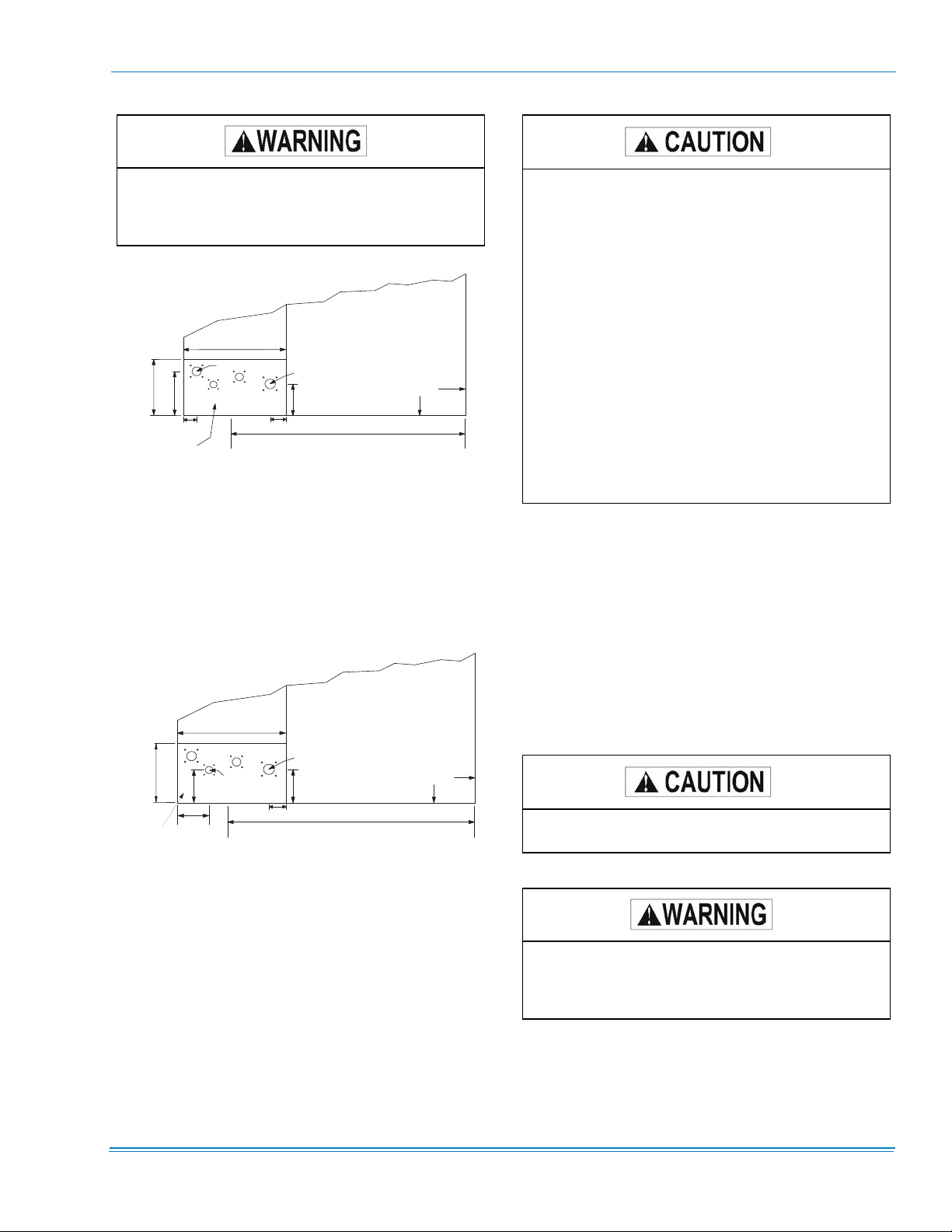
If installing a field mounted disconnect on the unit, refer to
Figure 15 for the recommended mounting location.
Unitstrut™ or equivalent rails should be mounted as shown to
provide structure for mounting. The location of the rails
should be adjusted to fit the disconnect within the dimensions
shown. Conduit run from the disconnect to the power entry
location in the baserail should be routed so that it does not
interfere with the doors of the unit access panels.
Refer to Figure 5 for typical field wiring and to the appropriate
unit wiring diagram mounted inside control doors for control
circuit and power wiring information.
POWER WIRING DETAIL
Units are factory wired for the voltage shown on the unit
nameplate. The main power block requires copper wires.
Refer to Electrical Data Tables 17 through 28 to size power
wiring, fuses and disconnect switch. All field supplied wiring,
fuses and disconnects must comply with applicable NEC
codes.
Power wiring is brought into the unit through the side of the
baserail or the bottom of the unit/control box inside the curb.
The baserail has a 2-1/2” diameter hole for field wiring and a
3-5/8” hole is provided for a through-the-curb connection. A
removable patch plate covers both the openings.
Waterproof connections MUST be used to ensure
that water cannot penetrate the roof or roof curb.
ERV
The ERV [Energy Recovery Ventilation] is a separate air handler that attaches to the exhaust end of the 25-40T Millennium packaged rooftop unit. The ERV is shipped separately
and assembled to the Millennium at the jobsite. An 'ERV' Millennium is shipped with an end configuration and electric
hookups designed to mate with the ERV. This option is available only with the Simplicity® control, and no other power
exhaust option can be supplied if an ERV is selected.
Use care to avoid damage when drilling holes for
the disconnect mounting.
NOTE: Since not all local codes allow mounting a discon-
nect on the unit, please confirm compliance with
local code before mounting a disconnect on the unit.
Electrical wiring must be sized properly to carry the load.
Each unit must be wired with a separate branch circuit fed
directly from the meter panel and properly fused.
When connecting electrical power and control wiring to the unit, waterproof connectors MUST BE
USED so that water or moisture cannot be drawn
into the unit during normal operation. The above
waterproofing conditions will also apply when
installing a field-supplied disconnect switch.
Johnson Controls Unitary Products 15
The ERV incorporates a rotating heat exchange wheel and a
pair of exhaust blowers. It exhausts return air through the
wheel, capturing the thermal energy of the exiting hot or cold
air as it passes. As the wheel rotates, the incoming airstream,
pulled through by the supply fan, regains that energy.
The Millennium ERV has a terminal block and mating connectors to simplify hooking up the two systems. The controls
of both units are factory set to interact properly . Power for the
ERV blower motors and controls is provided through the Millennium unit. The Millennium /ERV dataplate information
includes the ERV electrical load.
The Millennium Simplicity® control has parameters for the
ERV; refer to the parameter list. When economizer and ERV
options are selected on the same unit, the Simplicity® control
and the ERV have specific connections and internal rules for
that operation.
Also refer to the ERV Installation Instructions packaged with
the ERV.
882108-YIM-B-1012
GAS HEATING
On VAV units with gas fired furnace, ALL INDIVIDUAL ROOM DAMPER BOXES MUST BE CONTROLLED FULL OPEN DURING HEATING
OPERATION TO ENSURE PROPER AIRFLOW
OVER THE FURNACE. A control contact powered
by the “VAV OPEN” terminals on the Simplicity®
control is provided for the damper box interlock.
this contact is normally open, and is closed during
heating operation.
GAS PIPING
Proper sizing of gas piping depends on the cubic feet per
hour of gas flow required, specific gravity of the gas and the
length of run. National Fuel Gas Code Z223.1-Latest Edition
should be followed in all cases unless superseded by local
codes or gas company requirements. Refer to Table 14.
The heating value of the gas may differ with locality. The
value should be checked with the local gas utility.
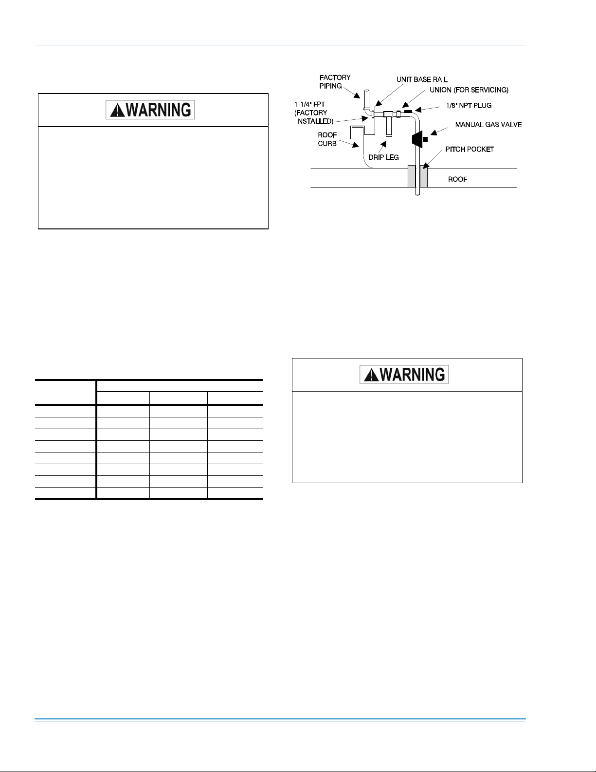
FIGURE 6 - TYPICAL GAS PIPING CONNECTION
Gas piping recommendations:
1. A drip leg and a ground joint union must be installed in
the gas piping.
2. When required by local codes, a manual shut-off valve
will have to be installed outside of the unit.
3. Use wrought iron or steel pipe for all gas lines. Pipe dope
should be applied sparingly to male threads only.
TABLE 14: PIPE SIZES
LENGTH IN
FEET
10 1,050 1,600 3,050
20 730 1,100 2,100
30 590 890 1,650
40 - 760 1,450
50 - - 1,270
60 - - 1,150
70 - - 1,050
80 - - 990
1.
Maximum capacity of pipe in cubic feet of gas
per hour (based upon a pressure drop of 0.3 inch
water column and 0.6 specific gravity gas.
NOTE: There may be a local gas utility requirement specify-
ing a minimum diameter for gas piping. All units
require a 1-1/4 inch pipe connection at the entrance
fitting. Line should not be sized smaller than the
entrance fitting size.
NOMINAL IRON PIPE, SIZE
1-1/4 IN.
1
1-1/2 IN.
1
2 IN.
1
GAS CONNECTION
The gas supply line should be routed within the space and
penetrate the roof at the gas inlet connection of the unit.
Refer to Figures 11 through 14 to locate the access opening.
Typical supply piping arrangements are shown in Figure 6.
Natural gas may contain some propane. Propane,
is an excellent solvent and will quickly dissolve
white lead or most standard commercial pipe sealing compounds. Therefore, special shellac base
pipe dope compounds such as Gaskolac or Stalastic, and compounds such as Rectorseal #5,
Clyde’s or John Crane must be applied for wrought
iron or steel pipe.
4. All piping should be cleaned of dirt and scale by hammering on the outside of the pipe and blowing out the
loose particles. Before initial start-up, be sure that all of
the gas lines external to the unit have been purged of air.
5. The gas supply should be a separate line and installed in
accordance with all safety codes as prescribed under
Limitations. After the gas connections have been completed, open the main shutoff valve admitting normal gas
pressure to the mains. Check all joints for leaks with
soap solution or other material suitable for the purpose.
NEVER USE A FLAME.
6. The furnace and its individual manual shut-off valve must
be disconnected from the gas supply piping system
during any pressure testing of that system at test pressures in excess of 0.5 psig.
16 Johnson Controls Unitary Products
Disconnect gas piping from unit when leak testing
at pressures greater than 0.5 psig. Pressures
greater than 0.5 psig will cause gas valve damage
resulting in a hazardous condition. If gas valve is
subjected to pressure greater than 0.5 psig, it must
be replaced.
882108-YIM-B-1012
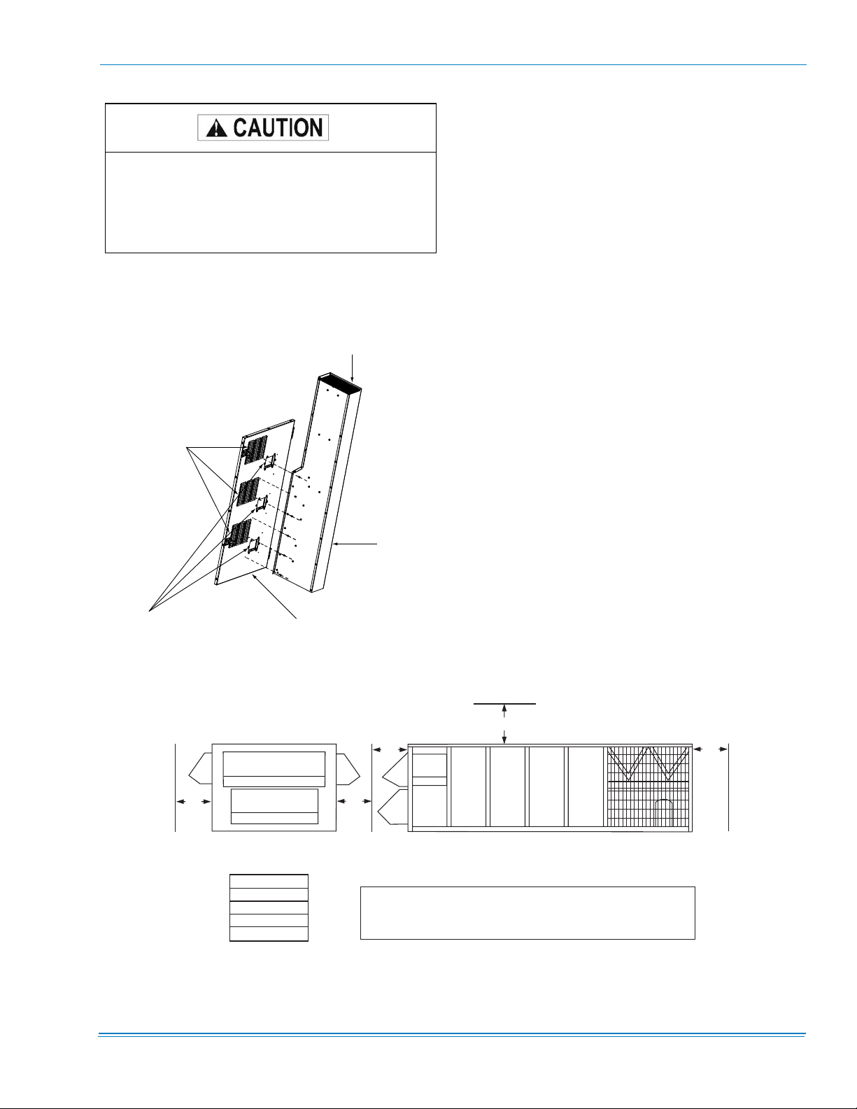
VENT AND COMBUSTION AIR
NOTE: All the hoods and hardware are shipped within the
evaporator section. Each hood must be properly
attached to the furnace doors to assure proper
operation and compliance with CSA/ETL safety certification. (Refer to Figure 7.)
The products of combustion are discharged horizontally
through hooded openings in the gas heat access doors.
7. A 1/8 inch N.P.T. plugged tapping, accessible for test
gage connection, must be installed immediately
upstream of the gas supply connection to the furnace.
EXHAUST VENT OUTLET
COMBUSTION
AIR INLET
VENT FLUE
ASSEMBLY
REMOVE SHIPPING
LABELS PRIOR TO
VENT INSTALLATION
HEAT SECTION DOOR
FIGURE 7 - VENT AND COMBUSTION AIR
HOODS
(Figure 7)
1. Remove the shipping covers that are attached to the
heat section door covering the flue outlets.
2. Locate the flue which is shipped in the evaporator section.
3. Place the flue over the flue outlet and attach with screws
provided.
4. Refer to the Gas Furnace Operation Instruction in the
Start-up Section of this manual for further instructions.
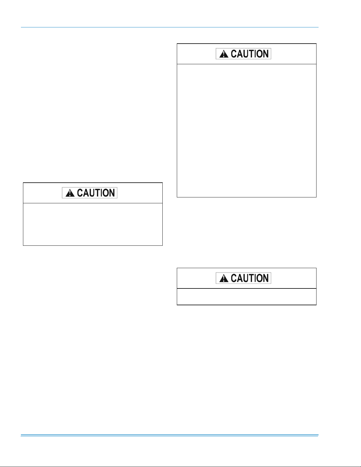
10'
RIGHT
END
60"
60"
REAR
60"
FRONT
LEFT
END
60"
* Front is the side with access to the Electrical/Gas Controls
LEFT
RIGHT
REAR
FRONT
TOP
60"
60"
60"
60"
10'
NOTE: DO NOT use the unit roof to support any type of
structure bracing.
FIGURE 8 - CLEARANCES
Johnson Controls Unitary Products 17
882108-YIM-B-1012
ELECTRIC HEAT
Units with electric heat are fully wired and operational when
shipped. Constant volume units are designed for two equal
steps of capacity for 80 and three for 108 kWH heat; 40 kW
heat is one step only . Heat outputs on VA V units are all turned
on together at full heat capacity.
HOT WATER HEAT
The YORK Millennium units (25, 30, and 40 Ton sizes) can be
furnished with a YORK hot water coil as the heat source. One
or two row coil units will be factory installed in the heating
section.
NOTE: The hot water control valve will not be provided. The
installer will need to provide a hot water control
valve, to connect the hot water piping and power
wiring at the job site for the hot water heat section to
be operational.
There are no provisions in the coil or control
sequence to prevent freezing of condensate. The
control valve, piping and field installed wiring connections are particularly vulnerable because they
are installed in the vestibule outside of the conditioned air stream. The installing party will be
responsible for properly insulating and installing
power and control wiring, to the actuator and piping.
In one row hot water coil systems DO NOT exceed
a 40 gallons per minute flow rate.
In two row hot water coil systems DO NOT exceed
an 80 gallons per minute flow rate.
Condensate will freeze on the control valve and
piping if they are not properly insulated. Insulating
the control valve and piping is the responsibility of
the installing party.
DO NOT use hot water coils as steam coils under
any circumstances.
All piping, control valves, and wiring that is field
installed must be properly insulated and conform
to all local and national codes.
NOTE: For all hot water coils the entering water tempera-
ture should not exceed 200°F.
The hot water coil is located downstream of the supply air fan
and just above the supply air opening in the bottom of the
unit.
Refer to Tables 50 through 58 and Figures 27 through 40 for
flow rate and capacity.
PIPING CONNECTIONS
The hot water piping must enter the unit through the floor of
the heat section compartment. The access doors to the compartment are gasketed so the compartment can be sealed.
However, as added protection for water leakage into the
space, the piping access holes should be sealed with a heat
resistant mastic Figure 9 shows the location of the compartment and piping connections.
Piping access holes should be sealed with a heat
resistant mastic to prevent damage to equipment.
18 Johnson Controls Unitary Products
882108-YIM-B-1012
DO NOT use tin based solder. Brazing with tin
based solder could cause equipment damage or
possible injury to tenants of the structure that is
being conditioned.
( 1 O R 2 R O W )
C O N D E N S I N G
S E C T I O N
8 8 . 7 5 "
O U T S I D E O F
B A S E R A I L
1 5 . 8 "
1 1 . 8 8 "
H E A T S E C T I O N
C O M P A R T M E N T
2 . 2 5 "
H O T W A T E R
C O I L
2 6 "
I N L E T ( 2 " )
C
L
O U T L E T ( 2 " )
8 . 3 8 "
2 . 5 5 "
FIGURE 9 - HOT WATER PIPING CROSS-SEC-
TION
STEAM HEAT
The YORK Millennium units (25, 30 and 40 Ton sizes) can be
furnished with a YORK single row steam coil. YORK steam
coils are a factory installed option.
T O P V I E W
C O N D E N S I N G
S E C T I O N
O U T S I D E O F
B A S E R A I L
1 5 . 8 "
S T E A M
C O I L
2 6 "
O U T L E T ( 1 1 / 2 " )
I N L E T ( 2 " )
8 "
8 . 3 8 "
All piping and control valves, and wiring that is
field installed must be properly insulated and conform to all local and national codes.
There are no provisions in the coil or control
sequence to prevent freezing of condensate. The
control valve, piping and field installed wiring connections are particularly vulnerable because they
are installed in the vestibule outside of the conditioned air stream. The installing party will be
responsible for properly insulating and installing
power and control wiring, to the actuator and piping.
DO NOT use steam coils as hot water coils under
any circumstances.
In steam coil systems, the steam pressure shall
not exceed 15 PSI.
PIPING CONNECTIONS
Refer to Tables 46 through 49 and Figures 41 and 42 for flow
rate and capacity.
The steam piping must enter the unit through the floor of the
heat section compartment. The access doors to the compartment are gasketed so the compartment can be sealed. However, as added protection for condensate leakage into the
space, the piping access holes should be sealed with a heat
resistant mastic. The following figure illustrates the location of
the compartment and piping connections.
2 . 5 5 "
C
L
8 8 . 7 5 "
Piping access holes should be sealed with a heat
resistant mastic to prevent damage to equipment.
H E A T S E C T I O N
C O M P A R T M E N T
9 "
FIGURE 10 - STEAM PIPING CROSS-SECTION
NOTE: The steam control valve, power and control wiring to
the actuator of the valve is the responsibility of the
installing party.
Johnson Controls Unitary Products 19
DO NOT use tin based solder. Brazing with tin
based solder could cause equipment damage or
possible injury to tenants of the structure that is
being conditioned.
882108-YIM-B-1012
STATIC PRESSURE CONTROL PLASTIC TUBING
On units with variable frequency drives (VFD’s) or inlet guide
vanes (IGV's) on the supply blower and/or power exhaust
fans, pressure sensing tubing must be field supplied and
installed. All tubing must be installed from the transducers
(located in the unit) to the location in the building (or
ductwork) where a constant pressure is desired. The tubing
must also be installed from the transducers to a low-side reference to the atmosphere.
The supply air duct pressure sensor (DPS) is located in the
control box directly below the Millennium Simplicity® control.
Plastic tubing (1/4”) must be run from the high pressure tap of
the transducer to a static pressure tap (field supplied) in the
supply duct located at a point where constant pressure is
desired. Tubing must also be run between the low pressure
tap of the transducer to atmospheric pressure. Changing the
adjustment is done to the duct pressure setpoint in the control.
EXHAUST STATIC PRESSURE
If a modulating-damper or variable frequency drive power
exhaust is installed, there will be a building pressure sensor
(BPS) in the control box directly below the Millennium Sim-
plicity® control. This ± .25 0-5VDC transducer sends a building pressure signal to the control. A sensing tube must be
installed from a representative location in the building to the
HI port of the transducer. Tubing must also be run between
the low pressure tap of the transducer to atmospheric pressure.
Changing the adjustment is done to the building pressure setpoint in the control.
Do not run plastic tubes in the supply or return air
ducts as air movement could cause erroneous
sensing. If tubes penetrate bottom of unit be sure
openings are sealed against air and water leakage.
20 Johnson Controls Unitary Products
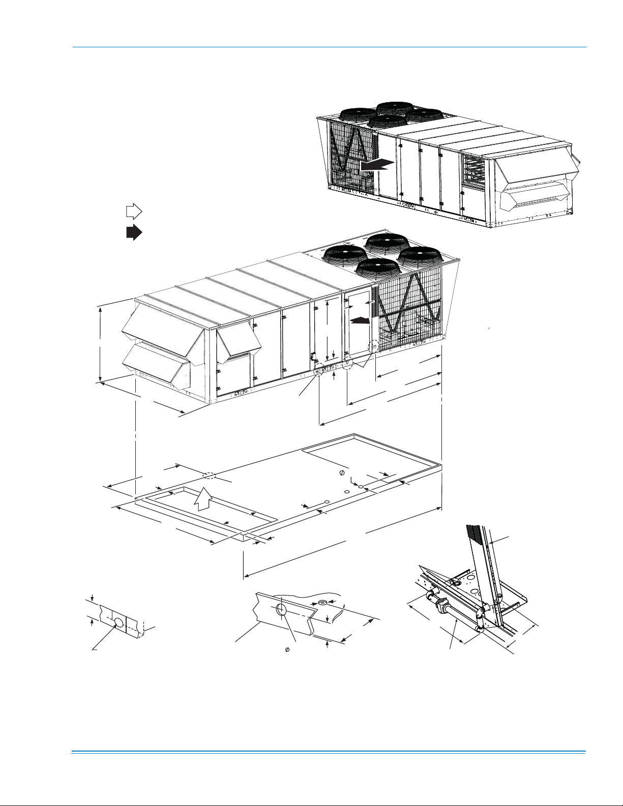
64"
RETURN AIR
SUPPLY AIR
92"
REAR
DETAIL
FRONT
SEE
B
SEE
DETAIL
C
882108-YIM-B-1012
RIGHT
END
72.25”
99.5”
131.5”
LEFT
END
4-5/8”
1-1/2" FPT
DETAIL A
(DRAIN CONNECTION)
LEFT
END
80.93"
4.5"
BASE RAIL
83"
REAR
4.5"
SEE
71.61"
26"
DETAIL
A
38.59"
6.46"
127.5"
FRONT
C
4.5"
BASE RAIL
DETAIL B
(ELECTRICAL CONNECTION)
FOR COOLING ONLY AND ALL HEATING APPLICATIONS
L
2.31”
Ø 2-1/2”
OPEN
3.625"
240"
3-5/8"
6.45"
15.89"
RIGHT
END
2-1/2”
DIA. HOLES
12"
MIN
C
L
28”
1-1/4” NPT
(GAS CONNECTION
THROUGH CURB)
88.7 "
7”
DETAIL C
TO GAS VALVE
MANIFOLD
11”
FIGURE 11 - BOTTOM SUPPLY AND RETURN
Johnson Controls Unitary Products 21
882108-YIM-B-1012
LEFT END
RETURN AIR
SUPPLY AIR
7-7/8”
64"
LEFT END
76-3/8”
92"
8
0.93"
REAR
REAR
24.9”
SEE
DETAIL
A
"
6.25”
FRONT
4.5"
71.61"
SEE
DETAIL
B
6.46"
SEE
DETAIL
C
3.625"
26"
FRONT
240"
NOTE:
FACTORY INSTALLED POWER
EXHAUST CANNOT BE ORDERED
WITH END RETURN.
RIGHT END
72.25”
99.5”
131.5”
RIGHT
END
OPEN
12"
MIN
15.89"
C
L
88.7"
4-5/8”
BASE RAIL
1-1/2" FPT
BASE RAIL
DETAIL A
(DRAIN CONNECTION)
(ELECTRICAL CONNECTION)
FOR COOLING ONLY AND ALL HEATING APPLICATIONS
FIGURE 12 - END RETURN, BOTTOM SUPPLY
2-1/2"
DETAIL B
2.31”
3-5/8"
6.45"
2-1/2”
DIA. HOLES
28”
1-1/4” NPT
7”
DETAIL C
(GAS CONNECTION
THROUGH CURB)
TO GAS VALVE
MANIFOLD
11”
22 Johnson Controls Unitary Products
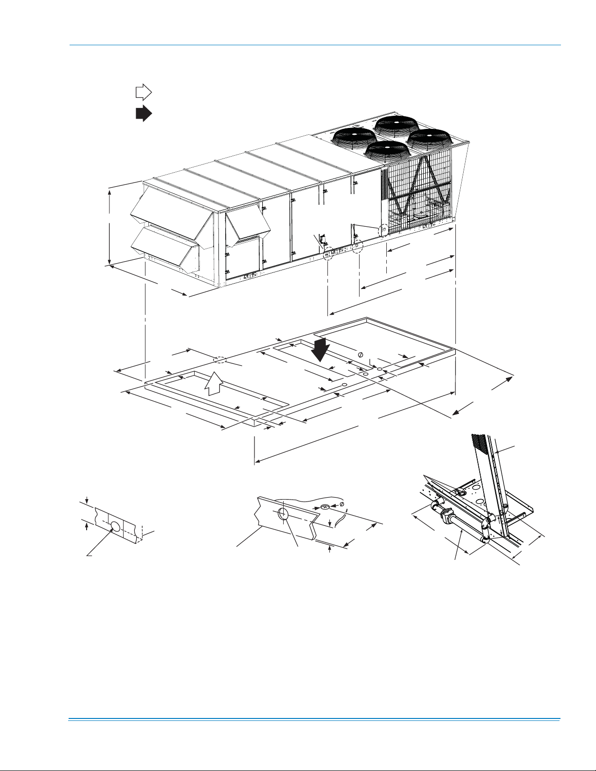
FRONT SUPPLY: FOR COOLING ONLY APPLICATIONS
REAR SUPPLY: FOR COOLING ONLY OR GAS HEAT APPLICATIONS
882108-YIM-B-1012
FRONT
64"
RETURN AIR
SUPPLY AIR
REAR
92"
LEFT END
80.93"
4.5"
REAR
RIGHT END
26"
55"
72.25”
99.5”
FRONT
SEE
DETAIL
B
8.15"
SEE
DETAIL
C
131.5”
RIGHT
END
REAR
OPEN
SEE
DETAIL
A
6.46"
3.625"
12"
MIN
38.59"
FRONT
4.5"
2.31”
BASE RAIL
2-1/2"
DETAIL B
(ELECTRICAL CONNECTION)
FOR COOLING ONLY AND ALL HEATING APPLICATIONS
240"
2-1/2”
DIA. HOLES
3-5/8"
6.45"
28”
1-1/4” NPT
DETAIL C
(GAS CONNECTION
THROUGH CURB)
TO GAS VALVE
MANIFOLD
7”
11”
LEFT END
4-5/8”
BASE RAIL
1-1/2" FPT
DETAIL A
(DRAIN CONNECTION)
83"
FIGURE 13 - BOTTOM RETURN, FRONT & REAR SUPPLY
Johnson Controls Unitary Products 23
882108-YIM-B-1012
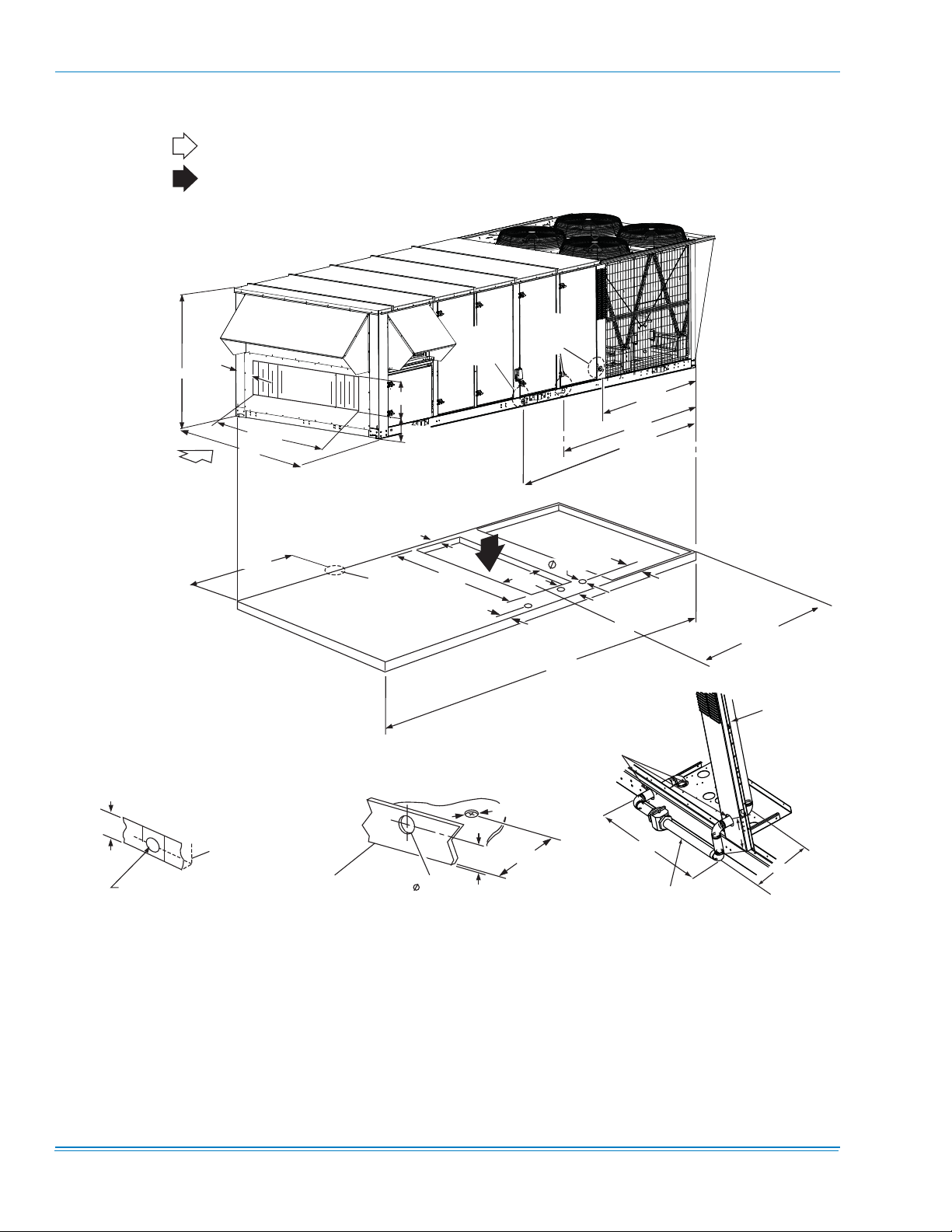
FRONT SUPPLY: FOR COOLING ONLY APPLICATIONS
REAR SUPPLY: FOR COOLING ONLY OR GAS HEAT APPLICATIONS
RETURN AIR
SUPPLY AIR
REAR
REAR
26
26"
FRONT
"
55"
64”
7-7/8”
76-3/8”
92”
LEFT
END
8 0 . 9 3 "
LEFT
END
24.9”
6.25”
REAR
SEE
DETAIL
A
SEE
DETAIL
B
FRONT
6 . 4 6 "
26"
55"
8.15"
DETAIL
3 . 6 2 5 "
FRONT
2 4 0 "
SEE
C
131.5”
OPEN
72.25”
99.5”
RIGHT
END
1 2 "
M I N
2-1/2”
DIA. HOLES
RIGHT
END
TO GAS VALVE
MANIFOLD
3-5/8"
4-5/8”
BASE RAIL
1-1/2" FPT
DETAIL A
(DRAIN CONNECTION)
6.45"
BASE RAIL
2.31”
2-1/2"
DETAIL B
(ELECTRICAL CONNECTION)
FOR COOLING ONLY AND ALL HEATING APPLICATIONS
28”
1-1/4” NPT
(GAS CONNECTION
THROUGH CURB)
7”
11”
DETAIL C
FIGURE 14 - END RETURN, FRONT & REAR SUPPLY
24 Johnson Controls Unitary Products
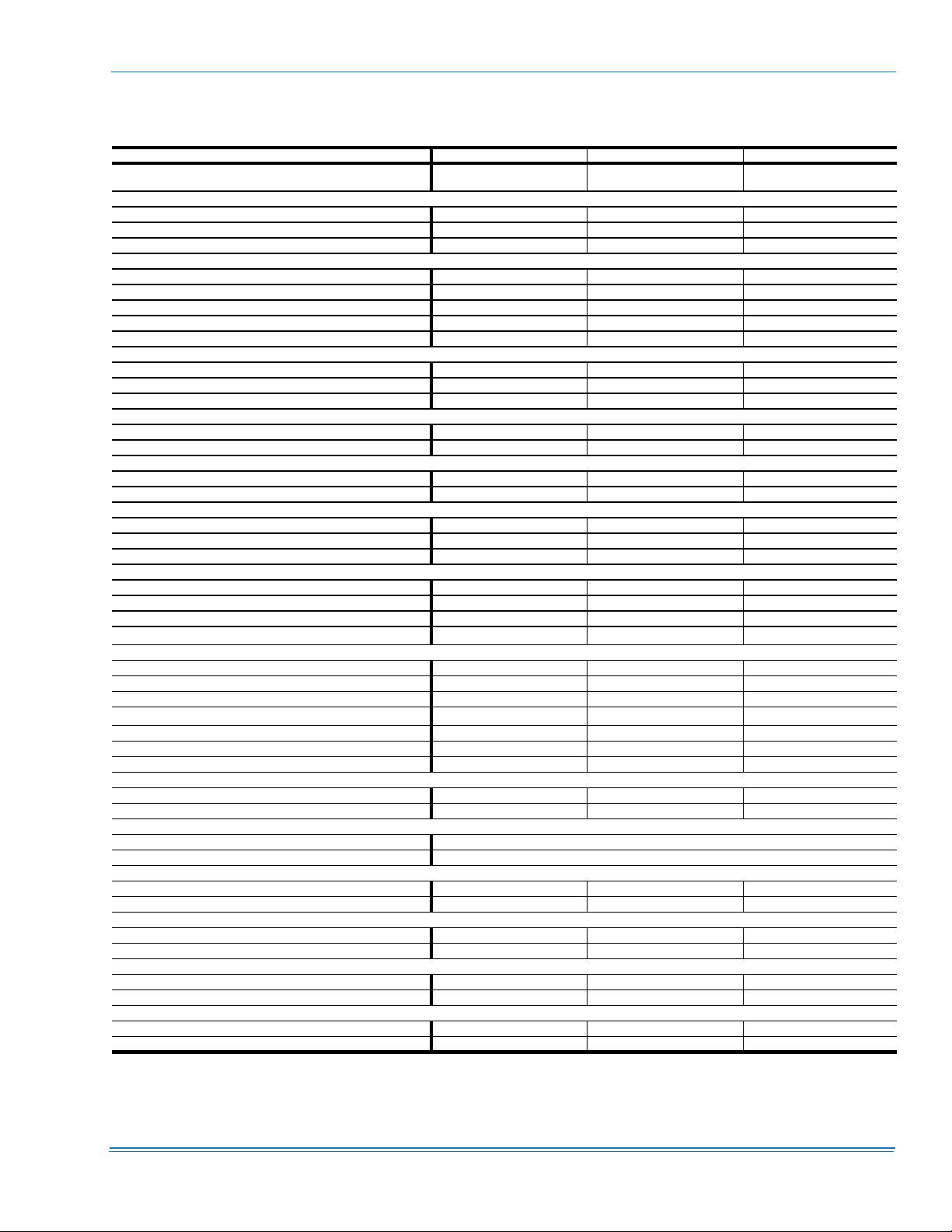
TABLE 15: GENERAL PHYSICAL DATA
UNIT SIZE 25 TON 30 TON 40 TON
NIT EER / IPLV
U
(S
TANDARD CAPACITY EVAPORATOR)
10.5 / 12.3
C
OMPRESSOR DATA
NUMBER/SIZE 4 x 5.7Ton 4 x 7 Ton 4 x 8.6 Ton
YPE Scroll Scroll Scroll
T
NIT CAPACITY STEPS 25%, 50%, 75%, 100% 25%, 50%, 75%, 100% 25%, 50%, 75%, 100%
U
NDOOR FAN AND DRIVE
I
NUMBER / TYPE 1 / FC 1 / FC 1 / FC
IAMETER X WIDTH (INCHES) 22 x20 22 x 20 25 x 22
D
CFM R
ANGE 7.5 - 20 10 - 25 10 - 25
HP R
ANGE (FULL LOAD) 6,000 - 12,500 6,000 - 15,000 8,000 - 18,000
ANGE 0.2” - 4.0” 0.2" - 4.0” 0.2" - 4.0"
ESP R
XHAUST FAN
E
NUMBER/SIZE/TYPE 1/FC 2/FC 2/FC
ANGE (SINGLE MOTOR) 5 - 10 7.5 - 15 7.5 - 15
HP R
CFM 3,000 - 9,000 4,000 - 15,000 4,000 - 18,000
VAPORATOR COIL
E
SIZE (SQ. FT.) 26.0 26.0 30.4
OWS/FPI 3 / 16 4 / 16 4 / 16
R
ONDENSER COIL
C
SIZE (SQ. FT.) 65 78 104
OWS/FPI 2/16 2 /16 2 /16
R
ONDENSER FANS
C
QUANTITY / DIAMETER (INCHES) 4 / 24 4 / 24 4 / 30
OMINAL CFM 6,800 7,200 9,600
N
OTOR HP 1.0 1.5 1.5
M
K
W RANGE 40 - 108 40 - 108 40 - 108
KW / CAPACITY STEPS (CV/VAV) 111
40
KW / CAPACITY STEPS (CV/VAV) 2 / 1 2 / 1 2 / 1
80
108
KW / CAPACITY STEPS (CV/VAV)
LECTRIC HEAT
E
3 / 1
2
NATURAL GAS HEAT
UNIT SIZE 25 TON 30 TON 40 TON
267 MBH C
533 MBH C
800 MBH C
APACITY STEPS (CV/VAV) 1 / 1 1 / 1 1 / 1
APACITY STEPS (CV/VAV) 2 / 1 2 / 1 2 / 1
APACITY STEPS (CV/VAV) --
267 MBH “MODULATING” CAPACITY STEPS (CV ONLY) 6 / 1 6 / 1 6 / 1
533 MBH “M
800 MBH “M
ODULATING” CAPACITY STEPS (CV ONLY) 12 / 2 12 / 2 12 / 2
ODULATING” CAPACITY STEPS (CV ONLY) - - 17 / 3
OT WATER COIL
H
SIZE (INCHES) 22.5” x 65” 22.5" X 65” 22.5" X 65”
APACITY 25 T on 30 Ton 40 Ton
C
TEAM COIL
S
SIZE (INCHES) 21" X 65"
YPE Steam Coil
T
UMBER / SIZE 4 / 16 x 25 & 6 / 20 x 25 4 / 16 x 25 & 6 / 20 x 25 4 / 16 x 25 & 6 / 20 x 25
N
ACE AREA (SQ. FT.) 30.4 30.4 30.4
F
UMBER / SIZE 4 / 16 x 25 & 6 / 20 x 25 4 / 16 x 25 & 6 / 20 x 25 4 / 16 x 25 & 6 / 20 x 25
N
ACE AREA (SQ. FT.) 30.4 30.4 30.4
F
ILTERS 65% RIGID W/ 2” TA PREFILTERS
F
ILTERS 2" TA
F
ILTERS 2" PLEATED, 30%
F
NUMBER / SIZE 4 / 16 x 25 & 6 / 20 x 25 4 /16 x 25 & 6 / 20 x 25 4 / 16 x 25 & 6 / 20 x 25
ACE AREA (SQ. FT.) 30.4 30.4 30.4
F
ILTERS 95% RIGID W/ 2” TA PREFILTERS
F
NUMBER / SIZE 4 ea. 16 x 25 / 6 ea. 20 x 25 4 ea. 16 x 25 / 6 ea. 20 x 25 4 ea. 16 x 25 / 6 ea. 20 x 25
ACE AREA (SQ. FT.) 30.4 30.4 30.4
F
1.
Cooling Only Unit Efficiency/ Gas Electric Unit Efficiency is 10.0
2.
Unit Control Board with 3 heating outputs only, all other Unit Control Boards 2 / 1.
10.1
1
3 / 1
/ 11.0
2
882108-YIM-B-1012
10.5 / 11.2
2
3 / 1
2
3 / 1
Johnson Controls Unitary Products 25
882108-YIM-B-1012
TABLE 16: REFRIGERANT FACTORY CHARGE R-410A
UNIT (TONS) MODEL
SYSTEM #1 SYSTEM #2 SYSTEM #3 SYSTEM #4
25 wo/HGBP 13lb 8oz 12lb 8oz 12lb 8oz 12lb 8oz
25 w/HGBP 14lb 12lb 8oz 12lb 8oz 12lb 8oz
30 wo/HGBP 16lb 16lb 8oz 14lb 18lb 4oz
30 w/HGBP 16lb 8oz 17lb 14lb 8oz 18lb 12oz
40 wo/HGBP 17lb 10oz 17lb 10oz 19lb 13oz 19lb 13oz
40 w/HGBP 18lb 2oz 18lb 2oz 20lb 5oz 20lb 5oz
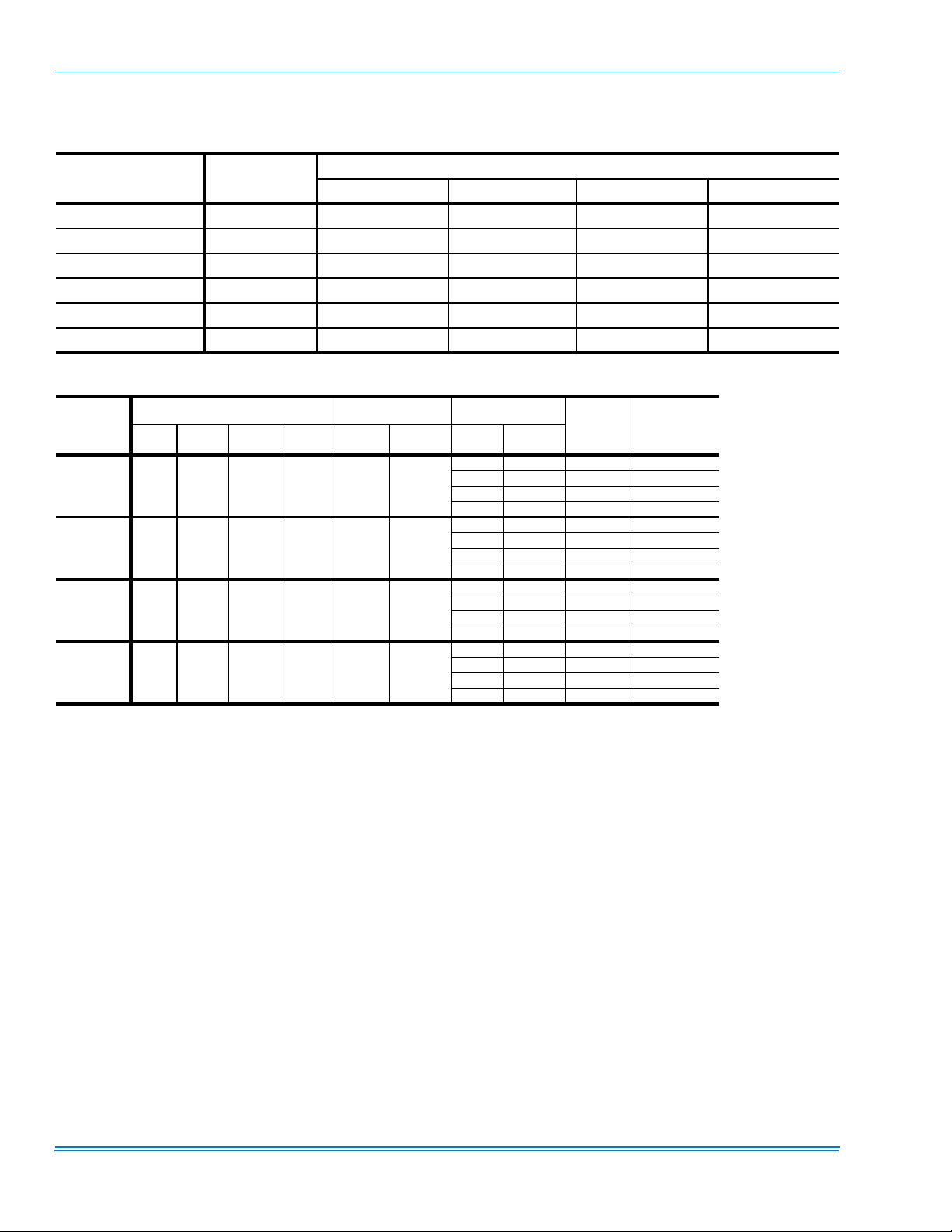
TABLE 17: ELECTRICAL DATA 25 TON BASIC UNIT R-410A
Voltage
208-3-60 4 22.4 149 35 4 4.5
230-3-60 4 22.4 149 35 4 4.3
460-3-60 4 10.6 75 16.5 4 2.15
575-3-60 4 7.7 54 12 4 1.7
1.
Minimum Circuit Ampacity.
2.
Dual Element, Time Delay Type.
3.
HACR type per NEC.
Compressors (each) OD Fan Motors
Qty RLA LRA MCC Qty FLA HP FLA
Supply Blower
7.5 24.2 138 150
10 30.8 146 175
15 46.2 165 200
20 59.4 182 225
7.5 22 134 150
10 28 142 150
15 42 159 200
20 54 174 225
7.5 11 65 70
10 14 69 80
15 21 77 90
20 27 85 110
7.5 9 49 50
10 11 51 60
15 17 59 70
20 22 65 80
Motor
CHARGE
MCA
(Amps)
1
Max Fuse2/
Breaker
Size
(Amps)
3
26 Johnson Controls Unitary Products
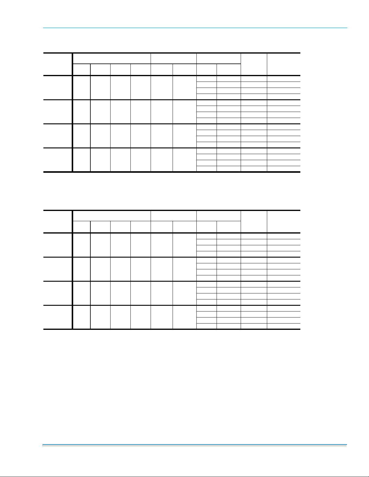
TABLE 18: ELECTRICAL DATA 30 TON BASIC UNIT R-410A
Voltage
Compressors (each) OD Fan Motors
Qty RLA LRA MCC Qty FLA HP FLA
208-3-60 4 25.0 164 39 4 5.8
230-3-60 4 25.0 164 39 4 5.8
460-3-60 4 12.0 100 19 4 2.9
575-3-60 4 9.0 78 14 4 2.2
1.
Minimum Circuit Ampacity.
2.
Dual Element, Time Delay Type.
3.
HACR type per NEC.
Supply Blower
10 30.8 162 175
15 46.2 181 225
25 74.8 217 250
20 59.4 197 250
10 28 158 175
15 42 176 200
25 68 208 250
20 54 191 225
10 14 77 90
15 21 86 100
20 27 93 110
25 34 102 125
10 11 59 60
15 17 66 80
20 22 72 90
25 27 79 100
Motor
MCA
(Amps)
1
Max Fuse2/
Breaker
Size
(Amps)
882108-YIM-B-1012
3
TABLE 19: ELECTRICAL DATA 40 TON BASIC UNIT R-410A
Voltage
Compressors (each) OD Fan Motors
Qty RLA LRA MCC Qty FLA HP FLA
208-3-60 4 30.1 255 47 4 5.8
230-3-60 4 30.1 255 47 4 5.8
460-3-60 4 16.7 114 26 4 2.9
575-3-60 4 12.2 80 19 4 2.2
1.
Minimum Circuit Ampacity.
2.
Dual Element, Time Delay Type.
3.
HACR type per NEC.
Supply Blower
10 30.8 182 200
15 46.2 201 225
20 59.4 218 250
25 74.8 237 300
10 28 179 200
15 42 196 225
20 54 211 250
25 68 229 250
10 14 97 110
15 21 105 125
20 27 112 125
25 34 121 150
10 11 72 80
15 17 79 90
20 22 85 100
25 27 91 110
Motor
MCA
(Amps)
1
Max Fuse2/
Breaker
Size
(Amps)
3
Johnson Controls Unitary Products 27
882108-YIM-B-1012
TABLE 20: ELECTRICAL DATA 25 TON W/ELECTRIC HEAT R-410A
Compressors
Voltage
(each)
Qty RLA LRA MCC FLA HP FLA Option KW Applied Stages Amps
208-3-60 4 22.4 149 35 4.5
230-3-60 4 22.4 149 35 4.3
460-3-60 4 10.6 75 16.5 2.15
575-3-60 4 7.7 54 12 1.7
1.
Minimum Circuit Ampacity.
2.
Dual Element, Time Delay Type.
3.
HACR type per NEC.
OD Fan
Motors
(each)
Supply Blower
Motor
Electric Heat Option
7.5 24.2
10 30.8 146 175
15 46.2 165 200
E4 40 30 1 83
20 59.4 182 225
7.5 24.2
10 30.8 205 225
15 46.2 225 250
E8 80 60 2 167
20 59.4 241 300
7.5 22
10 28 150 150
15 42 168 200
E4 40 36.8 1 92
20 54 183 225
7.5 22
10 28 220 250
15 42 237 250
E8 80 73.6 2 184
20 54 252 300
7.5 11
10 14 75 80
15 21 84 90
E4 40 36.8 1 46
20 27 91 110
7.5 11
10 14 110 125
15 21 119 125
E8 80 73.6 2 92
20 27 126 150
7.5 11
10 14 142 175
15 21 151 175
E1 108 99.4 3 125
20 27 158 175
7.5 9
10 11 64 70
15 17 72 80
E4 40 36.8 1 40
20 22 78 80
7.5 9
10 11 94 110
15 17 102 110
E8 80 73.6 2 80
20 22 108 125
7.5 9
10 11 122 150
15 17 130 150
E1 108 99.4 3 108
20 22 136 150
Max Fuse2/
1
MCA
(Amps)
138 150
197 225
143 150
212 250
71 80
106 125
138 150
62 70
92 110
120 150
Breaker
Size
(Amps)
3
28 Johnson Controls Unitary Products
 Loading...