

Page 1
INSTALLATION
MILLENNIUM™ ROOFTOP
INSTRUCTION
CONTENTS
DESCRIPTION . . . . . . . . . . . . . . . . . . . . . . . . . . . . . 2
CV UNITS W/O ECONOMIZER . . . . . . . . . . . . . . . . 3
UNITS W/O ECONO & OPT GAS OR ELEC HEAT . . . . 5
CV UNITS WITH ECONOMIZER . . . . . . . . . . . . . . 10
CV UNITS W/ ECONOMIZER & OPTIONAL HEAT . . . 11
LIST OF FIGURES
1 POWER & CONTROL WIRING LOCATION . . . . . . . . . 3
2 EXISTING CTRL PANEL COMPONET LOC . . . . . . . . . 3
3 TYPICAL THERMOSTAT WIRING . . . . . . . . . . . . . . . . 3
4 NEW LOW VOLTAGE CONTROL COMPONETS . . . . . 4
5 CV UNIT W/O A ECONO WIRING DIA . . . . . . . . . . . . . 6
6 CV UNIT W/O ECONO WIRING DIA . . . . . . . . . . . . . . . 7
7 COOLING UNIT W/ ELEC HT DIA & W/O ECONO . . . . 8
8 CV UNIT W/ GAS HT & W/O ECONO WIRING DIA . . . 9
9 CV UNIT W/ ECONO WIRING DIA . . . . . . . . . . . . . . . 12
10CV UNIT W/ ECONO CONNECTION DIA . . . . . . . . . . 13
11CV UNIT W/ GAS HT & ECONO WIRING DIA . . . . . . 14
12UNIT W/ ECONO & ELEC HT WIRING DIA . . . . . . . . . 15
CONTROLS UPGRADE FROM STYLE A TO
STYLE C
MODELS:
Y13
Y14
STYLE A TO STYLE C
LIST OF TABLES
1 PARTS SUPPLIED FOR CONTROL CHANGE . . . . . . . 2
2 PARTS SUPPLIED FOR CV UNITS W/O ECONO . . . . 2
3 PARTS SUPPLIED FOR CV UNITS W/ OPT HEAT . . . 3
4 PARTS SUPPLIED FOR CV UNITS W/ ECONO . . . . . 10
5 PARTS SUPPLIED FOR CV UNITS W/ OPT HEAT . . 10
CAUTION: READ ALL SAFETY GUIDES BEFORE YOU
BEGIN TO INSTALL YOUR UNIT.
SAVE THIS MANUAL
035-16728-000 REV A (799)Form 530.70-N1.11Y
Page 2
530.70-N1.11Y
DESCRIPTION
The installation of this kit (2RT04701A) replaces the W7400
module and will obsolete the T7400 thermostat. A new thermostat will be required to operate the unit.
This kit contains all necessary electrical components, sheetmetal parts, and wires to replace the W7400 module and the
T7400 thermostats used in all Constant Volume 30-40 Ton
Millennium Style A units. The kit contains the wiring needed
for all options including CV W/ Economizer, CV W/O Economizer, Optional Gas Heat, and Optional Electric Heat. Figures 1 and 2 illustrate the location of the Millennium controls
and the location of the W7400 in the control section. The
new low-voltage electric box will be as shown in Figure 4.
TABLE 1: PARTS SUPPLIED FOR CONTROL
CHANGE
QTY PART NO. DESCRIPTION
1 073-21599-000 Backplate Bracket
1 025-16100-000 Terminal Block, 10 Pole
1 025-32699-000 Transformer, 24V to 24V
5 024-24116-000 Isolation Relay
4 021-15512-000 #10 Sheet metal Screws
1 035-16634-000
1 035-16636-000
CV w/ECON
Wiring Diagram
CV w/ECON
Connection Diagram
TABLE 2: PARTS SUPPLIED FOR CV UNITS W/O
ECONOMIZER
QTY PART NO. DESCRIPTION
1 373-18641-653
1 373-18641-654
1 373-18641-659
1 AB008RED7171230 230/R
1 AB024YEL5471240 240/Y
1 AB024ORN7171244 244/O
1 AB027GRA7171248 248/GY
1 AB022GRA7171800 800/GY
1
201/R
816/R
252/R
257/Y
817/Y
818/Y
819/Y
842/BR
814/BR
813/BR
812/BR
834/BR
835/BR
1 035-16635-000 CV W/O ECON Wiring Diagram
1 035-16637-000
1 035-16165-000
1 035-16148-000 CV Gas Heat Wiring Diagram
1 373-22695-000
1 373-22694-000
1 373-22696-000
1.
See Table 4 for complete listing of wires in the CV with
Economizer Package.
2.
See T abl e 2 for complete listing of wires in the CV without Economizer Package
3.
See Tables 3 and 5 for complete listing of wires in the
CV unit with heat package
CV W/O ECON Connection
CV With Economizer Wire
CV W/O Economizer Wire
Diagram
CV Electric Heat Wiring
Diagram
1
Pkg.
2
Pkg.
CV With Heat Wire
3
1 AB007YEL7171801 801/Y
1 AB007ORN7171802 802/O
1 AB009PRP7171803 803/PR
1 AB012GRA7171821 821/GY
1 AB018BRN7171836 836/BR
1 AB027PRP7171839 839/PR
1.
See Table 3 for units with optional heat.
2 Unitary Products Group
Page 3
530.70-N1.11Y
TABLE 3: PARTS SUPPLIED FOR CV UNITS WITH
OPTIONAL HEAT
QTY PART NO. DESCRIPTION
1 373-18689-610
1 373-18689-611
1 AB144GRA7171844 844/GY
1 AB144WHT7171845 845/W
2 024-24116-000 Isolation Relay
820/Y
823/Y
822/BR
826/BR
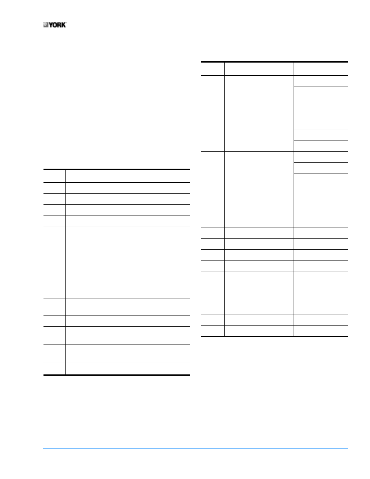
FIGURE 1: POWER & CONTROL WIRING
LOCATION
FIGURE 3 : TYPICAL THERMOSTAT WIRING
OPEN ALL DISCONNECTS BEFORE SERVICING THIS UNIT.
The new thermostat requires a thermostat cable with a minimum of 10 conductors that run from the sub-base to the control box. The new wire will be connected as shown in Figure
3.
1. Locate the W7400 control module in the box-electric
(Figures 1 and 2).
FIGURE 2 : EXISTING CONTROL PANEL COMPO-
NET LOCATION
2. Remove the following wires form the W7400 control
module and from the unit.
•201/R
•208/BR
•254/GY
•252/Y
•257/Y
•248/GY
•240/Y
•244/0
•246/PR
NOTE:
Wire ties will need to be removed to remove above
wires.
3. Disconnect wire 204/BR from the TR terminals on the
w7400 control module.
NOTE:
These wires will be used with the new controls.
4. Disconnect thermostat wire from terminals 1-4 on the
W7400 control module.
NOTE:
This wire will be used with the new controls.
NOTE: STEPS 5 THROUGH 7 ARE FOR OPTIONAL HEAT
ONLY.
Unitary Products Group 3
Page 4
530.70-N1.11Y
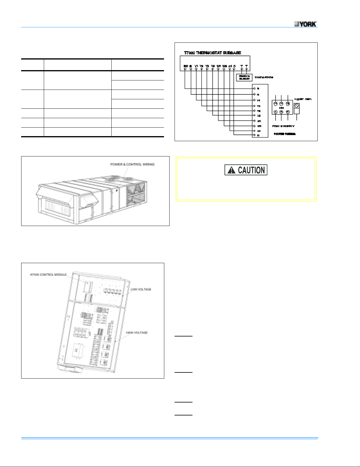
FIGURE 4 : NEW LOW VOLTAGE CONTROL COMPONETS
5. Disconnect wire 526/R from the 30FU location.
NOTE:
6. Disconnect wire 533 /GY from the W7400 c ontrol modul e
7. Disconnect wires 510/GY and 512/w from W1 & W2.
NOTE: These wires will be used with the new controls.
8. Remove the W7400 control module from the control box.
9. Locate the new control plate in box-electric in the loca-
10. Using the four drill screws secure the back plate to the
11. Locate the packet of wires marked with “No Econo-
12. Attach thermostat wires to new location TB12
NOTE:
respectively.
13. Attach wire 230/R from 8T-7 to TB12-R .
This wire will be used with the new controls.
G terminal.
tion shown in Figure 4.
box-electric.
mizer”.
(See Figure 3).
For the following steps (13-34) see Figures 5, and 6
14. Attach wire 836/BR from TB2 to 8T-6.
15. Attach wire 842/BR from 8T-6 to MR-B.
16. Attach wire 814/BR from MR-B to CR1-B.
17. Attach wire 813/BR from CR1-B to CR2-B.
18. Attach wire 812/BR from CR2-B to CR3-B.
19. Attach wire 834/BR from CR3-B to CR4-B.
20. Attach wire 835/BR from CR4-B to TB12-C.
21. Attach wire 800/GY from MR-A to TB12-G.
22. Attach wire 801/Y from CR1-A to TB12-Y1.
23. Attach wire 802/O from CR2-A to TB12-Y2.
24. Attach wire 803/PR from CR3-A to TB12-Y3.
25. Attach wire 821/GY from CR4-A to TB12-Y4.
26. Attach wire 240/Y from CR1-5 to LOR1-1-7.
27. Attach wire 244/O from CR2-5 to LOR1-2-9.
28. Attach wire 839/PR from CR3-5 to LOR2-1-7.
29. Attach wire 248/GY from CR4-5 to LOR2-2-9.
30. Attach wire 252/R from CL01 to MR-7.
4 Unitary Products Group
Page 5

530.70-N1.11Y
31. Attach wire 816/R from MR-7 to 8T-2.
32. Attach wire 201/R from 8T-1 to 30FU.
33. Attach wire 204/BR to the new location on 8T-2.
34. Attach wire 257/Y from APS-N0 to CR1-7.
35. Attach wire 817/Y from CR1-7 to CR2-7.
36. Attach wire 818/Y from CR2-7 to CR3-7.
37. Attach wire 819/Y from CR3-7 to CR4-7.
NOTE:
IF UNIT HAS OPTIONAL HEA T PLEAS E CONTINUE
WITH STEP 38.
UNITS W/O ECONOMIZER AND OPTIONAL GAS OR
ELECTRIC HEAT
Units with optional Gas or Electric heat should follow the
steps below. See Figure 7 for Gas Heat and Figure 8 for
Electric Heat.
NOTE:
38. Mount WR1 & WR2 relays in the heat section.
39. Attach wire 526/R to the new location on 8T-7.
40. Attach wire 845/W from TB12-W1 to WR1-A.
41. Attach wire 844/GY from TB12-W2 to WR2-A
42. Attach wire 820/Y from CR4-7 to WR1-7.
43. Attach wire 823/Y from WR1-7 to WR2-7
44. Attach wire 826/BR from WR1-B to WR2-B1.
45. Attach wire 822/BR from WR1-B to TB2.
46. Attach wire 512/W to the new location at WR1-5.
47. Attach wire 510/GY to the new location at WR2-5
This wire will be used with the new controls.
1
.
1
.
1
.
48. Attach wire 533/GY to the new location on TB12-G.
END OF INSTALLATION FOR CV UNIT WITHOUT ECONO-
MIZER.
1. Only on units with 480 and 780 MBH gas unit or with
80kW and 180kW electric heat.
Unitary Products Group 5
Page 6

530.70-N1.11Y
FIGURE 5 : CONSTANT VOLUME UNIT WITHOUT A ECONOMIZER WIRING DIAGRAM
6 Unitary Products Group
Page 7

530.70-N1.11Y
FIGURE 6 : CONSTANT VOLUME UNIT W/O ECONOMIZER WIRING DIAGRAM
Unitary Products Group 7
Page 8

530.70-N1.11Y
FIGURE 7 : COOLING UNIT WITH ELECTRIC HEAT DIAGRAM AND WITHOUT ECONOMIZER
8 Unitary Products Group
Page 9

530.70-N1.11Y
FIGURE 8 : CV UNIT WITH GAS HEAT AND WITHOUT ECONOMIZER WIRING DIAGRAM
Unitary Products Group 9
Page 10

530.70-N1.11Y
CV UNITS WITH ECONOMIZER
TABLE 4: P ARTS SUPPLIED FOR CV UNITS W/
ECONOMIZER
QTY PART NO. DESCRIPTION
201/R
1 373-18641-653
1 373-18641-654
1 373-18641-655
1 373-18641-658
1 AB008RED7171230 230/R
1 AB024ORN7171244 244/ O
1 AB027GRA7171248 248/GY
1 AB020RED5471250 250/R
1 AB022GRA7171800 800/GY
1 AB007YEL7171801 801/Y
1 AB007ORN7171802 802/ O
1 AB009PRP7171803 803/PR
1 AB016PRP7171809 809/PR
1 AB012GRA7171821 821/GY
1 AB018BRN7171836 836/BR
1 AB126RED711L837 837/R
1 AB027PRP7171839 839/PR
816/R
252/R
257/Y
817/Y
818/Y
819/Y
307/O
318/O
828/O
842/BR
814/BR
813/BR
812/BR
811/BR
843/BR
841/BR
TABLE 5: P ARTS SUPPLIED FOR CV UNITS W/
OPTIONAL HEAT
QTY PART NO. DESCRIPTION
820/Y
1 373-18689-610
823/Y
822/BR
1 373- 18689-611
826/BR
1 AB144GRA7171844 844/GY
1 AB144WHT7171845 845/W
2 024-24116-000 Isolation Relay
OPEN ALL DISCONNECTS BEFORE SERCIVING THIS UNIT.
The new thermostat requires a thermostat cable with a minimum of 10 conductors that run from the sub-base to the control box. The new wire will be connected as shown in Figure
3.
1. Locate the W7400 control module in the electric/control
panel (See Figure 1).
2. Remove the following wires from the W7400 control
module:
• 254/GY
• 250/PR
• 202/R
• 294/R
• 230/R
• 240/Y
• 244/O
• 246/PR
• 248/GY
• 201/R
• 252/Y
• 257/Y
• 208/BR
• 307/O
• 318/O
3. Disconnect wire 204/BR from the TR terminals on the
W7400 control module.
NOTE:
This wire will be used with the new control.
4. Disconnect thermostat wire from terminals 1-4 on the
W7400 control module.
10 Unitary Products Group
Page 11

530.70-N1.11Y
NOTE: Steps 6 through 8 are for optional heat only.
5. Disconnect wire 526/R from the 30FU location.
6. Disconnect wire 512/W and 510/GY from the W7400
control module W1 and W2 terminals.
NOTE:
This wire will be used with the new controls.
7. Disconnect wire 533/GY from the W7400 G terminal.
8. Remove the W7400 control module from the control box.
9. Locate the new control plate in box-electric in the location shown in Figures 2 and 4.
10. Using the four drill screws secure the back plate to the
box-electric.
11. Locate the packet of wires marked with “Economizer”.
12. Attach thermostat wires to new location TB12
(See Figure 3).
For steps 13-43 see Figures 9 and 10.
13. Attach wire 230/R from 8T-7 to TB12-R.
14. Attach wire 836/BR from TB2 to 8T-6.
15. Attach wire 842/BR from 8T-6 to MR-B.
36. Attach wire 817/Y from CR1-7 to CR2-7.
37. Attach wire 818/Y from CR2-7 to CR3-7.
38. Attach wire 819/Y from CR3-7 to CR4-7.
39. Attach wire 204/BR to the new location on 8T-2.
40. Attach wire 828/O from RY2-A to OR-2-2.
41. Attach 318.O from RY2-A to RY1-A.
42. Attach 307/0 from R1Y-A to ELM-5.
43. Disconnect wire 239/R from ACT1-24V.
NOTE:
This wire will be used with the new controls.
44. Attach wire 239/R to the new location on OR-1-5.
45. Attach wire 837/R from OR-1-7 to ACT1-24V.
46. Attach wire 250/R from ELM-TR to MR-5.
NOTE:
IF UNIT HAS OPTIONAL HEAT CONTINUE WITH
STEP 45.
CV UNITS WITH ECONOMIZER AND OPTIONAL
HEAT
See Figure 11 for Gas Heat and Figure12 for Electric Heat.
16. Attach wire 814/BR from MR-B to CR1-B.
17. Attach wire 813/BR from CR1-B to CR2-B.
18. Attach wire 812/BR from CR2-B to CR3-B.
19. Attach wire 811/BR from CR3-B to CR4-B.
20. Attach wire 843/BR from CR4-B to OR-B.
21. Attach wire 841/BR from OR-B to TB12-C.
22. Attach wire 800/GY from MR-A to TB12-G.
23. Attach wire 801/Y from CR1-A to TB12-Y1.
24. Attach wire 802/O from CR2-A to TB12-Y2.
25. Attach wire 803/PR from CR3-A to TB12-Y3.
26. Attach wire 821/GY from CR4-A to TB12-Y4.
27. Attach wire 809/PR from TB12-A1 to OR-A.
28. Attach wire 240/Y from CR1-5 to LOR1-1-7 .
29. Attach wire 244/O from CR2-5 to LOR1-2-9.
30. Attach wire 839/PR from CR3-5 to LOR2-1-7.
31. Attach wire 248/GY from CR4-5 to LOR2-2-9.
32. Attach wire 252/R from CLO1 to MR-7.
47. Mount the WR1 and WR2 relays in the heat section.
48. Attach wire 526/R to the new location on 8T-7.
49. Attach wire 845/W from TB12-W1 to WR1-A.
1
50. Attach wire 844/GY from TB12-W2 to WR2-A
51. Attach wire 510/GY to the new location at WR2-5
52. Attach wire 823/Y from WR1-7 to WR2-7
53. Attach wire 826/BR from WR1-B to WR2-B
.
1
1
.
1
.
54. Attach wire 822/BR from WR1-B to TB2.
55. Attach wire 512/W to the new location at WR1-5.
56. Attach wire 533/GY to the new location on TB12-G.
57. Attach wire 820/Y from CR4-7 to WR1-7.
.
33. Attach wire 816/R from MR-7 to 8T-1.
34. Attach wire 257/Y from APS-NO to BRI-7.
35. Attach wire 201/R from 8T-1 to 30FU.
1. Only on units with 480 and 700 MBH gas heat or units
with 80kW and 180kW electric heat.
Unitary Products Group 11
Page 12

530.70-N1.11Y
FIGURE 9 : CONSTANT VOLUME UNIT WITH ECONOMIZER WIRING DIAGRAM
12 Unitary Products Group
Page 13

530.70-N1.11Y
FIGURE 10 : CONSTANT VOLUME UNIT WITH ECONOMIZER CONNECTION DIAGRAM
Unitary Products Group 13
Page 14

530.70-N1.11Y
FIGURE 11 : CV UNIT WITH GAS HEAT AND ECONOMIZER WIRING DIAGRAM
14 Unitary Products Group
Page 15

530.70-N1.11Y
FIGURE 12 : UNIT WITH ECONOMIZER AND ELECTRIC HEAT WIRING DIAGRAM
Unitary Products Group 15
Page 16

Subject to change without notice. Printed in U.S.A.
Copyright © by YORK Unitary Products 1999. All rights reserved. Supersedes: Nothing 530.70-N1.11Y (799)
YORK 5005 Norman
Unitary YORK OK
Products Drive 73069
 Loading...