

Page 1
MI101 / MI102 / MI102S
INDICATOR
USER GUIDE
Page 2

- I -
Preface
Thank you for purchasing the MI series indicator from Millennium Mechatronics
Limited, New Zealand. The MI101/MI102 Indicator is an accurate, fast and
versatile general purpose weighing indicator with counting and check-weighing
functions.
Each indicator comes with the following features:
Large, easy to read display with LED backlight.
Automatic zero tracking.
Animal scale mode.
Check-weighing with an audible alarm.
Automatic Accumulation.
30000 divisions max.
Parts counting (MI-102 series only)
IP65 waterproof protection (MI-102s only)
This manual provides information related to the installation and operation of the
indicator.
If you find that the product is malfunctioning or broken, please contact technical
support by email on info@meltrons.com.
For product updates and new product releases, please visit our website at
www.meltrons.com
Important Safety Instruction:
Do not use the indicator in a location where the accuracy of the indicator
will degrade.
Avoid extreme temperatures and do not place the indicator in direct
sunlight or near air conditioning vents.
Avoid unstable power sources and do not use the indicator near large
electrical equipment such as wielding equipment or large motors.
Do not use in the indicator in high humidity conditions that might cause
condensation. Avoid direct contact with water and do not spray water on
the indicator.
Only use the adapter supplied with the indicator.
Page 3

- II -
Contents
Preface .................................................................................................................................................. I
Overview ......................................................................................................................................... - 1 -
Specifications: ......................................................................................................................... - 1 -
Pin Connection Diagram: ........................................................................................................ - 2 -
Pin Connection: ....................................................................................................................... - 2 -
RS-232 Connector: .................................................................................................................. - 2 -
Checkweight Output Diagram:................................................................................................ - 3 -
Key Description: ........................................................................ Error! Bookmark not defined.
Operation ......................................................................................................................................... - 4 -
Start up: ................................................................................................................................... - 4 -
Zeroing: ................................................................................................................................... - 4 -
Taring: ..................................................................................................................................... - 4 -
Accumulated Weight: .............................................................................................................. - 4 -
Check Weighing: ..................................................................................................................... - 5 -
Animal Mode: ......................................................................................................................... - 5 -
Keyboard Lock: ....................................................................................................................... - 6 -
Backlight: ................................................................................................................................ - 6 -
Auto power off: ....................................................................................................................... - 6 -
Parameter Settings ........................................................................................................................... - 7 -
Non-Linear Calibration: .......................................................................................................... - 9 -
Linear Calibration: .................................................................................................................. - 9 -
RS-232 Configuration ................................................................................................................... - 10 -
Basic Information .................................................................................................................. - 10 -
Default Print Out ................................................................................................................... - 11 -
Continuously Output Protocol ............................................................................................... - 11 -
Battery Operation .......................................................................................................................... - 12 -
Additional Information.................................................................................................................. - 12 -
Tpup Information Table: ....................................................................................................... - 12 -
LP-50 Information Table: ...................................................................................................... - 14 -
Error Codes ................................................................................................................................... - 15 -
Page 4
- - 1 - -
Overview
Specifications:
Model
MI101 / MI102 / MI102S
Resolution
1 ~ 30000
Interface
RS-232 Output Optional
Analogue output
Optional 4-20mA / 0-10V (MI-102 only)
Stabilisation
Time
1 Second typical
Operating
0°C ~ 40°C / 32°F ~ 104°F
Temperature
Power supply
External AC adapter, 9V 800mA
AC powered, 115V/230V
Calibration
Automatic External
Display
51/2 digits LCD display with 2” high digits, attached LED
backlight
Housing
Ml101/ Ml102: Indicator ABS plastic
MI102s: Stainless Steel
Load cell drive
Max 5V/150mA
voltage
Load cells
Up to four 350 ohms cells/ eight 700 ohms load cells
Battery
Rechargeable Sealed Lead Acid battery.
Page 5
- - 2 - -
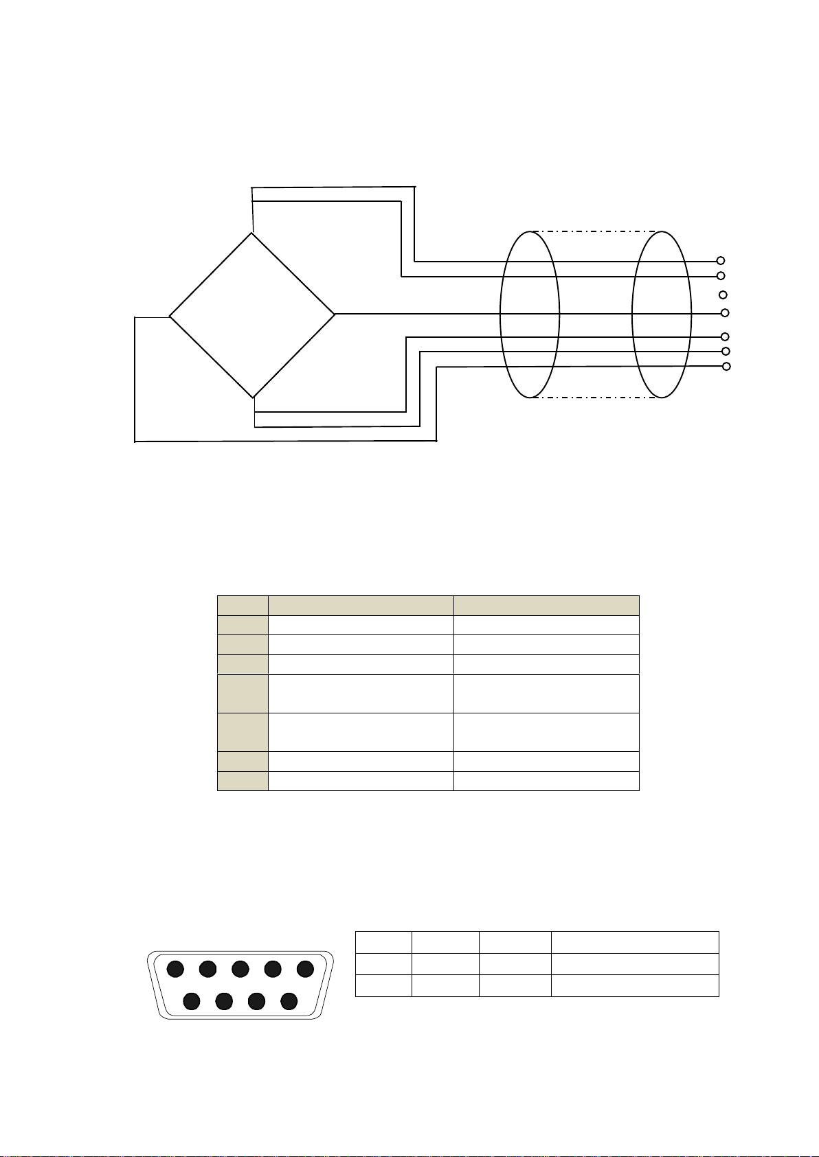
Pin Connection Diagram:
Pin Connection:
RS-232 Connector:
9 pin D-type connector on MI-101 and MI-102, round connector on MI-102s.
Pin
5 Pin Configuration
7 Pin Configuration
1
Signal +
Signal -
2
Signal -
Signal +
3
Shield
Shield
4
Exc Sen -
Exc -
5
Exc +
Sen +
Sen -
6
Sen + 7
Exc +
2
RXD
Input
Receiving data
3
TXD
Output
Transmission data
5
GND ― Signal ground
EXC+
SEN+
SEN-
EXC-
SIG+
SIG-
SHIELD
5
5
3
2
4
4
1
LOAD CELL
Load Cell 5 Pin Diagram
1
2
3 4 5
6 7 8
9
Page 6
- - 3 - -
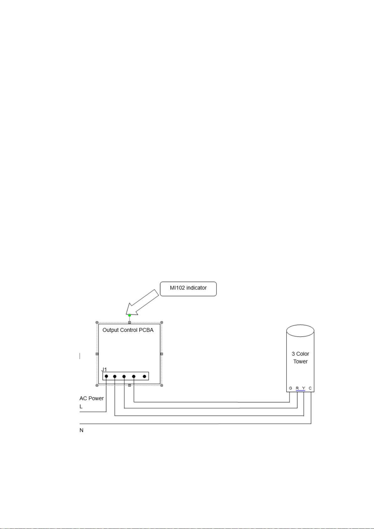
Checkweight Output Diagram:
9 Pin Air Connector
pin1~pin6: checkweighing output
Pin 1 hi (output)
Pin 2 ok (output)
Pin 3 low (output)
Pin 4 beep (output)
Pin 5 vcc (5V output)
Pin 6 com (gnd)
Analog output (MI102and MI102S only)
Pin 7 (+ output to 4 to 20mA/ 0-10V)
Pin 6 (GND output to mA/V)
Pin 8 (GND (-) from the external power)
Pin 9 (+ 10 ~ 24V DC from the external power)
Checkweighing output application sample
(Need an additional output control PCBA)
Page 7

- - 4 - -
Operation
Start up:
To start the device, just press the power button . Please make sure that there
is no weight on the scale or else the scale will be calibrated wrongly. If you want
to enter the settings mode, enter the password now.
Zeroing:
In case the scale is not calibrated to zero, make sure the scale is unloaded and
press the Zero button.
Taring:
Taring is zeroing the display when a weighing instrument is loaded. This allows
the weight readout of an empty container to be reset to zero and the net weight
to be read after filling the container.
To use the taring option, turn on the indicator and let it self-calibrate. When the
device is ready for use, place the empty container on the scale and press the
TARE button. The scale will then reset to zero. After this, the scale will display
the net weight. To cancel the TARE weight, empty the scale and press the Zero.
Accumulated Weight:
This function is used to measure the total weight of a group of items individually
and then display the total weight at the end.
To use this function turn the scale on and let it self-calibrate. When this is done,
place the weight that you want to measure on the scale. When the stable symbol
is shown on the indicator, press the M+ button on the screen to save the weight.
Do this to all the weights that you would like to measure. At the end, press the
MR button to show the accumulated weight.
To clear the accumulated weight, press M+ and MR together.
Page 8

- - 5 - -
Check Weighing:
This function allows you to set a high and low range value into the indicator’s
memory. When a unit being measured is not in this range an audible alarm is
sounded to notify you. This function can be used effectively for quality control
procedures.
To set the value for the high and low range, start the machine and let it calibrate
itself. When the machine is fully calibrated press G/N and Print together. This
will display “Set H” on the screen. Pressing Zero (enter) will let you set the high
limit or press TARE (next) to select a different option.
To set the higher limit, press Zero. This is confirmed by a red light next to the
word ‘HI’ which will turn on. Then use the MR to move right and the M+ to move
left. The TARE key can be used to increment the number. To enter 65.5kg press
M+ once and then press TARE five times till the number 5 is shown. Then press
M+ once more and then press TARE five times till the number 5 again. Lastly,
press M+ and then press TARE six times till the number 6 is shown. Then press
enter to save the value. This method can also be used to set the lower limit.
To clear the high limit, go into the options and press Print. This will clear the limit.
You can also do this to clear the lower limit.
The beep function is used to set up an audible alarm on the indicator. There are
three different options available.
oH
An alarm is sounded when the weight
of the unit is inside the set range.
nG
An alarm is sounded when the weight
of the unit is outside the set range.
no
No alarm is sounded.
Animal Mode:
When using the scale to measure livestock, animal mode clears fluctuations
caused by movements providing you with a stable reading. To be able to use this
function, animal mode needs to be turned on. This can be done by entering the
settings panel during the warm-up period. Then using the TARE button search
for the “P4 OTH” option and the “Ann” option. Here you can select whether to
enable animal mode.
To use animal mode press TARE and Zero simultaneously. This will cause the
indicator to beep twice and a “HOLD” sign will show up on the screen.
Page 9

- - 6 - -
Keyboard Lock:
This function allows you to lock the keyboard after 10 minutes since the last time
a button was pressed.
To enable this option, you have to enter the setting panel, and make your way
using the TARE button to the “P4 OTH” option and then the “LOCK” option. Here
you can toggle this option on and off.
When the keyboard is not in use, the keyboard is locked and if any key is pressed,
the display will show “K-LCK”. To unlock the keyboard, hold PRINT, MR, ZERO
for two seconds. This will display “ULCK” and will unlock the keyboard.
Backlight:
To adjust the backlight on the indicator, press and hold the ZERO key for 3
seconds. This will cause the display to show “setbl”. Press ZERO to enter
backlight setting. You will have three options to choose from:
bL ON
Backlight always turned on.
bL AU
Auto backlight. This turn on the backlight for only 5 seconds after a
key is pressed.
bL oFF
Turns backlight off
Press the TARE key to select the option you require. Press G/N when you are
finished to take you back to the main screen.
Auto power off:
This function is a power saving function that allows the indicator to automatically
turn off when not in use.
To use this, press and hold ZERO for 3 seconds. The display will then show
“SEtbL”. Then press the TARE key till the display shows “SEtoF” and press
ZERO. You have an option of 0/3/5/15/30 minutes to choose from. When you
have selected your option press TARE to save it. Then press G/N to return back
to the main menu.
Page 10

- - 7 - -
Parameter Settings
To enter settings mode, turn on the indicator and then press Print while the
indicator is calibrating itself. Then press M+ G/N TARE as the password to enter
settings mode.
Settings table:
Functio
n
SubFunctio
n
Description
P0 CHH
Set H
Set Lo
BEEP
This setting can be used to set the parameters for the
check weighing function. To learn to use this follow the
instruction on page 5.
P1 REF
AZN0.
This option is used to set the auto tracking range of the
indicator.
Options: 0 = 0.5d, 1d, 2d, 4d
0AUTO
This option is used to select the auto zero range on
the indicator.
Options : 0%, 2%, 5%, 10%, 20%, 50%, 100%
0RAGE
This option is used to select the manual zero range
when pressing the ZERO key.
Options: 0%, 2%, 4%, 10%, 20%, 50%, 100%
0TARE
This option is used to select the manual zero range
when pressing the ZERO key.
Options: 0%, 2%, 4%, 10%, 20%, 50%, 100%
SPEED
Used to set the ADC speed.
7.5/15/30/60 times/second
ZERO
Shows the load on the load cells in the scale when no
weight is applied on the scale.
P2 Con
Mode
This option is used to set RS-232 communication
mode
Options:
CONT
Continuous send
ST1
send one frame data after stable
STC
send data continuously when
stable
PR1
when print key is pressed, send
one frame data (printer mode)
PR2
when the M+ key is pressed, the
printer will print the current weight
and the accumulated weight at the
same time.
AUTO
auto accumulate (auto print)
mode. When the weight is stable,
the indicator will print the result
and then return to zero
Page 11

- - 8 - -
automatically
ASK
ask mode, bi-direction,
Command R: read data
Command T: TARE
Command Z: zero
Wireless
Wireless mode
Note: If you have selected the wireless model, the
communication mode has to be set to wireless.
BAUD
This option is used to set the baud rate for all comms.
Options: 600/1200/2400/4800/9600
Pr
This option is used to set parity verify
Optional: 7E1/7O1/8N1
ptype
tpup:
Sets the printer as a tpup model.
LP-50:
Set the printer as LP-50 model
lab
“Lab x”, set gross/acc print format
prt
“prt”, set the date/time print format
lang
Select the print language
Options: English, Chinese
P3 CAL
count
The display will show the internal count on the scale.
SHOULD NOT BE ZERO.
dECI
This option is used to select the decimal
Options : 0, 0.0, 0.00, 0.000
Dual
Off
r1lnc
Option used to increment the scale.
Options: 1, 2, 5, 10, 20, 50, 100,
200
Cap1
Sets the maximum capacity that
the scale can take.
On
Do not use this option without consulting
Millennium Mechatronics first.
CAL
This option is used to calibrate the indicator and scale
so that an accurate weight is given. There are two
options for calibration, noLin and LinEr.
noLin:
Non- linear calibration uses only one
weight to calibrate the scale. For
instructions follow the steps on page 9
LinEr:
Linear calibration should be selected if
you want to use multiple weights to
calibrate the scale. This gives a more
accurate reading than a nonlinear
calibration. To see how to calibrate in
linear mode follow the instruction on
page 9.
Gra
This setting lets you adjust the value of gravity
(9.6~10).
P4 OTH
Ann
This function is used to set animal mode on and off. It
is helpful when measuring animals and livestock.
Page 12

- - 9 - -
Instruction on pg 5.
Lock
Is used to turn on and off the key-board lock.
P5 Unt
Sets the unit, when the unit is set as on, then this unit
could be active. Note, Tj and Hj could not be used at
the same time.
P6 xcl
Use this function for external calibration of the scale.
P7 rst
This resets the indicator and all parameters to factory
settings.
P8 uwb
On Bluetooth models, turns the function on/off.
The PS232 cannot be used when Bluetooth mode is
on.
Non-Linear Calibration:
To do a basic (non-linear) calibration of the scale, make your way to the “CAL”
section in the setting menu. Then select “noLin”. The screen will then display
“unLd”. At this point remove any weights on the platform then press the ZERO
key. The scale will then show the last calibration weight used to calibrate the
indicator. If this is not correct use the M+, MR, TARE keys to select the right
weight. When the correct value is entered, press ZERO to confirm and the
display will then display “load”. At this point, load the calibration weight onto the
scale. After the stable sign is displayed, press ZERO to finish calibration.
Please note that the closer this weight is to the max load you expect to measure,
the more accurate your result will be. For example, if the max load that you
expect to measure is 300kg, the closer the calibration weight is to 300kg, the
more accurate the calibration will be.
After calibration, the scale should be checked to verify the calibration and linearity
is correct. If necessary, repeat calibration. Be certain that the scale is stable
before accepting any weight.
Linear Calibration:
Linear calibration allows you to calibrate the scale over a range thus providing a
more accurate calibration. This is done by using a range of calibrating weights.
To use linear calibration, make your way to the “CAL” section in the setting menu.
Then select “LinEr”. Press ZERO to enter calibration. The display will then show
“PIN” at which point press G/N, M+, MR to enter. The display will then show
“Load0” at which point unload any weights on the platform of the scale. When
the stable sign is displayed on the screen, press ZERO to continue.
Page 13

- - 10 - -
The display will then show “Load1”. At this point enter …. . Press ZERO to
continue. The display will then show “Load2”. At this point enter …. . Press ZERO
to continue. The display will then show “Load3”. At this point apply the full
capacity of the weights that you wish to measure. The device will calibrate itself
automatically and then press ZERO to finish the calibration.
If the calibration is acceptable the display will return to normal. If an error
message is shown try calibration again as a disturbance may have prevented a
successful calibration. If the problem persists, contact Millennium Mechatronics
Limited for more support.
After calibration, the scale should be checked to verify the calibration and linearity
is correct. If necessary repeat calibration, especially to be certain the scale is
stable before accepting any weight.
RS-232 Configuration
The MI101/MI102 indicator can be ordered with an optional RS-232 output.
Basic Information
Specifications:
RS-232 output of weighing data
ASCII code
7/8 data bits
Parity selectable
Baud rate from 600bps to 9600bps
2
RXD
Input
Receiving data
3
TXD
Output
Transmission data
5
GND ― Signal ground
1 2 3 4 5
6 7 8
9
Figure 1: Pin Configuration
Page 14

- - 11 - -
Default Print Out
Data Format for normal weighing operations, parts counting or recalling of totals
from memory will each be different. Examples follow:
Normal Output
When recalling the Total weight stored in the accumulation memory the output
format is:
Continuously Output Protocol
con1: weighing mode string setup
,
-/
k g CR
LF
-HEADER1- - HEADER2- --- WEIGHT DATA -- WEIGHT UNIT TERMINATOR
Header1: ST=Stable weight , US=Unstable Weight
Header2: NT= Net , GS=Gross
S/N The number increments every time a new value is stored in memory
GW GW for gross weight, NT for net weight and a unit of weight
<If>
<If> Includes 2 line feeds
*************** A line of stars is shown
<lf> Includes 1 line feed
Total No: 3 Times of the accumulation memory
Total wt.: 0.447KG Weight of the accumulation memory
***************
Page 15

- - 12 - -
Battery Operation
The Indicator can be operated from the battery if desired. The battery life is
approximately 30 hours (MI101) or 80 hours (MI102).
When the battery needs charging a symbol on the weight display will turn on.
The battery should be charged when the symbol is on. The scale will still operate
for about 10 hours after which it will automatically switch off to protect the battery.
To charge the battery plug into the mains power switch. The scale does not need
to be turned on.
The battery should be charged for 12 hours for full capacity.
Just under the quantity display is an LED to indicate the status of battery
charging. When the scale is plugged into the mains power the internal battery
will be charged. If the LED is green the battery has a full charge. If it is Red the
battery is nearly discharged and yellow indicates the battery is being charged.
As the battery is used it may fail to hold a full charge. If the battery life becomes
unacceptable then contact your distributor.
Additional Information
Tpup Information Table:
0 1 2 3
tpup
tpup
tpup
tpup
0
GS: 0.888kg
NT: 0.666kg
TW: 0.222kg
GW: 0.888kg
GS: 0.222kg
TOTAL:
0.222kg
NT: 0.222kg
TW: 0.666kg
GW: 0.888kg
TOTAL:
0.222kg
1
DATE: 04/06/06
GS: 0.888kg
DATE:
04/06/06
NT: 0.666kg
TW: 0.222Kg
GW: 0.888kg
DATE:
04/06/06
GS: 0.222kg
TOTAL:
0.444kg
DATE:
04/06/06
NT: 0.222kg
TW: 0.666kg
GW: 0.888kg
TOTAL:
0.444kg
LAB
TYPE
PRT
Page 16

- - 13 - -
2
TIME: 11/11/11
GS: 0.888kg
TIME: 11/11/11
NT: 0.666kg
TW: 0.222kg
GW: 0.888kg
TIME: 11/11/11
GS: 0.222kg
TOTAL:
0.666kg
TIME: 11/11/11
NT: 0.222kg
TW: 0.666kg
GW: 0.888kg
TOTAL:
0.666kg
3
DATE: 04/06/06
TIME: 11/11/11
GS: 0.888kg
DATE:
04/06/06
TIME: 11/11/11
NT: 0.666kg
TW: 0.222kg
GW: 0.888kg
DATE:
04/06/06
TIME: 11/11/11
GS: 0.222kg
TOTAL:
0.888kg
DATE:
04/06/06
TIME:
11/11/11
NT: 0.222kg
TW: 0.666kg
GW: 0.888kg
TOTAL:
0.888kg
4
NO.: 4
GS: 0.888kg
NO. : 4
NT : 0.666kg
TW: 0.222kg
GW: 0.888kg
NO.: 4
GS: 0.222kg
TOTAL:
1.000kg
No.: 4
NT: 0.222kg
TW: 0.666kg
GW: 0.888kg
TOTAL:
1.000kg
5
DATE: 04/06/06
NO.: 5
GS: 0.888kg
DATE:
04/06/06
NO.: 5
NT: 0.666kg
TW: 0.222kg
GW: 0.888kg
DATE:
04/06/06
NO.: 5
GS: 0.222kg
TOTAL:
1.222kg
DATE:
04/06/06
No.: 5
NT: 0.222kg
TW: 0.666kg
GW: 0.888kg
TOTAL:
1.222kg
6
TIME: 11/11/11
NO.: 6
GS: 0.888kg
TIME: 11/11/11
NO.: 6
NT: 0.666kg
TW: 0.222kg
GW: 0.888kg
TIME:
11/11/11
NO.: 6
GS: 0.222kg
TOTAL:
1.444kg
TIME: 11/11/11
No.: 6
NT: 0.222kg
TW: 0.666kg
GW: 0.888kg
TOTAL:
1.444kg
7
DATE: 04/06/06
TIME: 11/11/11
NO.: 7
GS: 0.888kg
DATE:
04/06/06
TIME: 11/11/11
NO.: 7
NT: 0.666kg
TW: 0.222kg
GW: 0.888kg
DATE:
04/06/06
TIME:
11/11/11
NO.: 7
GS: 0.222kg
TOTAL:
1.666kg
DATE:
04/06/06
TIME: 11/11/11
No.: 7
NT: 0.222kg
TW:: 0.666kg
GW: 0.888kg
TOTAL:
1.666kg
Page 17

- - 14 - -
LP-50 Information Table:
0 1 2
3
LP-50
LP-50
LP-50
LP-50
0
2000/00/00
00:00
S/N 1
GW 0.888kg
As left
As left
As left
1
DATE:
2000/00/00
TIME: 00:00
GW: 0.888kg
As left
As left
As left
2
DATE:
TIME: 00:00
S./NO.: 2
GROSS WT:
0.888kg
As left
As left
As left
3
2000/00/00
00:00
S/N 0003
GW 0.888kg
As left
As left
As left
4
2000/00/00
00:00
S/N 4
GW 0.888kg
As left
As left
As left
5
DATE:
2000/00/00
TIME: 00:00
GW: 0.888kg
As left
As left
As left
6
DATE:
TIME: 00:00
S./NO.: 6
GROSS WT:
0.888kg
As left
As left
As left
7
2000/00/00
00:00
S/N 7
GW 0.888kg
As left
As left
As left
LAB
PRT TYPE
Page 18

- - 15 - -
Error Codes
ERROR
CODES
DESCRIPTION
RESOLUTION
- - - - -
Over range
Remove weight from the scale.
If the problem persist contact Meltrons
for assistance.
Err 4
Zero Setting
Error
The scale was outside the normal zero
setting range either when it was turned
on or when the ZERO key was pressed.
Remove weight from the scale and try
again.Use the TARE key to set the
display to zero value.
If the problem persist contact your dealer
for assistance.
Err 6
A/D out of range
The values from the A/D converter are
outside the normal range. Remove
weight from the scale if overloaded,
make sure the pan is attached.
Indicates the load cell or the electronics
may be faulty.
If the problem persist contact your dealer
Page 19

- - 16 - -
Millennium Mechatronics Limited
55F Richard Pearse Drive
Airport Oaks
Manukau
Auckland 2022
New Zealand
Phone:
+64 9 6220808 (Overseas)
09 622 0808 (New Zealand)
0800 MELTRONS (From New Zealand)
Email:
info@meltrons.com
 Loading...