

Millennial Net MeshScape Wi-Stat IIIp-S Product Manual

MeshScape®
Energy Management Solution
Standalone Programmable Pneumatic
DocumentNumber: 2012‐PM‐EM‐6424020V2v003
Revision: 03
Released: April2012
Wi-Stat IIIp-S
Thermostat
Product Manual

Wi-Stat IIIp-S Wireless Pneumatic Thermostat Product Manual
CONTENTS
1.0
DOCUMENT OVERVIEW..........................................................3
2.0 WI-STAT IIIP-S OVERVIEW ......................................................3
2.1 HVAC OPERATION ..................................................................................................................3
2.2 OPERATING PRINCIPLE OF WI-STAT IIIP-S PNEUMATIC THERMOSTAT ...................................................4
2.3 STANDALONE OPERATION .........................................................................................................5
2.3.1 Standalone Wi-Stat IIIp-S Operational Modes.................................................................5
2.3.2 Standalone Wi-Stat IIIp-S Occupancy Programming .......................................................6
2.3.3 Standalone Wi-Stat IIIp-S Occupancy Programming Examples .......................................7
2.4 WIRELESS DDC OPERATION.......................................................................................................8
2.4.1 Wireless DDC Wi-Stat IIIp-S Operational Modes..............................................................8
2.4.2 Fail-Safe Features ...........................................................................................................9
2.5 OPTIONAL MOTION SENSOR FUNCTION ......................................................................................11
2.6 WIRELESS DDC WI-STAT IIIP-S CONFIGURATION PARAMETERS .......................................................12
2.7 TECHNICAL WI-STAT IIIP-S SPECIFICATIONS.................................................................................15
3.0 WI-STAT IIIP-S CONFIGURATION ...........................................17
3.1 WI-STAT IIIP-S CONFIGURATION STEPS ......................................................................................17
3.2 WI-STAT IIIP-S CONFIGURABLE SETTINGS ...................................................................................17
3.3 WI-STAT IIIP-S CONFIGURATION MODE .....................................................................................18
3.4 CONFIGURATION FROM STANDALONE TO WIRELESS DDC...............................................................19
3.5 PROGRAMMING SCHEDULE ON A STANDALONE WI-STAT IIIP-S .......................................................20
3.6 HVAC MODE SCREEN............................................................................................................22
3.7 FAN MODE SCREEN................................................................................................................22
3.8 MAINTENANCE – PNEUMATIC SETTINGS .....................................................................................23
4.0 WI-STAT IIIP-S INSTALLATION...............................................26
4.1 LIST OF TOOLS AND HARDWARE NEEDED FOR INSTALLATION...........................................................26
4.2 ELECTROSTATIC SENSITIVE DEVICES (ESD) SAFETY MEASURES .........................................................26
4.3 CLEAN AIR REQUIREMENT .......................................................................................................26
4.4 WI-STAT IIIP-S ORDER OF INSTALLATION ....................................................................................27
4.5 WI-STAT IIIP-S INSTALLATION STEPS..........................................................................................28
5.0 WI-STAT IIIP-S OPERATION ...................................................31
5.1 LCD DISPLAY .......................................................................................................................32
5.2 A
5.3 U
5.4 U
DJUSTING ROOM TEMPERATURE..............................................................................................33
SING OVERRIDE MODE BUTTON .....................................................................................34
SING SHOULDER MODE BUTTON .....................................................................................34
Page 2 of 36 2012-PM-EM-6424020V2v003 Millennial Net, Inc.
Wi-Stat IIIp-S Wireless Pneumatic Thermostat Product Manual
1.0 Document Overview
This document summarizes the operation of the Wi-Stat IIIp-S pneumatic thermostat for HVAC
monitoring and control purposes. It provides details of use cases and the overall solution that will
be delivered to meet the needs of supported HVAC applications.
2.0 Wi-Stat IIIp-S Overview
2.1 HVAC Operation
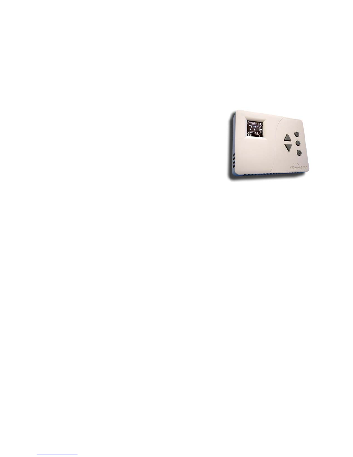
The Wi-Stat IIIp-S wireless pneumatic thermostat is an intelligent
energy conservation device that provides remote zone
monitoring and control for commercial, industrial, and municipal
HVAC environments. It can work as a stand alone
Weekday/Weekend programmable thermostat or can be
converted to wireless DDC thermostat. As a stand alone
programmable thermostat Wi-Stat IIIp-S can independently
operate on user configurable Weekday/Weekend schedule.
If converted to wireless DDC (see Section 2.3 Standalone
Operation) Wi-Stat IIIp-S enables local temperature controls
within the range set by company-wide energy policy rules, bidirectionally communicated via a mesh network to and from a
remote monitoring and control application. It is an electronic
pneumatic wireless thermostat for intelligent room temperature control in heating and air
conditioning applications.
Designed to replace existing manual pneumatic thermostats, the Wi-Stat IIIp-S provides Direct
Digital Control features, such as remote wireless setpoint control and occupancy scheduling,
continuous room temperature, branch line pressure and battery status monitoring, all of which
were previously unavailable in pneumatic HVAC systems. The innovative design of Wi-Stat IIIp-S
completely reshapes pneumatic HVAC controls - the controller does not utilize any mechanical
parts. A solid state temperature sensor replaces bi-metallic strip elements for precise room
temperature monitoring and the advanced Piezo electric valve actuator replaces mechanical
valve for improved branch line pressure control. These advanced technologies guarantee longer,
more dependable and maintenance-free operation.
Wi-Stat IIIp-S operation is regulated by a number of operational modes which can be triggered
scheduled times. Each mode is designed to optimize energy use under certain conditions and
has a set of rules that will manage HVAC equipment operation and restrict local thermostat
requests. All Wi-Stat IIIp-S variable configuration, management and mode scheduling is done
remotely using a monitoring and control software application.
There are two types of Operational Modes – Scheduled and Manual. Scheduled Modes are
triggered by occupancy schedules and provide energy savings by aligning HVAC operation to
actual building occupancy. Manual Modes can only be initiated by the user at the Wi-Stat level.
They are used to adjust HVAC operation manually outside of the schedule, but within set energy
policy parameters.
Figure 1. Wi-Stat IIIp-S Wireless
Pneumatic Thermostat
Page 3 of 36 2012-PM-EM-6424020V2v003 Millennial Net, Inc.
Wi-Stat IIIp-S Wireless Pneumatic Thermostat Product Manual
2.2 Operating Principle of Wi-Stat IIIp-S pneumatic thermostat
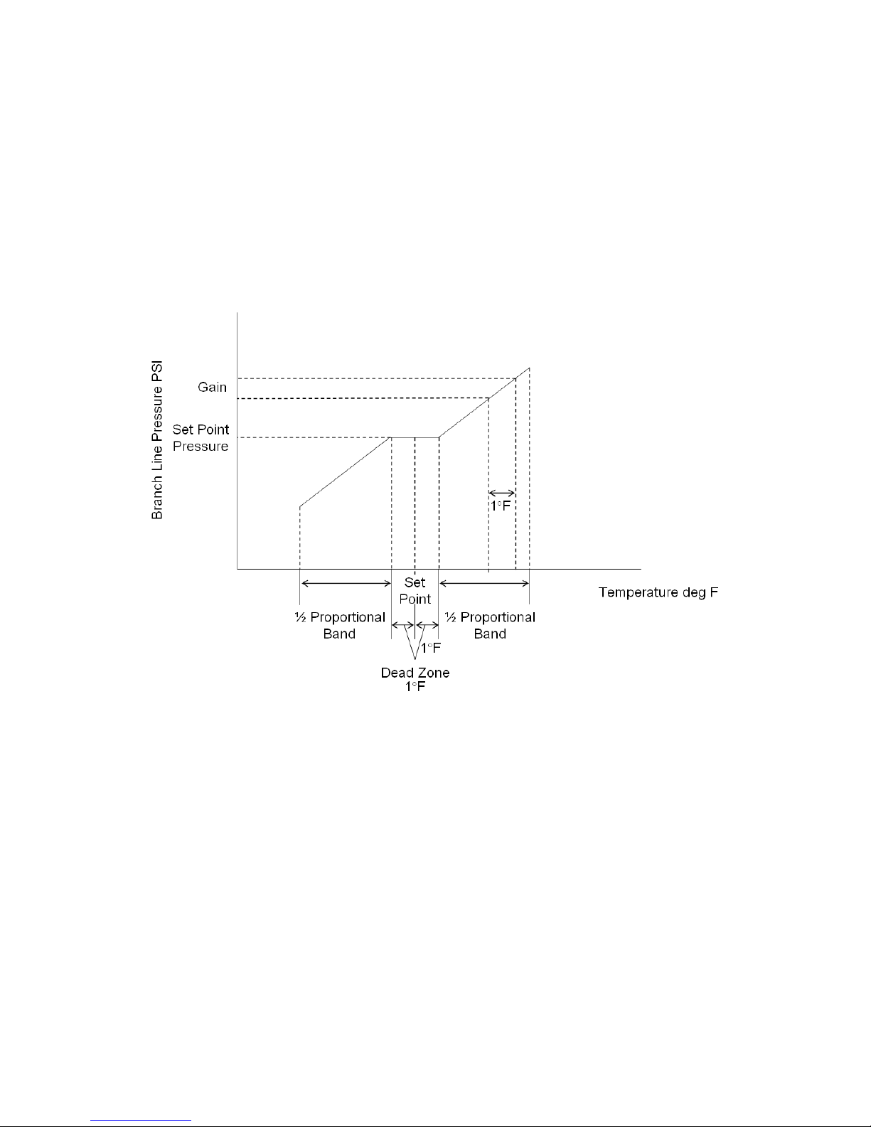
Wi-Stat IIIp-S has been designed to support any 0 ~ 22 PSI pneumatic HVAC control systems.
Variation in branch line pressure is proportional to deviation of room temperature from Set Point;
the proportional factor is determined by the Gain, which is defined as the change in branch line
pressure in PSI in response to a 1°F change in room temperature.
Figure 2 below shows the linear relationship between branch line pressure and room temperat ure
at a given Set Point for Direct Acting Thermostat configuration (for Reverse Acting the graph
would be flipped horizontally).
A direct acting system is shown in Figure 2 where Wi-Stat IIIp-S will increase branch line
pressure in response to an increase in room temperature. When room temperature is within the
Dead Zone (default ±1°F) around the Set Point, branch line pressure is regulated at Set Point
Pressure, and the pneumatic actuator will be at the minimum heat, cool or neutral position. When
room temperature rises above Set Point plus Dead Zone, branch line pressure will increase i n
proportion to temperature increase, with proportional factor defined by the Gain value. On the
other hand, if room temperature decreases below Set Point minus Dead Zone, branch line
pressure will decrease in proportion to temperature decrease. The proportional band defines the
temperature range where branch line pressure changes in proportion to temperature change.
Note that Set Point Pressure, Dead Zone, Gain, and Proportional Band can be adjusted using the
menu buttons on Wi-Stat IIIp-S or within the Wi-EMS web application.
Page 4 of 36 2012-PM-EM-6424020V2v003 Millennial Net, Inc.
Figure 2. Temperature - Pressure Profile

Wi-Stat IIIp-S Wireless Pneumatic Thermostat Product Manual
2.3 Standalone Operation
This section outlines Wi-Stat IIIp-S operation and programming when configured as a
standalone device.
2.3.1 Standalone Wi-Stat IIIp-S Operational Modes
Scheduled Modes:
The following operational modes are regulated by the Schedule programmed on the device.
o Occupied Mode – Occupancy mode is used when the zone is scheduled to be occupied.
The room temperature during this mode will be adjusted by people in the room by
pressing Up and Down buttons. Wi-Stat IIIp-S allows manual temperature control ±14F
around programmed set point (28F total range). Users will be able to program set point
during programming the device (see instruction below). Range cannot be changed.
For example, if the Set Point value is 70°F, people in the room will be able to change
temperature manually between 56° and 84° F.
o Unoccupied Mode – Energy saving mode for the times when rooms are unoccupied.
Temperature in the zone will controlled by Upper and Lower limits - when the room
temperature is between the upper and lower Unoccupied Mode temperature limits the WiStat IIIp-S will not call for heat or cool. If the temperature will fall outside the Unoccupied
Mode upper and lower temperature range, the Wi-Stat IIIp-S will control the HVAC
system accordingly to bring the environment back into range. Upper and lower limits are
programmable (see instructions below)
Manual Modes:
The following modes cannot be programmed. They can only be initiated locally by the user
interfacing with the Wi-Stat IIIp-S.
o Override Mode – manual mode will turn Wi-Stat IIIp-S to occupied mode. Can only be
initiated by the user by pressing the Override button on the Wi-Stat IIIp-S. Override
has limited 2 hour duration time; after it expires, the Wi-Stat IIIp-S returns to its regularly
scheduled mode. The Override Mode overrides the scheduled Occupied or Unoccupied
Mode by allowing the user to control the HVAC system through the local thermostat. If
the room temperature is outside the Override Comfort Zone range, the Wi-Stat IIIp-S will
disable local thermostat controls. Override Mode overrules your Energy Policy, so
always check with your administrator before using it.
o Shoulder Mode – Energy Saving transition from occupied to unoccupied modes. It can
be triggered locally at the Wi-Stat IIIp-S level by pressing Shoulder button - . While
in Shoulder mode, Wi-Stat IIIp-S will not call for heat or cool when the room temperature
is ± 5F within the set point. It is used to set back the room temperature set point
manually if occupants leave the facility earlier than the scheduled time, essentially
overriding the current schedule until the next scheduled mode change occurs. For
example, if a zone is running a five-day, 8AM to 6PM occupancy schedule, but one day
occupants are leaving at 2PM, they can manually set the zone into shoulder mode at
2PM. The Wi-Stat IIIp-S will remain in Shoulder mode until 6PM and then will follow its
regular schedule.
Page 5 of 36 2012-PM-EM-6424020V2v003 Millennial Net, Inc.
Wi-Stat IIIp-S Wireless Pneumatic Thermostat Product Manual
2.3.2 Standalone Wi-Stat IIIp-S Occupancy Programming
This section outlines how scheduling module operates when Wi-Stat IIIp-S configured as a
standalone device. For schedule step-by-step programming instructions please refer to
the part 3.5 Programming Schedule on a Standalone Wi-Stat IIIp-S
Wi-Stat IIIp-S is equipped with independent time clock and can be programmed with
Weekday/Weekend occupancy schedule. Complete 7 day schedule consists of two autonomous
components:
Weekday Schedule – Monday through Friday
Weekend Schedule – Saturday and Sunday
Each component is split into two parts to be schedule as occupied or unoccupied mode:
Weekday 1
Weekday 2
Weekend 1
Weekend 2
To accommodate for daytime or nighttime shift schedules, each part can be configured to
occupied or unoccupied mode independently.
For each Occupied Mode following features can be configured:
Occupied mode start time
Temperature set point value – people will be able to adjust temperature by ±14F around it.
For each Unoccupied Mode following features can be configured:
Unoccupied mode start time
Upper Temperature limit
Lower Temperature limit (Thermostat will be off while temperature is within these limits)
Start time of each schedule part is automatically an end time of the previous one. (i.e. for 6am –
6pm occupied schedule occupied mode to start at 6am and unoccupied at 6pm). Figures below
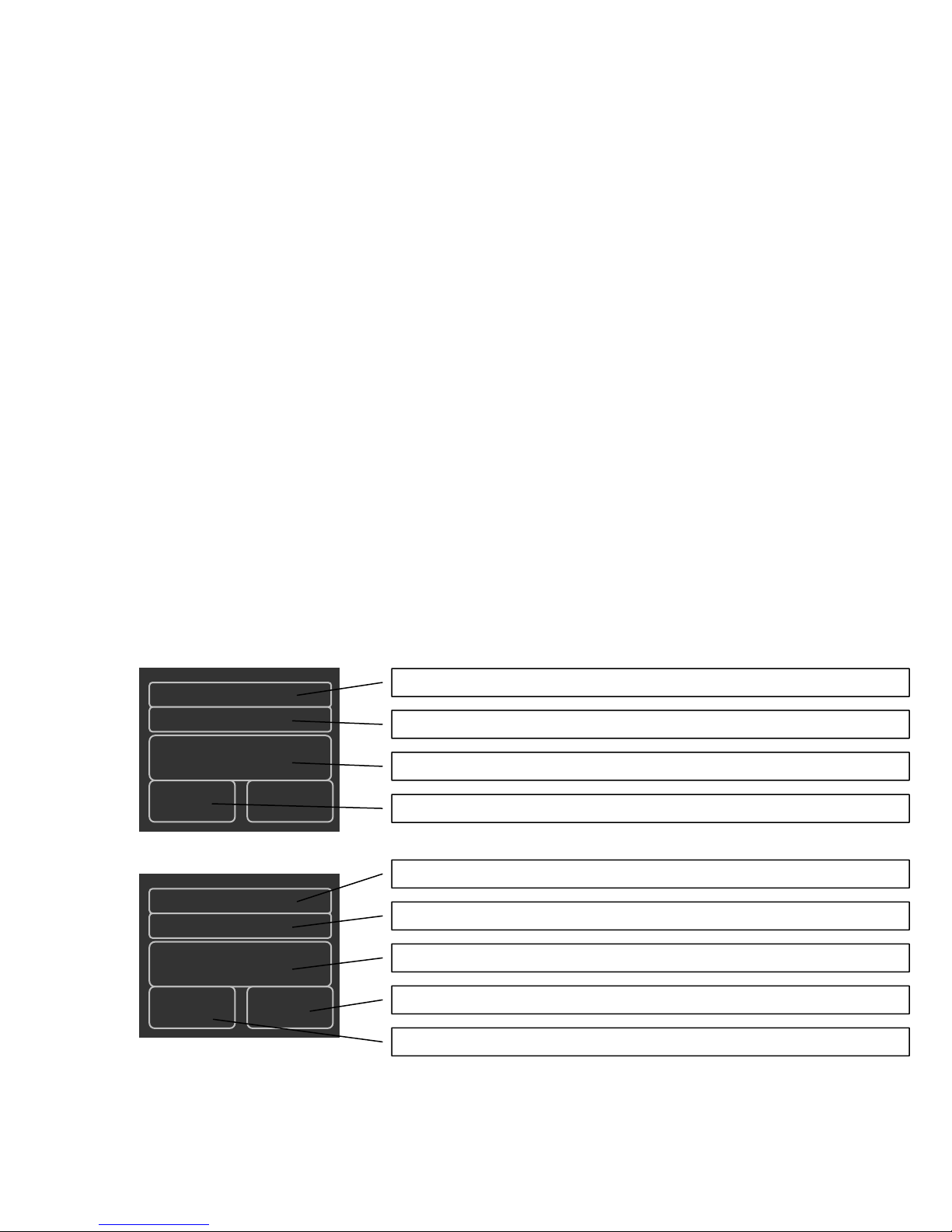
illustrate Occupied and Unoccupied schedule setup screens.
Weekday 1
Occupied
07:00
70
Weekday 2
Figure 3. Wi-Stat IIIp-S Schedule Setup Screen for Occupied mode
Weekday 1, Weekday 2, Weekend 1 or Weekend 2. Defines which part you are editing
Occupied or Unoccupied. Defines occupancy mode of that part
Time (24h format). Defines start time of that part
Set point Temperature. Defines Occupied mode set point temperature of that part
Weekday 1, Weekday 2, Weekend 1 or Weekend 2. Defines which part you are editing
Occupied or Unoccupied. Defines occupancy mode of that part
Unoccupied
18:00
85 55
Figure 4. Wi-Stat IIIp-S Schedule Setup Screen for Unoccupied mode
Time (24h format). Defines start time of that part
Lower Temperature Limit. Defines Unoccupied mode lower temperature limit for that part
Upper Temperature Limit. Defines Unoccupied mode upper temperature limit for that part
For schedule step-by-step programming instructions please refer to the part 3.5 Programm ing
Schedule on a Standalone Wi-Stat IIIp-S
Page 6 of 36 2012-PM-EM-6424020V2v003 Millennial Net, Inc.
Wi-Stat IIIp-S Wireless Pneumatic Thermostat Product Manual
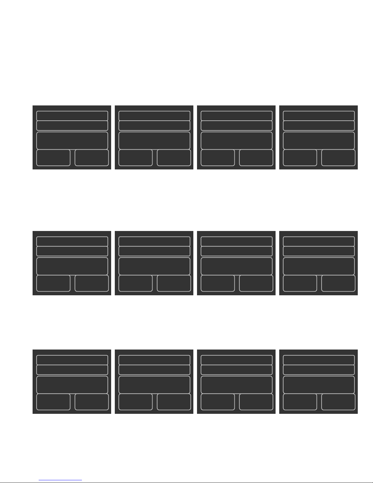
2.3.3 Standalone Wi-Stat IIIp-S Occupancy Programming Examples
Standard Office Hours
Set point - 70F
Occupied from 9am to 5pm Monday to Friday
Saturday and Sunday – unoccupied, upper limit - 85F, lower - 55F.
Program Wi-Stat IIIp-S Schedule Setup Screens:
Weekday 1
Occupied
09:00
70
*Start and end time are irrelevant; both weekend parts are set to the same unoccupied mode.
Night Shift Hours
Weekday 2
Unoccupied
17:00
85 55
Weekend 1
Unoccupied
09:00*
85
55
Weekend 2
Unoccupied
17:00*
85
55
Set point - 70F
Occupied from 3pm to 6am 7 days a week
Program Wi-Stat IIIp-S Schedule Setup Screens:
Weekday 1
Unoccupied
06:00
85 55
Extended Office Hours w/ Weekend Schedule
Set point - 70F
Occupied from 8am to 6pm Monday to Friday
Occupied from 10am to 1pm Saturday and Sunday.
Program Wi-Stat IIIp-S Schedule Setup Screens:
Weekday 1
Occupied
08:00
70
For schedule step-by-step programming instructions please refer to the part 3.5 Programm ing
Schedule on a Standalone Wi-Stat IIIp-S
Weekday 2
Occupied
15:00
70
Weekday 2
Unoccupied
18:00
85 55
Weekend 1
Unoccupied
06:00
85
Weekend 1
Occupied
10:00
70
55
Weekend 2
Occupied
15:00
70
Weekend 2
Unoccupied
13:00
85
55
Page 7 of 36 2012-PM-EM-6424020V2v003 Millennial Net, Inc.

Wi-Stat IIIp-S Wireless Pneumatic Thermostat Product Manual
2.4 Wireless DDC Operation
This section is only applicable if Wi-Stat IIIp-S is being used as wireless DDC device.
Configured as a standalone programmable device it will not communicate data wirelessly.
Wi-Stat IIIp-S can operate as a wireless thermostat designed to monitor and control pneumatic
HVAC systems as part of the overall Millennial Net Wireless Energy Management Solution. Wi-
Stat IIIp-S is equipped with 2.4GHz IEEE 802.15.4 radio and can communicate via MeshScape®
mesh network protocol. The wireless mesh network forms itself and data communications enable
remote monitoring, adjustment and trending to ensure long term performance. It communicates
data over the wireless network in conjunction with other wireless Millennial Net devices. In the
wireless mesh network Wi-Stat IIIp-S operates as a battery-powered end node. When installed in
buildings with common sheetrock walls, its nominal radio communi cation range is approximately
200 feet. However, if the Wi-Stat IIIp-S is located more than 200 feet from the Wi-Site network
controller, Wi-Routers must be deployed to relay data generated by the Wi-Stat IIIp-S back to the
network controller. Being an end node, Wi-Stat IIIp-S does not support routing function to relay
data for other devices in the mesh network. It communicates with the wireless mesh network as
an individual device that transmits and receives its own data only, to and from the Wi-Site
network controller or through other routing devices,
The first step of the installation process is planning the layout of devices on the building’s floor
plan, including the identification of desired locations for all Wi-Stat IIIp-S devices as well as the
Wi-Site network controller. Measure the radial distances between the Wi-Stat IIIp-S devices and
the Wi-Site network controller to determine if the Wi-Stat IIIp-S devices are within 200 feet of the
Wi-Site. If not, Wi-Routers must be installed to relay signals between the Wi-Stat IIIp-S and the
Wi-Site. The ideal installation provides each end node device, Wi-Stat IIIp-S, with at least two
routes of transmission to the Wi-Site to ensure signal transmission success. Nominal
transmission range of Wi-Routers in common buildings is 300 feet. To ensure complete coverage
of a wireless mesh network, there should be at least two Wi-Routers or one Wi-Router and the
Wi-Site located within a 300 foot radius of every Wi-Stat IIIp-S.
2.4.1 Wireless DDC Wi-Stat IIIp-S Operational Modes
Scheduled Modes:
The following operational modes are regulated by the HVAC Schedule as defined by the user.
Schedules can be set well in advance through a monitoring and control software application and
Wi-Stat IIIp-S will execute them automatically.
o Occupied Mode – Occupancy mode is used when the zone, or room, is scheduled to be
occupied. The room temperature during this mode is defined by two values: Set Point
(the targeted room temperature for the season) and Comfort Zone (the optimal
temperature range around the Set Point). Both values are set by the Energy Policy and
the Wi-Stat IIIp-S will maintain the room temperature within the Comfort Zone. If the
temperature in the room falls outside of the Comfort Zone range, Wi-Stat IIIp-S will react
accordingly and will automatically request to heat or cool. To enhance user compliance
with the Energy Policy, Wi-Stat IIIp-S will allow users to adjust the room temperature
using the local thermostat, as long as the desired temperature is within the range of the
Comfort Zone. If the user requests heat or cool outside of the set Comfort Zone, the
request at the local thermostat will be overwritten by the Energy Policy. For example, the
Set Point value is 70° F and the Comfort Zone Delta is 3° F. The user will only be able to
affect the temperature manually between 67° and 73° F.
o Unoccupied Mode – Energy saving mode for the times when rooms are unoccupied.
When the room temperature is between the upper and lower Unoccupied Mode
temperature limits the Wi-Stat IIIp-S will not call for heat or cool. If the temperature falls
outside the Unoccupied Mode upper and lower temperature range, the Wi-Stat IIIp-S will
control the HVAC system accordingly to bring the environment back into range.
Page 8 of 36 2012-PM-EM-6424020V2v003 Millennial Net, Inc.

Wi-Stat IIIp-S Wireless Pneumatic Thermostat Product Manual
Manual Modes:
The following modes cannot be scheduled or triggered remotely. They can only be initiated
locally by the user interfacing with the Wi-Stat IIIp-S.
o Override Mode – manual mode – can only be initiated by the user by pressing the
Override button on the Wi-Stat IIIp-S. Override has a limited duration time, set by
the Energy Policy; after it expires, the Wi-Stat IIIp-S returns to its regularly scheduled
mode. The Override Mode overrides the scheduled Occupied or Unoccupied Mode by
allowing the user to control the HVAC system through the local thermostat and permits a
wider Comfort Zone range. If the room temperature is outside the Override Comfort Zone
range, the Wi-Stat IIIp-S will disable local thermostat controls. The Override Mode
Comfort Zone range and Override duration time are set by the Energy policy. Override
Mode overrules your Energy Policy, so always check with your administrator
before using it.
o Shoulder Mode – Energy Saving transition from occupied to unoccupied modes. It can
be triggered locally at the Wi-Stat IIIp-S level by pressing Shoulder button - . While
in Shoulder mode, Wi-Stat IIIp-S will not call for heat or cool when the room temperature
is between Upper and Lower Shoulder mode temperature limits. It is used to set back
the room temperature set point manually if occupants leave the facility earlier than the
scheduled time, essentially overriding the current schedule until the next scheduled mode
change occurs. For example, if a zone is running a five-day, 8AM to 6PM occupancy
schedule, but one day occupants are leaving at 2PM, they can manually set the zone into
shoulder mode at 2PM. The Wi-Stat IIIp-S will remain in Shoulder mode until 6PM and
then will follow its regular schedule. Shoulder mode can also be utilized as a Demand
Response mode and can be triggered remotely from the monitoring and control
application.
All parameter-defining rules of each mode are configurable. Please see the “Wi-Stat IIIp-S
Configuration Parameters” table below, in section 2.6.
2.4.2 Fail-Safe Features
Wi-Stat IIIp-S has a number of programmed fail-safe features to ensure continuous HVAC
operation. In the event of communication failure with servers, wireless network, or HVAC
equipment:: a fail-safe mechanism will ensure devices continue to operate in a logical fashion
without diverging into extensive failure. When failure condition no longer exists, the device will
recover from safe mode and resume normal operation.
• Server communication failure – Site Controller (communicant device between Wi-
Stat IIIp-Ss and the server) cannot receive latest commands or send data to the
server
In instances when the Wi-Site fails to communicate with the server, the Wi-Site will
continue to use the 7-day schedule stored in its memory (assuming a schedule is used)
and all Wi-Stat IIIp-Ss will continue controlling HVAC equipment accordingly. During
server communication failure, Wi-Site will continue to log data from the wireless network
until its flash memory is full. Data will no longer be logged once the memory is full
however; when communication is restored, Wi-Site will be able to send all archived data
to the server and receive the updated schedule from the server.
• Wi-Stat IIIp-S loses radio communication with Site Controller
Should the Wi-Stat IIIp-Ss experience radio communication failure with the Wi-Site, WiStat IIIp-Ss will follow default single day schedules, preset on the Wi-Stat IIIp-S. Wi-Stat
IIIp-S has a built in real time clock (RTC) which is synchronized with the wireless mesh
network, therefore, it can operate with a default, hard-coded day schedule even when it is
Page 9 of 36 2012-PM-EM-6424020V2v003 Millennial Net, Inc.

offline. When Wi-Site comes back online, the Wi-Stat IIIp-Ss will automatically receive
updated mode status, Set Point values and other configuration commands based on the
latest user schedule.
• Protection Zone
To protect building infrastructure, equipment, and occupants, Wi-Stat IIIp-S has extreme
temperature limits (configurable by Administrator) that will allow temperatures to float
independently from any mode settings. If these limits are reached, Wi-Stat IIIp-S will
automatically react and adjust Heat or Cool, no matter what scheduled mode is running.
Default value for Upper bound is 95° F, and the Lower bound default value is 40° F.
Wi-Stat IIIp-S Wireless Pneumatic Thermostat Product Manual
Page 10 of 36 2012-PM-EM-6424020V2v003 Millennial Net, Inc.
Wi-Stat IIIp-S Wireless Pneumatic Thermostat Product Manual
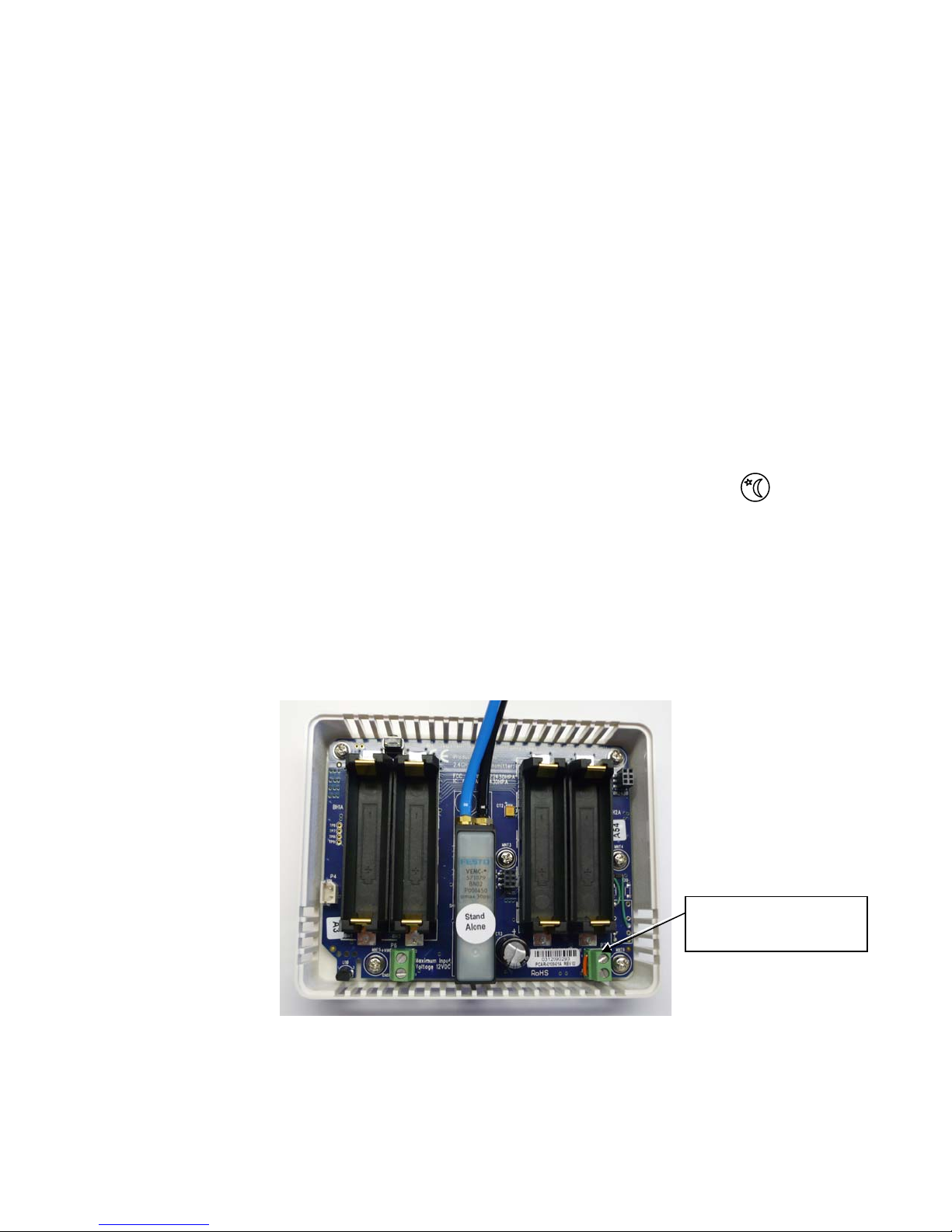
2.5 Optional Motion Sensor Function
The Wi-Stat IIIp-S supports motion sensor function where Wi-StatIIIp-S will automatically go into
Shoulder Mode (refer to Section 2.3.1 Standalone Wi-Stat IIIp-S Operational Modes) to save
energy when no motion is detected for a configurable period of time. Motion sensors with dry
contact signals can be connected to the motion sensor screw terminals of the Wi-Stat IIIp-S.
Upon detecting motion, the motion sensor should “make” the connection for longer than 30
seconds for Wi-Stat IIIp-S to confirm valid motion detection. The default value of motion detection
grace period is 30 minutes, and can be changed through Modbus or BACnet interface, with
minimum 30 minutes and maximum 100 minutes. Please refer to Wi-Stat IIIp-S BACnet object list
for details. If no motion is detected for more than the grace period, and it is in schedule occupied
mode, Wi-Stat3p will go into shoulder mode. Wi-Stat IIIp-S goes into shoulder mode only du ring
schedule occupied periods. Shoulder mode will not be activated while the device is in unoccupied
periods.
There are several means for Wi-Stat IIIp-S to exit shoulder mode:
Motion detection – Wi-Stat IIIp-S goes back to occupied mode if motion is detected and the
device schedule is in occupied mode.
Shoulder mode button press – while in shoulder mode, if the shoulder mode button is
pressed.
Override mode button press – while in shoulder mode, if the override mode button (button
with a sun icon) is pressed.
Schedule change – if schedule changes from occupied to unoccupied then Wi-Stat IIIp-S will
go into unoccupied mode.
To disable the motion sensor function, a jumper wire must be connected to the motion sensor
screw terminals, which effectively simulates motion detection and therefore Wi-Stat3p will not go
into shoulder mode due to lack of motion.
Figure 4. Wi-Stat IIIp-S Firmware Version Screen
Motion Sensor
Connection / Jumper
Page 11 of 36 2012-PM-EM-6424020V2v003 Millennial Net, Inc.
 Loading...