

Millennia LOCi Owner's Manual

Millennia
Millennia Media, FPC
4600 Missouri Flat Road
Placerville, CA 95667
http://www.mil-media.com
(530) 647-0750
Fax (530) 647-9921
Music & Media Systems
Owner’s Manual
Jf010715
LOCi
Universal Playback Equalizer
Phono Preamplifier

Page 2 of 16
Millennia Media, FPC
4600 Missouri Flat Road, Suite 11
Placerville, CA 95667
http://www.mil-media.com
(530) 647-0750
Fax (530) 647-9921
READ THIS FIRST!
Any changes or modifications not expressly
approved by MILLENNIA MEDIA, FPC could void
your authority to operate this equipment unde r
the EC or FCC rules.
1. Copyright: You acknowledge that no title to
the intellectual property in the LOC i is
transferred to you.
2. Inspection: Inspect packing box(es), LOCi,
and cable(s) for damage, unusual marks, or
shortages. It is your responsibility to repor t
damage, shortage, or misshipments in a time ly
manner. Millennia Media and/or its dealer s will
not be responsible for claims arising from
damage in shipping, nor will claims for shortage
or misshipments be honored, more than 10 days
after ship date.
3. Read this manual carefully and completely
before attempting to use the LOCi. Improper
operation could result in damage to product. It
is the user's responsibility to unders tand the
safe use and operation of this device.
4. The shipping box of the LOCi system will
include (1) Owner's Manual, (2) LOCi, (3) a UL
approved power cord (Canada and US units
only), (4) Owner's Registration Card . Fill out the
Owner's Registration Card and return to
Millennia Media at your earliest ability.
The material contained in this manual consis ts of
information that is property of Millennia Media,
FPC and is intended solely for use by the
purchasers of the equipment described in this
manual. Millennia Media, FPC expressly prohibits
the duplication of any portion of this manual or
the use thereof for any purpose other than the
operation and/or maintenance of the eq uip ment
described in this manual without the express
written permission of Millennia Med i a, FPC .
Under copyright laws, this manual may not be
duplicated in whole or in part without the written
consent of Millennia Media, FPC.
LOCi and Analog Legacy are trademarks of
Millennia Media, FPC with all rights res er ved. All
other trademarks herein are property of their
respective holders. Serial numbers are located
on the left side of each unit.
SAFETY PRECAUTIONS
For your safety and the safety of others, be sure
to read and understand all safety and
operational instructions bef ore atte mpting to use
the LOCi. WARNING: The LOCi internal circuitry
carries lethal voltages. Caref ully ob s erve all
warnings, precautions, and instruc ti o ns on the
LOC and as described in the instructions
supplied with the unit.
1. WATER, MOISTURE, AND SPILLAGE
Do not attempt to use the LOCi in, near, or
around water or in unusually moist
environments, such as near a sink or swimming
pool. Prevent liquids or any other materials or
objects from spilling or falling into the LOCi unit.
2. HEAT AND VENTILATION
Be sure to allow adequate ventilation to LOCi
and avoid using or installing unit in close
proximity to heat sources, such as heaters,
stoves, radiators, power amplifiers, spotlights,
or other heat-producing appliances or
equipment.
3. POWER SOURCES AN D PO W E R CO RD
PROTECTION
The LOCi Power Supply should be connected to a
power source on l y of the type described in the
operating instructions or as marked on the
Power Supply. Route the power cord so that it is
not likely to be walked on or pinched by having
objects placed on it. Pay particular attention to
plugs, receptacles, and the point where the AC
power cord exits the LOCi.
4. GROUNDING
For your safety, it is extremely important that
the grounding pin of the 3-wire power cable
(included with unit) be inserted into a grounding
type 3-pin power outlet. If you are unable to
insert the plug into an existing outlet, contac t an
electrician to install a proper ly ground ed 3-pin
power outlet, preferably that with OFI
protection, if available.
Features and specifications subje c t to change
without notice.
© 2015 Millennia Media, FPC , All rights rese rv ed

Page 3 of 16
Millennia Media, Inc.
4600 Missouri Flat Road, Suite 11
Placerville, CA 95667
http://www.mil-media.com
(530) 647-0750
Fax (530) 647-9921
5. DAMAGE REQUIRING SERVICE
This unit should be repaired or serviced by
qualified personnel whenever:
• The AC power cord has been damaged, or
• An audio cable has been damaged, or
• Objects have fallen or liquid has spilled into
any LOCi unit, or
• The unit does not function properly or exhibits
a marked change in performance, or
• The unit has been abused, dropped, or
damaged, or
• The unit has been exposed to rain or moisture
6. SERVICING
Deadly voltages are found inside the LOCi
chassis. The user should not attempt to repair or
service this unit. All servicing and/o r r epa ir s
should be referred to Millennia Media.
If, after reading all instructio ns, prec a utio ns , a nd
warnings, you have remaining questions, please
contact Millennia Media directly be fo re
attempting to use your LOCi. Retain this owner ’s
manual as a record of your purchase to aid
positive identificatio n in the event of los s .
INTRODUCTION
The LOCi Analog Legacy is a hand-crafted
collection of Millennia's esse ntial preamplifier
and equalizer circuitry tailor ed specifically for
the needs of archiving and mastering
professionals, and serious audiophiles requiring
a sonically uncompromised analog front-end.
The LOCi is a selectable mono or stereo
processing chain which can be used with
virtually any modern or legacy phonogr aph
cartridge. Any known type of legacy record
pressing (78, 45, 33, etc.) can be compensated
perfectly with the LOCi, including ver tic al gr oo ve
processes.
When the LOCi does not offer a precise preset
compensation point or loading chara c teris tic , the
user may define virtually any custom parameter
via plug-in passive components. The LOCi offers
a discrete-hybrid signal path from input to
output, employing both bipolar and field-effect
transistors where they are best applied for
Millennia's hallmark sonic invis ib i lity a nd
dynamic uniformity. The LOCi accepts balanced
line level or phono lev e l input via gold XLR
connectors. Outputs are both XLR and RCA
phono.
Page 4 of 16
Millennia Media, Inc.
4600 Missouri Flat Road, Suite 11
Placerville, CA 95667
http://www.mil-media.com
(530) 647-0750
Fax (530) 647-9921
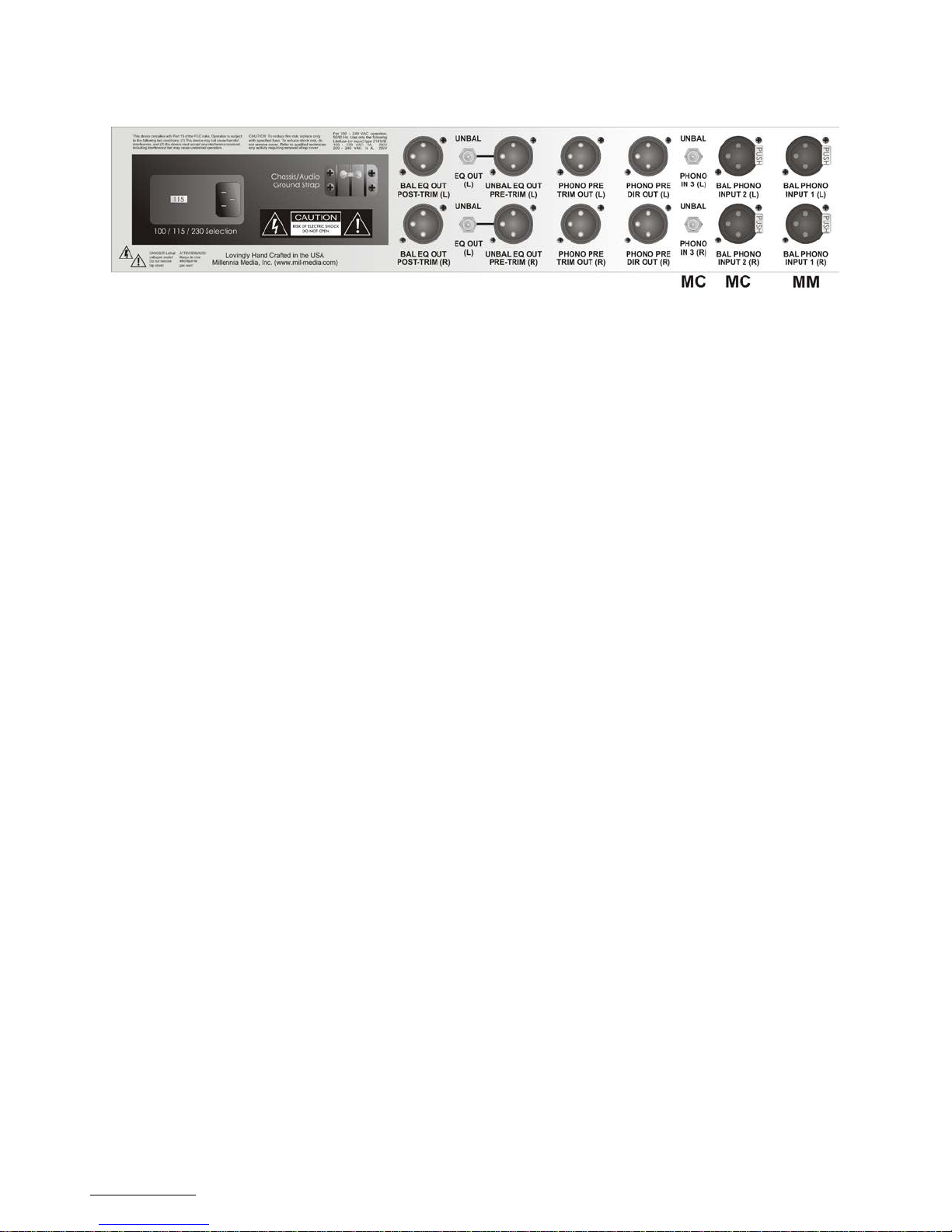
LOC REAR PANEL
(1) INPUTS:
Bal Phono Input 1 / MM Conventional 3-pin
female XLR input connectors for use with
differential-balanced phono cartridges. Can also
be used with certain line-level sources.
Standard input load resistance is 47,000 o hms.
This resistance can be changed by the user to
facilitate different pho no cartr idg e lo ad
requirements. See phono preamp PCB
illustration on page 7.
Standard input load capacitance is 470 pF. This
capacitance can be changed by the user if
necessary, but should not be lower than 270pF.
XLR pin 2 is positive polarity. XLR pin 3 is
negative polarity. Connector contacts are
Neutrik gold plated. It is suggested that XLR
cable connectors used with the LOCi employ
identical plating.
Bal Phono Input 2 /MC, Conventional 3-pin
female XLR input connectors for use with all
standard phono cartridges. Can also be used
with certain line-level sources. I nputs 2 and 3
connect to an input transformer, the Lundahl
LL9226.
Phono In 3/MC RCA input. To use the RCA input
connections, select “MC OUT” on the front panel
Use your cartridge manufactu rers recommended
R/C loading. The cartridge loading can be
modified by changing resistors and capacitors.
See illustration on page 13.
(2) PHONO PRE DIR OUT
Buffered Direct output from the pre amp card.
Post polarity and mono switching. This is the
same signal fed into the compensation and filter
circuits.
(3) PHONO PRE TRIM OUT
Adjustable, buffered signal derived from the
Direct out.
(4) UNBAL EQ OUT PRE TRIM
Post filter and compensation circuit unbal anc e d
signal. Available in both RCA and XLR
connections. Output RCA connections are
independent of input switching.
(5) BAL EQ OUT POST TRIM
Balanced output from the compensation and
filter circuits.
(6) EARTH/AUDIO GROUND JUMPER STRAP
A barrier terminal which ties earth ground to
audio ground. If ground “hum” loops are
experienced when using the LOCi, removing this
jumper may help. Using this jumper to lift
ground, the integrity of the chassis/earth safety
ground connection is never compromised.
(7) AC VOLTAGE MAINS SELECTION “100120” or “200-240”
A power entry module with a removable fuse
holder block. This fuse holder block is sele c table
for 100 - 120 Volt or 200 - 240 Volt worldwide
mains powering. The fuse block contains two
fuses - one fuse is in series with the hot power
line while the other fuse is in series with the
neutral power line. Both fuses must be installed.
To change the mains voltage selection, remove
IEC power connector and assure that the LOCi is
not connected to mains power. With a nonconductive tool, gently pry the fuse block away
from the power entry module. Remove the two
fuses and replace both with type as shown
below.
Slide out the internal PC Board, turn it over, and
reinsert the PCB so that the desired AC mains
voltage appears in the viewing window .
Double check that the fuses installed corresp o nd
to the AC mains voltage range which appears in
the viewing window. Gently push the fuse block
back until flush and snug.
FUSES:
For 100-120 VAC mains, use two 5 x 20 mm,
1A, slow blow, 250 V, Littelfuse 218 or equiv.
For 200-240 VAC mains, use two 5 x 20 mm,
1A, slow blow, 250 V, Littelfuse 218 or equiv.
Use only the power cord provided with the LOCi
unit or equivalent U/L approved type SV, SVT,
SJ, or SJT AC power s upply cord. Do not defe at
the third pin earth ground. If ground lifting is
desired, remove the Earth/Audio Ground Jum per
Strap (topic #6, above). Export units are not
supplied with a power cord
Page 5 of 16
Millennia Media, Inc.
4600 Missouri Flat Road, Suite 11
Placerville, CA 95667
http://www.mil-media.com
(530) 647-0750
Fax (530) 647-9921
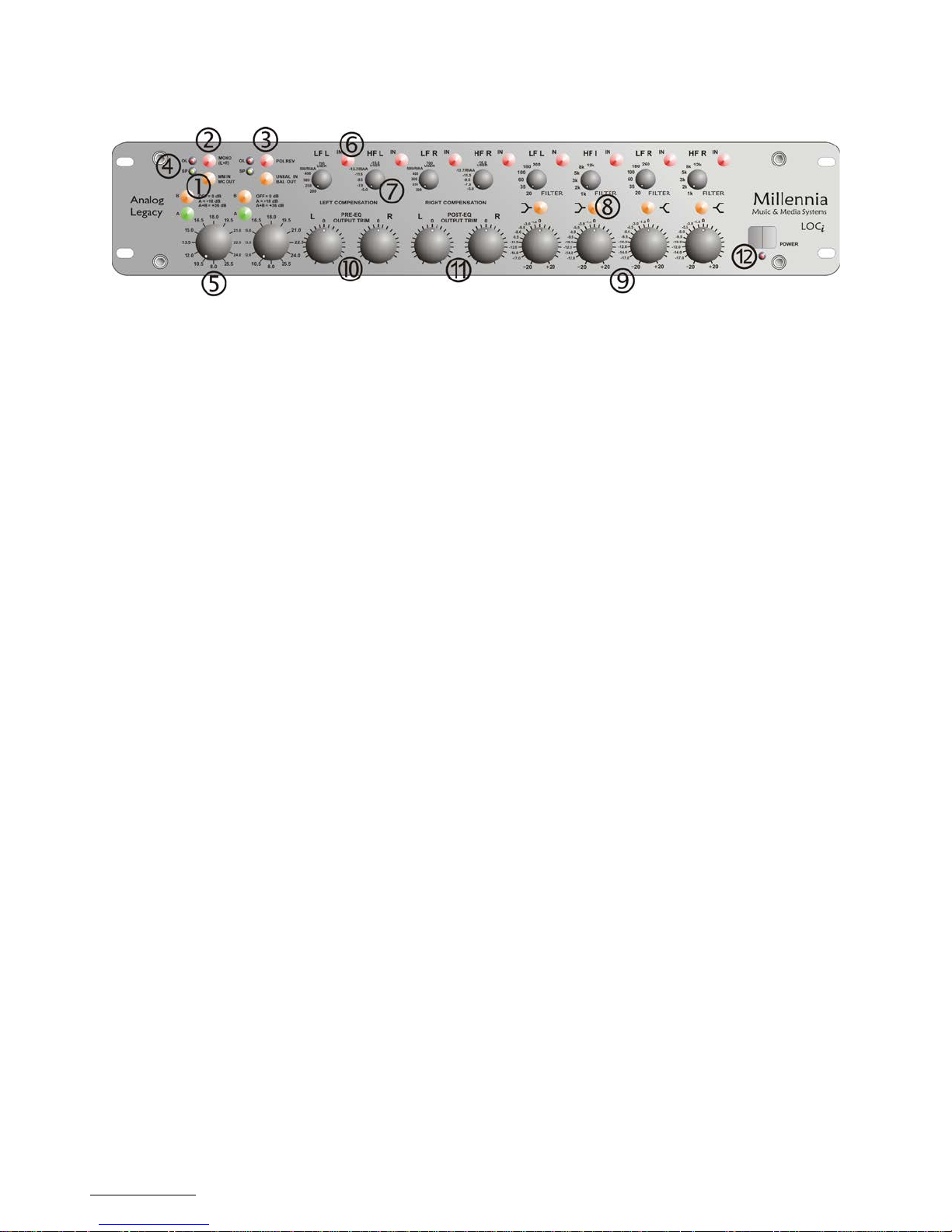
LOCi FRONT PANEL
(1) INPUT SELECT PUSHBUTTON Switches
(L&R)
Select either IN - MM (Moving Mag ne t)
connected to Input 1, or OUT MC (Moving Coil)
connected to inputs 2 or 3.
(2) MONO SELECT SWITCH "MONO (L+R)"
Pushbutton switch (German ITT) which comb ine s
left and right inputs into a summed mono signal.
When this switch is depressed and illuminated ,
left and right input signals are combined into a
single mono signal sent to both left and right
compensation and filter path inputs.
(2) POLARITY REVERSE SWITCH "POL REV"
Pushbutton switch (German ITT) which, whe n
depressed and illuminated, reverse s the pola r i ty
(180 degree inversion) of the right channel input
signal. Use with vertical groove record ings or
stereo sources which are in reversed polarity
relative to each other.
(4) SIGNAL PRESENT & OVERLOAD
INDICATORS "SP" & "OL"
Green and red LEDs (light emitting diodes)
which show signal activity (green) and high-level
(red). The green Signal Present LED illuminates
with an audio signal level of approximately -30
dBu, and should illuminate with any normal
phono input signal. The red high-level LED
illuminates with an audio signal leve l of
approximately +20 dBu at the Post EQ output
XLR jacks and should only illuminate on the very
highest peak levels.
(5) HIGH RESOLUTION PHONO GAIN
CONTROL
Detented, 36-position gain control e mploy ing a
Grayhill mil-spec gold plated rotar y switch.
Switch gain is approximately 1.5 dB per step
and is inter-channel matched to better than 0.08
dB at all settings. After a brief warm-up period,
adjustment of this switch is virtually sile nt. Tw o
illuminating pushbutton sw itches (" A" = Green
and "B" = Amber) determine the gain "range" of
the rotary switch.
When the pushbutton switches are not
depressed a nd n on-illuminated, the phono
preamplifier gain is as printed on the front panel
(9.0 dB, 10.5 dB, 12.0 dB, etc..).
When the green "A" pushbutton switch (only) is
depressed and illuminated, add 18 dB to the
gain settings as printed on the front panel.
When the green "A" and amber "B" switches are
both depressed and illuminated, add 36 dB to
the gain settings as printed on the front panel.
For example, with both pushbutton switches
depressed and the rotary switch at 1:00 o'clock
position, the preamp gain would be 55.5dB
(19.5 + 36).
(6) BAND IN/OU T S WI TC H "IN"
Pushbutton switch which places its associa te d
EQ band in circuit or out of circuit. There are
eight bands of equalization on the LOC Analog
Legacy.
Four bands provide precise phono compensation,
including RIAA and an unlimited number of
legacy curves.
Four additional bands (marked "FILT ER" ) provide
additional sculpting and repa ir tools . An EQ band
is in-circuit when its associated b and switch is
depressed and LED is illuminated. Band In/Out
switches are provided both for comparing a
single EQ band setting versus flat-band
response, and for bypassing any band entirely ,
such as with flat acoustic recordings.
(7) FREQUENCY SELECT ROTARY SWITCH
Six position rotary switch (Grayhill, g o ld
contacts, military spec) which sele c ts f ixed hig h
and low band frequency points.
LF compensation frequencies a re preset t o 2 00,
250, 300, 400, 500/RIAA, an d 700/USER (in
Hz).
HF compensation frequencies a re preset at 10
kHz to -5.0, -7.0, -9.5, -11.5, -13.7/RIAA, and -
16.0/USER (in dB).
Where a switch is marked "USER", the user may
change the value of a fixed capacitor to allow for
virtually any compensation frequenc ie s not
preset on the factory stock rotary switch points.
See printed circuit board diagram on page 8 for
capacitor socket location (C14 on LF board and
C8 on HF board).
 Loading...