

Page 1
Model
MS-510
Instruction Manual
Phone: (905) 639-0909 Fax: (905) 639-0919
E-mail: info@millenniumsignatures.com
4179-7 Harvester Road
Burlington, Ontario, Canada
L7L 5M4
Page 2
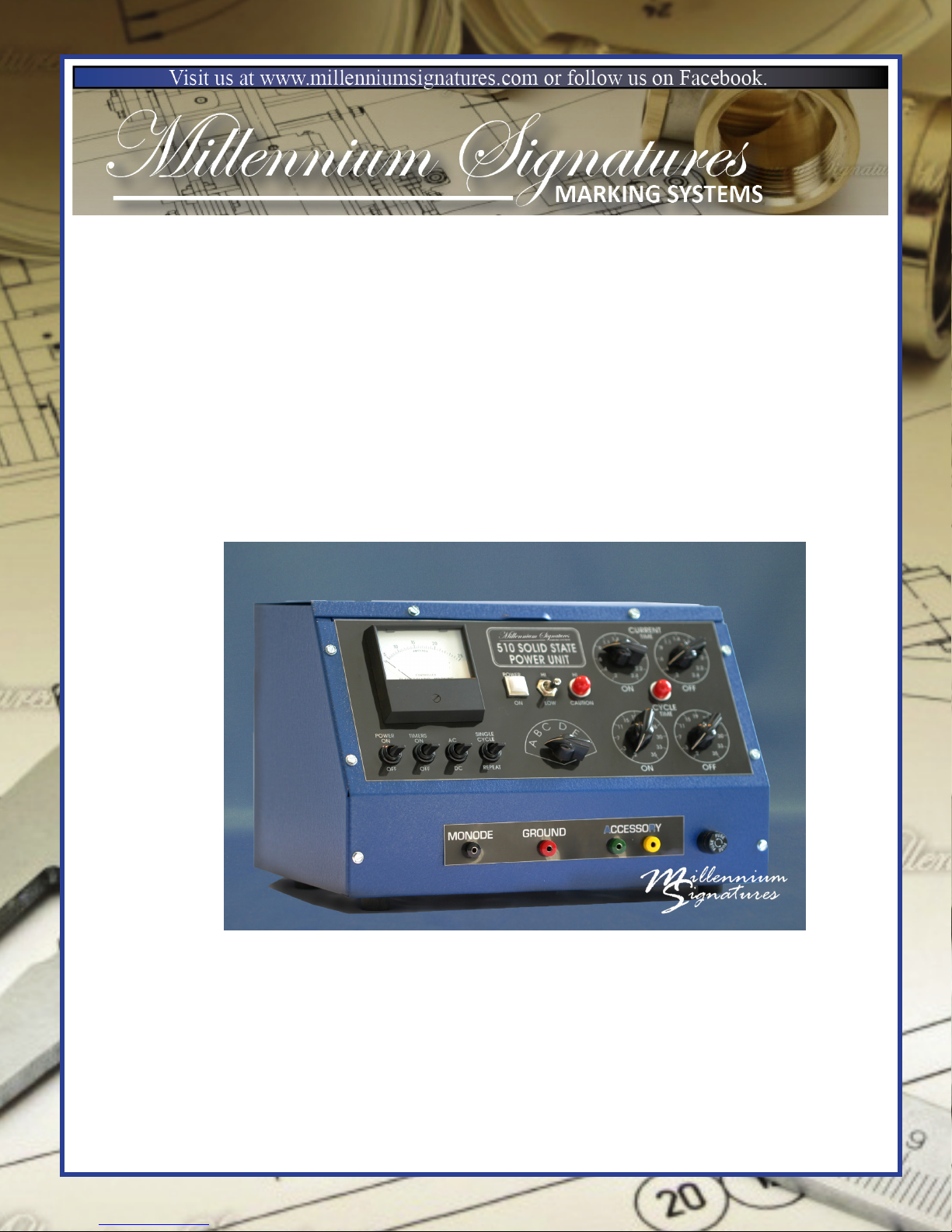
510 SOLID STATE CONTROLLED POWER UNIT
MARKING AND OPERATING PROCEDURES
You have just purchased the industry’s most durable, technically advanced electrochemical marking power unit available today. Please review the following operating
procedures to prevent damage to your unit, and to achieve good marking results.
FEATURES:
• “AC-DC” Selection
• “Low/High” Voltage Selection. Note: there are three positions on this switch.
UP=HIGH, MIDDLE=NO POWER, DOWN=LOW
• “Deep Etch” capabilities of up to .005”
• “Automatic Mode” Selection
• Two individually timed selector switches, calibrated from 0.2 to 35 seconds to
automatically control the machine cycle time
• “Power Pulse” Selection
• Two individually timed selector switches, calibrated from 0.2 to 2.4 seconds to
automatically control power pulsing
• Foot Pedal, Manual, or Automatic Operator Selection
• “High Power” indicator light
•2- “3.0” Amp Fuses for power unit protection against overloading
• Smooth action “Power Selection Switch”
• Built in alarm to alert the operator of amperage overload
• Two individual “Rotary Time Selectors”
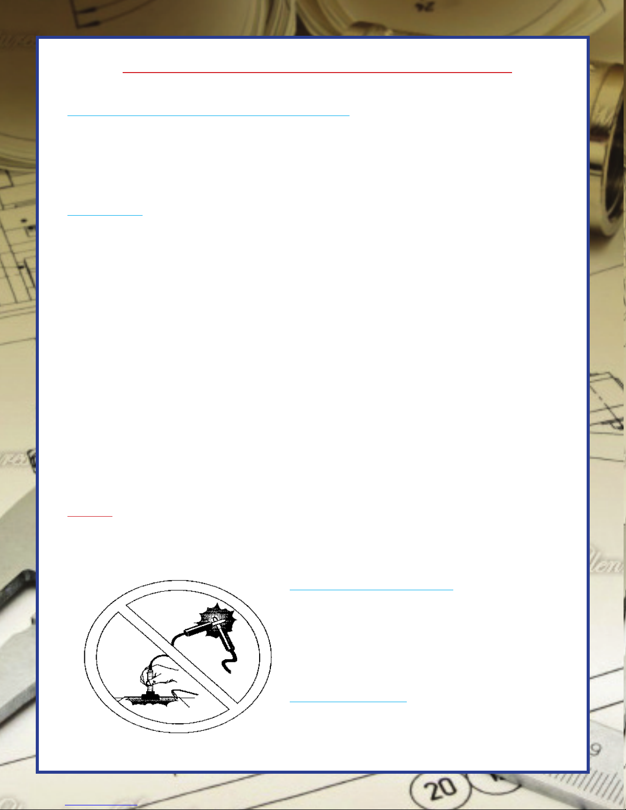
NOTE: Avoid short circuits. (See illustration 1-A) Do not cross the leads or make
contact between the marker and the grounded surface when both surfaces are bare. Your
power unit is designed to work from a 110-120 AC volt outlet only. (220 is available
upon request).
ILLUSTRATION 1-A
SET-UP AND OPERATION
The Millennium Signatures Marking Systems
510 Power Unit is designed to operate manually,
semi-automatically or automatically. Follow the
set-up and operating instructions given for your
application.
MANUAL SET-UP:
A) Plug your unit into a 110-120 AC Volt outlet
only.
Page 3
B) In the manual mode 2 wires are required. Plug
the black wire into the “monode” jack, and the red
wire into the ground jack.
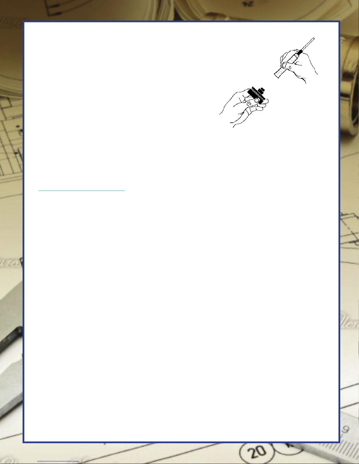
C) Attach a deep etch pad or monopad pad to the
marking head, with the “O” ring enclosed. Place
the monopad against the end of the marker (blue
side against the marker). Slide the “O” ring over the
pad and the marker until it snaps into place in the
machined groove.
D) The stencil may also be attached to the marker if
so desired, by following the procedure outlined above. ILLUSTRATION 2-A
E) If a “roll marking” technique is desired, Follow the instructions provided in the
section called “Roll Marking Applications”.
MANUAL OPERATION:
A) The four adjustment dials for cycle time and marking current time will not be
used during manual marking. Use only the following switches: “ON/OFF”, “AC-DC”,
“LOW/HIGH” and the power selection dial “A-F”. Make certain that the toggle switch
labeled “SINGLE CYCLE/REPEAT” is in the single cycle position. The toggle switch
labeled “TIMERS ON/OFF” should be in the off position unless pulsing is required.
(Refer to gures 9,11,5,4,1, & 10 respectively, Illustration 3-A.) Turn the power unit on.
Choose the proper current setting. AC produces a black mark. DC produces a white
mark and is also used for deep etching. (A white mark may be desirable for etching
various materials such as black oxide.)
B) The 510-B Power Unit is equipped with twelve power settings. With the voltage
switch (Fig. 5) set to “LOW”, the settings on the “POWER SELECTION SWITCH”
(Fig. 4) are: A=6 Volt, B=8 Volt, C=12 Volt, D=14 Volt, E=18 Volt, F=41 Volt. When
the voltage switch is set to high a red warning light is visible. Always use the lowest
power setting possible to prolong your stencil life. A good starting point is “D”.
C) Apply one of Millennium Signatures Marking Systems electrolytes to the
monopad.
D) You are now ready to mark your part. Firmly press the marker to the grounded
substrate. Contact should not exceed 2-3 seconds for a good surface etch.
E) Wipe the etched area with Millennium Signatures Marking Systems neutralizer.
Millennium Signatures neutralizers are good for both ferrous and nonferrous alloys.
RV-53 is an environmentally safe solution and is recommended.
F) After the part is dry, apply Millennium Signatures Marking Systems RPO (Rust
Protective Oil) for additional protection for your part.
Page 4

DEEP ETCHING:
To “Deep Etch” ip the toggle switch (Fig. 5) to high and select a power setting “A
thru F”. Keep in mind that the higher the power setting, the shorter the life of the
stencil. When deep etching, the best results are achieved by a series of short dwells
to minimize heat build-up. The more short dwells used the deeper the etch will be.
Always use Millennium Signatures “deep etch” pads and electrolytes for best results.
SEMI-AUTOMATIC SET-UP WITH AN AM10-A OR 30T MARKER:
A) Plug your unit into a 110V AC power outlet.
B) Connect the four wire cord set to the corresponding jacks on the power unit and the
marking machine, for example: black to black, yellow to yellow, and green to green.
The red lead is the ground. Be sure the ground lead is properly grounded to the part or
xture in semi-automatic marking operations.
Please note: On applications using marking from the bottom up or simultaneous top
and bottom marking request set-up information from your sales representative.
C) Plug the footswitch into the back of your power unit.
D) Place the appropriate monopad on the marking head and attach the insert stencil,
cap stencil, or at stencil as required.
E) Place the long tube from the #152 electrolyte pump in the open bottle of electrolyte.
Prime the pump by rotating quickly clockwise. The pump is adjusted by the small set
screw on the stop below the lever.
SEMI-AUTOMATIC OPERATION:
A) Flip the power toggle switch up to turn the unit on.
B) Choose the desired current by ipping the AC/DC (FIG. 11) toggle switch up to AC
or down to DC.
C) Choose the desired voltage. Refer to “B” in the section for “manual operation” to
review the voltage settings and operation procedure. Set to either low or high power.
(FIG. 5)
D) Set the “SINGLE CYCLE/REPEAT” switch to single cycle. (FIG. 1)
E) Adjust the “ON” dial located under the heading “CYCLE TIME” (Fig. 6). This
dial controls the amount of time the marking head remains in contact with the substrate.
Most dark marks require a setting of one to three seconds.
F) Accessory Cycle Time: Preset the accessory cycle time by rotating the dial marked
“ON” under the heading “CYCLE TIME” clockwise to the desired setting. (FIG. 6)
This will determine the amount of time the marking head spends in contact with the
substrate (swell time). The greater the number, the longer the contact will be. Once
Page 5

P
O
W
E
R
O
N
O
F
F
T
I
M
E
R
S
O
N
O
F
F
A
C
D
C
C
Y
C
L
E
C
A
U
T
I
O
N
A
B
C
D
E
F
1
.
4
1.6
1.8
2
2.2
2.4
2
4
6
.
9
1
.
1
1
.
4
1.6
1.8
2
2.2
2.4
2
4
6
.
9
1
.
1
1
9
2
1
2
0
3
0
33
35
2
1
5
1
1
3
7
2
3
7
1
1
1
5
1
9
2
1
2
0
3
0
33
35
F
U
S
E
F
U
S
E
F
U
S
E
FIG. 7
FIG. 6
FIG. 4
FIG. 5
FIG. 3
FIG. 2
FIG. 1
FIG. 12
FIG. 11
FIG. 10
FIG. 9
FIG. 8
ILLUSTRATION 3-A
set, the operator need not make any further adjustments, unless an alloy change takes
place. Set the dial marked “OFF” to determine the amount of time the head is up or
“off” the substrate. The higher the number, the longer the head is up.
G) Current Cycle Time: The current pulse is controlled by the two dials called
“MARKING CURRENT CYCLE TIME” (FIG. 7). The dials operate in the same
manner as the accessory cycle dials. They are turned clockwise. The dial marked
“ON” controls the length of time the current is delivered to the marking head. The dial
marked “OFF” controls the length of time the current ow is interrupted, even through
the marking head remains in contact with the substrate. The greater the number, the
longer the times in both cases. An amp meter (FIG. 8) has been provided for visual
conrmation of the current.
These timers are used for applications that require a long marking time. A long
marking period builds up heat that breaks down the stencil. These timers pulse the
current to the marking head. This prolongs the stencil life and reduces the total marking
time needed.
These timers are also helpful in marking contour parts. The “OFF” timer is rst to
time out. This allows time for the marking head to descend and seat the stencil on the
part before the current is applied. This improves the quality of marks on the contoured
surfaces.
H) To activate a single machine marking cycle, depress the footswitch.
Page 6

AUTOMATIC SET-UP:
Set-up for automatic marking is the same as for semi-automatic marking. Refer to the
instructions previously given.
AUTOMATIC MARKING WITH AN AM-10-A OR AM-30-T:
A) Follow steps “A through C” as outlined above for semi-automatic marking.
B) Set the “SINGLE CYCLE/REPEAT” switch to “REPEAT” to activate the automatic
mode of the power unit (FIG. 1). The AM-10-A and the AM-30-T will now cycle
automatically.
C) Set the “ACCESSORY CYCLE TIME” and the “CURRENT CYCLE TIME”. See
steps “F” and “G” above.
D) Depress the footswitch. The marking head of the AM-10-A or the AM-30-T will
descend to make contact with the substrate for the selected time. If selected, the current
will pulse on and off for the duration of the dwell time. The marking head will rise,
remain up for the selected time, and then repeat this cycle until the machine is shut off.
HOUSEKEEPING:
It is important to keep your unit free of oxidation, and salt build-up. This will ensure
years of dependable, trouble free operation.
A) Keep the cord ends, alligator plug, marking heads, and grounds clean. If corrosion
appears, use a light abrasive, such as an emery cloth, to clean it off.
B) To prevent corrosion build-up separate the marking head from the H-100 holder at
the end of each day. Remove the top plate of the B-1220 or B-2045 bench xture when
it is not in use. Following these simple steps will keep the two surfaces from fusing
together, insuring good electrical contact. This will allow quick change over for small
runs of various congurations.
C) Millennium Signatures stencils and pads are designed to be used again and again.
Simply rinse them under cold water and place them on some toweling to dry. They are
ready for use whenever you are.
Page 7

THE MILLENNIUM SIGNATURES B-1220/B-2045 BENCH
FIXTURESROLL MARKING APPLICATIONS
NOTE: To avoid short circuits (See illustration 1-A), do not cross the leads, or make
contact between the marker and the grounded surface when both surfaces are bare.
DIRECTIONS:
A) Plug the black wire into the black jack of the bench xture.
B) Remove the top plate (carbon) from the xture.
C) Pour the recommended electrolyte into the well.
E) Replace the top plate.
F) Place a deep etch pad or monopad (blue side out) on the top plate, and secure it with
the enclosed “O” ring. Make certain that the sides of th pad are tucked down inside the
well. This will insure that your pad will draw the uid without operator assistance. Use
either a B-1220-3, B-1220DE, B-2045-3, or a B-2045DE monopad for best results.
G) Place the stencil over the pad with the reading face down, as if to read the
information from the bottom of the xture. Slide the “O” ring over the stencil pad and
top plate until it snaps into the machined groove.
H) Connect the hand ground (at bottom or knife edge) to the ground jack of your
power unit.
I) Place the substrate (surface to be marked) on the stencil in front of the reading.
Place the hand ground on the substrate, and roll the substrate over the reading, using
moderate pressure.
J) Use Millennium Signatures’ neutralizer to neutralize any area of the substrate that
has come into contact with the electrolyte.
K) For added protection, apply Millennium Signatures’ Rust Preventative Oil (RPO).
It is always a good practice to apply oil to ensure rust and corrosion protection.
FOR ADDITIONAL INFORMATION CONTACT MILLENNIUM SIGNATURES
Phone: (905) 639-0909
Fax: (905) 639-0919
E-mail: info@millenniumsignatures.com
THANK YOU!
 Loading...