

MI104 INDICATOR
Weighing Indicator
User Manual

MI104 Weighing Indicator User Manual
- 2 -
CONTENTS
1. SPECIFICATIONS….………………………………………………….……......3
2. INTRODUCTION………………………………………………………………...4
3. INSTALLATION …………………………………………………………………..5
Unpacking…………………………………………………………………..5
Installation…………………………………………………………………..5
Load cell connections..………………………………………………...6
Connect Adaptor and Charging..………………………………………...6
4. DESCRIPTION……………...........……………………………………………...7
Overall view………………………………………………………………...7
Display……………………………………………………………………....7
Key board……………………………………………………………..…….8
5. OPERATION.…………………….………………………………….………….9
5.1. Power ON/OFF……………………………………………..………..9
5.2. Zero……………………........................ ............ ........ .....................9
5.3.Tare................................................................9
5.4. Sample Weighing………………………………………….………….9
5.5. Check Weighing…………………………………………….…………10
5.6. Enter to Menu………………………………….…………………….10
5.7. Set Limits…………………..............................................................10
5.8. Set check weighing mode..............................................................11
5.9. Accumulation……………………………………….………………….1 1
5.10. Accumulation automatically……………………..………………...12
5.11. Animal Weighing…………………………………………………...13
5.12. Peak Hold……………………………………………………………13
6. PARAMETER…………………………………………….…………………….13
Keys operation into menu…………………………………………….. .13
Parameter Block………………………………………………………....14
7. CALIBRATION…………………………………………………………………17
8. RS232 OUT PUT………………………………………………………………20
9. DRAWING…………………………………………………………..……………22
MI104 Weighing Indicator User Manual
- 3 -
Model
MI104
Resolution
1/30,000
Indicator housing
ABS Plastic
Stabilisation Time
1 Seconds typical
Operating Temperature
0°C ~ +40°C / 32°F - 104°F
Power supply (external)
AC Adaptor (12V/500mA) /
Ni-MH battery (1.2V/2000mAh x 6)
Calibration
External
Display
6 digits 22mm LCD display, attached backlight
Interface
RS-232 Output Optional
Zero range
0mV~5mV
Signal input range
0~15mV
ADC
Sigma delta
ADC update
Max 60 times /second
Load cell Excitation voltage
Max 5V/150mA
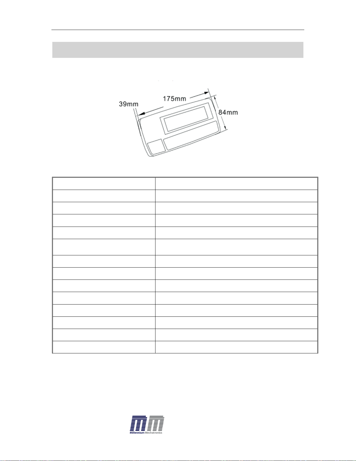
1. SPECIFICATIONS

MI104 Weighing Indicator User Manual
- 4 -
2. INTRODUCTION
The MI104 Compact weighing indicator amplifies the signals from load
cell(s), converts it to digital display as a mass/ force value.
It is suitable for general weighing or more specialized applications such as
check weighing, animal weighing and accumulation applications.
MI104 Indicator can be connected to a Serial printer or a PC.
MI104 has a large (22mm high) LCD with white LED back light display
MI104 Weighing Indicator User Manual
- 5 -
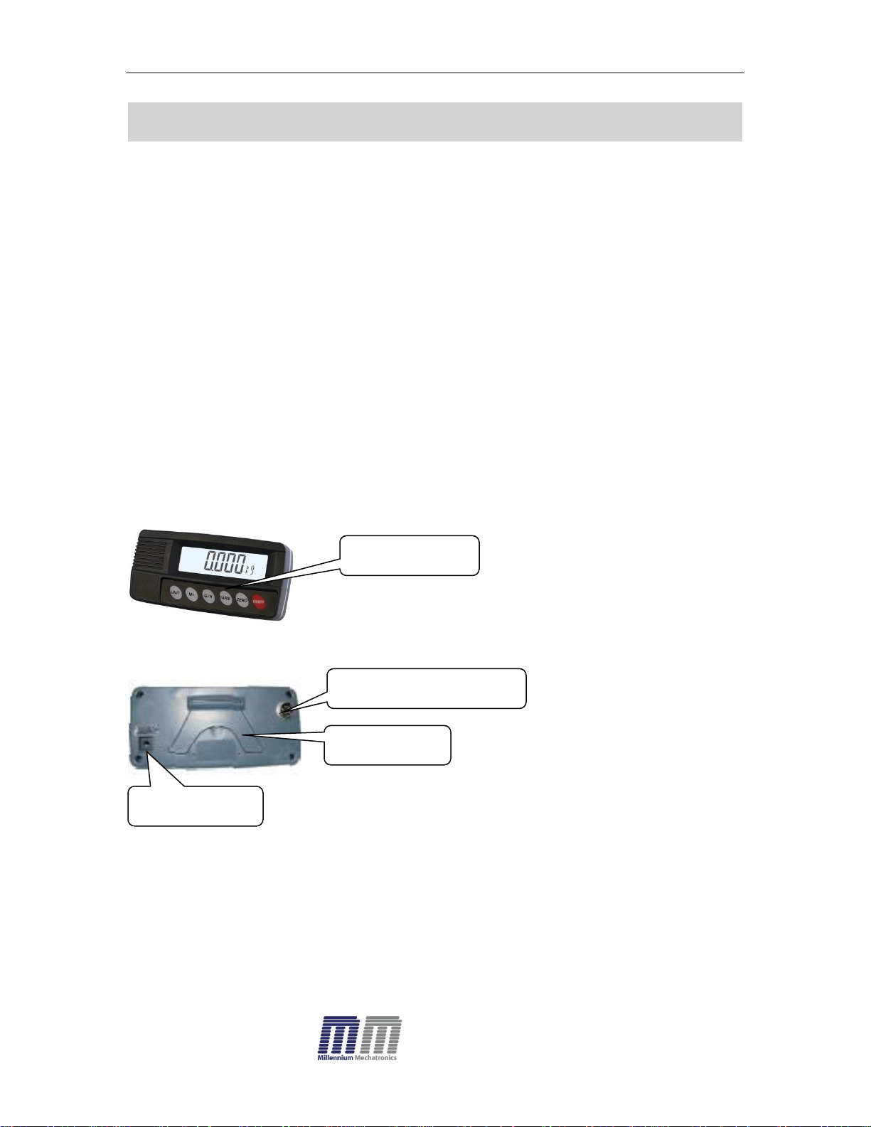
Key Board
Load cell connecter
Bracket
Adaptor jack
3. INSTALLATION
Unpacking
When you receive the indicator / scale, inspect it to make sure that it is not
damaged and that all are parts are included:
Remove the Indicator from the carton.
Remove the protective covering. Store the packaging to use if you need
to transport the indicator later.
Inspect the indicator for damage.
Make sure all components are included.
1. Indicator
2. Adaptor
3. Manual
4. Load cell Output connecter -5 pin
5. RS-232 Output Connecter- 9 pin
Installation
Place the Indicator on a table.
Connect the load cell cable in to the indicator load cell connecter. Load
cell connecter (5 pin)is located on the back side of the indicator.
Connect the adaptor pin in to the indicator adaptor jack.
Adaptor jack is located on the back side of the indicator.
Connect the power Adaptor to your AC power socket.
MI104 Weighing Indicator User Manual
- 6 -
5Pin Connection
Pin 1
Signal +
Pin 2
Signal -
Pin 3
Shield
Pin 4
Exc -
Pin 5
Exc +
Turn on the On/Off key. If you want to turn off, press the key again.
Display will show the software version number and will start self-checking.
After self-checking, display will come to normal weighing mode.
Warm-up time of 15 minutes is recommended for stabilization after
switching on.
Calibrate with accurate calibration weights, minimum 1/3 of the scale
capacity is recommended for calibration.
For calibration see details in Section 6- Parameter.
Load cell connections
Connect load cell cables to the terminal as shown below.
MI104 can connect upto four 350 ohm load cells/ eight 700 ohm load cells.
The load cell excitation voltage is 5V DC ±5% between Excitation + and
Excitation -.
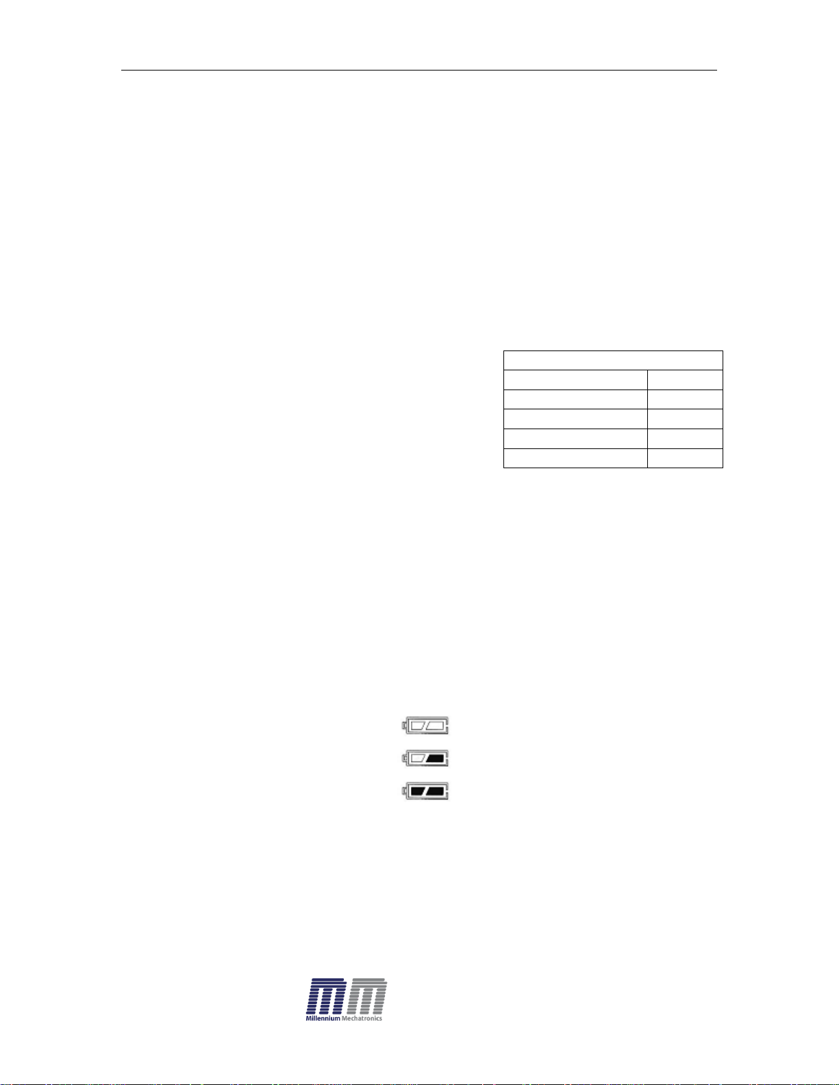
Connect Adaptor and Charging
To charge the battery insert the power adaptor pin to jack. Plug the Adaptor
into the mains power. The indicator does not need to be turned on.
The battery should be charged 6 hours for full capacity.
The symbol status of the battery
Battery voltage is very low
Low voltage
Fully charged
.
Do not use any other type of power adaptor , except the one supplied with
the scale.
Verify that the AC power socket outlet is properly protected.
Note: Please charge the battery fully before using the scale for the first
time.
MI104 Weighing Indicator User Manual
- 7 -
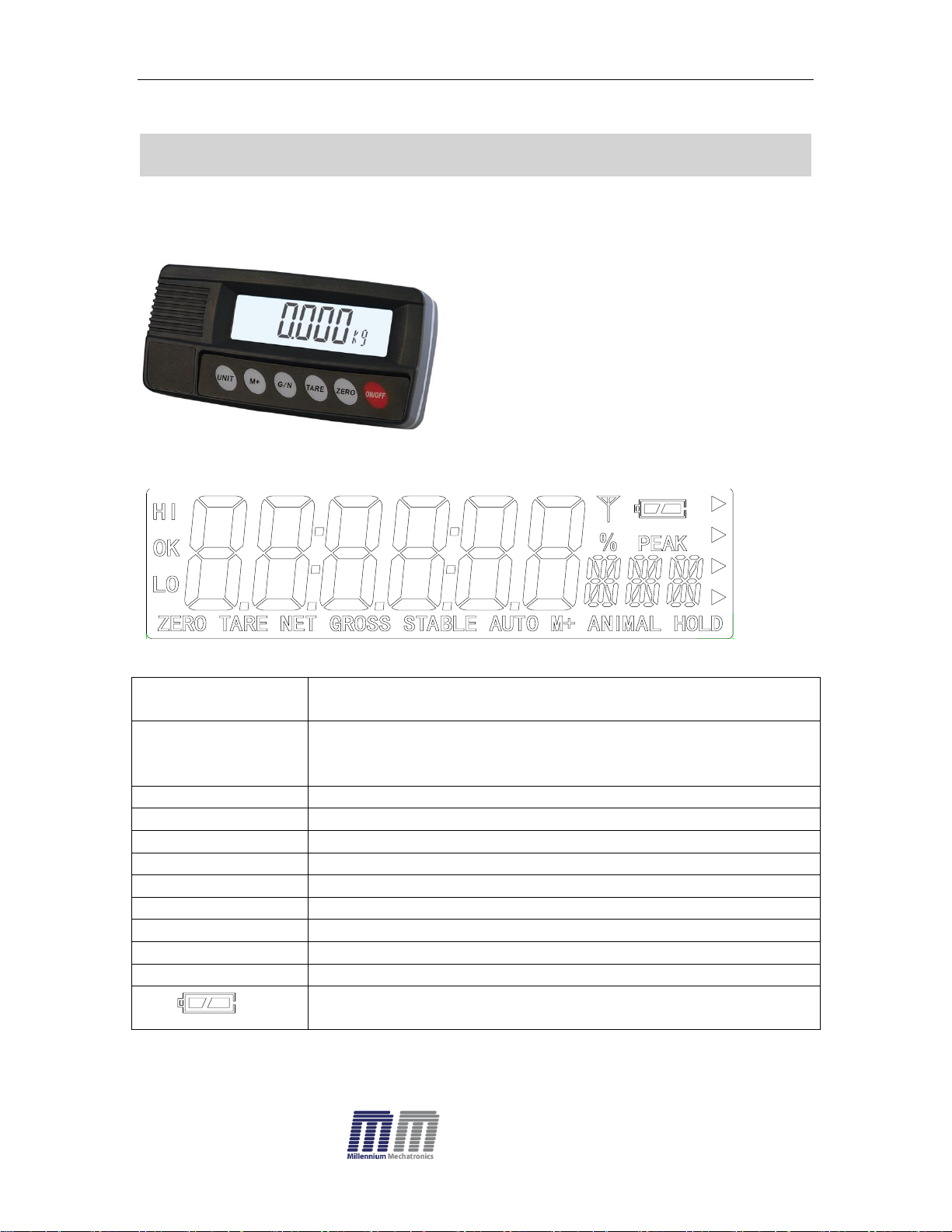
DISPLAY
FUNCTION
HI
OK
LOW
Check weighing
ZERO
Indicator for Zero display
TARE
Indicator for Tare display
GROSS
Indicator for Gross weight
NET
Indicator for Net weight
STABLE
Indicator for Display stability
AUTO
Indicator for Auto Accumulation
M+
Indicator for Accumulation
ANIMAL
Indicator for Animal Weighing Mode
HOLD
Indicator for Hold/ Lock
Indicator for Charging status of battery.
FROUNT
BACK
4. DESCRIPTION
Overall View
Display

- 8 -
Key Board
KEY
FUNCTION
Turn the power On/ Off
Used to reset to Zero. In setting mode can use to confirm entry
Used to record tare values and change the value from gross
value to net value. In setting mode, this key can be used to
increase the value and scroll (up) in menu.
When the scale has been tared and display is in gross or net
mode. When using the settings mode, can be used to move
active digits to the right.
For print the results, to the PC or printer using the optional RS232 interface. It also adds the value to the accumulation
memory if the accumulation function is not automatic. When
using the settings mode, this key can be used to move active
digits left.
Switch to unit of weight(kg/lb/oz). In setting mode, escape back
to menu/ weighing mode.
MI104 Weighing Indicator User Manual

MI104 Weighing Indicator User Manual
- 9 -
5. OPERATION
Initial Start – Up:
Warm-up time of 15 minutes stabilizes the measured values after switching on.
5.1. Power ON/OFF:
Switch on the balance by pressing key.
The display is switched on after the self test(countdown). To switch off,
press again the key.
5.2. Zero
You can set the display to zero any time by pressing key.
5.3 . Tare
The weight of any container can be tared by pressing button so that
with subsequent weighing , the net weight of the object being weighed is
displayed.
Load weight on the platform.
Press key. Zero is displayed, and tare is subtracted.
Remove weight on the platform. Tared weight is displayed. It can set only
one tare value. It can display with a minus value.
Press G/N to change between gross weight and net weight.
To clear the tare value, remove the load and press key. Zero is
displayed, tare weight is cleared.
5.4. Weighing
Place goods to be weighed on the platform.
Wait few seconds for “STABLE” to appear on display.
Read the display.
Avoid overloading. When display appears “ol” reduce the load or
unload.

MI104 Weighing Indicator User Manual
- 10 -
Set hi
F0 H-L
Set Lo
5.5. Check Weighing
It can set an upper or lower limit when weighing with the limits range.
The unit will indicate whether a display value(weight) is within upper or lower
limits with an alarm sound . For details see the parameter F3 oFF.
Check mode 1: No beep sound when within the limits. Function turned
off.
Check mode 2: When the weight is between the limits. OK will shown and
beeper will be sound.
Check mode 3: When the weight is out of the limits, the beeper will
sound and OK will shown.
5.6. Enter to Menu
In the weighing mode, press and together.
Display will be appear
5.7. Set limits
Press to enter the function.
Press key to select the limit.
Display will appear or
Press key to enter, press key to move active digits.
Press to change the value. After enter the value press to sure.
Press to escape.
5.8. Set check weighing mode.

MI104 Weighing Indicator User Manual
- 11 -
bP 1
bP 3
bP 2
ACC 1
bEEP
F3 oFF
After entering the settings mode,
Press until display will be appear
Press key to enter, press until display show
Press key to enter, press
Check mode 1
Check mode 2
Check mode 3
Select desired setting by pressing and press key to confirm, press
to escape.
Note: The load weight must greater than 20 scale divisions for the check
weighing operations.
To disable the check weighing function, enter zero into both limits.
5.9. Accumulation
Accumulation
Place the goods on the platform to be weigh
Wait few seconds for display stable, then press . The value will be
saved and printed (if the printer is connected).
Display will be appear this display will
appear two seconds only.
Remove the load and wait few seconds for display return to zero.
Place the second goods on the platform.

MI104 Weighing Indicator User Manual
- 12 -
ACC 2
ACC 0
Wait few seconds for display stable. Then press . The value will be
saved.
Followed by the total number of weight will be displayed
It can continue the process until the maximum capacity or value.
Note: When you change the weighing unit this saved values will be clear.
Accumulated Total
Manually, the scale can be set to accumulation by pressing , when an
optional printer is connected. See details in F4 Prt.
Memory Recall
When display shows Zero, you can see the number of weighing and total
weight by pressing , display will be shown for two seconds.
Delete the Memory
When display of Zero, you can see the number of weighing and total
weight by pressing , display will be shown for two seconds. Press
during this display. The memory data are deleted and display will
be shown
5.10. Accumulation Automatically
In this function the individual weighing values are automatically added
into the memory. There is no need to press any keys.
For this function, set to parameter F4 Prt and select P AutO.
After select this function, display indicator AUTO will be shown.
Place the goods on the platform to be weighed
After the display is stable, the beep will sound twice.

MI104 Weighing Indicator User Manual
- 13 -
Unload the goods, the weighing value will be saved automatically and will
be follow beep sound once.
It can continue the process until the maximum capacity or value.
5.11. Animal Weighing
MI104 can use for moving (fluctuating) loads.
For this function, set to parameter P4 CHk to ModE 2
After select this function, display indicator ANIMAL will be shown.
Bring the load / animal on to the platform.
When the display gets stable for few seconds , the reading will be locked
followed by a beep.
5.12. Peak Hold
MI104 can operate peak hold function, peak reading will be stored and will
update automatically when a newer peak is reached.
For this function, select parameter P4 CHk to ModE 4
In the normal weighing mode press and keys together to turn
on or turn off Peak hold operations.
To cancel the peak reading from Hold, press Zero key for 2 seconds.
6. PARAMETERS
KEYS OPERATIONS INTO THE MENU
Enter the menu
In weighing mode, press key and key together.

MI104 Weighing Indicator User Manual
- 14 -
Menu
Sub-Menu
Description
F0 H-L
Weighing with
set limits
SET Lo
Lower limit value
SET Hi
Upper limit value.
F1 toL
to CLr
Clear the accumulation memory with out
printout
to P-C
Print the total accumulation memory and clear
the total memory
to Prt
Print the total accumulation and keep all the
memory.
F2 Unt
G
Weighing units
Lb
Oz
Tj
th
Select the menu
Press , it can change the menu block one by one.
Using increase the digit.
Enter the selected menu
Press , it can confirm, which will be shown displayed.
Change the digit
Press , it can change the active digit.
Return to weighing mode
Press , exit from the menu.
PARAMETER BLOCK

- 15 -
F3 oFF
Bl
El on
Display of back light on
El au
Display of back light on
automatically
El off
Display of back light off
beep
Bp 1
Beep sound off during the
check weighing
Bp 2
Beeper will be sounded with in
the check weighing limits
Bp 3
Beeper will be sounded above
the check weighing limits
F4 prt
RS 232 mode
P prt
By pressing , weighing value will be
added to the memory and print the print out
P cont
Send data continuously
Seire
Also send data continuously
Ask
Bi- direction , through PC
Commands R= Send, T= Tare, Z= Zero
P cnt 2
No documented
P stab
Send data of stable weighing values
P auto
Automatic accumulation.
Individual weighing values are automatically
added
Set BAUD rate
After setting the RS 232 mode, display will be shown current
baud rate b XXX. Avail able baud rate: b600, b1200,
b2400, b4800 and b9600 If necessary change the baud
rate by pressing and enter by pressing
Set print out format
If enter settings p prt, p auto, p cont and connected
optional printer
Pr X
Print format
Only for p prt, p
auto format
Lab X
Print format
Cont 1
Only for p cont only
N.A
Cont 2
Cont 3
Set printer type
Ty-tp
Ticket printer
MI104 Weighing Indicator User Manual

MI104 Weighing Indicator User Manual
- 16 -
Ty 711
Label printer
Lp 50
Label printer
prog
pin
Enter the programming and calibration menus
by using password (Refer section 7 –
Calibration on password entry).
Menu
Sub Menu
Description
P1 ref
A2n 0
0.5d
Auto zero point settings
1d
2d
4d
0 – auto
P1 0
Zero setting range.
When the display is turn on the scale is set to
zero
P1 2
P1 5
P1 10
P1 20
0 – range
P 2 0
Manually zero setting range, by pressing
P 2 2
P 2 5
P 2 10
P 2 20
Speed
S 7.5
S 15
S 30
S 60
P2 cal>
SigRa>
dECi
C 0
Decimal point settings
C 0.0
C 0.00
C 0.000
C0.0000
inC
1
Increment settings
2 5 10
20
50
CAP
00000
Enter the scale capacity
CAL
Linear
Linear calibration
nonlin
Normal calibration
P3 pro
Tri
The display will show XXXXX. For trimming the load cells,
PROGRAM PARAMETERS

MI104 Weighing Indicator User Manual
- 17 -
You can calculate new rate by this formula & enter it:
New rate = Old rate*Display weight/ Calibration weight.
Count
This display will show XXXXX for indicating the internal
counts.
Reset
Factory default settings
gra
Set the local gravity
P4 chk
Mode 1
Normal weighing mode. (check weighing, accumulation)
Mode 2
Animal weighing mode. (scale can lock reading, when little
unstable)
Mode 3
This is a subtraction scale (print out “-“ weight)
Mode 4
Peak Hold mode. (Scale can hold maximum reading)
prog
Fo h-l
pin
P1 ref
P 2 cal
dec
cal
7. CALIBRATION
In weighing mode, press key and key together.
Press repeatedly until display shows.
Press , display will show.
Enter the password. Press , and
Display will show
Press , display will show.
Enter the function by pressing twice , display will show
Press repeatedly until display shows.

MI104 Weighing Indicator User Manual
- 18 -
linear
Nonlin
Nonlin
unload
06.000
load
pass
Enter the function by pressing , display will show
Press to select for normal calibration
Normal Calibration:
Enter the function by pressing , display will show
Make sure there are no loads on the platform and wait few seconds for
stable indicator on.
Enter the function by pressing , display will show
Value of last weight used for calibration
Change this number to the weight being used for calibration now, by using the
keys , ,
Enter the selected setting by pressing ,
display will show.
Load the calibration weight on the scale (or load cell) and wait
few seconds for display stability.
After the STABLE indicator is on, press , display will
show.

MI104 Weighing Indicator User Manual
- 19 -
linear
linear
Load 0
Load 1
Load 2
Load 3
pass
After the calibration , the display will start a self test. Remove the load from scale
during the self test. Display will come to weighing mode automatically.
If display shows error or incorrect value, repeat the procedure again.
Linear Calibration
The linearity error caused by the performance of the weighing unit can be
corrected by “Linearity Calibration”. The digital linearization function can reduce
the linearity error. MI104 employs a 3-point linearisation.
Precise weight (1/3rd, 2/3rd and full capacity ) are needed for Linear
calibration.
Enter the function by pressing , display will be shown
Make sure there are no loads on the platform and wait few seconds for
STABLE display on.
Enter the function by pressing , display will be shown
Load the first calibration mass weight on the platform (mass weight should
be1/3 of the max capacity) and wait few seconds for STABLE display .
Then press , display will be shown
Load the second calibration mass weight on the platform (mass weight
should be2/3 of the max capacity) and wait few seconds for STABLE
display .
Then press ,display will be shown
Load the third calibration mass weight on the platform (mass weight should
be the max capacity) and wait few seconds for STABLE display .
Then press ,display will be shown

MI104 Weighing Indicator User Manual
- 20 -
Pin 2
RXD
Input
Receiving data
Pin 3
TXD
Output
Transmission data
Pin 5
GND ― Signal ground
,
-/
k g CR
LF
WEIGHT UNIT
TERMINATOR
After the calibration the display will start a self test. Remove the load from
platform during the self test. Display will come to weighing mode automatically.
If display shows any error or incorrect value, repeat the procedure again.
8. RS-232 OUTPUT
MI104 Indicator can send data through RS 232 output.
Specifications:
RS-232 output of weighing data
Code : ASCII
Data bits : 8 data bits
Parity : No Parity
Baud rate : 600bps to 9600bps selectable
RS-232 (9pin Round connector suppled with MI104)
9pin Round Connector (MI104) and 9 pin DB9 Connecter for PC/Printer:
Indicator (9 Pin Round) Computer / Printer (DB9)
Pin 2: Pin 3
Pin 3: Pin 2
Pin 5: Pin 5
Note: If data not getting in to PC, inter-change the Pin 2 and Pin 3 connections from
one of the connecter. (9 pin round connector is supplied with MI104 Indicator.)
Continuously output protocol
Weighing Mode;
-14-
HEADER1 HEADER2 WEIGHT DATA
HEADER1: ST=STABLE, US=UNSTABLE
HEADER2: NT=NET, GS=GROSS

MI104 Weighing Indicator User Manual
- 21 -
Lab
Pr
0 1 2
3
0
2011/12/30 11:11
WEIGHT: 1.00kg
WEIGHT: 1.00kg
1
2011/12/30 11:11
WEIGHT: 1.00kg
TOTAL: 1.00kg
WEIGHT: 1.00kg
TOTAL: 1.00kg
2
2011/12/30 11:11
NET: 1.00kg
GROSS: 1.00kg
TARE: 0.00kg
NET: 1.00kg
GROSS: 1.00kg
TARE: 0.00kg
3
2011/12/30 11:11
NET: 1.00kg
GROSS: 1.00kg
TARE: 0.00kg
TOTAL: 10.00kg
NET: 1.00kg
GROSS: 1.00kg
TARE: 0.00kg
TOTAL: 10.00kg
4
2011/12/30 11:11
S/NO: 10
WEIGHT: 1.00kg
S/NO: 10
WEIGHT: 1.00kg
5
2011/12/30 11:11
S/NO: 10
WEIGHT: 1.00kg
TOTAL: 10.00kg
S/NO: 10
WEIGHT: 1.00kg
TOTAL: 10.00kg
6
2011/12/30 11:11
S/NO: 10
NET: 1.00kg
GROSS: 1.00kg
TARE: 0.00kg
S/NO: 10
NET: 1.00kg
GROSS: 1.00kg
TARE: 0.00kg
7
2011/12/30 11:11
S/NO: 10
NET: 1.00kg
GROSS: 1.00kg
TARE: 0.00kg
TOTAL: 10.00kg
S/NO: 10
NET: 1.00kg
GROSS: 1.00kg
TARE: 0.00kg
TOTAL: 10.00kg
Print Out Formats
Note: Lab 0 & 2 for English , Lab 1 and 3 are optional.

MI104 Weighing Indicator User Manual
- 22 -
No
Parts Name
1
Key board overlay
2
Overlay
3
Upper cover
4
Display protection Plate
5
Key pad hat
6
Main board PCBA
7
Insulated washer
8
Seal thread screw
9
Rubber sealing ring
10
Self-thread screw
11
Battery Clamp
12
Ni- NH battery
13
Washer
14
5 pin air connector
15
Bottom cover
16
Name plate
17
Self-thread screw
18
Adaptor jack
19
Bracket
9. DRAWING
 Loading...