

Page 1
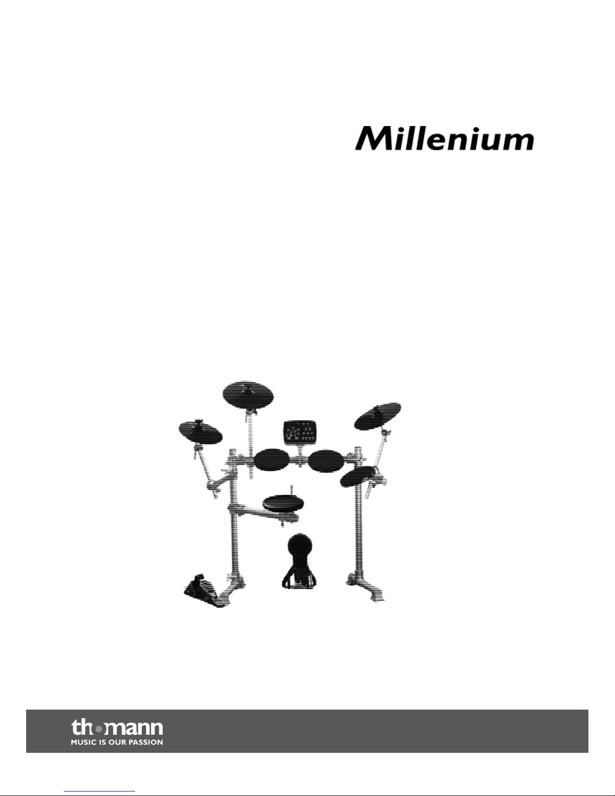
MPS-250 USB
e-drum set
user manual
Page 2

Musikhaus Thomann e.K.
Treppendorf 30
96138 Burgebrach
Deutschland
Telephone: +49 (0) 9546 9223-0
E-mail: [email protected]
Internet: www.thomann.de
05.02.2014, ID: 307340 (V2)
Page 3

Table of contents
1 General notes............................................................................................................................ 4
2 Safety notes............................................................................................................................... 5
3 Features....................................................................................................................................... 7
4 Scope of delivery..................................................................................................................... 8
5 Assembly..................................................................................................................................... 9
6 Installation.............................................................................................................................. 13
7 Connections and controls................................................................................................ 15
8 Operation................................................................................................................................. 18
8.1 Functions......................................................................................................................... 18
8.2 Playing the pads............................................................................................................ 21
9 Technical data........................................................................................................................ 23
10 Connector and pin assignments................................................................................... 24
11 Appendix.................................................................................................................................. 25
11.1 Kit list............................................................................................................................... 25
11.2 Voice list......................................................................................................................... 25
11.3 MIDI implementation................................................................................................ 29
12 Cleaning.................................................................................................................................... 30
13 Protecting the environment........................................................................................... 31
Table of contents
MPS-250 USB
3
Page 4
1 General notes
This user manual contains important information on safe operation of the device.
Read and follow all safety notes and all instructions. Save this manual for future refer‐
ence. Make sure that it is available to all persons using this device. If you sell the
device, include the manual for the next owner.
Our products are subject to a process of continuous development. We therefore
reserve the right to make changes without notice.
This section provides an overview of the symbols and signal words used in this user
manual.
Signal word Meaning
DANGER! This combination of symbol and signal
word indicates an immediate dangerous
situation that will result in death or
serious injury if it is not avoided.
CAUTION! This combination of symbol and signal
word indicates a possible dangerous sit‐
uation that can result in minor injury if it
is not avoided.
NOTICE! This combination of symbol and signal
word indicates a possible dangerous sit‐
uation that can result in material and
environmental damage if it is not
avoided.
Warning signs Type of danger
Warning – danger zone.
Symbols and signal words
General notes
e-drum set
4
Page 5
2 Safety notes
Drum modules are intended to be used for converting digital trigger signals from
drum pads to various percussion sounds. Use the unit only as described in this
manual. Any other use or use under other operating conditions is considered to be
improper and may result in personal injury or property damage. No liability will be
assumed for damages resulting from improper use.
This device may be used only by persons with sufficient physical, sensorial, and intel‐
lectual abilities and having corresponding knowledge and experience. Other persons
may use this device only if they are supervised or instructed by a person who is
responsible for their safety.
DANGER!
Danger for children
Ensure that plastic bags, packaging, etc. are disposed of properly and
are not within reach of babies and young children. Choking hazard!
Ensure that children do not detach any small parts (e.g. knobs or the
like) from the unit. They could swallow the pieces and choke!
Never let children unattended use electrical devices.
CAUTION!
Possible hearing damage
With loudspeakers or headphones connected, the device can produce
volume levels that may cause temporary or permanent hearing impair‐
ment.
Do not operate the device permanently at a high volume level.
Decrease the volume level immediately if you experience ringing in
your ears or hearing impairment.
NOTICE!
Operating conditions
This device has been designed for indoor use only. To prevent damage,
never expose the device to any liquid or moisture. Avoid direct sunlight,
heavy dirt, and strong vibrations.
Intended use
Safety
Safety notes
MPS-250 USB
5
Page 6

NOTICE!
External power supply
The device is powered by an external power supply. Before connecting
the external power supply, ensure that the input voltage (AC outlet)
matches the voltage rating of the device and that the AC outlet is pro‐
tected by a residual current circuit breaker. Failure to do so could result
in damage to the device and possibly the user.
Unplug the external power supply before electrical storms occur and
when the device is unused for long periods of time to reduce the risk of
electric shock or fire.
Safety notes
e-drum set
6
Page 7

3 Features
n 184 sounds
n 20 pre-programmed drum kits
n 50 pre-programmed patterns
n Metronome
n Recording and playback function
n Flexible pad programming
n Connections: Headphones, Line IN/OUT and USB-MIDI
n Automatic switchoff
Features
MPS-250 USB
7
Page 8
4 Scope of delivery
Before assembling the e-drum set, verify that the delivery is complete by
means of the list below.
n Rack, consisting of two side legs, a horizontal crossbar and three wing arms with
holder clamps (pre-assembled unit)
n 2 × supports for crash pad and ride pad
n 1 × support for hi-hat pad
n 2 × feet with pre-mounted holder clamps
n 3 × tom pads, 8"
n 1 × tom pad with rim trigger, 8"
n 1 × crash pad with choke function, 12"
n 1 × ride pad, 12"
n 1 × hi-hat pedal and hi-hat pad, 8"
n 1 × bass drum pad, 6"
n Drum module
n Complete pad cabling
n 9 V
(DC) power supply unit
Scope of delivery
e-drum set
8
Page 9
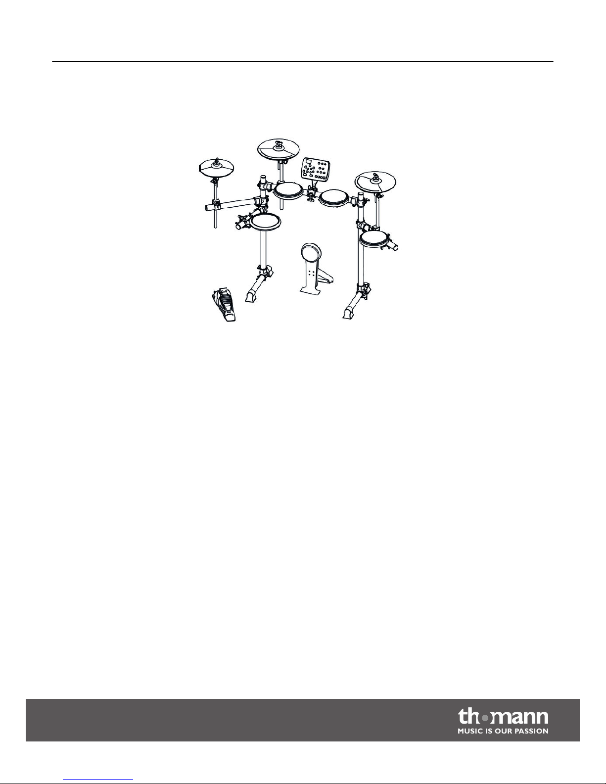
5 Assembly
The following overview shows the typical setup of a drum set.Overview
Assembly
MPS-250 USB
9
Page 10
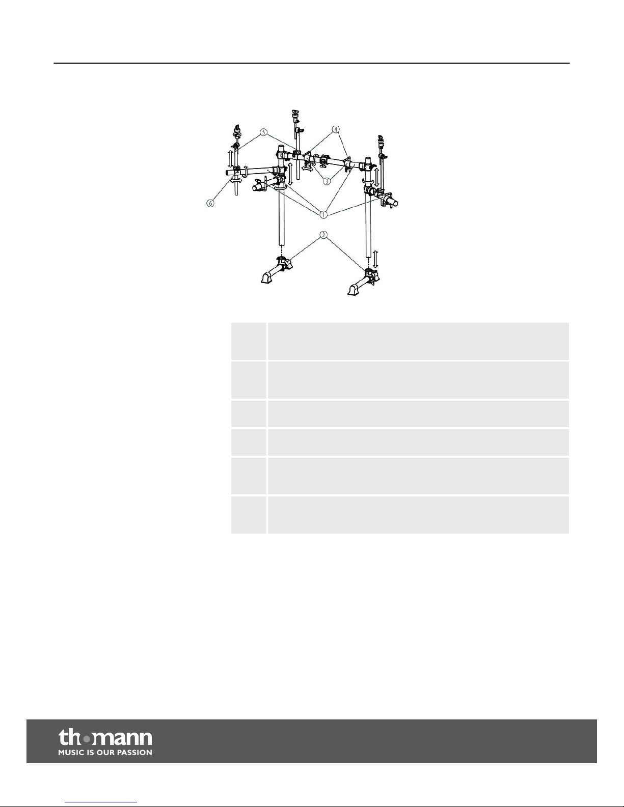
1 Adjust the height of the rack’s horizontal crossbar and three wing arms
according to your preferred playing position. Then tighten the retaining
screws.
2 Position the two feet on the floor and insert the two rack legs into the
holder clamps provided for this purpose. Make sure that the lower ends of
the legs are resting flush on the floor. Then tighten the retaining screws.
3 Position the holder clamps for the individual pads. Then tighten the
retaining screws.
4 Turn the L-rods into a suitable position for mounting the pads. Then
tighten the retaining screws.
5 Insert the crash pad, ride pad and hi-hat pad supports into the respective
holder clamps on the rack. Secure the supports at the desired vertical
position using the retaining screws.
6 Loosen the retaining screws at the support joints and orient the supports
so as to match your preferred playing position. Then re-tighten the
retaining screws.
Setting up the rack
Assembly
e-drum set
10
Page 11
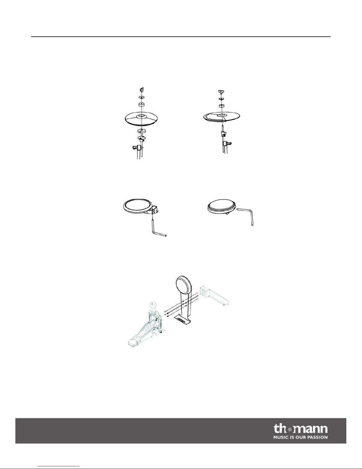
Unscrew the wing nuts from the pad supports and remove the felt washers from the
supports. Place the pads on their supports as illustrated. Put the felt washers on top
of the pads, and secure the pads on their supports using the respective wing nuts.
Observe the part designations of the pads during assembly (HI-HAT = A-8 Hi-Hat,
CRASH = A-12 Cymbal edg., RIDE = A-12 Cymbal).
Fit the snare pad (left) and the tom pads (right) onto the L-rods as illustrated, align
the L-rods according to your preferred playing position, and tighten the retaining
screws on the rack and on the pads.
The bass drum pad is played with a bass drum pedal (not included in the scope of
delivery). The following figure shows an example of assembling the bass drum pad
with a bass drum pedal. Observe the assembly instructions of the bass drum pedal.
Hi-hat, crash, ride
Snare, toms
Bass drum
Assembly
MPS-250 USB
11
Page 12

Attach the drum module to its support using the screws supplied, as illustrated. Then
affix the support plate to the holder clamp on the rack.
Finally adjust the rack and all pads according to your preferences. As a final step, all
pads must be connected to the drum module by means of cables (see Ä ‘Connecting
the pads’ on page 13).
Drum module
Setup and cabling
Assembly
e-drum set
12
Page 13
6 Installation
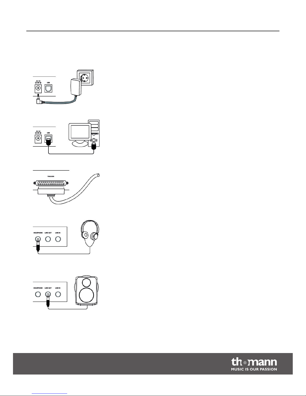
Connect the power supply unit included in delivery to the DC 9V input on the rear of
the drum module and then insert the power plug into the socket outlet.
Connect an external USB device (PC) to the USB port on the rear of the drum module.
Connect the pads on the rack to the D-sub connector on the rear of the drum module
using the cable harness (pad cable) supplied (observe cable markings).
Connect your stereo headphones to the HEADPHONE output on the rear of the drum
module.
Connect an active speaker, an amplifier or your PA system to the LINE OUT output on
the rear of the drum module. When connecting an external mono system, we recom‐
mend using a stereo-to-mono adapter.
Connecting the power supply
Connecting USB devices
Connecting the pads
Connecting headphones
Connecting a speaker, amplifier or PA
system
Installation
MPS-250 USB
13
Page 14
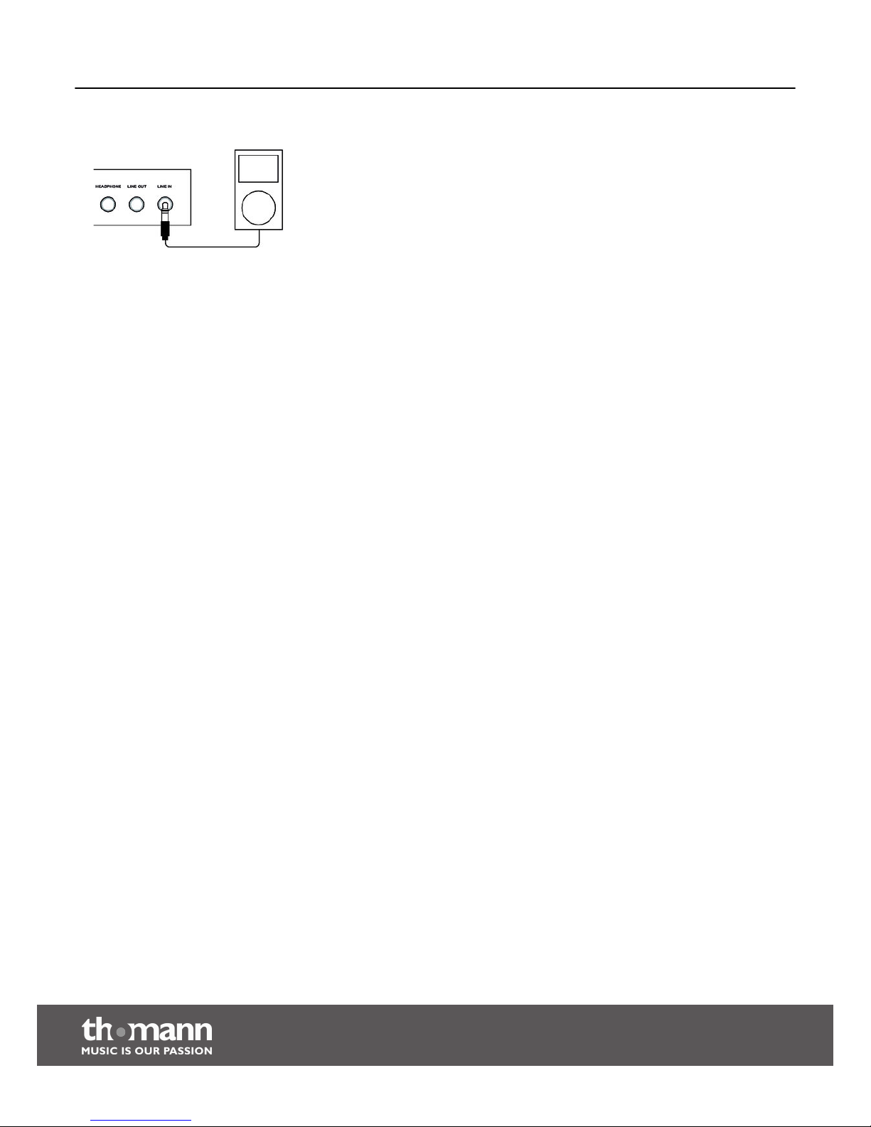
Connect audio devices such as CD players, MP3 players, etc. to the LINE IN input on
the rear of the drum module.
Connecting audio devices
Installation
e-drum set
14
Page 15
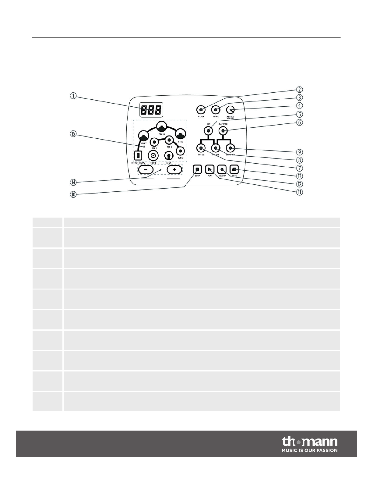
7 Connections and controls
1 7-segment LED display, 3 digits
2 [CLICK]
Button for switching the metronome on/off.
3 [TEMPO]
Button for setting the metronome speed and controlling the recording and playback speed.
4 [MASTER VOLUME]
Knob control for adjusting the playback volume of the drum module.
5 [KIT]
Button for opening the KIT menu.
6 [PATTERN]
Button for opening the PATTERN menu.
7 [VOICE]
Button for opening the VOICE menu.
8 [VOLUME]
Button for opening the VOLUME menu.
9 [DRUM OFF]
Button for muting the drum track of a pattern.
10 [STOP]
Button for stopping pattern playback and for terminating a recording.
Drum module, front panel
Connections and controls
MPS-250 USB
15
Page 16
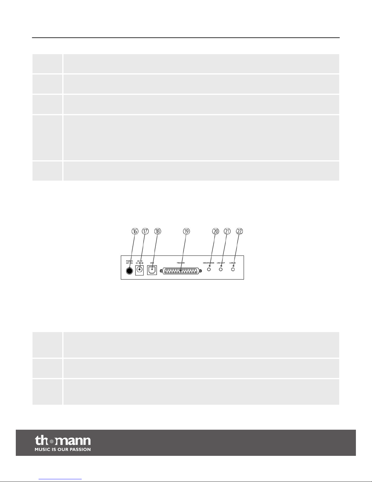
11 [PLAY]
Button for playing back a pattern.
12 [RECORD]
Button for activating the recording mode.
13 [SAVE]
Button for saving a recording.
14 [–]/[+]
Selection / navigation buttons for all menus with forward and fast forward (press and hold down).
Reset function
To reset the drum module to its factory defaults, press and hold down these two buttons during startup of the
device until ‘rES’ appears on the display.
15 Pad selection buttons
[HI-HAT-PEDAL], [HI-HAT], [CRASH], [RIDE], [TOM 1/2/3], [KICK], [SNARE]
16 POWER OFF | ON
Push button for turning the drum module on/off. After switching off the device, wait at least 5 s before switching it
on again (time required for resetting the electronic circuits).
17 DC 9V
Socket for connecting the power supply unit.
18 USB
USB port for connecting a PC with USB interface. The drum module is compatible with Windows® XP, Windows®
Vista and Windows® 7 as well as Apple Macintosh and is recognized as an external audio device by the PC.
Drum module, rear panel
Connections and controls
e-drum set
16
Page 17

19 TRIGGER
25-pin D-sub connector for connecting the pad cable supplied.
20 HEADPHONE
Headphone output (stereo).
21 LINE OUT
Output jack for connecting an active speaker or an amplifier or directly a PA system. When connecting an external
mono system, we recommend using a stereo-to-mono adapter.
22 LINE IN
Input jack for connecting external audio devices such as CD players, MP3 players, etc.
Connections and controls
MPS-250 USB
17
Page 18
8 Operation
8.1 Functions
Before switching on the device, check all cables for proper connection.
Before switching on the device, turn the [MASTER VOLUME] control of the
drum module to its minimum level, and switch off all external devices con‐
nected.
Switch on the drum module using the [ON/OFF] push button.
When the drum module is not used, it will switch off automatically after 20 minutes.
To switch it on again, press the [ON/OFF] push button.
If applicable, switch on any connected active speaker or amplifier and set the volume
control of the external device to a medium level first. To set the output volume of the
drum module, hit a pad while slowly turning the [MASTER VOLUME] control in clock‐
wise direction.
A drum kit is a percussion arrangement where each trigger is assigned a certain voice
and several sound parameters. By selecting a drum kit, you can instantly tailor the
sound of your e-drum set to match the desired style of music. You may also create
and save your own drum kits on the basis of the 20 on-board drum kits (see
Ä
Chapter 11.1 ‘Kit list’ on page 25).
1. After switching on the drum module, the KIT menu opens by default. If another
menu opens, press the [KIT] button to open the KIT menu. The number of the
first drum kit appears on the display.
2. Use the [–] / [+] buttons to select the desired drum kit ( ‘01’ to ‘20’).
You can set the voice and volume of each single trigger of the drum kit.
1. Switch to the KIT menu and select the desired kit using the [–] / [+] buttons.
2. Press the button of the pad to which you want to assign a certain voice and/or
whose volume you want to change. Alternatively you can activate the corre‐
sponding pad also by striking it directly.
3. Press the [VOICE] button to open the VOICE menu, or press the [VOLUME]
button to adjust the pad volume.
ð
The number of the currently set voice or volume appears on the display.
Depending on your selection, the signal LED of either the [VOICE] or the
[VOLUME] button is lit.
4. Using the [–] / [+] buttons, select the desired voice ( ‘1’ to ‘184’), or set the
volume to any desired value between ‘0’ and ‘127’.
Power on
Automatic switchoff
Adjusting the volume
Selecting a drum kit
Adjusting drum kits
Operation
e-drum set
18
Page 19
5. Activate the next pad, or confirm your selection with [SAVE] to permanently
assign the new settings.
If you do not want to permanently save your changes, press either the
[VOICE] or the [VOLUME] button (depending on your previous selection) to
exit the editing mode. All unsaved changes will be lost when you switch off
the drum module.
The drum module comes with 50 different built-in patterns for accompaniment and
practice.
1. Press the [PATTERN] button to open the PATTERN menu. The number of the
first pattern appears on the display.
2. Use the [–] / [+] buttons to select the desired pattern ( ‘P01’ to ‘P50’).
3. Press the [PLAY] button to start playback.
ð
The pattern will be played back in an endless loop until you select another
pattern or terminate playback by pressing the [STOP] button.
You may adjust the pattern playback speed at any moment by means of the [–] / [+]
buttons.
1. Press the [TEMPO] button. The current playback speed appears on the display.
2. Using the [–] / [+] buttons, set the playback speed to any desired value
between ‘40’ and ‘240’.
To reset the playback speed, simultaneously press the [–] / [+] buttons.
You may adjust the pattern playback volume at any moment by means of the [–] / [+]
buttons.
1. Press the [VOLUME] button. The current playback volume appears on the dis‐
play.
2. Using the [–] / [+] buttons, set the playback volume to any desired value
between ‘0’ and ‘127’.
When practicing, you can mute the pattern’s drum track ([DRUM OFF]
button).
Selecting a pattern
Operation
MPS-250 USB
19
Page 20
Press the [CLICK] button to activate or deactivate the metronome.
You may adjust the click speed at any moment by means of the [–] / [+] buttons.
1. Press the [TEMPO] button. The current click speed appears on the display.
2. Using the [–] / [+] buttons, set the click speed to any desired value between
‘40’ and ‘240’ .
To reset the click speed to its default value (120 bpm), simultaneously press
the [–] / [+] buttons.
The drum module offers you the possibility of recording a pattern of your own and
saving it as pattern no. ‘051’ on the device. The recording can be done with or
without accompaniment pattern. When recording with an accompaniment pattern,
you can mute the included drum track ([DRUM OFF] button).
Recording without accompaniment pattern
1. Press the [RECORD] button to activate the recording mode.
ð
The signal LED of the [RECORD] button starts flashing. The number of the
first pattern appears on the display. Press the [PATTERN] button to record
without accompaniment ( ‘oFF’ message).
2. Start recording by striking a pad (synchro start).
ð
The signal LED of the [RECORD] button lights up.
3. Terminate your recording by pressing the [STOP] button.
ð
The signal LED of the [RECORD] button goes out.
Recording with accompaniment pattern
1. Press the [RECORD] button to activate the recording mode.
ð
The signal LED of the [RECORD] button starts flashing. The number of the
first pattern appears on the display.
2. Use the [–] / [+] buttons to select the desired accompaniment pattern.
3. Adjust the pattern volume and pattern speed (see ).
4. Start recording by pressing the [RECORD] button (auto start with one 4/4 bar
pre-count).
ð
The signal LED of the [RECORD] button lights up. The pattern will be played
back in an endless loop until you terminate playback by pressing the
[STOP] button and the signal LED of the [RECORD] button goes out.
Metronome
Recording function
Operation
e-drum set
20
Page 21
The accompaniment pattern always plays until the last bar during a
recording, independently of when you terminate your recording.
Recording with metronome
To make the metronome click during a recording, press the [CLICK] button after acti‐
vating the recording mode (signal LED of the button starts flashing). The clicking will
automatically set in with the recording.
The click sound is not recorded.
Terminating and playing back a recording
1. Terminate your recording by pressing either the [RECORD] or the [STOP]
button.
ð
The signal LED of the [RECORD] button is flashing.
2. Save your recording by pressing the [SAVE] button.
ð
The signal LED of the [RECORD] button goes out.
The signal LED of the [PATTERN] button lights up.
‘P51’ appears on the display.
Discarding or overwriting a recording
To discard your recording, press either the [KIT] or the [PATTERN] button to exit the
recording mode.
To overwrite your recording, start a new recording as described above.
8.2 Playing the pads
The bass drum, snare, hi-hat and cymbals of an analog drum set are replaced by pads
here. When you strike a pad, an integrated trigger produces the previously assigned
voice via the drum module. The harder you hit a pad, the louder the sound produced.
Tom pads have only one trigger and must be hit in the center in order to produce a
sound.
Crash and ride pads have only one trigger and must be hit in the slightly thicker
rubber-coated zone to produce a sound.
Toms
Crash and ride
Operation
MPS-250 USB
21
Page 22

The crash pad can be muted with the hand just like an analog cymbal (choke func‐
tion).
The snare pad has two triggers: the center trigger produces the typical snare sound,
while the rim trigger produces rim shots.
The bass drum pad has only one trigger and must be hit in the center to produce a
sound.
n You produce a closed hi-hat sound by keeping the hi-hat pedal depressed while
hitting the hi-hat
n You produce an open hi-hat sound by not pressing the hi-hat pedal while hitting
the hi-hat
n An open hi-hat sound changes smoothly to a closed hi-hat sound when you start
pressing the hi-hat pedal while hitting the hi-hat.
Snare
Bass drum
Hi-hat
Operation
e-drum set
22
Page 23
9 Technical data
Pads 9 velocity-sensitive drum pads, including bass drum pedal and hi-hat pedal
Sounds 184
Drum kits 20 pre-programmed drum kits
Patterns 50 pre-programmed patterns, 1 user-defined pattern
Connections 25-pin D-sub for connecting the pads (pad cable included in delivery)
USB
LINE IN / LINE OUT (3.5 mm jack connectors)
Headphones (3.5 mm jack connector)
Mains power supply
9 V power supply unit
Technical data
MPS-250 USB
23
Page 24
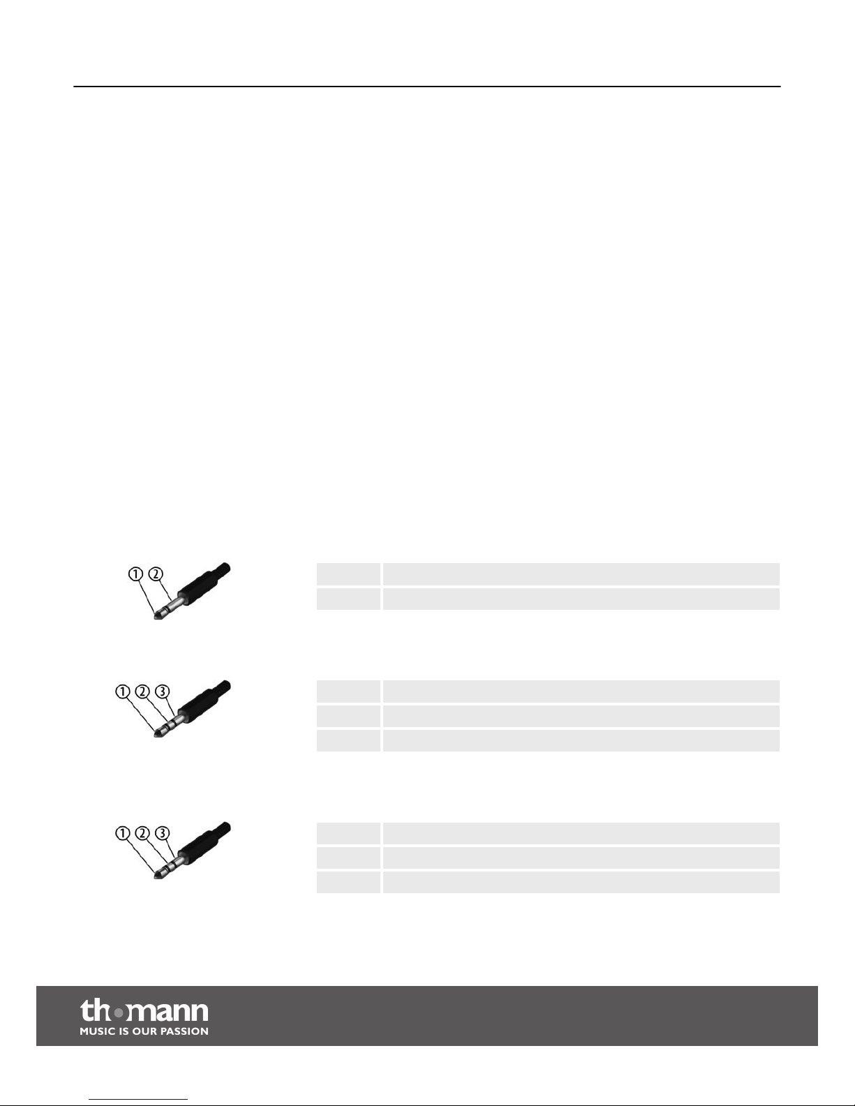
10 Connector and pin assignments
This chapter will help you select the right cables and plugs to connect your valuable
equipment in such a way that a perfect sound experience is ensured.
Please note these advices, because especially in ‘Sound & Light’ caution is indicated:
Even if a plug fits into the socket, an incorrect connection may result in a destroyed
power amp, a short circuit or ‘just’ in poor transmission quality!
Unbalanced transmission is mainly used in semi-professional environment and in hifi
use. Instrument cables with two conductors (one core plus shielding) are typical rep‐
resentatives of the unbalanced transmission. One conductor is ground and shielding
while the signal is transmitted through the core.
Unbalanced transmission is susceptible to electromagnetic interference, especially at
low levels, such as microphone signals and when using long cables.
In a professional environment, therefore, the balanced transmission is preferred,
because this enables an undisturbed transmission of signals over long distances. In
addition to the conductors ‘Ground’ and ‘Signal’, in a balanced transmission a second
core is added. This also transfers the signal, but phase-shifted by 180°.
Since the interference affects both cores equally, by subtracting the phase-shifted
signals, the interfering signal is completely neutralized. The result is a pure signal
without any noise interference.
1 Signal
2 Ground
1 Signal (in phase, +)
2 Signal (out of phase, –)
3 Ground
1 Signal (left)
2 Signal (right)
3 Ground, shielding
Introduction
Balanced and unbalanced transmis‐
sion
1/4" TS phone plug (mono, unbal‐
anced)
3.5 mm TRS phone plug (mono, bal‐
anced)
Three-pole 1/8" mini phone jack
(stereo, unbalanced)
Connector and pin assignments
e-drum set
24
Page 25
11 Appendix
11.1 Kit list
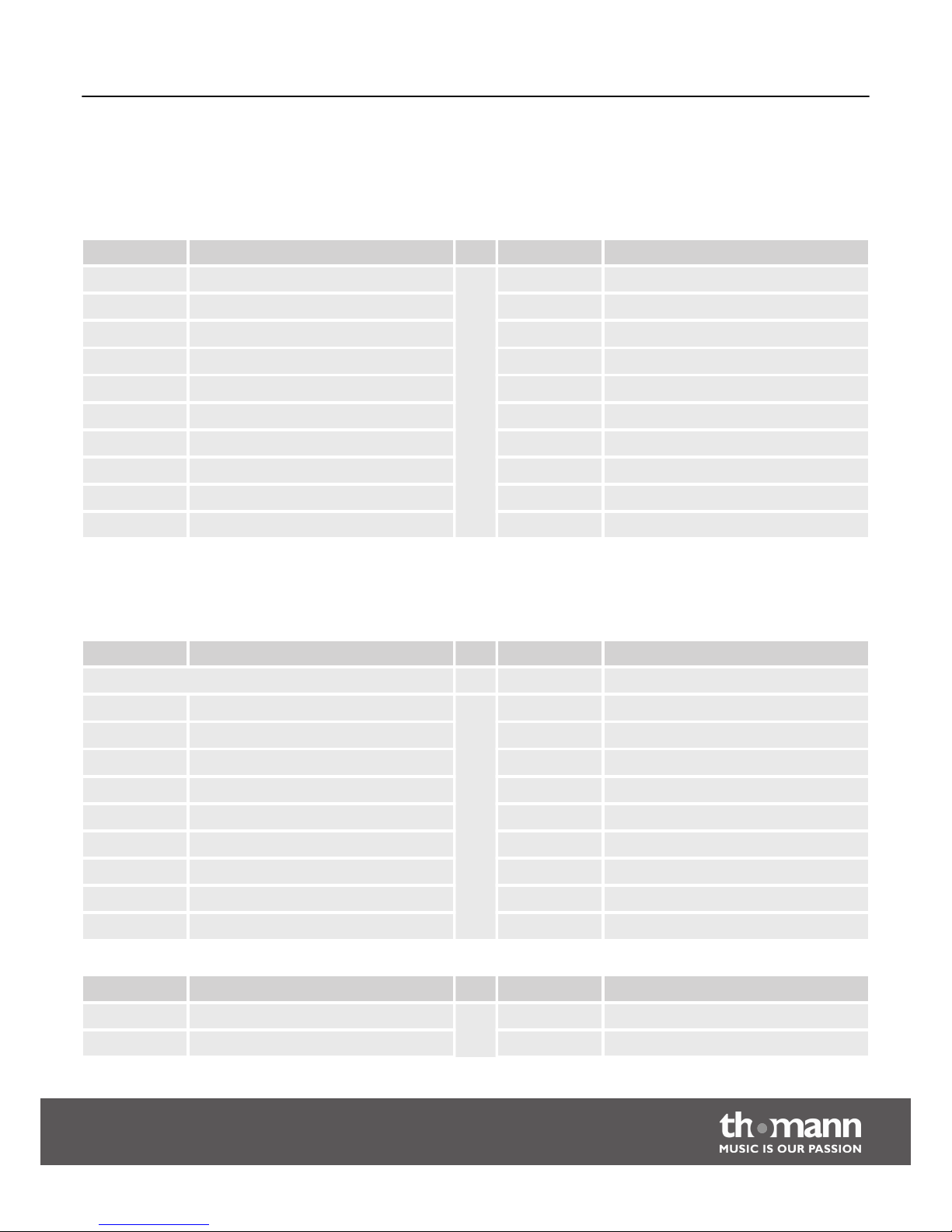
No. Name No. Name
01 Pop 11 HeavyBeat
02 Electric 12 Metal
03 Jazz 13 Rock
04 BeatBox 14 Punk
05 808 15 Carbon
06 Fireball 16 Disco
07 Magnet 17 TightRope
08 Dry 18 Smashing
09 Machine 19 Largeness
10 Room 20 Funky
11.2 Voice list
No. Description No. Description
GM 010 KickDrum1
001 HighQ 011 SideStick
002 Slap 012 SnareDrum2
003 ScraPush 013 HandClap
004 ScraPull 014 SnareDrum1
005 Stick 015 LoFloTom2
006 SquarClick 016 CloseHH
007 MetroClick 017 LowFloTom1
008 MetroBell 018 PedalHH
009 KickDrum2 019 LowTom
No. Description No. Description
020 OpenHi-hat 033 RideCymb2
021 Low-midTom 034 HiBongo
Appendix
MPS-250 USB
25
Page 26
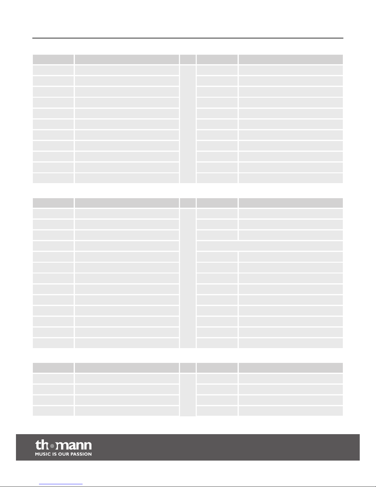
No. Description No. Description
022 Hi-midTom 035 LowBongo
023 CrashCymb1 036 MuteConga
024 RHighTom 037 HiConga
025 RideCymb1 038 LowConga
026 ChCymbal 039 HighTimbal
027 RideBell 040 LowTimbale
028 Tambourine 041 HighAgogo
029 SplashCymb 042 LowAgogo
030 Cowbell 043 Cabasa
031 CrashCymb2 044 Maracas
032 VibraSlap 045 ShortWhist
No. Description No. Description
046 LongWhist 059 Castanets
047 ShortGuiro 060 MuteSurdo
048 LongGuiro 061 OpenSurdo
049 Claves KICK
050 Hi W-Block 062 Kick 1
051 Lo W-Block 063 Kick 2
052 MuteCuica 064 Kick 3
053 OpenCuica 065 Kick 4
054 MuteTriang 066 Kick 5
055 OpenTriang 067 Kick 6
056 Cabasa 068 Kick 7
057 Shaker 069 Kick 8
058 Belltree 070 Kick 9
No. Description No. Description
071 Kick 10 083 Snare 3
072 Kick 11 084 Snare 4
073 Kick 12 085 Snare 5
074 Kick 13 086 Snare 6
Appendix
e-drum set
26
Page 27
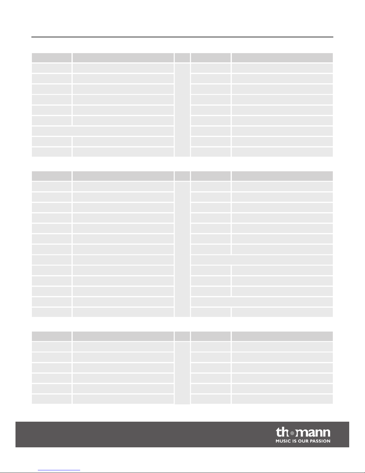
No. Description No. Description
075 Kick 14 087 Snare 7
076 Kick 15 088 Snare 8
077 Kick 16 089 Snare 9
078 Kick 17 090 Snare 10
079 Kick 18 091 Snare 11
080 Kick 19 092 Snare 12
SNARE 093 Snare 13
081 Snare 1 094 Snare 14
082 Snare 2 095 Snare 15
No. Description No. Description
096 Snare 16 109 Snare 29
097 Snare 17 110 Snare 30
098 Snare 18 111 Snare 31
099 Snare 19 112 Snare 32
100 Snare 20 113 Snare 33
101 Snare 21 114 Snare 34
102 Snare 22 115 Snare 35
103 Snare 23 SIDE STICK
104 Snare 24 116 SideStick 1
105 Snare 25 117 SideStick 2
106 Snare 26 118 SideStick 3
107 Snare 27 CLOSED HI-HAT
108 Snare 28 119 Closed Hi-Hat 1
No. Description No. Description
120 Closed Hi-Hat 2 132 Open Hi-Hat 2
121 Closed Hi-Hat 3 133 Open Hi-Hat 3
122 Closed Hi-Hat 4 134 Open Hi-Hat 4
123 Closed Hi-Hat 5 135 Open Hi-Hat 5
124 Closed Hi-Hat 6 136 Open Hi-Hat 6
125 Closed Hi-Hat 7 137 Open Hi-Hat 7
Appendix
MPS-250 USB
27
Page 28
No. Description No. Description
126 Closed Hi-Hat 8 138 Open Hi-Hat 8
127 Closed Hi-Hat 9 139 Open Hi-Hat 9
128 Closed Hi-Hat 10 140 Open Hi-Hat 10
129 Closed Hi-Hat 11 141 Open Hi-Hat 11
130 Closed Hi-Hat 12 142 Open Hi-Hat 12
OPEN HI-HAT 143 Open Hi-Hat 13
131 Open Hi-Hat 1
No. Description No. Description
HI TOM 155 Mid Tom 4
144 Hi Tom 1 156 Mid Tom 5
145 Hi Tom 2 157 Mid Tom 6
146 Hi Tom 3 158 Mid Tom 7
147 Hi Tom 4 159 Mid Tom 8
148 Hi Tom 5 LOW TOM
149 Hi Tom 6 160 Low Tom 1
150 Hi Tom 7 161 Low Tom 2
151 Hi Tom 8 162 Low Tom 3
MID TOM 163 Low Tom 4
152 Mid Tom 1 164 Low Tom 5
153 Mid Tom 2 165 Low Tom 6
154 Mid Tom 3 166 Low Tom 7
No. Description No. Description
167 Low Tom 8 176 Ride 6
CRASH OTHER PERCUSSION
168 Crash 1 177 Percussion 1
169 Crash 2 178 Percussion 2
170 Crash 3 179 Percussion 3
RIDE 180 Percussion 4
171 Ride 1 181 Percussion 5
172 Ride 2 PEDAL HI-HAT
Appendix
e-drum set
28
Page 29
No. Description No. Description
173 Ride 3 182 Pedal Hi-Hat 1
174 Ride 4 183 Pedal Hi-Hat 2
175 Ride 5 184 Pedal Hi-Hat 3
11.3 MIDI implementation
Function Transmitted Recognized Remarks
Basic channel 10 1-16
Note number 0-127 0-127
Velocity Note ON 1-127 0-127
Note OFF 64 0-127
Major Controls B9h 04h xxh Yes No Hi-Hat pedal control
Bxh 79h 00h Yes Yes Reset All Controller
Bxh 7Bh 00h Yes Yes All Notes OFF
Programme Change No Yes
System Exclusive Yes Yes
RPN No Yes
NRPN Yes Yes
Channel 10 supports only Bank 0.
For more information regarding “System Exclusive”, “RPN” and “NRPN”,
please contact your specialized dealer.
Instrument Note Instrument Note
Tom 1 48 Ride 51
Tom 2 45 Hi-Hat Open 46
Tom 3 41 Hi-Hat Close 42
Snare 38 Hi-Hat Pedal 44
Snare Rim 37 Kick 36
Crash 55
Appendix
MPS-250 USB
29
Page 30

12 Cleaning
Clean the accessible parts of the device regularly. The frequency of cleaning depends
on the operating environment: moist, smoky or particularly dirty environments may
cause a higher accumulation of dirt on the components of the device.
n Use a dry soft cloth for cleaning.
n Remove stubborn stains with a slightly damp cloth.
n Never use cleaners containing alcohol or thinner.
n Never put any vinyl items on the device, as vinyl can stick to the surface or lead
to its discolouration.
Device parts
Cleaning
e-drum set
30
Page 31
13 Protecting the environment
For the transport and protective packaging, environmentally friendly materials have
been chosen that can be supplied to normal recycling.
Ensure that plastic bags, packaging, etc. are properly disposed of.
Do not just dispose of these materials with your normal household waste, but make
sure that they are collected for recycling. Please follow the notes and markings on
the packaging.
This product is subject to the European Waste Electrical and Electronic Equipment
Directive (WEEE). Do not dispose with your normal household waste.
Dispose of this device through an approved waste disposal firm or through your local
waste facility. When discarding the device, comply with the rules and regulations
that apply in your country. If in doubt, consult your local waste disposal facility.
Disposal of the packaging material
Disposal of your old device
Protecting the environment
MPS-250 USB
31
Page 32

Notes
e-drum set
32
Page 33

Notes
MPS-250 USB
33
Page 34

Notes
e-drum set
34
Page 35

Page 36

Musikhaus Thomann e.K. · Treppendorf 30 · 96138 Burgebrach · Germany · www.thomann.de
 Loading...