

Millcreek TURF TIGER Operator's Manual

OPERATOR'S MANUAL
MILLCREEK MODELS:
3100/3200 TURF TIGER® SPREADERS
PUBLICATION DATE: 1/13/09, Rev. 3 MILLCREEK PART # 43827
WARNING: DO NOT assemble, operate, or maintain this equipment without first
reading and understanding the information provided in this manual and the
ADMA Safety Manual for Agricultural Implement Drivelines. Failure to follow
all safety precautions as stated in these manuals may result in serious personal injury
or death.
I-86219
Millcreek Manufacturing Company
34 Zimmerman Road
Leola, PA 17540
Phone: 1-800-311-1323 / Fax: 717-656-0952
www.millcreekmfg.com


W ARRANTY INFORMATION
Millcreek Manufacturing Company (hereinafter called the Company) warrants to the original Purchaser, the
Equipment, manufactured by the Company, to be free from defects in material and workmanship under normal
use and service. The Company warrants the construction of the equipment sold herein and will replace at the
Company's expense for a period of two years from the date of delivery to the original Purchaser, any parts which
prove defective as determined under the terms of this Limited Warranty. The Company obligation under this
Warranty shall be limited to replacement or repair of any parts thereof, free of charge, to the original Purchaser,
provided, however, that the part(s) to be replaced or repaired, shall, within two years after delivery to the original
Purchaser, be demonstrated to be defective; which determination shall be made by the Company. The said
components or parts must be returned through the Selling Dealer or Distributor directly to the Company with all
transportation charges prepaid. Notice of defect shall be furnished in writing to the Seller and to the agent through
whom the machinery was purchased, disclosing in full all known defects and failure in operation and use.
Reasonable time shall be given to the Seller to remedy any such defects and failures.
Likewise, a ten (10) year, pro-rated warranty is provided on the spray-on polyurethane lining (applied to internal
sides of unit, excluding exterior non-lined surfaces). The high density, polyethelene floorboards are warranted for the
lifetime of the machine from cracking, rotting, splitting, or peeling.
This Warranty does not cover, under any circumstances, any parts, components, or materials which, in the opinion
of the Seller and the Company, have been subjected to neglect, misuse, alteration, accident, or repaired with parts
other than those manufactured by and obtained from Millcreek Manufacturing Company.
This Warranty does not cover components which are already covered by a separate warranty provided by the
supplier of said parts or components.
This Warranty is made in lieu of all other warranties, expressed or implied, including any warranty of
merchantability and fitness for use and purpose and of all other obligations or liabilities on the Company
part and any implied warranty. The Company neither assumes nor authorizes any other person to assume
for it, any other liability in connection with the sale of this equipment. This Warranty shall not apply to
this equipment or to any part thereof which has been subjected to accident, negligence, alteration, abuse,
or misuse.
The Company makes no warranty whatsoever in respect to accessories or parts not supplied by the Company.
The term "original Purchaser," as used in this Warranty, shall be deemed to mean that person for whom the
equipment is originally supplied. This Warranty shall apply only within the boundaries of the continental United
States.
Under this Warranty, the Company cannot guarantee that conditions existing beyond its control will not affect the
Company's ability to obtain materials or manufacture necessary replacement parts.
The Company reserves the right to make design changes, or changes in specifications at any time, without any
contingent obligation on the part of the Company to purchasers of machines and parts previously sold.
TRADEMARKS
The Millcreek logo is a trademark of the Millcreek Manufacturing Company. All other brand or product names
mentioned are the registered trademarks or trademarks of their respective owners.
COPYRIGHT
Copyright © 2009 Millcreek Manufacturing Company. All rights reserved. No part of this publication may be
reproduced, or distributed without the prior written permission of Millcreek Manufacturing Company, 34 Zimmerman
Road, Leola, PA 17540. Subject to change without notice.


TABLE OF CONTENTS
SECTION 1: INTRODUCTION ................................................................................... 1-1
Guide to this Manual ..........................................................................................................1-1
For Your Safety... ..............................................................................................................1-1
Safety Labels ..............................................................................................................1-2
Inspection and Warranty Registration..................................................................................1-5
Warranty Registration ..................................................................................................1-5
SECTION 2: ATTACHING THE SPREADER TO THE TRACTOR............................ 2-1
Connecting the Spreader Hitch to the Tractor Drawbar ......................................................2-1
Attaching the Spreader to the Tractor PTO.........................................................................2-2
SECTION 3: OPERATION & ADJUSTMENT ............................................................ 3-1
Understanding TURF TIGER® Spreader Operation ............................................................3-1
TURF TIGER Spreader Operating Components ..........................................................3-1
Guidelines for Loading the TURF TIGER Spreader......................................................3-1
Operating the TURF TIGER Spreader ...............................................................................3-1
Adjusting the TURF TIGER Spreader ................................................................................3-2
Adjusting Tractor Ground Speed .................................................................................3-2
Adjusting the Metering Endgate ...................................................................................3-2
Recommended Settings for TURF TIGER Spreader Operation ...........................................3-3
Material Weights (Range Per Cubic Yard) ...................................................................3-3
Material Volume Estimation .........................................................................................3-3
Initial Adjustments (Sample Settings)............................................................................3-4
SECTION 4: MAINTENANCE & ADJUSTMENT ....................................................... 4-1
Guidelines for Regular Maintenance ....................................................................................4-1
General Maintenance ...................................................................................................4-1
Wheel/Tire Maintenance ..............................................................................................4-1
Wheel Bearing Maintenance ........................................................................................4-2
Procedures for Spreader Adjustment ..................................................................................4-2
Checking and Adjusting the Floor Apron Chain............................................................4-2
Checking and Adjusting the Apron Drive Chains ..........................................................4-3

TABLE OF CONTENTS
APPENDIX A: PARTS REFERENCE .........................................................................A-1
General TURF TIGER® Spreader Specifications................................................................A-1
Component Parts Ordering Information ............................................................................. A-2
TURF TIGER Spreader Box and Hitch Assembly ............................................................. A-2
TURF TIGER Spreader Wheel/Hub Assembly .................................................................. A-4
TURF TIGER Rear Drive Assembly..................................................................................A-6
TURF TIGER Front Drive Assembly.................................................................................A-8
TURF TIGER Apron Chain and Sprocket Assembly ....................................................... A-10
TURF TIGER Safety Shields and Guards ........................................................................ A-12
TURF TIGER PTO Shaft Assembly ................................................................................ A-14
TURF TIGER Metering Endgate Assembly ..................................................................... A-16
APPENDIX B: OPTIONAL PARTS REFERENCE ..................................................... B-1
Safety Chain Assembly...................................................................................................... B-1
Pathmaker Assembly......................................................................................................... B-2
Pathmaker Mounting Instructions ................................................................................ B-2
Slow Moving Vehicle Sign................................................................................................. B-4
APPENDIX C: ENGINE DRIVE...................................................................................C-1

Operator's Manual: Millcreek 3100/3200 TURF TIGER® Spreaders
SECTION 1: INTRODUCTION
Guide to this Manual
This manual contains all the information necessary to safely operate and maintain the Millcreek Model 3100 and
®
3200 TURF TIGER
find this manual's step-by-step procedures easy to follow and understand. Should questions arise, please
contact your Millcreek dealer before starting any of the procedures in this manual.
NOTE: Procedures provided in this manual apply to both spreader models (Model 3100 and Model
3200) unless specifically noted otherwise.
Regarding the information presented in this manual:
• All safety, operating, and servicing information reflects current production models at the time
of publication of this manual.
• References made to left, right, front, and rear are those directions viewed when facing the
unit from the rear.
Spreaders. Consult the Table of Contents for a detailed list of topics covered. You'll
Please read all sections in the manual carefully--including the important safety information found in
this section--before beginning any assembly/operation procedures; doing so allows you to use your
Millcreek Spreader safely with optimal performance.
For Your Safety...
For your safety, Millcreek documentation contains the following types of safety statements (listed here
in order of increasing intensity):
• NOTE: A clarification of previous information or additional pertinent information.
• ATTENTION: A safety statement indicating that potential equipment damage may occur if
instructions are not followed.
CAUTION: A safety statement that reminds of safety practices or directs attention to unsafe
practices which could result in personal injury if proper precautions are not taken.
WARNING: A strong safety statement indicating that a hazard exists which can result in
injury or death if proper precautions are not taken.
DANGER! The utmost levels of safety must be observed; an extreme hazard exists which
would result in high probability of death or irreparable serious personal injury if proper
precautions are not taken.
The best operator is a careful operator. By using common sense, observing general safety rules, and
adhering to the precautions specific to the spreader, you, the operator, can promote safe equipment
operation.
1-1

Operator's Manual: Millcreek 3100/3200 TURF TIGER® Spreaders
For Your Safety... (continued)
In addition to observing the specific precautions listed throughout the manual, the following general
precautions apply and must be heeded for proper, safe operation.
WARNING: Keep hands and feet from under the spreader at all times. Ensure that you are
safely distanced from any other persons before operating the spreader.
WARNING: DO NOT attempt to operate the spreader in areas with steep inclines, ditches,
large rocks, stumps, or holes which may endanger the operator by upsetting the tractor or cause
damage to the spreader.
WARNING: To prevent serious personal injury and to promote safe spreader operation, keep all
shields in place during operation. Ensure that all mounting hardware is properly tightened.
WARNING: Never clean, adjust, or repair the spreader while the tractor is running.
WARNING: Never get off the tractor while it is in motion, while the spreader is in operation,
and/or while the PTO is engaged.
WARNING: Never wear loose clothing when operating the spreader as it may become caught
in the moving parts of the machine.
WARNING: Never allow children or anyone else to ride on the spreader.
ATTENTION: For proper and safe operation of the spreader, periodically inspect all parts for
excessive wear. Replace worn components with factory-authorized parts.
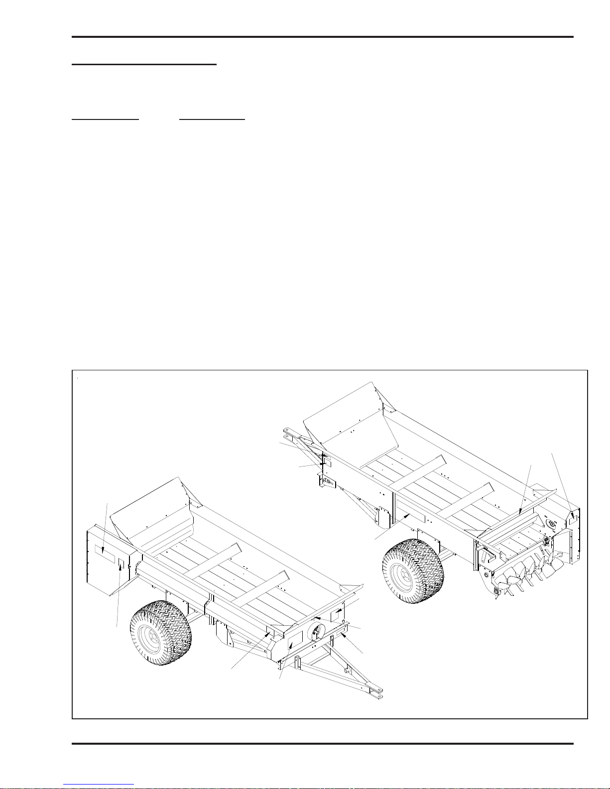
Safety Labels
Following are the locations and descriptions of all labels on your TURF TIGER spreader. Figure 1A shows
the location of ALL labels on your spreader. Please note that some labels denote model number, model
description, etc. while others contain important safety messages.
Each Safety Label contains an important safety message starting with a key word as discussed earlier in this
section (e.g. ATTENTION, CAUTION, WARNING, DANGER). For your safety and the safe operation of
your spreader, review all labels and heed all safety messages as printed on the labels.
Be sure to keep the safety labels clean and readable. If the labels ever become damaged or illegible,
contact your Millcreek dealer for replacements.
1-2
Operator's Manual: Millcreek 3100/3200 TURF TIGER® Spreaders
Safety Labels (continued)
TURF TIGER Spreader Safety Labels
Label Part # Description
42792 DANGER - NO riders
42710 WARNING - Flying Debris
42756 WARNING - Entanglement, Do NOT operate without shields
42772 WARNING - Spreader combination safety label - moving parts, read manual
42778 Millcreek Logo Label
42781 Model 3100 Serial Number Label
42782 Model 3200 Serial Number Label
42788 Model 3100 Label
42789 Model 3200 Label
42790 TURF TIGER Spreader Logo Label
42810 Model 3100 Load Limit Label
42811 Model 3200 Load Limit Label
For your safety, be sure to locate all safety labels and review their content before proceeding with
operating the spreader!
3100-42781
3200-42782
3100-42810
3200-42811
42790
42790
42772
42710
42792
42756
Under Shield
42810-3100
42811-3200
42778
Figure 1A - Safety Label Locations
1-3
42792
42788-3100
42789-3200
I-86220

Operator's Manual: Millcreek 3100/3200 TURF TIGER® Spreaders
Safety Labels (continued)
NO RIDERS
Moving parts can crush or cut.
STAY CLEAR of machine while engine is
running and/or machine is operating.
Keep hands, feet, clothing, and hair away from
operating parts.
Never adjust, lubricate, or clean machine while
engine is running and/or machine is operating.
Never operate machine without safety shields in
place.
Read and understand operator's manual and
safety labels before operating or servicing the
machine.
42792
Entanglement Hazard.
DO NOT OPERATE without
safety shield in place. Moving
parts can crush and cut.
42756
Failure to follow these warnings may result in
serious injury or death.
Entanglement / Flying Debris
Hazards.
DO NOT STAND in back of machine
while engine is running and/or machine
is operating. Rotating beaters and/or
flying de bris can cause serious personal
injury or death.
Approach the rear of the maching ONLY
when all power sources are shut OFF and
all moving parts have stopped.
42710
DO NOT EXCEED
3000 lbs PAYLOAD
10 mph max loaded
Model 3100
DO NOT EXCEED
3750 lbs PAYLOAD
10 mph max loaded
Model 3200
1-4

Operator's Manual: Millcreek 3100/3200 TURF TIGER® Spreaders
Inspection and Warranty Registration
Most spreader models are shipped from your Millcreek Dealer completely assembled and ready for operation.
Inspect your new spreader thoroughly upon receipt to ensure that it has been shipped to you in a satisfactory
manner. Immediately notify the freight company and your Millcreek dealer in case of shipping damage,
shortage(s), and/or errors.
The TURF TIGER Spreader is supplied with the following operating features/components (standard):
• Adjustable Metering Gate
• Loading Flares
• PTO Shaft
• Jack
• 26.5 x 14 x 12 (4-ply) Turf Tires
NOTE: If the spreader has not been pre-assembled, please refer to the Supplemental Assembly
Instructions. Please contact your local Millcreek Dealer for assistance as needed.
Your spreader shipment may also include the following options:
• Safety Chain
• Slow Moving Vehicle Sign
• Pathmaker
• Engine Drive*
Instructions for assembling these items are provided in Appendix B and C at the back of this manual. Please
contact your local Millcreek Dealer for assistance as needed.
*NOTE: If you ordered a Model 3100 Engine Drive, please also refer to the Supplemental Instructions,
Millcreek Part #43837, for additional important information about the operation of that unit.
Following inspection of your new spreader, locate the Millcreek Warranty Card in the literature packet
shipped with your spreader. For proper warranty registration, Millcreek requires that you fill out the warranty
registration card and return it within 30 days to:
MILLCREEK WARRANTY REGISTRATION
Millcreek Manufacturing Company
34 Zimmerman Road
Leola, PA 17540
For your safety, be sure to locate all safety decals and review their content before proceeding with
operating the spreader.
1-5

Operator's Manual: Millcreek 3100/3200 TURF TIGER® Spreaders
1-6
Operator's Manual: Millcreek 3100/3200 TURF TIGER® Spreaders
SECTION 2: ATTACHING THE SPREADER
TO THE TRACTOR
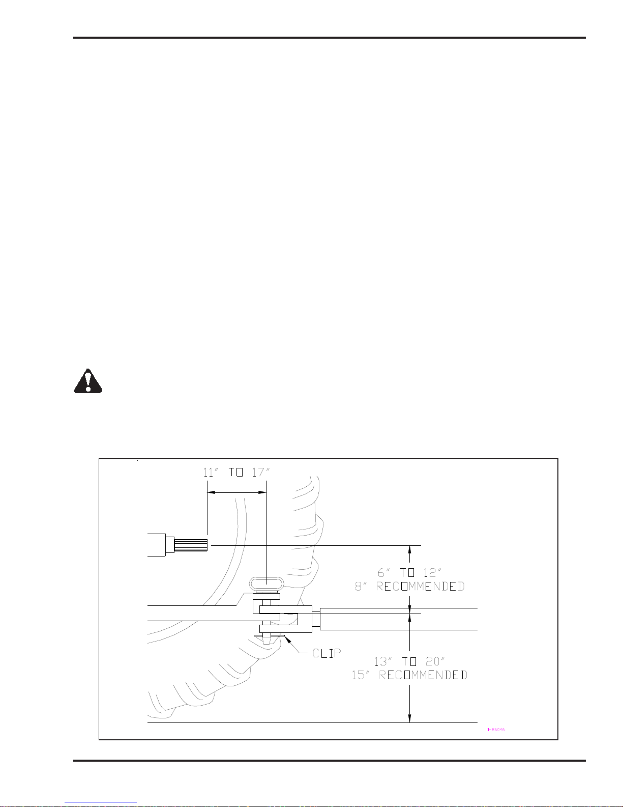
Connecting the Spreader to the Tractor
The spreader hitch is designed to work with a standardized tractor hitch. To connect the spreader hitch to the
tractor hitch, refer to Figure 2A and adhere to the following guidelines:
• Adjust the drawbar so that it is 13 to 20 inches above the ground as shown in Figure 2A.
• For PTO units only: Extend or shorten the tractor hitch to obtain the horizontal distance from the
end of the tractor power take-off (PTO) shaft to the center of the hitch pin hole (Figure 2A).
• Adjust the height of the spreader hitch with the jack so the tractor drawbar matches the height
of the spreader hitch.
• Back the tractor into the hitch until the holes line up.
• Fasten the spreader hitch to the drawbar with a hitch pin that fits securely (i.e. so that it will
not come out during spreader operation) and lock in place with the clip as shown.
• Remove the weight from the jack by lowering the spreader hitch on the drawbar.
• Swing the jack to its horizontal position and lock it in position to provide maximum ground
clearance.
• ATTENTION: Be sure the 3-point hitch brackets on the tractor are adjusted to clear the
spreader hitch while turning, or equipment damage may occur.
WARNING: Damage to the spreader or other vehicle, as well as injury to the operator, may occur if
a properly-sized hitch pin is not installed as recommended. Note that the installation of the safety clip,
as noted in Figure 2A, is also required for safe spreader operation.
ATTENTION: An improperly located hitch point may cause damage to the universal joints of the PTO. The
recommended length of the PTO shaft should range from 36 to 51 inches center to center of the "U" joints.
Figure 2A - Specifications for Connecting the Spreader/Tractor Hitch
2-1

Operator's Manual: Millcreek 3100/3200 TURF TIGER® Spreaders
Attaching the Spreader PTO to the Tractor PTO
NOTE: If you have a Model 3100 Engine Drive, these instructions do NOT apply.
1. Release the ball bungee that secures the PTO to the PTO Holder.
2. Fold down the PTO Holder so it lays against the hitch.
CAUTION: Failure to fold down the PTO Holder before the PTO is connected to the tractor will
result in equipment damage.
3. Align the PTO splines on the spreader with the PTO splines on the tractor.
4. Pull back the slide collar on the PTO yoke, and slide the spreader PTO assembly onto the
tractor PTO shaft. Be sure the slide collar snaps forward to indicate that the spreader PTO
assembly is properly secured to the tractor PTO shaft.
WARNING: Make sure that the PTO safety chain is attached to one of the hitch brackets on the front
of the spreader (fasten to upper unused hole in bracket). Failure to secure the PTO safety chain
will allow the safety shield to rotate. Operating the spreader without the safety shield in proper position
may result in serious personal injury or death.
2-2

Operator's Manual: Millcreek 3100/3200 TURF TIGER® Spreaders
SECTION 3: OPERATION & ADJUSTMENT
Understanding TURF TIGER® Spreader Operation
Proper and safe operation of the Millcreek 3100/3200 TURF TIGER spreaders requires: (1) being familiar
with the spreader operating components and (2) heeding all safety precautions as stated in this manual.
NOTE: If you have a Model 3100 Engine Drive, be sure to also review the important information on operation
(specific to that unit) provided in the separate addendum, Millcreek Part #43837. Please disregard any
discussion in the following pages with regard to PTO shafts or PTO operation.
TURF TIGER Spreader Operating Components
The TURF TIGER spreaders are supplied standard with a PTO shaft, which is powered through the tractor
drive train. The PTO powers the apron chain and the beater. For further information on engaging the PTO
drive line, please refer to the following section, Operating the TURF TIGER Spreader.
The standard adjustable metering endgate is easy to open/close and adjust as needed for the desired
spreading application.
Guidelines for Loading the Spreader for Operation
• Maximum TURF TIGER payload is 3,000 pounds for Model 3100 and 3,750 pounds for
Model 3200.
• ATTENTION: NEVER store material in the spreader between unloading times during critical cold
weather months when a frozen load could result in severe equipment damage (i.e. torn floor apron
chain). DO NOT store wet material in the spreader (or keep the spreader oudoors with material in
it)--doing so will accelerate rusting of the steel. Be aware that storing material in the spreader also
makes the material difficult to unload (i.e. it may solidify/harden).
Operating the TURF TIGER Spreader
WARNING! Before proceeding with operation of the spreader, review all safety
statements as provided in Section 1 of this manual.
WARNING: To prevent serious personal injury, ensure that ALL safety shields are in place on the
spreader before starting operation. NEVER operate the spreader without ALL safety shields in place.
WARNING: To prevent serious personal injury and/or equpiment damage, DO NOT exceed 10 mph
when transporting a loaded spreader.
1. Load the spreader according to the guidelines provided in this section.
2. Determine the desired opening of the adjustable metering endgate (up to 7 inches), according to
the desired spreading application. Please refer to the Recommended Settings charts provided at
the end of this section.
(Procedure continued on the following page.)
3-1

Operator's Manual: Millcreek 3100/3200 TURF TIGER® Spreaders
Operating the TURF TIGER Spreader
3. Activate the PTO (this action may vary by tractor):
For newer tractors: with the tractor at idle, simply activate the switch to engage the PTO.
ATTENTION: DO NOT engage the PTO while running at full throttle; doing so may tear
the front drive belt or cause it to jump off the pulley.
For older tractors: With the tractor at idle, decompress the clutch and activate the tractor PTO lever.
Release the clutch slowly so the PTO shaft will start the spreader paddles and apron chain.
NOTE: To prevent "piling up" of material (or premature discharge) at initial startup, put the tractor in
gear and begin forward motion immediately.
4. For best results, run the tractor throttle at the 540 rpm PTO shaft speed and regulate the ground
speed to no more than 6 mph.
5. Observe the spreading application and determine if adjustments are required. If adjustments are
desired, please refer to the following information for Adjusting the TURF TIGER. The variables
affecting the application rate are (a) tractor ground speed and (b) metering gate opening.
6. When the spreader box is empty, stop the PTO by disengaging the lever/switch on the tractor and lower
the endgate.
7. Refer to Section 4 in this manual for maintenance to be performed following operation of the
spreader.
IMPORTANT! Be aware that it may be necessary to re-tighten bolts after a few hours of initial
operation -- watch and listen for any loose components. Be sure to check the wheel bolts for proper
torque (75-80 ft. lbs.)
CAUTION: When spreading sand, be sure to make a "dry run" every third load to
allow accumulated sand to dislodge from the apron chain. Failure to do so will result
in extreme tension in the chain, which may cause serious damage to the unit.
Adjusting the TURF TIGER Spreader for Optimal Operation
Adjusting Tractor Ground Speed
Using the tachometer on the tractor, select the tractor gear that will give you the desired ground speed (mph)
with the engine speed delivering 540 RPM (PTO speed), which is required for all TURF TIGER spreader
models. Ground speed can range from 2 to 8 mph, depending on the desired application rate.
Adjusting the Metering Endgate
The maximum opening for the metering endgate is 7 inches. The recommended endgate setting for
normal operation is 3 to 6 inches.
To adjust the opening of the metering endgate:
• Push down on the spring-loaded lever and HOLD.
• Use the handle on the metering gate to rotate the gate to the desired opening.
• Release the spring-loaded lever to lock the metering gate in the desired position.
3-2

Operator's Manual: Millcreek 3100/3200 TURF TIGER® Spreaders
Recommended Settings for TURF TIGER Spreader Operation
CAUTION: For safe operation of the Turf Tiger spreader, DO NOT exceed the load capacities for
the materials listed in the following charts/specifications. The maximum payload is 3,000 pounds for
Model 3100 and 3,750 pounds for Model 3200.
Material Weights (Range Per Cubic Yard)
Spreader
Model
Model 3100 or
3200 with
Loading Flares
(hauling 2-3 cubic
yards)
Material
Sand 2000 lbs./cu. yd. 2700 lbs./cu. yd. 1.1 cu. yd. 1.3 cu. yd.
Topdress Mix
(80% sand + 20% peat)
Compost 900 lbs./cu. yd. 1800 lbs./cu. yd. 1.6 cu. yd. 2.0 cu. yd.
Mulch 600 lbs./cu. yd. 1400 lbs./cu. yd. 2.1 cu. yd. 2.6 cu. yd.
Material Consistency Max. Weight
Dry Wet
1600 lbs./cu. yd. 2200 lbs./cu. yd. 1.3 cu. yd. 1.7 cu. yd.
Material Volume Estimation
Conversion Factors: One cubic yard = 27 cubic feet
One square yard = 9 square feet
Estimation Formula: Cubic yards of material required to cover a specified area
Area to cover X Material X 0.0031 = Cubic Yards of Material
(square feet) (depth in inches) Needed
Max. Yds. (Wet)
Model
3100
Model
3200
Quantity Needed to Cover Depth of Material
1,000 Square Feet One Acre
1/8” 0.375 cubic yds. 17 cubic yds.
1/4" 0.75 cubic yds. 34 cubic yds.
1/2" 1.5 cubic yds. 67 cubic yds.
1” 3.0 cubic yds. 134 cubic yds.
2” 6.0 cubic yds. 269 cubic yds.
3” 9.0 cubic yds. 402 cubic yds.
Example: Determine the amount of material needed to cover 5,000 square feet with a 1/2" depth.
(5,000) X (0.5 inches) X 0.0031 = 7.75 cubic yards
3-3
 Loading...