

Page 1

MPVS Ultra
Signal Conditioning
Hardware
User Guide
1
Page 2

User Guide
Table of Contents
I. Introduction ................................................................................................. 2
II. Getting Started ............................................................................................ 4
Components and Contents ................................................................................................. 4
Initial Setup ........................................................................................................................ 4
Normal Operation............................................................................................................... 8
III. Detailed Operation .................................................................................... 11
Hardware Connections ..................................................................................................... 11
Catheter Configuration tab ............................................................................................... 13
Catheter Calibration Tab .................................................................................................. 18
Rho Cuvette Tab .............................................................................................................. 21
IV. Theory of Operation .................................................................................. 25
The Conductance Method ................................................................................................ 25
Dual Field Excitation ....................................................................................................... 26
Resistivity – Rho Cuvette ................................................................................................ 27
Resistivity – Dip Cuvette ................................................................................................. 28
IECG vs. ECG .................................................................................................................. 28
Strain Gauge Pressure Sensors and Catheter Tip Transducers ........................................ 28
Additional guidelines ....................................................................................................... 29
V. Troubleshooting, System Maintenance and Specifications .................. 31
Hardware .......................................................................................................................... 33
Cables ............................................................................................................................... 34
Technical Specifications .................................................................................................. 35
Technical Support ............................................................................................................ 38
Recommended accessories ............................................................................................... 39
Warranty ........................................................................................................................... 42
I. Introduction
The MPVS Ultra simultaneously and continuously measures high-fidelity left ventricular
pressure and volume from the intact beating hearts of large and small laboratory animals.
The MPVS Ultra can be used on animals as small as transgenic mice and as large as full
grown horses. Using the MPVS Ultra, cardiovascular pressure and volume signals can be
plotted against each other in real time, generating the characteristic pressure-volume (P-V)
2
Page 3

loops that are an excellent illustration of the cardiac cycle in normal or diseased conditions
of the living heart.
With the MPVS Ultra, P-V loops may be captured during pharmacological, therapeutic
and hemodynamic interventions, allowing comprehensive, beat-by-beat evaluation of the
fundamental mechanical properties of the heart.
The MPVS Ultra supports the use of Millar’s ultra-miniature P-V catheters for small
animal studies and multi-segment P-V catheters for large animal studies. Both the small
and large animal catheters couple a high-fidelity pressure sensor with volume electrodes
spaced to match the longitudinal diameter of the left ventricle. The electrodes allow
volume data to be acquired across a single segment of the left ventricle.
The MPVS Ultra has an internal 20 kHz fixed-frequency oscillator, which generates either
a 20µA or 100µA RMS sine-wave current that creates an electric field within the left
ventricle of the heart. The system measures a corresponding voltage that is proportional to
the electric field. The system continuously measures this voltage across the receiving
electrodes. The measured voltage changes during the cardiac cycle as the left ventricular
blood volume rises (diastolic filling phase) and falls (systolic ejection phase).
The measured voltage decreases as volume increases (resistance of blood pool decreases,
conductance of blood pool increases) and the measured voltage increases as volume
decreases (resistance of blood increases, conductance of blood pool decreases). The system
then converts measured voltages into ventricular conductance, which is proportional to the
changes in ventricular volume as stated above.
The MPVS Ultra also measures high fidelity pressure signals using a Millar catheter. The
solid-state pressure sensor uses the same technology found in Millar’s extensive line of
Mikro-Tip
®
catheter pressure transducers. The use of the pressure sensor located between
the conductance/volume electrodes allows the simultaneous measurement of pressure and
conductance/volume, enabling a researcher to obtain high quality P-V loops from the
rapidly beating hearts of small animals. The MPVS Ultra system should ONLY be used
with a Millar catheter.
M.I. P/N 004-2163 Rev. C
3
Page 4

Gettin
g
II. Getting Started
Components and Contents
MPVS Ultra Control Interface software
PVAN Ultra analysis software
Started
MPVS Ultra unit
MPVS Ultra P-V cable (CEC-10E or CEC-4E)
Mikro-Tip
Rho calibration cuvette (for measuring resistivity)
BNC cables
USB cable
Optional: ECG cable (EPC-10UT, EPC-10A, EPC-4UT, EPC-4A)
Optional: Thermodilution cable (SGC-10A, SGC-4A)
Not included: Data acquisition system such as ADInstruments PowerLab 16/3
Data Acquisition Hardware with Chart DAQ software (v. 5.2 or higher)
Not included: Computer with MS Windows operating system (XP or later) and
MS Excel
Initial Setup
Typical Setup
Place the MPVS Ultra (and any related equipment) on a solid surface where the
enclosure(s) will be protected from exposure to liquids and heat sources. Be sure that
when the cables are connected they are not tight or sharply bent as this may damage the
internal wires. The MPVS Ultra does not require ventilation, but most computers and data
acquisition systems will. Position the equipment so that cables can easily be disconnected,
especially the power cord, in case of an emergency. This system must be connected to an
easily accessible wall outlet that remains accessible after installation so that the power cord
can be disconnected in case of an emergency. Failure to operate the system according to
the instructions provided in this manual may cause a hazardous condition that may lead to
damage or personal injury.
®
P-V Catheter
Control Interface Installation
Install the MPVS Control Interface before connecting the system to your computer. Insert
the disk into your computer. If the installation dialog does not automatically launch, run
setup.exe from the CD or the software downloaded from the Millar web site. After
installation is complete, store the disk and the serial number in a secure location for future
use.
USB Control
The system is controlled by the MPVS Ultra Control Interface. A USB cable is included
with the system. Connect the MPVS Ultra hardware to your computer before turning it on.
The first time that a computer is connected to an MPVS Ultra system, software drivers will
be installed; this installation will not be necessary after the first installation.
M.I. P/N 004-2163 Rev. C
4
Page 5

g
Gettin
g
Gettin
Power Input
The system has a universal power input, so it can accept 110V or 220V at 60Hz or 50Hz
(47Hz minimum, 63Hz maximum). The system includes two power cords: one with a
North American (NEMA) 5-15 plug and one with a European CEE (7)VII plug. If your
region requires a different plug type, contact your distributor or see the Technical Support
section for a source of power cords. See the Technical Specifications section for more
specific information about the power requirements.
Started
Started
CAUTION – Reliable earth connection is required. This device is designed to be
connected to protective earth through the power cord and the wall outlet. If your wall
outlets do not have a grounding conductor, please contact an electrician for installation. Do
not use groundless adapters.
The power switch is located on the back panel of the MPVS Ultra.
The green LED on the front panel will indicate whether the MPVS Ultra is turned on.
System Ground
For operator safety and signal noise reduction, an equipotential (earth ground) post is
located on the rear panel. This terminal can be used to ground the subject and any sensitive
equipment. Keep electrically noisy equipment such as lamps, heaters, and electrocautery
generators as far from the system as possible. See the Recommended Accessories section
for ordering information for equipotential cables specifically made for this type of terminal.
Data Acquisition
The system can be connected to any data acquisition system with sufficient voltage input
channels to accept the desired number of signals. Users with an ADInstruments PowerLab
system should refer to the ADInstruments PowerLab setup section for specific instructions.
For users with other data acquisition systems, packages of BNC-to-BNC cables are
available. See the Recommended Accessories section for ordering information.
Connect each channel of the MPVS Ultra to the data acquisition system. Millar
recommends that the order of the channels be consistent with the order in which they are
arranged on the front panel of the MPVS Ultra. (Channels on the front panel are numbered
1 through 11.) A user may choose not to connect certain outputs, but consistency from one
study to the next is important to prevent problems in analyzing the data. Most users will
not use the Cuvette Output and Cuvette Temperature signals available on the rear panel.
(The Cuvette Temperature output can be used for a thermodilution measurement. See the
“Theory of Operation –Temperature Measurement” section for details.)
Pressure-Volume Cable
The P-V cable connects the catheter to the system. The cable is available in two different
lengths according to the users’ needs.
One end connects directly to the white low profile and gray circular connectors on the
catheter and the other end plugs into the color-coded (black) pressure-volume channel
receptacle on the front of the MPVS Ultra.
This cable carries the excitation signal from the MPVS Ultra to the catheter electrodes and
returns the pick-up signal from the sensing electrodes. This cable also carries the excitation
signal from the MPVS Ultra to the pressure sensor bridge as well as the pressure signal
back to the MPVS Ultra. When the system is used to record the internal ECG (IECG), the
signal is measured from the catheter through the P-V cable.
M.I. P/N 004-2163 Rev. C
5
Page 6
Gettin
g
Rho Cuvette
The rho cuvette connects to the system through a cable connected to the front panel. The
cuvette is packaged separately from the rest of the system. See the “Normal Operation”
and “Theory of Operation” sections for more details on the cuvette. The Cuvette input can
be used to connect a thermodilution sensor to the system. See “Theory of Operation –
Temperature Measurement” for instructions. See “Recommended Accessories” for
ordering information for the particular connector.
Started
External ECG
The ECG cable will only be used by users who want to measure surface ECG. The Control
Interface is used to select the input to the ECG channel. The ECG cable is available in
different lengths and with different terminations according to user needs. See the
“Recommended Accessories” section for ordering information.
P2 – Second Pressure Input
The system can measure two pressure signals simultaneously. If the user wishes to use a
second transducer to measure pressure elsewhere in the body, the second transducer will be
connected to the P2 input on the front panel. Use the Control Interface to select the input
for the second pressure channel.
ADInstruments PowerLab Setup
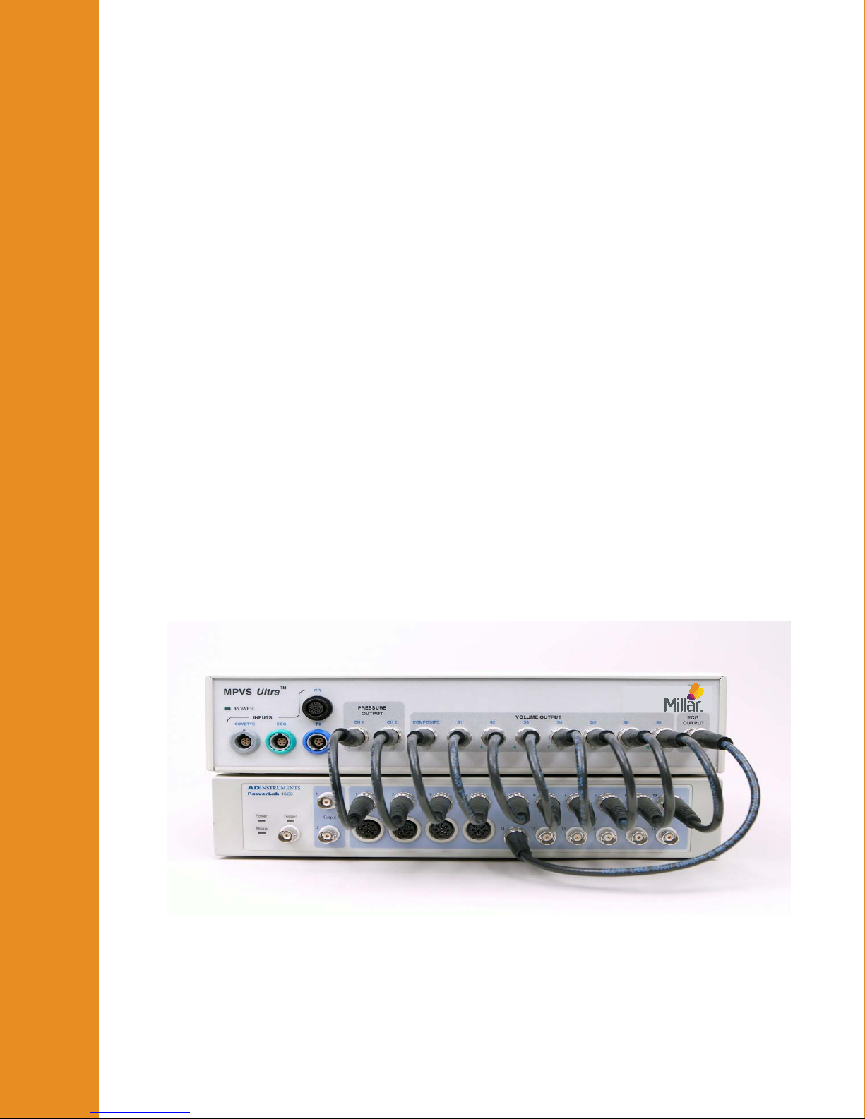
As shown below, the MPVS Ultra connects easily to the ADInstruments PowerLab16/30
using the MPVS Ultra – PowerLab cable pack. The cable pack is a set of thirteen BNC-toBNC cables specifically sized for connecting these two systems. Ten 9-inch cables are
included for connecting the first ten channels on the MPVS Ultra to the first ten channels
of the PowerLab system. A 1-foot cable is included to connect the ECG output to channel
11 of the PowerLab system. Two 3-foot cables are included for connecting the Cuvette
Output and Cuvette Temperature signals to the PowerLab system.
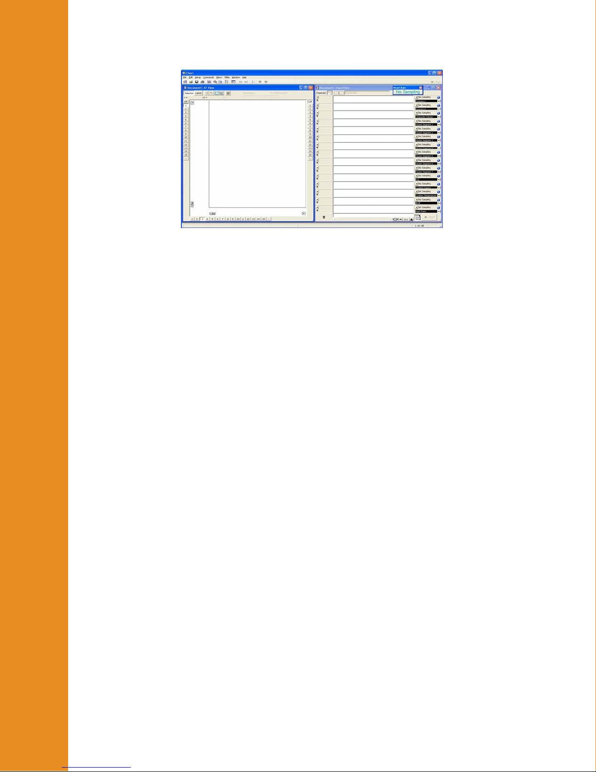
The PVAN Ultra analysis software CD also includes an ADI Chart interface file that will
save setup time by providing an interface to record data. A shortcut to the file MPVS
Ultra Interface.adiset will be installed on your Desktop during a normal installation of
the Control Interface. There will also be a shortcut in the Millar branch of the Start menu.
The settings file itself will be installed in the same directory as the Control Interface.
M.I. P/N 004-2163 Rev. C
6
Page 7
Gettin
g
Started
Note that other ADI PowerLab hardware can be used instead of a PowerLab 16/30.
Contact Millar to verify compatibility.
Tips for better performance
Steps can be taken to reduce signal noise. While the system meets CE requirements to
withstand EMI (electromagnetic interference), noisy equipment such as lamps, heaters, and
electrocautery equipment can add noise to the signal. The following suggestions can
improve the signal-to-noise ratio.
Cable Length
Use the shortest cables and cords that will serve the purpose. Millar offers 4-foot input
cables for users whose subjects will be located close to the hardware. BNC-to-BNC cables
are available in shorter lengths for those who can use them. See the “ADInstruments
PowerLab Setup” section for an example.
Cable Quality
Millar provides only high-quality shielded cables for input and output signals. If you
acquire or build your own cables, be sure that the shield is a high-quality braid or foil
shield. Be sure that the shield is connected to the ground pins indicated in the “Theory of
Operation” section. Users who build their own interface cables assume all responsibility
for harm, loss, or damage related to the use of such a cable.
Coiling Cables
For EMI purposes, the effective cable length will be reduced when a cable is coiled to take
up excess length.
System Grounding
Grounding the subject can be beneficial, but in some cases, the signal can be affected if the
animal is later ungrounded during the course of an experiment. If the animal is grounded,
leave it grounded throughout the procedure.
Grounding low-noise equipment, such as the MPVS Ultra, separately from high-noise
equipment is advisable. High-noise equipment includes lamps, room lights, heaters,
electrocautery (ESU/Bovie) equipment, power supplies, power cords and computers. If the
equipment has a metal chassis, try grounding the chassis directly. Do not let power cords
lie on top of signal cables. To avoid ground loops, connect the grounds of low-noise
equipment with the shortest possible connector lengths, preferably using the chassis ground
points such as the one found on the rear panel of the MPVS Ultra.
M.I. P/N 004-2163 Rev. C
7
Page 8

g
Gettin
g
Gettin
Normal Operation
After installation and the initial setup, the system is ready for use. The following sections
are intended to guide preparation for a protocol. Some assumptions are made that may
need to be modified to fit a particular user’s preferences. Specific instructions are included
in the “Detailed Operation” sections below.
Overview of a typical large animal procedure
Started
Started
1. Warm-up and calibration
Turn on the system, plug in the P-V and/or pressure transducer(s) and begin soaking them
in body-temperature saline or deionized water according to the instructions in the IFU. A
warm-up and pre-soak of 30 minutes or more is advisable. After the warm-up period,
balance the pressure signals and calibrate all channels of the system that will be used in the
procedure.
Place the cuvette under the animal or in a bath of body-temperature water to warm the
plastic. This will minimize temperature effects on the resistivity (rho) measurement.
2. Prepare the animal
3. Resistivity
Perform this step before volume signal calibration if data will be recorded in volume units.
Plug the cuvette cable into the MPVS Ultra. In the Control Interface Rho Cuvette tab,
select the appropriate settings. Perform the following with as little delay as possible: Dry
the cuvette’s well with a gauze or swab. In a heparinized syringe, draw at least 0.5cc of
blood. Fill the well. Click on Measure in the Control Interface. Additional information
will appear. Click on Load to set the displayed resistivity as the value to be used in
calibration and measurements.
4. Catheterize the subject
Monitor the data acquisition system output to determine proper placement of the
transducer. See recommended catheter placement below.
M.I. P/N 004-2163 Rev. C
8
Page 9
Gettin
g
Started
5. Alpha correction
If stroke volume comparison for alpha correction will be used, this may be done at any
point according to the protocol. If raw data will be recorded as volume units (ml or μl),
alpha calculation should be performed before the final volume calibration. Recalibrate the
volume signal channels now if alpha is used.
6. Record and export data as desired
Typical protocols may include baseline data, occlusion data, stimulus reaction data, and
saline bolus data. Smaller animals should have saline bolus maneuvers performed at the
end of the study in case the saline induces detrimental effects on the cardiovascular system.
7. Analyze the data in PVAN Ultra
If data were recorded in conductance units, PVAN will need resistivity (rho), segment
length and (if desired) alpha parameters.
Overview of a typical small animal procedure
1. Warm-up and calibration
Place the cuvette well in warm water or under the animal warming mat to warm the
plastic. This will minimize temperature effects on the resistivity measurement.
M.I. P/N 004-2163 Rev. C
9
Page 10

Gettin
g
Turn on the system, plug in the P-V and/or pressure transducer(s) and begin soaking them
according to the instructions in the IFU. A warm-up and pre-soak of 30 minutes or more is
advisable. After the warm-up period, balance the pressure signals and calibrate all
channels of the system that will be used in the procedure.
2. Resistivity
Perform this step before volume signal calibration if data will be recorded in volume units.
A representative animal is typically required due to the volume of blood removed. Plug
Started
the cuvette cable into the MPVS Ultra. In the Control Interface Rho Cuvette tab, select
the appropriate settings. Perform the following with as little delay as possible. Dry the
cuvette’s well with a gauze or swab. In a heparinized syringe, draw about 0.3cc to 0.5cc of
blood. Fill the well. Click on Measure in the Control Interface. Additional information
will appear. Click on Load to set the displayed resistivity as the value to be used in
calibration and measurements.
3. Prepare the animal
4. Catheterize the subject
Monitor the data acquisition system output to determine proper placement of the
transducer.
5. Alpha correction
If stroke volume comparison for alpha correction will be used, this may be done at any
point according to the protocol. If raw data will be recorded as volume units (μl), alpha
calculation should be performed before the final volume calibration. Recalibrate the
volume signal channel now if alpha is used.
6. Record and export data as desired
Typical protocols may include baseline data, occlusion data, stimulus reaction data, and
saline bolus data. Smaller animals should have saline bolus maneuvers performed at the
end of the study in case the saline induces detrimental effects on the cardiovascular system.
The saline bolus is often lethal for a mouse.
7. Analyze the data in PVAN Ultra
If data were recorded in conductance units, PVAN Ultra will need resistivity (rho),
segment length and (if desired) alpha parameters.
M.I. P/N 004-2163 Rev. C
10
Page 11
Detailed Operation
III. Detailed Operation
Hardware Connections
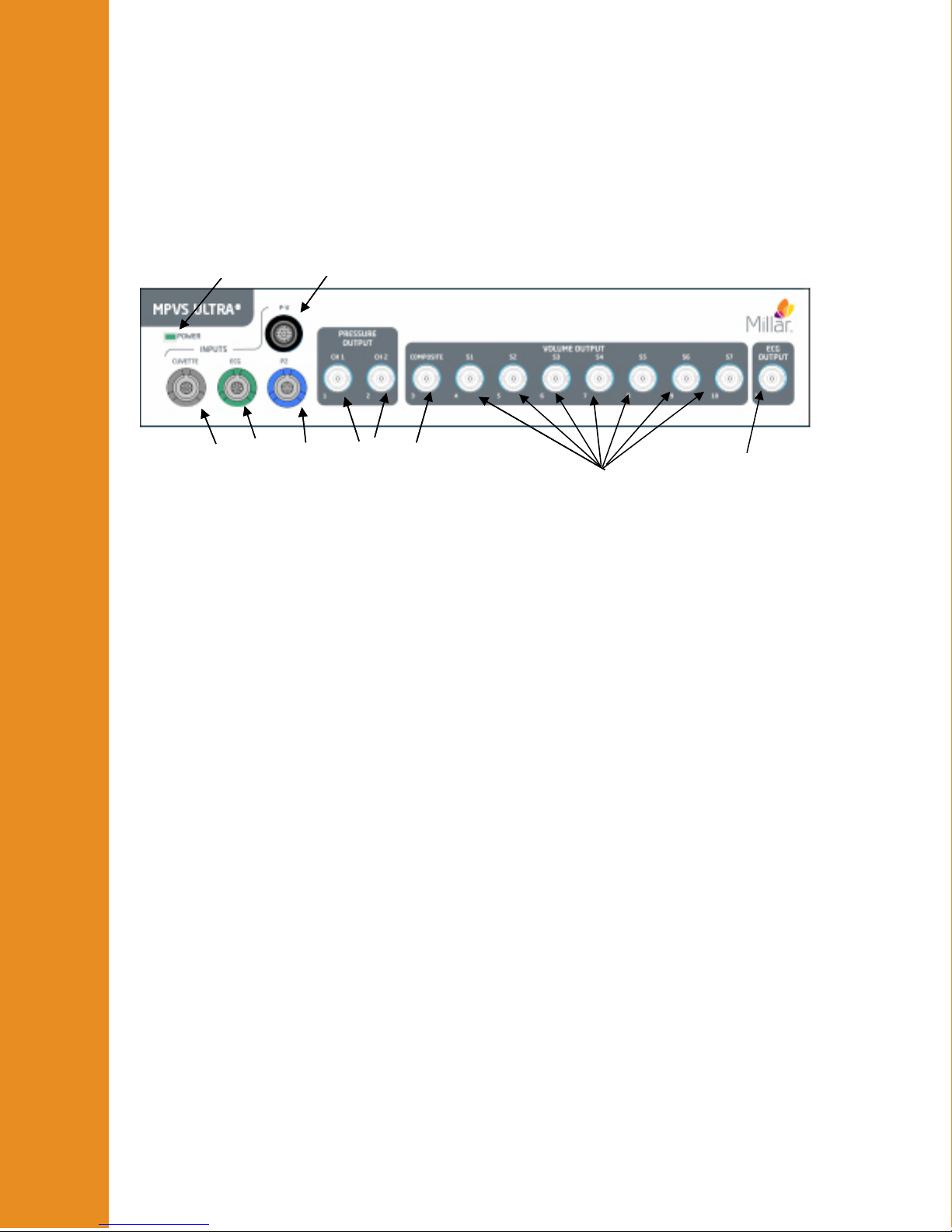
Front Panel
1
1
1. Lighted Power Indicator - The green indicator will be lit when the system is receiving
power and turned on.
2
2
3
3
4
4
5
5
6
6
7
7
8
9
2. Cuvette Input – Rho Calibration Cuvette connects to the MPVS Ultra and provides
resistivity value for volume calibration (color-coded gray)
3. ECG Input – External ECG electrodes can be connected to the MPVS Ultra (input color-
coded green) and the signal can be displayed real-time
®
4. Pressure-Only Catheter Input (P2) – A second, pressure-only, Mikro-Tip
connected to the MPVS Ultra. The input to the second pressure channel can be through
the P2 connector (color-coded blue) or the P-V connector (color-coded black).
5. Pressure-Volume Catheter Input (P-V) – The MPVS Ultra connects to all of Millar’s
Pressure-Volume catheters including the Ultra-miniature single segment P-V catheters
and the Multi-Segment P-V catheters with the appropriate cables. The system can accept
inputs from P-V transducers with one or two pressure sensors. When connecting to a
three-connector, dual-pressure P-V transducer, be sure to follow the labeling on the
connectors to ensure that the pressure sensor inputs are not swapped.
6. Analog Pressure Outputs - The MPVS Ultra provides analog output for both pressure
channels at individual BNC connectors. The pressure signals (P1 and P2) are scaled to
1V/100mmHg.
7. Analog Composite Volume Output – The MPVS Ultra provides an analog composite
volume channel that outputs the analog sum of the individual volume segments. This
signal is useful for viewing real-time P-V loops in the data acquisition software. The
volume signal compliance can be altered with the gain adjust function in the MPVS Ultra
Control Interface.
catheter can be
8. Analog Volume Segment Outputs – The MPVS Ultra provides an analog output for a
maximum of seven volume segments which can be displayed in real-time on a computer
through the data acquisition system. The pressure-volume analysis software PVAN Ultra
will use these individual segments. The volume signal compliance can be altered with
the gain adjust function in the MPVS Ultra Control Interface.
M.I. P/N 004-2163 Rev. C
11
Page 12
Detailed Operation
9. Analog ECG Output – The MPVS Ultra provides an analog ECG channel that will output
the ECG measured with the catheter or with an external transducer.
Rear Panel
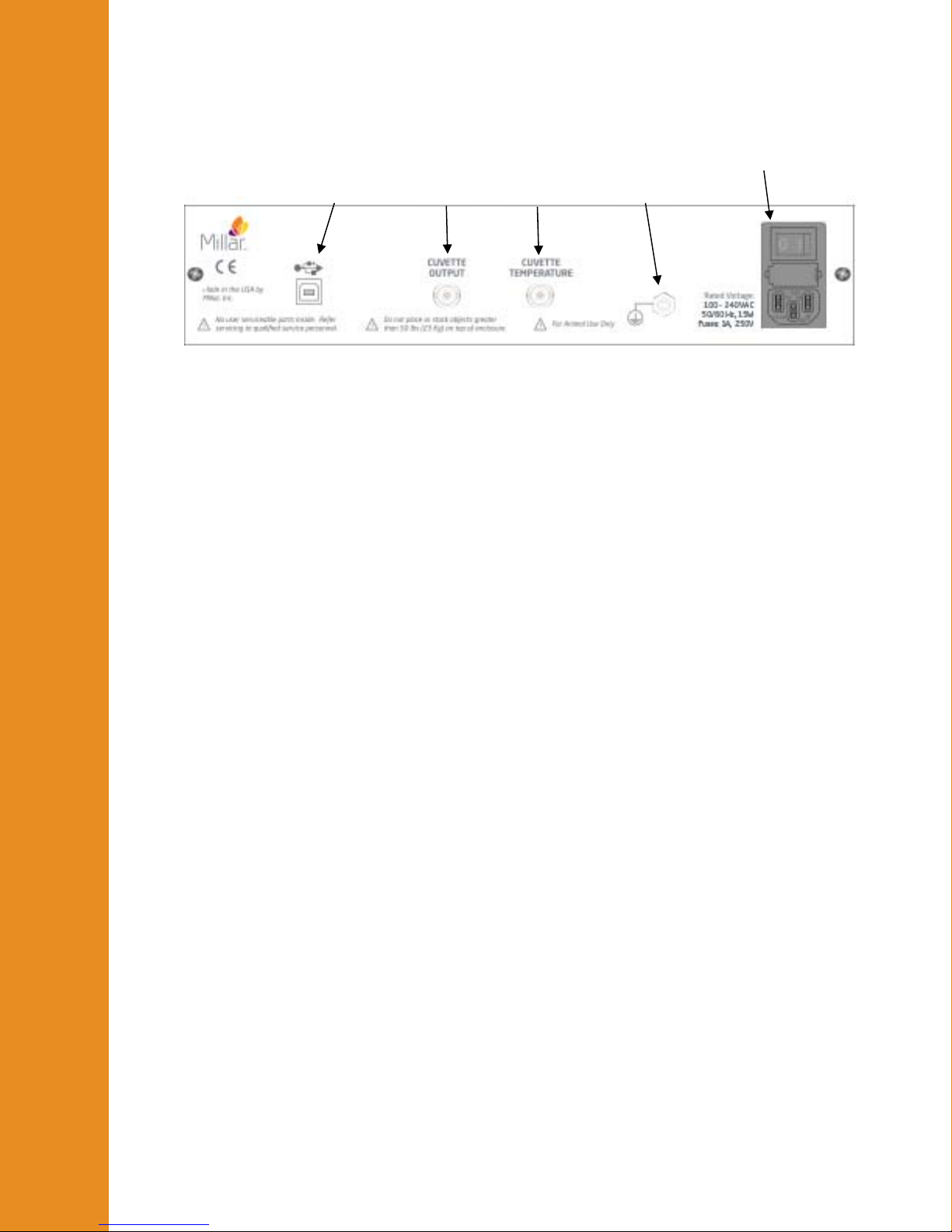
1. USB Control – The MPVS Ultra system is controlled by the MPVS Ultra Control
Interface software through a USB connection. The system requires a computer
with USB (v1.1) or later. A USB cable is included with the system. Connect the
MPVS Ultra hardware to your computer before turning the computer on. The first
time that a computer is connected to an MPVS Ultra system, software drivers will
be installed; this installation won’t be necessary after the first installation.
1
2
3
4
5
2. Cuvette Output – The system is designed to provide a numerical value for the
resistivity measurement using the MPVS Ultra Control Interface. The analog
voltage signal of this measurement is provided on this connection, but users
typically will not use this signal. There is no straightforward conversion between
voltage and resistivity.
3. Cuvette Temperature – The system is designed to provide a numerical value for the
blood temperature using the MPVS Ultra Control Interface so that the user can
choose to correct the resistivity measurement for temperature dependency. The
analog voltage signal of this measurement is provided on this connection, but users
typically will not use this signal in connection with blood sample temperature.
With proper calibration, a user can choose use the temperature input pins on the
front panel Cuvette input (see previous photo) to measure temperature with a
thermodilution catheter. See “Theory of Operation –Temperature Measurement”
for instructions. See “Recommended Accessories” for ordering information for
the particular connector.
4. Equipotential Point (Ground) – The equipotential point or ground post provides a
point at which the user can connect to the system’s analog ground point. The
equipotential point is connected to the ground wire of the power cord. Connecting
the equipotential point to a common ground point with other equipment and
possibly the subject may help reduce noise if signal noise is a problem. Note that
the subject connections and the rho cuvette connections (all analog signal inputs)
are isolated and therefore are not grounded to this point.
5. Universal Power – The system can be powered by 90VAC at 60Hz or 264VAC at
50 Hz. Use the power cord included with your system in North America or
Europe. Power cords for other regions are available through your distributor or
through the source listed in “Recommended Accessories”. See the Technical
Specifications section for more specific information about the power requirements.
M.I. P/N 004-2163 Rev. C
12
Page 13

Detailed Operation
MPVS Ultra Control Interface
The Control Interface software allows the user to manage catheter configuration, calibrate
all signals, and measure resistivity through an intuitive graphical user interface.
Single-Segment Mode
The MPVS Ultra is shipped from the manufacturer in Single Segment Mode. This mode
only allows for the use of PV catheters with one volume segment such as the PVR-1045
and the SPR-838. A keycode must be entered in order to use the system in Multi-Segment
Mode.
Registration
The Registration Menu allows the user to upgrade a MPVS Ultra Single Segment to the full
Multi-Segment mode. If the user initially purchased the MPVS Ultra with Multi-Segment
capabilities, a keycode will be supplied with the shipment. For information about upgrading
a MPVS Ultra Single Segment unit for use with Multi-Segment PV catheters, please
contact Customer Service.
Export
The Export menu allows the user to save the Catheter Configuration settings for later use in
the PVAN Ultra analysis software. Saving the settings under a recognizable name and
recording the name in the study notes allows the user to load the settings into PVAN Ultra
without having to enter the setting manually.
Catheter Configuration tab
The Catheter Configuration screen allows the user to configure the hardware for
operation with a specific catheter model by setting the appropriate electrode configuration,
choosing the field configuration, excitation current and gain setting. The user can also enter
blood resistivity and alpha for volume calibration.
M.I. P/N 004-2163 Rev. C
13
Page 14
Detailed Operation
(new screenshot)
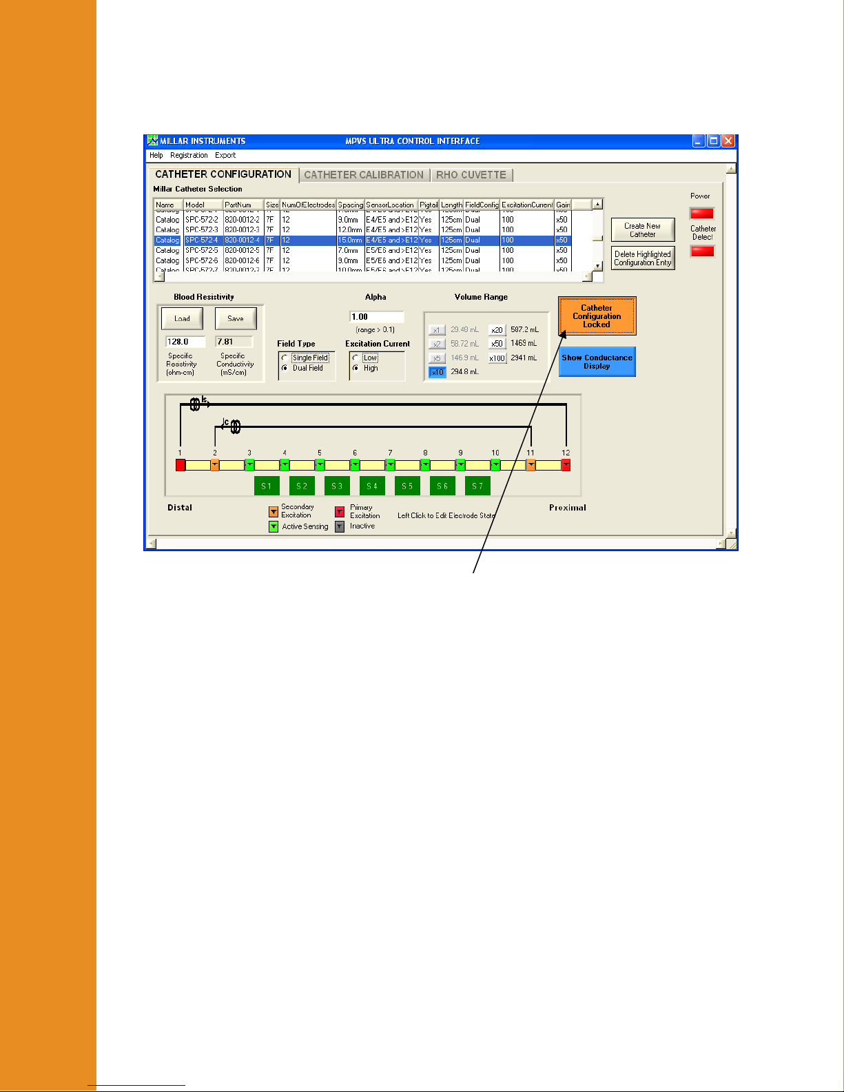
Catheter Configuration Locked/Unlocked
This button unlocks and locks the controls on the Catheter Configuration tab in order to
prevent inadvertent changes to the system settings which would affect the
conductance/volume signal as it is being recorded. Click the button once to unlock the
settings.
The catheter configuration must be unlocked before any of the controls on the Catheter
Configuration tab can be adjusted.
The locking feature has a timeout feature which will relock the features after sixty seconds
have passed with no configuration changes.
By default, the catheter configuration used when the program is opened will be the same as
the configuration when the program was last closed.
Millar Catheter Selection
The Millar Catheter Selection table allows the user to load both standard and custom
catheter configurations. This allows the user to configure the hardware for immediate use
based on a known catheter model.
The Millar Catheter Selection table contains several descriptive fields described below.
The table can be sorted by clicking on the desired field name. Click once to sort in
ascending order. Click again to sort in descending order.
M.I. P/N 004-2163 Rev. C
14
Page 15

Detailed Operation
Name – The Name field is set to Catalog for standard catheter configurations. Users can
select their own name when either editing a catalog catheter or creating their own catheter.
Model Number – This refers to the Millar model number of the catheter. Catheters
modified using the Create New Catheter option retain the model from the catheter from
which they were created. Custom catheters contain a user defined model.
Part Number – This refers to the Millar part number.
Size – Refers to the French size of the catheter. 3F = 1 mm diameter.
ElectrodeNumber – Refers to the number of electrodes on the catheter.
Spacing – Refers to the spacing between sensing electrodes. This spacing is used by the
software when calculating volume from Baan’s equation for calibrating in units of volume
(μl or ml).
Sensor – Describes the location of the pressure sensor(s). The pressure sensor is located
between the listed electrodes. If a pressure sensor is located proximal to all electrodes, its
location will be described as “>E12” or “>E4” as appropriate.
Length – Refers to the length of the catheter from connector to tip.
FieldConfig – Refers to the excitation field configuration of the catheter – single field or
dual field.
ExcitationCurrent – Refers to the excitation current set for this catheter configuration.
SegAmplifierGain – Refers to the chosen gain setting for this catheter configuration.
Blood Resistivity
This feature controls the resistivity used in Baan’s equation for calculating the volume
displayed on the gain and calibration controls within the Control Interface. The values can
also be saved for use in PVAN Ultra. The MPVS Ultra system can measure resistivity
using the rho cuvette (see information regarding the Rho Cuvette tab) or the user can
enter a value for resistivity. Resistivity is used by the software when calculating volume
from Baan’s equation for calibrating in units of volume (μl or ml).
Click Load to recall information used in a previous study. Click Save to save the present
value for later use. The interface allows the user to name the entry.
Unlock the catheter configuration and click Load to load settings from a previous study or
the latest measurement from the rho cuvette.
Alpha (α)
Alpha is an electric field homogeneity factor that allows a user to scale volume
measurements to match independent measurements. This is typically done to make the
stroke volume measurement given by Baan’s equation and the conductance method match
the stroke volume measurement given by thermodilution, ultrasound or flow-probe
measurements. Alpha is saved along with the present blood resistivity value and is used by
the software when calculating volume from Baan’s equation for calibrating in units of
volume (μl or ml).
Graphical Electrode Configuration Control
When a catheter configuration is selected in the Millar Catheter Selection table, the
display in the control will adjust to match the configuration. The user can then adjust the
M.I. P/N 004-2163 Rev. C
15
Page 16

Detailed Operation
electrode configuration; for example, choosing to use fewer electrodes when measuring a
ventricle whose length does not justify the use of all available electrodes.
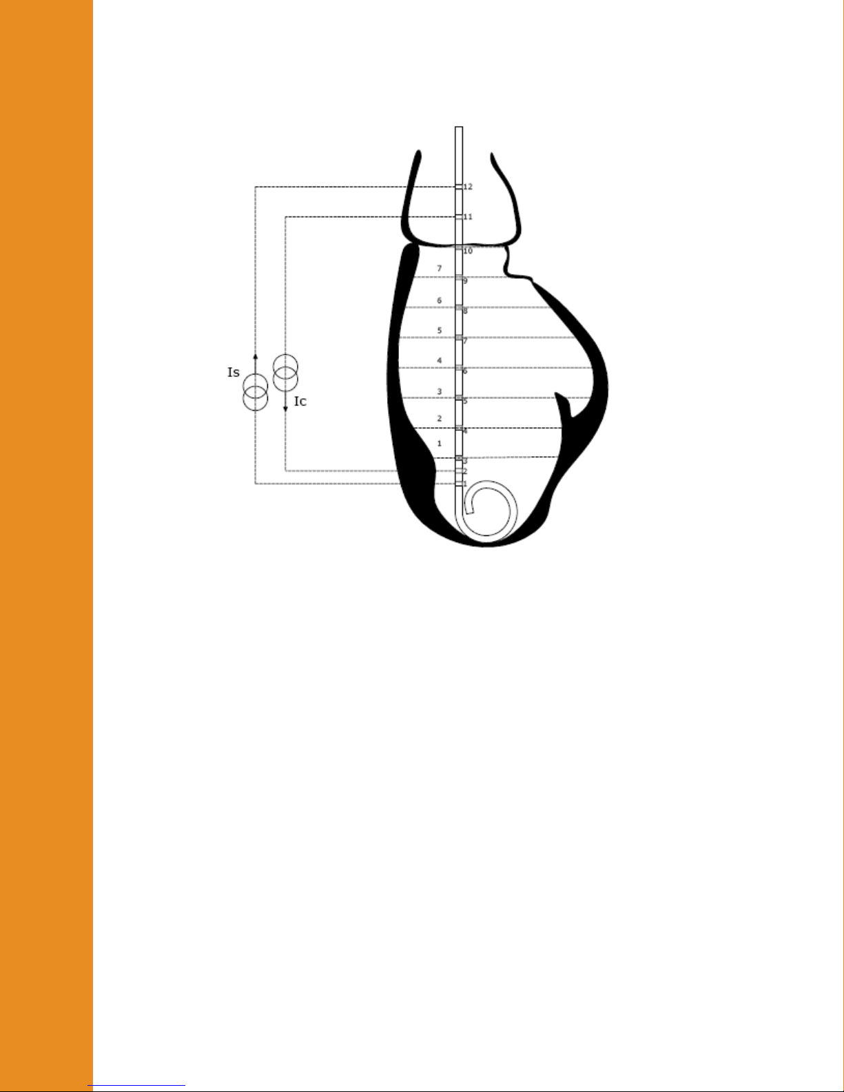
There are four electrode states which can be chosen by the user to configure the catheter to
his specification.
1. Inactive – Inactive electrodes are grayed out. These electrodes are not used in generating
or sensing the electric field.
2. Active Sensing – Active sensing electrodes are green. An active sensing electrode
represents one edge of a volume sensing segment.
3. Primary Proximal – Primary electrodes are red. The primary proximal electrode
designates the most proximal edge of the primary electric field. The user can choose to
use any of electrodes 4 – 12 as the primary proximal electrode.
4. Secondary Proximal – Secondary electrodes are orange. The secondary proximal
electrode designates the most proximal edge of the secondary electric field. The user can
choose to use any of electrodes 5 – 11 as the secondary proximal electrode.
Configurations are limited according to the following rules:
1. Electrode 1 must be the primary distal excitation electrode. Only electrode 2 may be
used for secondary distal excitation (but electrode 2 may be used for sensing in a single-
field configuration). See the next section for a description of Field Type.
2. There can be no adjacent inactive electrodes.
3. All active sensing electrodes must be between excitation electrodes.
4. There must be at least two active sensing electrodes.
The green boxes below the catheter graphic label the location of the segments that are
being measured. The labels (S1-S7) correspond to the labels above the connectors on the
front panel of the hardware. When an inactive electrode is located between two active
electrodes, two segments are combined into one segment and two green boxes will have
the same label. The output signal for the resulting double-length segment will be
effectively the sum of the two segments. Be sure to account for this in processing the data.
The system can be configured for one to seven segments.
Field Type
The system can measure conductance with either single field or dual field excitation. This
control determines which is used in the present study. The field configuration of catalog
models is related to the electrode layout. Dual field catheters will have three closely
spaced electrodes at one end (usually the tip) whereas single field catheters have evenly
spaced electrodes. 12-electrode catheters are dual field catheters. Almost any catheter can
be operated in dual- or single-field, but a minimum of six electrodes is required for dualfield excitation. See “Theory of Operation – Dual Field Excitation” for more information.
The graphical electrode configuration control will reflect the selected field type. The
primary and secondary fields’ excitation currents are illustrated when Dual Field is
selected. Only the primary field’s excitation current is illustrated when Single Field is
selected.
Dual Field mode can only be used with high excitation current.
M.I. P/N 004-2163 Rev. C
16
Page 17

Detailed Operation
Excitation Current
Catalog models use 20μA for small animal models and 100μA for large animal models.
Either excitation level can be used, regardless of catheter model, but the user is responsible
for determining how much current can be used for smaller animals. Changing the current
setting may require a change in gain setting. If the current is decreased, a larger gain
setting may be required.
Segment Gain-Conductance Range/Segment Gain-Volume Range
The system is capable of measuring the conductance within the ventricle of animals
ranging in size from transgenic mice to domestic livestock. Use the Segment Gain
Conductance (Volume)
while keeping the system output from saturating. Choose Conductance Display (blue) or
Volume Display (orange) by clicking on the button to the right of the Segment Gain
Conductance (Volume)
gains (e.g., x1) while larger animals will measured with higher gains (e.g., x100). Note the
conductance or volume values to the right of the gain select buttons. The value shown is
the maximum signal that should be measured across all active electrode segments. This
setting affects the available calibration settings on the Catheter Calibration tab.
Range control to make full use of the system’s output range
Range control. Smaller animals will be measured with lower
Show Volume Display/Show Conductance Display
This control will determine whether the guidance values in the Segment Gain
Conductance (Volume) Range control are volume values or conductance values.
Create New Catheter
Use this button to create a new entry in the Millar Catheter Selection table. This is
particularly useful if you regularly use a catheter in a configuration that doesn’t match its
“catalog” entry in the table. Users who purchase a Special model or any other model not
listed on the table may need to add their catheter’s configuration. The Name field can be
used as a descriptive term such as the serial number of the catheter or the experimental
group to which it applies (e.g. “50kg canine”).
Before clicking on the Create New Catheter
similar to the new configuration as possible. Select the appropriate Field Type,
Excitation Current, and Segment Gain Conductance (Volume) Range. Set the
electrode settings on the graphical representation as appropriate. Click Create New
Catheter and fill in the appropriate information. Click OK.
Delete Highlighted Configuration Entry
Use this button to delete non-catalog model catheters from the Millar Catheter Selection
table. Catalog models cannot be deleted.
Power
This indicator will be green when the MPVS Ultra hardware is turned on and red when the
hardware is turned off.
button, select an existing model that is
Catheter Detect
This indicator will be green when the catheter is successfully passing the primary
excitation current through the selected electrodes. If the indicator is red, there may be a
problem with the cable or the catheter. Check all connections and see the troubleshooting
section. Current will not pass through the catheter when the catheter is not in a conductive
M.I. P/N 004-2163 Rev. C
17
Page 18
Detailed Operation
fluid such as blood or saline, so the catheter must be in a conductive fluid to use this
feature.
Catheter Calibration Tab
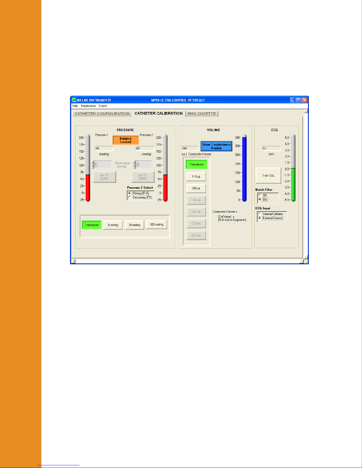
The Catheter Calibration screen allows the user to electronically calibrate the pressure,
volume, and ECG signals.
Pressure
Balance Locked/Unlocked Button
Use the Balance Locked/Unlocked button to unlock the balance controls.
The button automatically locks after 60 seconds of inactivity within the balance controls
interface.
Pressure 1/Pressure 2
The Pressure 1 and Pressure 2 scales graphically display the currently measured
pressure from −25 mmHg to 200 mmHg.
This number is also numerically displayed. The calculation of the pressure value is based
upon the system’s scale of 1V/100mmHg. The system provides 5V excitation to
transducers assumed to have a sensitivity of 5μV/V/mmHg. (See “Theory of Operation –
Strain Gauge Pressure Transducers.”) The system is designed to use Millar Mikro-Tip
pressure transducers with 1000 ohms input impedance and 1000 ohms output impedance.
All Millar Mikro-Tip pressure transducers are factory-calibrated to meet these standards.
®
M.I. P/N 004-2163 Rev. C
18
Page 19

Detailed Operation
Offset Value (mmHg)
The user can manually adjust the pressure offset of each pressure channel. This is useful
when an artificial offset is introduced into a system and requires correction.
To adjust the pressure offset, unlock the balance controls and use the offset arrows to
manually adjust the offset up or down. The user can also type the desired value directly
into the Offset Value fields. As noted in the procedural descriptions above and in the
transducer IFUs, it is advisable to do this balance adjustment after soaking the catheter for
30 minutes. Ideally, the pressure sensor should be just below the surface of warm (body
temperature) water and shielded from ambient light. See the troubleshooting section for
tips on proper balancing techniques.
The range of the offset is −250 mmHg to 250 mmHg.
The balance control does not affect the electronic calibration outputs (0mmHg, 25mmHg,
and 100mmHg) described below.
Auto Zero
The user can quickly auto zero each pressure channel by applying a zero reference pressure
to the catheter and then clicking Auto Zero under the desired channel. This sets the
applied pressure as zero.
Pressure 2 Select
The MPVS Ultra provides two amplifiers for use with a pressure transducer.
Pressure 1 is always set to the P-V input connector on the MPVS Ultra front panel. This
will typically be the pressure sensor located in the middle of the conductance electrodes.
Pressure 2 Select allows the user to specify which input is used for the secondary
pressure channel.
Primary (P-V) sets the second pressure input to the P-V input connector on the MPVS
Ultra front panel. This is used when the user is using a dual sensor pressure volume
catheter such as the SPR-562-1.
Secondary (P2) sets the second pressure input to the P2 input connector on the MPVS
Ultra front panel. This is used when the user is using a separate single sensor pressure
catheter.
Pressure Monitor and Calibration
Transducer – When the Transducer button is activated the system will read inputs from
the pressure sensors. The Transducer button must be activated to view pressure
waveforms.
0 mmHg – When the 0 mmHg button is activated, the MPVS Ultra will output a zero volt
signal to both pressure outputs.
25 mmHg – When the 25 mmHg button is activated, the MPVS Ultra will output a 0.25
V signal to both pressure outputs.
100 mmHg – When the 100 mmHg button is activated, the MPVS Ultra will output a 1.0
V signal to both pressure outputs.
M.I. P/N 004-2163 Rev. C
19
Page 20

Detailed Operation
Volume
Display Conductance/Volume Units
Use this button to change the display to conductance or volume units as desired. This
button does not affect the output voltage.
Measured Volume
This display indicates the current composite volume as measured by the MPVS Ultra. The
value displayed is based upon an analog summation of all active segments. This analog
sum is the COMPOSITE output on the front panel.
The blue or orange scale is a graphical representation of the composite volume signal.
When the user opts to view units of volume (μl or ml), the calculation of this value takes
into account segment length, rho and alpha chosen on the Catheter Configuration tab.
The output shown in the MPVS Ultra Control interface does not account for the volume
attributed to parallel conductance of the myocardium. If desired, this correction can be
made in the PVAN Ultra software or the user’s acquisition software.
Transducer and Electronic Calibration Buttons
The active button is green. To measure a volume signal from the catheter, click the
Transducer button.
In order to calibrate the data acquisition system from voltage to volume or conductance
units, the system has six internal sets of resistors that are used as inputs of known
conductance. Only two to three buttons are available at any given gain range. (Available
buttons are beige; others are gray.) The available selections are designed to span the
expected segmental conductance inputs for typical animals ranging from mice to domestic
livestock. The gain setting on the Catheter Configuration tab controls the available input
range in order to maximize the use of the available voltage output range. The indicated
values on the buttons are the conductance or volume to be output by each segment, not the
composite total.
The values indicated on the calibration buttons change according to the present
configuration. When volume units are displayed, Baan’s equation is used, so the present
values of alpha, rho, and segment length are used, as noted in Measured Volume above.
Since the values on the buttons represent the per-segment conductance or volume, be sure
to multiply by the number of active segments when entering the calibration value for the
Composite Volume channel. The Composite Volume or Composite Conductance value is
displayed by the software when one of the calibration buttons is pressed.
ECG Calibration
The ECG Calibration interface allows the user to generate a calibration signal for the ECG
output, control the source of the signal, and enable or disable the notch filter.
Current Value
The numerical readout displays the current ECG signal measured by the MPVS Ultra.
ECG Scale
The ECG Scale graphically displays the current ECG signal measured by the MPVS Ultra.
M.I. P/N 004-2163 Rev. C
20
Page 21
Detailed Operation
1 mV Cal
This button outputs a one second 1 mV cal signal. The signal can be used to calibrate the
user’s data acquisition system or monitor. Note that since the ECG circuit has a high-pass
filter to eliminate DC offset, the output signal will appear as an initial upward pulse and
then a downward pulse. This is an ECG circuit’s response to a square wave.
The ECG output is scaled at 2V / 1 mV.
Notch Filter
The MPVS Ultra contains a built-in notch filter on the ECG circuit to remove 50Hz and
60Hz noise. To turn this filter on, select “On” and to turn it off, select “Off”.
ECG Input
The ECG Input allows the user to choose the source of the ECG input signal.
The MPVS Ultra can record an internal ECG signal from the electrodes on the P-V
catheter. To record this signal select Internal Catheter.
The MPVS Ultra can also be used as a bioamplifier for an external ECG source. To
choose this option, select External Source. The input for this signal is the ECG connector
on the front panel of the hardware.
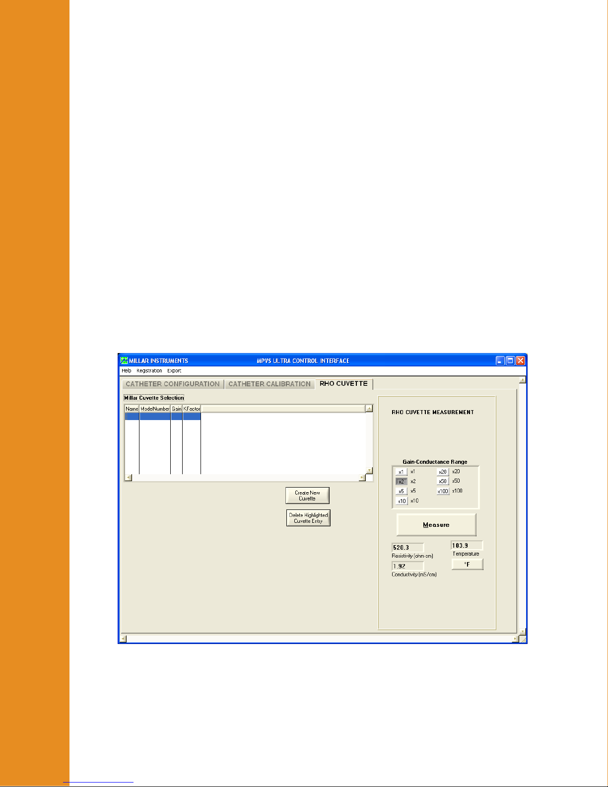
Rho Cuvette Tab
Millar Cuvette Selection
This table contains the specifications for the catalog cuvettes built by Millar. Different
entries can be added with different gains and K factors. The gain will typically be x2.
M.I. P/N 004-2163 Rev. C
21
Page 22

Detailed Operation
K Factor
The K factor is a calibration value that is specific to your system. While all of the parts of
your MPVS Ultra system are made with precision, slight variations are inherent in the
design. The K factor is used to reduce the error in the resistivity reading. Your system is
delivered with a K factor. The K factor is entered when you create a new entry in the
Millar Cuvette Selection table. It cannot be changed from the main interface shown
above. The software will not accept a K factor value below 0.100.
Create New Cuvette
Use this feature to create an entry in the Millar Cuvette Selection table. This will allow
you to use the K factor that is specific to your system. Before clicking the Create New
Cuvette button, be sure that the gain in the Gain-Conductance Range field is correct.
(Unless a need arises to do otherwise, use a gain of x1.) After clicking the Create New
Cuvette button, enter a name for the cuvette configuration (for example, you may choose to
use the lot number written on the cable). Enter the K factor for your system. (The gain
cannot be changed in this view.) Click OK, then click on the new entry in the Millar
Cuvette Selection table.
Delete Highlighted Cuvette Entry
Unwanted entries can be deleted from the table if desired. The catalog model entry cannot
be deleted.
Gain Conductance Range
The MPVS Ultra provides seven gain settings which serve to optimize the accuracy of the
resistivity reading for a particular fluid. Fluids used in most experiments will be best
measured with a gain of x2.
Export
Click the Export button to place the displayed resistivity value into the Blood Resistivity
field on the Catheter Configuration tab. This will automatically unlock the catheter
configuration.
Millar recommends saving the file with a descriptive name to ease later identification.
Measuring the resistivity of a blood sample
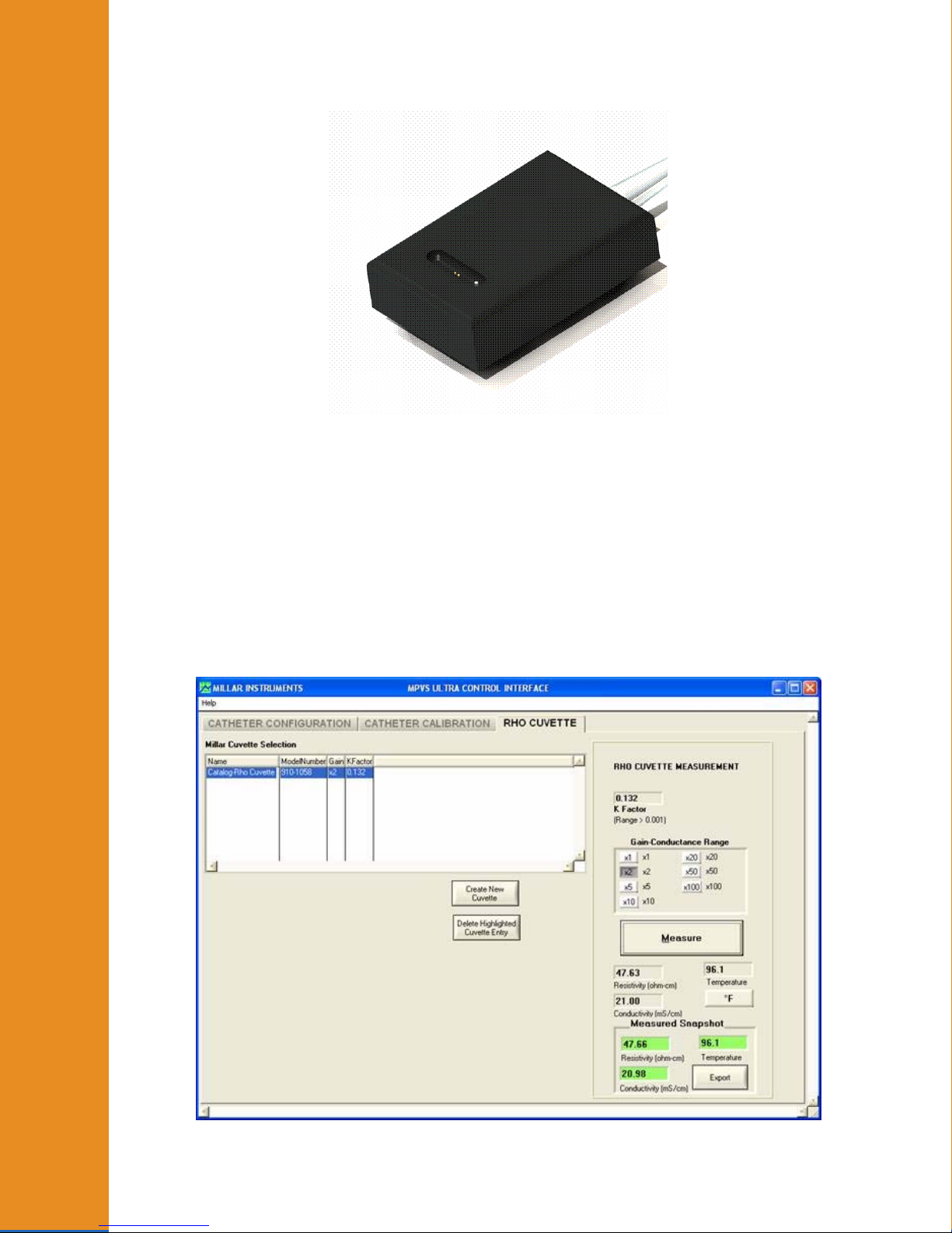
1. Connect the cuvette (shown below) to the MPVS Ultra‘s Cuvette input. Warm the
cuvette to body temperature in order to minimize errors due to the change in the blood’s
temperature. The cuvette can be placed under the animal or a warming mat or it can be
submerged in warm water. Do not submerge the cable and connector.
M.I. P/N 004-2163 Rev. C
22
Page 23
Detailed Operation
Detailed Operation
2. In the Millar Cuvette Selection field, select the appropriate configuration. By default,
the software will use the configuration that was used most recently. The configuration
includes both the gain and the K factor.
3. Select the desired units for temperature measurement (°F/°C).
4. With as little delay as possible, do steps 4-6. Place the cuvette on a flat surface and dry
the well with a gauze or swab.
5. In a heparinized syringe, draw about 3cc to 5cc of blood. Place the tip of the needle at
the bottom of the well and inject the blood into the well. Ideally, the surface of the blood
should be level with the top surface of the cuvette.
6. Click on Measure in the Control Interface. The Measured Snapshot field will appear.
M.I. P/N 004-2163 Rev. C
23
Page 24

Detailed Operation
Detailed Operation
Detailed Operation
7. Click on Load to set the displayed resistivity as the value to be used in calibration and
measurements. The loaded resistivity value affects the displayed reading and calibration
values when displaying volume units. The resistivity value is not temperature corrected;
the user is responsible for deciding whether and how to correct for temperature.
8. Save this value to your computer using a descriptive name so that the file can be
identified at a later time (i.e., Sheep_1623_3-01-07).
9. Properly dispose of the blood sample and thoroughly clean the cuvette.
Cleaning the Cuvette
The cuvette should always be emptied and cleaned immediately after use to prevent blood
from clotting within the cuvette.
Procedure for cleaning the cuvette
1. Properly dispose of the used blood sample.
2. Rinse the cuvette with warm water for several minutes.
3. Soak the cuvette in a beaker of enzymatic cleaner for 15 – 30 minutes.
4. Rinse the cuvette with warm water for several minutes.
5. Dry the cuvette completely using either a Kim Wipe or an air dryer.
6. Store the cuvette in its container.
Conductivity, Resistivity, Temperature
The Resistivity, Conductivity and Temperature fields located directly under the
Measure button dynamically display the measured values from the attached cuvette. Use
the °F/°C button to select the displayed units of temperature.
M.I. P/N 004-2163 Rev. C
24
Page 25

Theor
y
IV. Theory of Operation
The Conductance Method
of Operation
Single Segment Measurement
Researchers are able to estimate left-ventricular volume changes via the conductance
method using the tiny electrodes built into the catheter tip.
A small constant-amplitude AC current is sent out through the distal electrode (E1) to the
proximal electrode (E4). The current flow creates an electric field within the ventricle.
The voltage potentials (differences) between the two inner sensing electrodes (E2 and E3)
are measured as the heart expands and contracts and the volume of the left ventricular
blood pool changes. The operational theory of the impedance/conductance method for
estimating left ventricular volume changes can be simplified in terms of Ohm's Law.
Ohm's Law
V = IR
G = 1 , therefore R = 1 x
R G
V = I , therefore G = I x
G V
Volume
V
____________________
V = voltage potential between E2 and E3
I = constant current
G = I x
C = conductance (the inverse of resistance)
R = resistance of the left ventricular blood pool
During systole, the heart pumps blood out of the left ventricle and the resistance of the
blood pool increases; therefore, the voltage potential between the inner two electrodes (E2
and E3) also increases.
During diastole, the left ventricle is filling with blood and the resistance of the blood pool
decreases; therefore, the voltage potential between the inner two electrodes (E2 and E3)
also decreases.
Systole = R ↑ V ↑ G ↓ and Volume ↓
Diastole = R ↓ V ↓ G ↑ and Volume ↑
A good analogy is to think of the blood-filled left ventricle as a wire that changes size
during the cardiac cycle.
M.I. P/N 004-2163 Rev. C
25
Page 26

y
p
Theor
y
Theor
A thick gauge wire (large diameter) will have a low resistance and a low voltage drop across
it (diastole). The wire contains more volume because it has a larger diameter.
A thin gauge wire (small diameter) will have a high resistance and a high voltage drop across
it (systole). The wire contains less volume because it has a smaller diameter.
Multi-Segment vs. Single-Segment
of Operation
of O
eration
Millar’s multi-segment P-V catheters measure volume using the conductance technique
described above. Unlike the single-segment catheter, a multi-segment catheter measures
conductance over several electrode segments. The system then sums individual segments’
signals to generate a total volume signal over the length of the catheter. In the MPVS
Ultra system this summation is performed in PVAN Ultra when the user records data for
individual segments. The composite volume channel is an analog sum of the voltages in
the active channels.
Baan’s Equation
The basis for calculating volume from conductance is Baan’s equation. The general
equation for volume measurement is given to be:
Volume = 1 ρ L
α bb
2
(G – Gp)
where alpha (α) is the volume calibration factor, rho (ρ) is the resistivity of the blood, L is
the segment length, G is the conductance and Gp is the parallel conductance of surrounding
structure.
In a multi-segment measurement, G is actually a summation of the segmental conductance
measurements.
Dual Field Excitation
The dual field method sends the primary excitation current through a selected primary
excitation electrode (E5 through E11) located at the proximal end of the measurement area
and through primary excitation electrode (E1) located at the distal end of the measurement
area to generate an electrical field within the heart. In addition to the primary excitation
current, a secondary excitation current of opposite polarity is sent through the next
electrode, located distal to the selected primary excitation electrode at the proximal end of
the measurement area and secondary excitation electrode (E2) at the distal end of the
measurement area. This secondary excitation current creates a second electrical field
which serves to expand the primary field to create a more uniform electrical field over the
length of the measurement area. The change in conductance as the blood pool changes is
then measured across each electrode segment and then summed for a total volume signal in
the same manner as the single field configuration.
Dual field catheters can be quickly identified by the group of three closely spaced
electrodes at either the proximal or distal end of the measurement area.
Field lines and equipotential planes
Ideally, when measuring the resistance of a uniform (homogeneous) material, the paths of
the electrons are straight from one end of the sample to the other. Equipotential planes,
which are perpendicular to the current flow, would be flat surfaces. The result would be a
current density that is uniform throughout the sample, which means that every portion of
the sample affects the measurement equally. This requires the current generated in the
M.I. P/N 004-2163 Rev. C
26
Page 27

y
p
Theor
y
Theor
sample to be injected evenly across the ends of the sample. However, the conductance
catheter method requires the use of two very small areas to inject the current. Thus, the
current density is much higher at these two points than at points half way between, where
the electrons are able to spread out. The current density will also be higher near the axis of
the current flow (the catheter) than in regions farther away since the electric field tends to
decrease with the cube of the distance.
In a single field configuration, the path of the current through the blood is not straight.
of Operation
of O
eration
When graphed together, the electrons’ paths resemble the shape of an American football,
where the ends are narrow (the electrons must all pass through the electrodes) and the
central portion is expanded (the like charges of the electrodes cause them to repel each
other and spread out). Equipotential planes, drawn perpendicular to the electrical flow, are
not flat, except at a point half way between the excitation electrodes. Equipotential planes
closer to the electrodes tend to bow outward, away from the center plane. This effect is
more pronounced farther from the catheter, so measurements of smaller diameter volumes
can approximate a uniform field.
In a dual field configuration, the secondary current is injected to change the shape of the
electrical field so that it is more uniform. The polarity of the secondary current is the
opposite of that of the primary current and the amplitude is 30% of the primary current.
This straightens the equipotential lines and makes the electric field more uniform,
optimizing the electrical field to allow a more uniform measurement of volume in larger
hearts.
Resistivity – Rho Cuvette
Resistivity is a material property whereas resistance (and therefore conductance) is a
property of a sample or a structure. When measuring the conductance of the blood in the
ventricle, the reading is based on the electrical current passing through blood, a material
whose resistivity can change with temperature, hematocrit, and a number of other
parameters. Resistivity is used in Baan’s equation to relate conductance of the structure
(the blood in the ventricle) to the volume of the structure.
The MPVS Ultra rho cuvette measures resistivity using Baan’s equation, but in a form
where the equation has been solved for resistivity. The volume of blood in the cuvette is
known – it is that of a cylinder whose diameter is that of the well and whose length is the
distance between the voltage sensing electrodes. The current passed through the sample is
known since it is precisely calibrated during the manufacturing process. The voltage is
readily measured by the MPVS Ultra hardware. The resistivity can then be computed from
these known and measured values. (α is assumed to be 1.)
Effects of Temperature
The resistivity of blood is temperature dependent. The MPVS Ultra system does not adjust
the reading to correct for temperature. Instead, the rho cuvette measures the temperature of
the blood and the resistivity of the blood at the same time. (These are the values reported
in the Control Interface.) The user can correct for temperature if desired. Peer-reviewed
literature indicates that the resistivity of the blood varies by about 2% per degree C within
a few degrees of body temperature. This relationship is not linear, so the user should
attempt to make the measurement as quickly as possible after blood is drawn from the
animal. It is advisable to keep the rho cuvette well at approximately body temperature
before taking the measurement so that the well will not contribute to the cooling of the
blood sample.
M.I. P/N 004-2163 Rev. C
27
Page 28

Theor
y
Resistivity – Dip Cuvette
The dip cuvette method used in the MPVS-300, MPVS-400, and MPCU-200 ARIA
pressure-volume measurement systems was used as a way of relating measurements to
volume in a more empirical manner. The dip cuvette contains wells into which blood is
injected. The catheter is then dipped into each well so that the system is reading from a
known volume in a material assumed to have the same resistivity as that in the subject’s
ventricle. Relating the resulting readings to the known volumes (typically through a linear
of Operation
regression) allows the user to calibrate measured voltages to volumes. This method is less
direct than that employed by the MPVS Ultra system and is not practical for use with
multi-segment P-V catheters.
IECG vs. ECG
The MPVS Ultra can measure the ECG signal from the PV (catheter) input or the ECG
input. When the system measures ECG from the PV catheter, the signal is an internal
ECG, or IECG. Since the electrodes are in the ventricle, the source of the R wave, the R
wave will be much larger than the other aspects of the ECG signal. While this may not
provide some of the information for a detailed ECG analysis, the signal-to-noise ratio will
be reduced and the signal will be ideal for timing in PVAN Ultra calculations. The input
to the IECG signal is the electrodes that are presently in use for the primary excitation
field. This ensures that the spacing between the electrodes will be as wide as possible for a
maximal signal.
When the system measures the ECG through the ECG connector, the signal will resemble a
normal ECG signal.
Since the hardware only has one ECG amplifier circuit, the MPVS Ultra can only measure
one signal at a time.
Strain Gauge Pressure Sensors and Catheter Tip
Transducers
Strain Gauge Pressure Sensor
Millar Mikro-Tip pressure transducers use a microscopic pressure sensor embedded in the
tip of a catheter to measure pressure directly at the source. The design offers superior size,
accuracy, and frequency response. The pressure sensor contains a pair of strain-gauges on
a very thin diaphragm. These gauges are resistors whose resistance changes as they are
stretched. The gauges are stretched when pressure exerted on the diaphragm makes it
bend. These resistors are in turn wired into a Wheatstone bridge circuit. When the
resistors change resistance in response to pressure changes, the output voltage of the
Wheatstone bridge changes. The voltage output of the circuit is amplified by the MPVS
Ultra, whose output is factory calibrated to a 1V output for an input pressure of 100mmHg.
M.I. P/N 004-2163 Rev. C
28
Page 29

Theor
y
Care of Ultra-Miniature P-V Catheters
Proper Handling is Critical to Maximizing the Use-Life of Millar's Ultra-miniature PV Catheters. Refer to the Troubleshooting, System Maintenance, and Specifications
section of this document for important information.
Additional guidelines
of Operation
Temperature Measurement
The system was designed assuming that the input to the temperature measurement circuit
will be a thermistor with a standard J curve and a resistance of 10kohms at 25degreesC.
This is the type of temperature sensor that is used in the rho cuvette. It is possible to use
the temperature measurement circuit in the MPVS Ultra to measure temperature from
another source. For example, a thermodilution catheter with an appropriate thermistor can
be connected to the system. The output of the temperature measurement circuit is available
on the rear panel of the MPVS Ultra. The user is responsible for calibrating the
relationship between voltage and temperature.
When making a custom cable to connect a temperature measurement device to the Cuvette
input, use the diagram below.
2
3
4
1
Pins 5 and 6 are the inputs to the thermistor. Do not connect to pins 1, 2, 3, or 4 since
doing so may damage the resistivity measurement circuit. Pin 7 may be used to ground the
shield of the cable. It is very important to note that all four front-panel inputs are isolated
from the voltage outputs, power input, USB input and equipotential point. However, these
four inputs are not isolated from each other. When using accessories not designed or
provided by Millar, the user assumes all responsibility for damage, harm, or loss resulting
from the use of these accessories.
7
6
5
Conductance, Conductivity, Resistance, Resistivity
It is important to note the differences and relationships among conductance, conductivity,
resistance and resistivity.
Resistivity and conductivity are properties of materials and are subject to the condition of
the material when it is measured. Just as with metals, the conductivity and resistivity of
blood is temperature dependent. The resistivity value used in volume calculation should
ideally be measured in blood that is representative of the study groups. At a minimum, be
sure to take species into account as resistivity varies between species. There is a noticeable
difference in the resistivity of blood and that of muscle. Size and shape do not affect
resistivity and conductivity.
M.I. P/N 004-2163 Rev. C
29
Page 30

Theor
y
Conductance and resistance are properties of a sample or a structure. They will be affected
by the resistivity (or conductivity) of the materials in the sample. Size and shape of a
sample have a strong bearing on resistance and conductance.
Conductivity is the multiplicative inverse of resistivity.
Conductance is the multiplicative inverse of resistance. G = 1/R
Conductance and conductivity relate to how well a structure or material conducts electrical
of Operation
current.
Resistance and resistivity relate to how strongly a structure or material resists the flow of
electrical current.
Further Reading
The Millar, Inc. web site, millar.com, lists published papers.
M.I. P/N 004-2163 Rev. C
30
Page 31
g
Theor
y
Troubleshootin
V. Troubleshooting, System Maintenance and
Specifications
Refer to the MPVS Ultra training CD (001-1058) for more information.
of Operation
Each catheter is delivered with Instructions for Use, complete with care and cleaning
instructions.
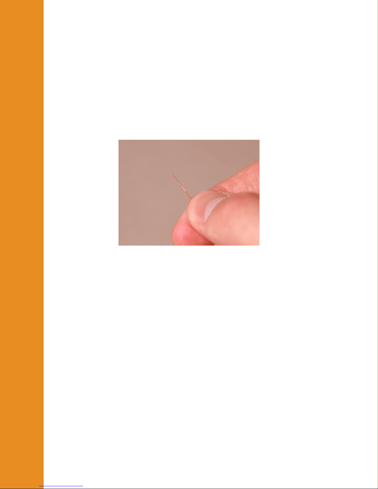
Proper Handling is Critical to Maximizing the Use-Life of Millar's Ultra-miniature PV Catheters
The Mikro-Tip® catheter is a robust yet delicate precision instrument.
Presoak the catheter tip for at least 30 minutes prior to use in saline or distilled water
maintained at body temperature. Only soak the catheter tip. Do not submerge the catheter’s
electrical connectors, as doing so will damage the sensitive electronics housed inside!
The presoak helps prepare the pressure sensor diaphragm for the "wet" biological
environment. Presoaking the catheter tip in body-temperature fluid also helps prevent
pressure signal drift and negative pressure recordings. The presoak can be done by gently
inserting the catheter tip into a beaker, dish, or through the tip of a syringe.
Do not, under any circumstances
Bend
Kink
Fold
Cut
Pinch
Crush
®
the Mikro-Tip
These actions could severely damage the catheter or render the catheter unusable and result
in costly repair or replacement charges!
M.I. P/N 004-2163 Rev. C
catheter, especially around the sensor/electrode area!
31
Page 32
Theor
y
Additional guidelines
Use of the Mikro-Tip
familiar with, and have been trained to perform, the catheterization procedures for
which the device is intended
The Mikro-Tip
etc.) prior to each use.
of Operation
Do not grip the Mikro-Tip
anywhere near the sensor/electrode area.
Always grip the Mikro-Tip
(E4). Never grip the catheter between the electrodes or between the electrodes and
the pressure sensor case.
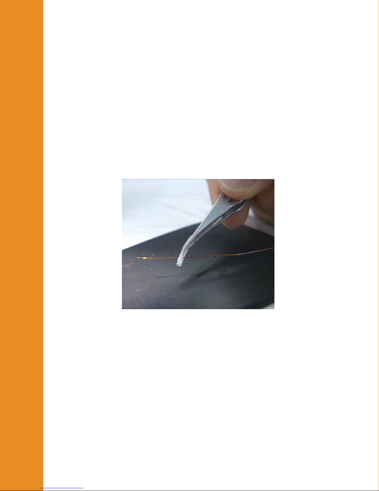
When using metal forceps or tweezers to grip the Mikro-Tip
some soft tubing over the tips of the metal instrument to cushion the interface
between the instrument and the catheter body, as shown in the photo.
®
®
P-V catheter should be restricted to specialists who are
P-V catheter should be inspected for damage (cracking, kinks,
®
P-V catheter with forceps, tweezers, or fingers
®
P-V catheter proximal to the sensor/electrode area
®
P-V catheter, slip
Always be mindful of the location of the catheter tip.
Do not set heavy objects or metal instruments on top of the Mikro-Tip
catheter.
Do not tighten sutures over the sensor/electrode area on the Mikro-Tip
catheter.
When using the carotid artery approach to insert the Mikro-Tip
the left ventricle, advance the sensor/electrode area completely beyond the
proximal suture before tightening the suture.
When using the carotid artery approach to insert the Mikro-Tip
the left ventricle, take care not to damage the catheter with the tips of any forceps
or tweezers used to grip the artery when inserting the catheter.
M.I. P/N 004-2163 Rev. C
32
®
®
®
P-V
®
P-V
P-V catheter into
P-V catheter into
Page 33

Theor
y
When using the open chest approach to insert the Mikro-Tip
the left ventricle, do not push the catheter tip directly through the left ventricular
wall. First, make an entry hole in the ventricular apex with a needle, and then
insert the catheter through the hole.
Never apply excessive force when inserting the Mikro-Tip
catheter may incur damage, and could puncture the left ventricular wall or
of Operation
damage the aortic valve.
If resistance is encountered while inserting the Mikro-Tip
back slightly and then try advancing again.
When removing the Mikro-Tip
the proximal suture before pulling the catheter out, to ensure the pressure sensor
or electrodes do not catch on the suture and lift or tear away from the catheter.
The Mikro-Tip
“Cleaning” section).
The pressure sensor element on the Mikro-Tip
electrostatic discharge. Do not touch the sensor element while the catheter is
disconnected from the monitoring equipment.
The Mikro-Tip
after each use to determine its condition. Carefully examine the catheter for cuts,
kinks, or creases.
®
P-V catheter should be cleaned immediately after each use (see
®
P-V catheter should be thoroughly inspected under magnification
®
P-V catheter through the carotid artery, loosen
®
P-V catheter into
®
P-V catheter. The
®
P-V catheter, pull
®
P-V catheter is sensitive to
The active surface of the sensor and electrodes should be examined for film that
has not been removed by cleaning. Any film may cause short-term baseline drift,
and should be removed. Remove film by thoroughly soaking in Terg-A-Zyme®,
followed by persistent and gentle wiping along the sensor or electrodes with a
moist tissue, gauze, or cotton-tipped swab. The connectors should undergo visual
inspection for corrosion or bad contacts.
Hardware
The enclosure can be wiped with isopropyl alcohol (70%) on a damp cloth. Do not allow
any liquids to enter the enclosure.
When connecting and disconnecting the system, check the following:
Be sure that the enclosure is not cracked and that all of the screws are installed in the
bottom and rear panels.
Be sure that none of the cables (including the power cord) are frayed, cut, or cracked. All
cables should connect firmly to the system.
All except for the USB and power cords lock in place when properly connected.
Be sure that none of the cables or cords are bent sharply as this may damage the internal
wires.
M.I. P/N 004-2163 Rev. C
33
Page 34

Theor
y
If necessary, the fuses can be replaced by removing the drawer on the rear panel. It is
located between the power switch and the power input connector. Use the fuse type
indicated on the rear panel.
Other than the fuses, the MPVS Ultra has no user-serviceable parts. Do not open the
enclosure or any cable connectors. Contact Millar or your distributor for service.
of Operation
Cables
The cables can be wiped with isopropyl alcohol (70%).
Do not submerge the cables or cords.
When connecting and disconnecting the cables and cords:
Be sure that none of the cables (including the power cord) are frayed, cut, or cracked. All
cables should connect firmly to the system.
All except for the USB and power cords lock in place when properly connected.
Be sure that none of the cables or cords is bent sharply as this may damage the internal
wires.
M.I. P/N 004-2163 Rev. C
34
Page 35
Technical Specifications
Technical Specifications
Pressure Transducer Characteristics
Specification Value
Transducer Sensitivity 5 µV/V/mmHg, nominal
Bridge Excitation Load
Resistance
Transducer Bridge Excitation 5.0 VDC, nominal
Signal Input Resistance 50 mega-ohms, nominal
Input connector for system Five-pin Redel or ODU
Pressure Outputs
1000 ohms, nominal
350 ohms, minimum
Specification Value
Sensitivity 1 V/100 mmHg, nominal.
Accuracy Error Band 0 – 200mmHg: <±1 mmHg or 1 % of reading,
whichever is greater
201 – 300mmHg: < 1.5 % of reading
Frequency Response DC to 400 Hz (-3 dB)
Noise <0.3 mmHg peak-to-peak
Balance Adjustment Range ±140 mmHg, nominal
Pressure Standby-Calibration Mode
Specification Value
Zero Offset <±1 mmHg
Calibration Steps 0, 25, and 100 mmHg
Calibration Accuracy <± 0.5 mmHg
M.I. P/N 004-2163 Rev. C
35
Page 36
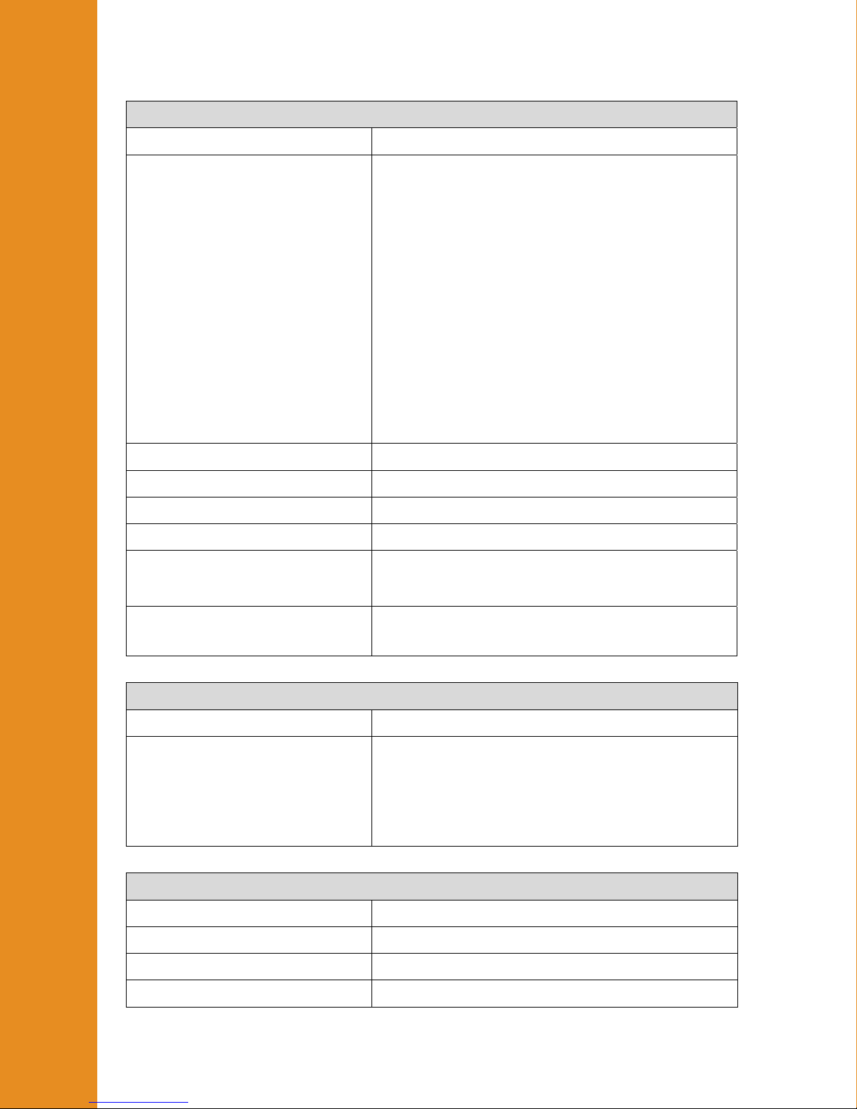
Technical Specifications
Volume/Conductance Outputs
Specification Value
Sensitivity Seven gain settings with the following maximal
conductance inputs for single field (SF) and dual
field (DF) configuration at 20 or 100 uA
excitation:
Gain SF-100 SF-20 DF-100 Units
1 - 3.33 - mS/segment
2 - 6.67 - mS/segment
5 - 16.7 - mS/segment
10 167 33.4 117 mS/segment
20 333 66.6 233 mS/segment
50 833 167 583 mS/segment
100 1667 333 1167 mS/segment
Frequency Response 400 Hz
Output Resistance 1690 ohms, nominal
Output Voltage ±10 VDC
Noise ≤ 75mVPP
Input Connector 27-pin Alden Pulse-Lok®
Pulse-Lok is a registered trademark of Amphenol Alden
Products Company, Inc.
Output Connectors BNC connector
Composite, S1, S2, S3, S4, S5, S6, S7
Volume/Conductance Standby-Calibration Mode
Specification Value
Calibration Verification Steps
Single Field excitation mode: 1.14mS, 2.78mS,
10.1mS, 33.2mS, 133mS and 476mS.
Dual Field excitation mode: 1.18mS, 2.82mS,
10.1mS, 33.2mS, 133mS and 476mS.
Inputs are available at appropriate gain ranges.
Temperature Measurement
Specification Value
Range 24 – 43 °C (75 – 110 °F)
Accuracy of analog output ±0.36°F (±0.2°C) over 32.2-40.6˚C (90-105˚F)
Input type J curve thermistor, 10k-ohm at 25°C, beta = 3890
M.I. P/N 004-2163 Rev. C
36
Page 37
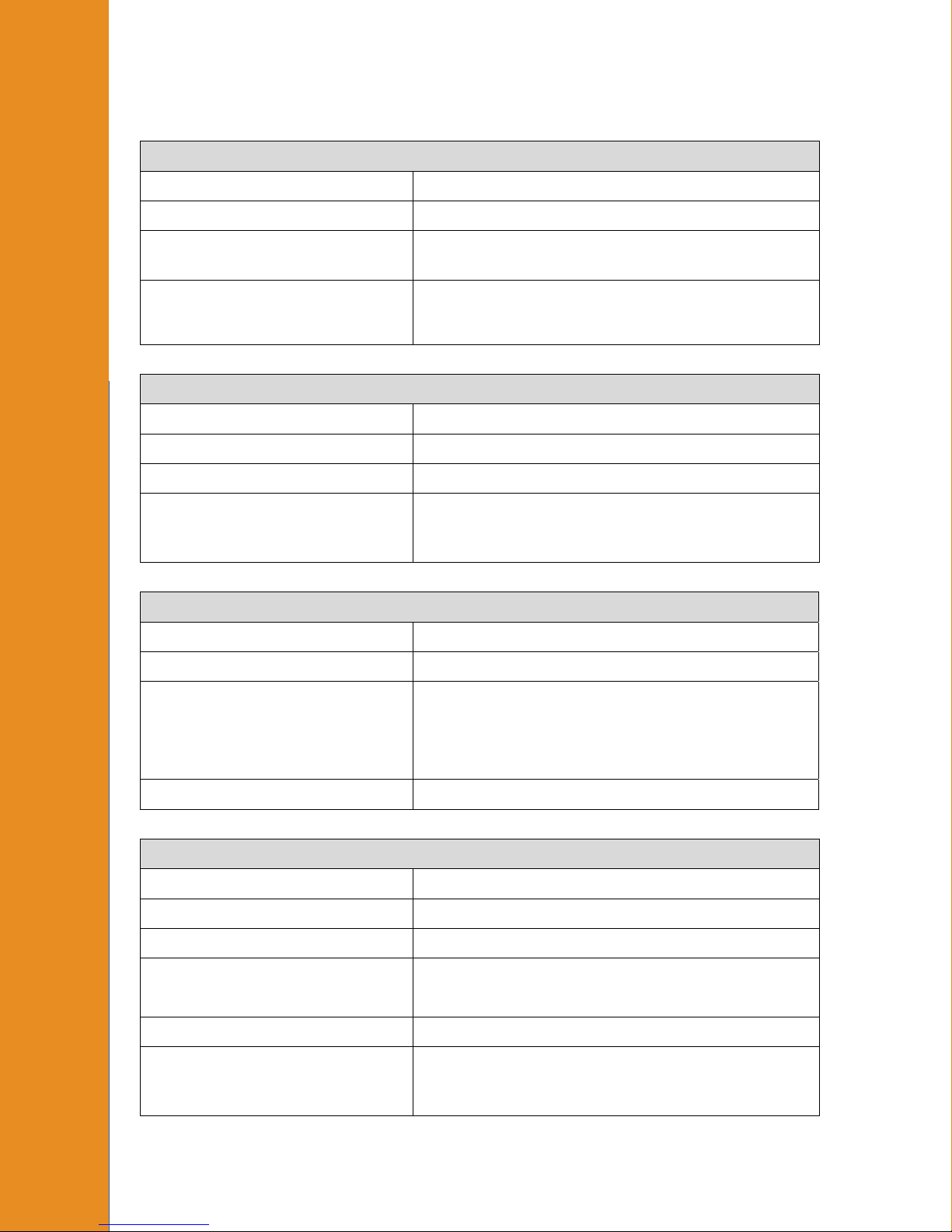
n
Technical Specifications
ECG
Specification Value
Gain 2000 X
Frequency Response Band pass filter from 0.5Hz to 35Hz (-3dB attenuation)
Software enabled/disabled 60Hz notch filter
Source Software selectable between external leads connected
through front panel receptacle and primary conductance
excitation electrodes (for IECG).
Power
Technical Specificatio
Specification Value
Input (Universal) 100 – 240VAC, 50 – 60 Hz, 15W
Connector type EN60320/C13
Ground terminal resistance to
power cord ground pin, 7-ft
cord
Enclosure
Specification Value
Ingress protection IP-20
Dimensions 12 3/8” x 11 3/4” x 2 7/8” (width x length x
Weight 5.6 pounds (2.54kg)
Environmental Conditions
Specification Value
Location Indoor Use
<1 ohm
height)
31.4cm x 29.7cm x 7.3cm (width x length x
height)
Altitude Up to 2000m
Operating Temperature 10 – 40 °C (50 – 104 °F)*
Storage Temperature -20 – 70 °C (-4 – 158 °F)
Mains Supply Voltage
Fluctuations
M.I. P/N 004-2163 Rev. C
*
±3% over 1mS to 1000mS range
Power supply voltages may vary by up to 10% of
the nominal voltage (110V
Transient overvoltages are allowable.
37
or 220VAC).
AC
Page 38
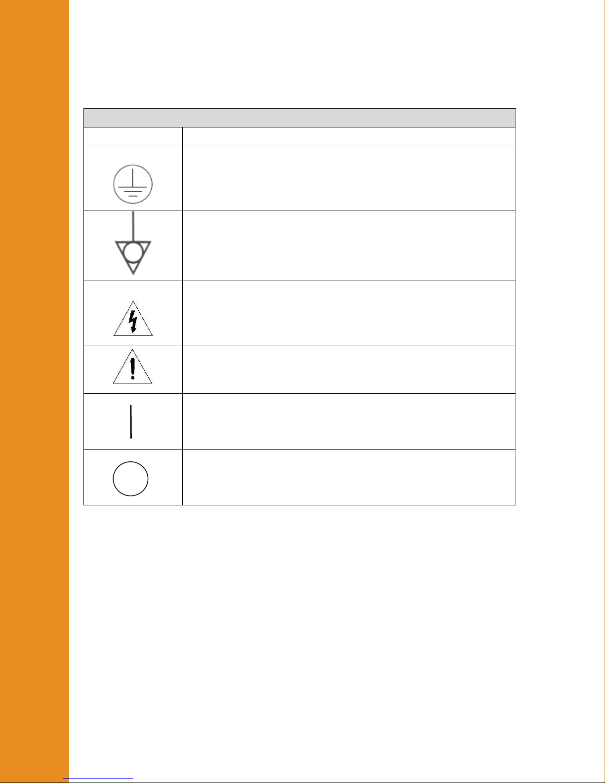
Technical Specifications
Explanation of Symbols
Symbol Explanation
Protective Conductor Terminal (This terminal is connected to earth
ground through the power cord.)
Equipotential point (The output circuitry of the MPVS Ultra uses this
terminal as a ground point. This point is also connected to earth ground.)
Caution, risk of electric shock. (Do not open the MPVS Ultra enclosure.
There are high voltages inside. There are no user-serviceable parts
inside.)
Caution, risk of danger, see note.
On (System power)
Off (System power)
Technical Support
Technical Support
The Purchaser is entitled to free technical support for any Millar product. Millar’s technical
support staff can provide help and advice concerning installation, operation, particular uses
and problems with Millar products. Millar’s technical support staff will not provide
experimental protocols or procedural instructions for conducting experiments. However,
information of this type may be provided in the supplied product documentation, or be
found on the Millar web site.
Technical support can be provided to the Purchaser via the following options:
Phone 1-800-669-2343 or 832-667-7000
8:00AM – 5:00PM, Central Time, M-F
M.I. P/N 004-2163 Rev. C
38
Page 39

Technical Specifications
Technical Specifications Technical Specifications
Fax 713-714-8497
24 hours a day, 7 days a week
Email [email protected]
24 hours a day, 7 days a week
Web millar.com
Mail Millar, Inc.
6001-A Gulf Freeway
Houston, Texas 77023
USA
On-site installation and training for Millar products can be provided for an additional
charge. Please contact Millar’s customer service department for further details.
Recommended accessories
Power cords
Requirements
The system has been qualified with power cords whose maximum length is 2.5m (8′ 2″).
The input connector on the MPVS Ultra rear panel is a standard EN60320/C14, so a power
cord with a standard EN60320/C13 connector is required.
Millar supplied cords
Millar can provide replacements for the cords that were shipped with the system. Use
these part numbers when ordering
850-5105 North American cord with NEMA 5-15 plug, 2m (6′ 7″) long
850-5118 European cord with CEE (7)VII plug, 2.5m long
850-5117 North American hospital grade power cord, 2.5m (8′ 2″) long (not included with
the system, but available as a replacement component)
Distributor
Your distributor may be able to provide you with a power cord.
Manufacturers
Feller www.feller-at.com
Interpower Corporation www.interpower.com
Fuses
The system requires two fuses which can be replaced by removing the tray in the power
input module on the rear panel of the system. The parts are available from Millar.
Reference Millar part number 241-0180.
The fuse requirements are 1A, 250V.
Fuses are also available from most electronics distributors. An example is Bel Fuse, Inc.,
part number 5ST1-R, www.belfuse.com
M.I. P/N 004-2163 Rev. C
39
Page 40

Technical Specifications
Cables and Connectors
ECG cable – unterminated
Millar offers ECG cables with tinned-wire terminations so that a user can attach any style
of ECG connector desired.
850-5123 10-foot ECG cable with tinned-wire terminations
ECG input connector
Users may construct their own ECG cable. The required connector is available from the
manufacturer and some distributors.
Strain Relief Lemo/Redel part number 1B.054,DV
Connector Lemo/Redel part number PAG.M08Gl.AC65GZ
Equipotential cable
The ground post on the rear panel is compliant with the DIN 42801 standard. MultiContact offers products that are designed to connect to this type of connector.
www.multicontact.com
BNC Cables
Standard BNC cables are required for connecting to the outputs of the MPVS Ultra. BNC
cable quality is important for ensuring clean signals, so be sure to use coax cables with a
braided copper shield. Millar offers high-quality BNC cables in three lengths. Most
electronics distributors offer BNC cables as well.
249-7118 3-foot BNC cable
850-5126 1-foot BNC cable
850-5125 9-inch BNC cable
880-0169 MPVS Ultra cable pack, 10-foot
880-0170 MPVS Ultra cable pack, 4-foot
880-0171 BNC cable pack, 13 × 3-foot
880-0172 BNC cable pack, PowerLab User
Connector for temperature input
In order to connect to the Cuvette input for temperature recording, use one of the following
connectors. They are available from the manufacturer and some electronics distributors.
ODU, www.odu-usa.com or www.odu.de
Connector, part number S21M07-P07MFG0-657S
Strain relief, part number 701023207965050
Redel, www.lemo.com
M.I. P/N 004-2163 Rev. C
40
Page 41

Technical Specifications
Connector, part number PAGM07GLAC65GZ
Strain relief, part number GMA.1B.054.DG
Rho Cuvette
910-1060 Rho Cuvette
M.I. P/N 004-2163 Rev. C
41
Page 42

Warrant
y
Warranty
Warranty Agreement
Extent
This Agreement is between Millar, Inc. (“Millar”) and the purchaser (“the Purchaser”) of
any Millar product – software, hardware, catheters, cables and/or accessories – and covers
all obligations and liabilities on the part of Millar, the Purchaser, and other users of the
product. The purchaser (or any user) accepts the terms of this Agreement by using the
product. Any changes to this Agreement must be recorded in writing and have Millar’s and
the Purchaser’s consent.
Copyright and Trademarks
Millar develops proprietary sensor technology, catheters, signal conditioning hardware and
computer software including Mikro-Tip® catheter transducers and PVAN software. All
Millar software, hardware, and documentation are protected by copyright, and may not be
reproduced or copied in any way, nor may products be derived from or based on it. Millar
retains the exclusive ownership of the trademarks represented by its company name, logo,
and product names.
Responsibilities
The Purchaser and any others using any Millar product agree to use it in a sensible manner
for purposes for which it is suited, and agree to take responsibility for their actions and the
results of their actions.
If problems arise with a Millar product, Millar will make all reasonable efforts to fix them.
This service may incur a charge, depending on the nature of the problem, and is subject to
the other conditions cited in this Agreement.
General Limitations
Millar products are produced to high standards, and should perform substantially as
described in the supplied documentation. There is a limited hardware warranty, and
technical support is provided for all products.
Nevertheless, since Millar products could be affected by external factors (for instance, an
environment filled with electronic noise or the computer system on which the products are
run), absolute performance and reliability cannot be guaranteed. No warranty, either
express or implied or statutory; other than contained in this Agreement, is made in respect
to Millar products. The Purchaser therefore assumes all risks as to the performance and
reliability of the products, and the results gained using them. Millar is not responsible for
any problems with the computer system not directly related to Millar products.
Millar neither assumes nor authorizes any person to assume on its behalf any liability in
connection with the sale, installation, service, or use of its products. Millar shall not be
held responsible for special, consequential, or punitive damages of any kind arising out of
sale, installation, service, or use of its products.
Millar Limited Hardware Warranty
Millar warrants that at the time of sale to the original Purchaser, the MPVS Ultra series
hardware shall be free from defects in materials and workmanship for a period of one (1)
year from its date of shipment to the original purchaser. If there is such a defect, Millar
will, at no charge and at its option, either repair or replace the equipment as appropriate.
M.I. P/N 004-2163 Rev. C
42
Page 43

Warrant
y
y
Millar’s limited warranty does not cover damage to the product from alterations, misuse,
abuse, negligence, or accident.
There are no user-serviceable parts inside the cabinet and the Purchaser should make no
attempts to service the hardware. There is no need for the Purchaser to open the cabinet for
inspection or maintenance, and doing so within the warranty period will void the warranty.
This warranty applies only to the hardware specified in this document and used under
normal operating conditions and within specification. It does not cover hardware modified
in anyway, subjected to unusual physical, electrical, or environmental stress, used with
incorrectly wired or substandard connectors or cables, or with the original identification
marks altered.
Warrant
Since factors beyond Millar’s control may directly affect the product and the results
obtained from its use, Millar or its agents or employees shall not be liable for any
incidental or consequential loss, damage, or expense arising directly or indirectly from the
use of this product.
The user shall determine the suitability for use of these devices for research purposes only.
Therefore, the user accepts these devices subject to all the terms hereof. Furthermore,
Millar does not warrant that equipment is suitable for any specific purpose, other than that
explicitly stated by Millar.
Millar hereby excludes all warranties not herein stated, whether express or implied by
operation of law or course of dealing or trade usage or otherwise, including but not limited
to any implied warranties of fitness or merchantability.
Products Supplied But Not Manufactured by Millar
Millar-supplied products of a third party manufacturer, i.e. data acquisition systems,
amplifiers, computers, monitors, and printers including associated cables, probes,
accessories, etc. are not warranted by Millar. These items are covered by the original
manufacturer’s warranties. Please contact the manufacturer directly if you encounter a
defect with a third-party product. If a fault arises, Millar will help assist in determining
which products may be the source of the problem encountered.
Note: If your problem involves computer hardware, back up data from the hard-disk
drives(s) and any other storage device(s) in the product and remove any storage media,
such as diskettes or CDs.
Warranty Service
To obtain service under the terms of this warranty, the Purchaser must notify Millar or the
nearest authorized Millar distributor of the defect before the warranty period expires. The
Purchaser must contact Millar or the nearest authorized Millar Distributor to obtain an
RMA (Returned Materials Authorization) number and an address to which the Purchaser
must ship the defective product at their own expense. The product should be packed safely
(preferably in its original packaging) and have the RMA number prominently displayed on
the return packaging, preferably beneath the address or shipping label. Millar will make all
reasonable efforts to evaluate the product and provide service as necessary within a
reasonable amount of time upon receipt of the returned product. Millar will pay the return
shipping costs in the event the product is to be sent back to the Purchaser.
Technical Support
The Purchaser is entitled to free technical support for any Millar product. Millar’s technical
support staff can provide help and advice concerning installation, operation, particular
M.I. P/N 004-2163 Rev. C
43
Page 44

Warrant
y
uses, and problems with Millar products. Millar’s technical support staff will not provide
experimental protocols or procedural instructions for conducting experiments. However,
information of this type may be provided in the supplied product documentation, or on the
Millar web site.
Technical support can be provided to the Purchaser via the following options:
Phone: 832-667-7000
8:00AM – 5:00PM, Central Time, M-F
Fax: 713-714-8497
24 hours a day, 7 days a week
Email: [email protected]
24 hours a day, 7 days a week
Web: millar.com
On-site installation and training for Millar products can be provided for an additional
charge. Please contact Millar’s customer service department for further details.
Jurisdiction
This Agreement shall be governed by the laws of Texas in the United States of America,
and any proceedings concerning it shall be heard and resolved in a Texas court of law.
M.I. P/N 004-2163 Rev. C
44
 Loading...