

Milkplan IC 50, IC 300, IC 200, IC 100 Instruction Manual
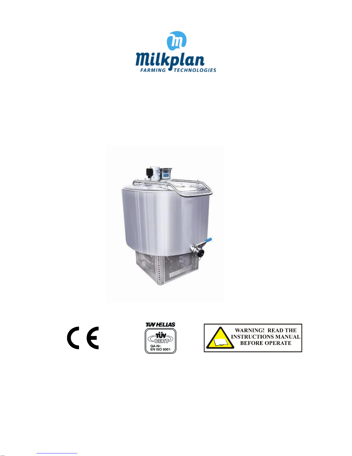
OPEN TYPE MILK COOLING TANK
IC 50 – IC 300
INSTRUCTION MANUAL FOR SAFE AND EFFICIENT USE
MILKPLAN A.E. ΗΜΕΡΙΔΗΣ - ΜΑΚΡΟΠΟΥΛΟΣ
EΞΟΠΛΙΣΜΟΙ ΒΙΟΜΗΧΑΝΙΩΝ ΓΑΛΑΚΤΟΣ & ΚΤΗΝΟΤΡΟΦΙΚΩΝ
ΜΟΝΑΔΩΝ Α.Ε.
3Ο ΧΛΜ. ΛΑΓΚΑΔΑ – ΚΟΛΧΙΚΟΥ, ΘΕΣ/ΝΙΚΗ
Τ.Κ. 57200, Τ.Θ. 212
ΤΗΛ/FAX: +30 23940 20400
sales@milkplan.com
www.milkplan.com
MILKPLAN S.A.
IMERIDIS - MAKROPOULOS
DAIRY AND FARMING EQUIPMENT S.A.
3rd KM LAGADAS - KOLHIKO NAT. ROAD GR 572
00, P.O.BOX 212
TEL/FAX: +30 23940 20400
sales@milkplan.com
www.milkplan.com
30120

2
CONTENT
1. INTRODUCTION...............................................................................................................................................................2
2. SAFETY RULES AND GENERAL INSTRUCTIONS .................................................................................................................3
3. PRODUCT INTRODUCTION ..............................................................................................................................................3
4. LABELING ........................................................................................................................................................................4
5. INSTALLATION INSTRUCTIONS ........................................................................................................................................5
5.1 INSTALLATION PLACEMENT ............................................................................................................................................... 5
5.2 MILK COOLING TANK LEVELLING ........................................................................................................................................ 5
5.3 ELECTRICAL CONNECTIONS ................................................................................................................................................. 5
6. OPERATION PRINCIPLE ....................................................................................................................................................6
7. DESCRIPTION ..................................................................................................................................................................6
8. TECHNICAL SPECIFICATIONS ............................................................................................................................................7
8.1 GENERAL ............................................................................................................................................................................. 7
8.2 POWER SPECIFICATIONS ..................................................................................................................................................... 7
8.3 MAIN DIMENSIONS ............................................................................................................................................................. 8
8.4 CONDITIONS OF MEASUREMENT FOR THE PERFORMANCE OF THE REFRIGERATING UNIT ............................................... 8
9. USING THE TANK .............................................................................................................................................................9
9.1 COOLING CONTROLLER ....................................................................................................................................................... 9
9.2 ADJUSTING THE BASIC PARAMETER VALUES OF THE XR80CX ............................................................................................ 9
10. MILK COOLING TANK MAINTENANCE - CLEANING ........................................................................................................ 12
10.1 CLEANING THE TANK....................................................................................................................................................... 12
10.2 CLEANING THE CONDENSER OF REFRIGERATING UNIT .................................................................................................. 12
11. SAFETY MEASURES........................................................................................................................................................ 13
12. MALFUNCTION AND TROUBLESHOOTING ..................................................................................................................... 14
13. MECHANICAL DRAWINGS (MACHINE PARTS) ................................................................................................................ 16
14. ELECTRICAL DATA AND DRAWINGS ............................................................................................................................... 17
14.1 ELECTRIC LINE OPTIONS TABLE ....................................................................................................................................... 17
14.2 ELECTRICAL DRAWINGS .................................................................................................................................................. 18
15. WARRANTY CERTIFICATE .............................................................................................................................................. 24
16. NOTES ........................................................................................................................................................................... 26
17. TECHNICAL SUPPORT .................................................................................................................................................... 27
Copyright © 2012 MILKPLAN ............................................................................................................................................... 27
3
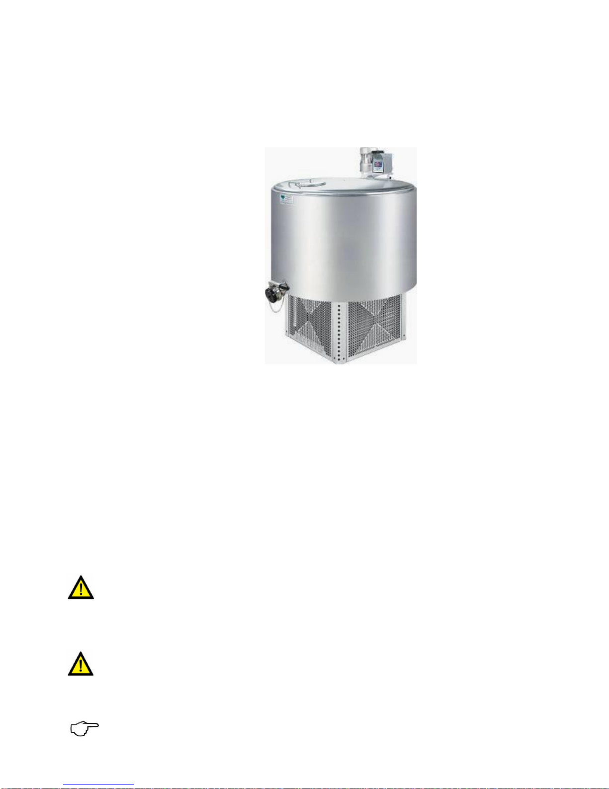
1. PRODUCT INTRODUCTION
Your new MILKPLAN milk cooling tank is designed and manufactured by experts in cooling and conserving milk. It is constructed
using the most modern equipment and technology.
Milk refrigeration is accomplished via a stainless steel straight direct expansion evaporator plate, operated in an economical
way and for maximum performance.
The materials used for the construction of the milk cooling tank are of the highest quality in the European Trade Market and
guarantee a long life and reliable operation.
The controller is an Italian Dixell type with an error of less than 1%.
The agitator motor is made in France by Sirem and its power is 90W/230V/30 rpm (in types of 50 ~ 1200 lit).
The closed type condensing unit is made by L’Unite Hermetique, a trusted name in the European compressor market.
The base of the milk cooling tank has been designed for safe operation and easy maintenance. The refrigerating unit and the
control panel are well protected from external environmental conditions and from small animals and rodents that could enter
the refrigerating unit and cause damage.
2. SAFETY RULES AND GENERAL INSTRUCTIONS
During the design and construction of this machine everything has been done to make your job more efficient and secure.
However, caution is of great importance. Prevention is better than regulation.
This machine is designed and constructed according to the Annex V directive 98/37 EU and the ΕΝ 292-1, ΕΝ 292-2, ΕΝ 294,
ΕΝ 349, ΕΝ 418, ΕΝ 1672-1, ΕΝ 1672-2, ΕΝ 60204-1standards.
The exclamation point within an equilateral triangle is intended to alert the user of the presence of important operation and maintenance (service) instructions in this manual. Upon seeing you are highly advised to pay attention to
the warning and be careful of any accidents.
After this symbol an instruction follows.
3. PRODUCT INTRODUCTION
ATTENTION! This manual is an integral part of the milk cooling tank and must be kept nearby in a safe place. This
should be made known to all users. Do not expose this manual to rain or moisture.
Read this manual regardless of your previous experience. A few moments of careful reading will save time and will prevent
many problems. Carefully read the instructions before the start-up of the machine, normal use, maintenance or other functions
on the machine, paying close attention to the following orders and warnings.
Place warning stickers on the machine and replace immediately if they have been lost or are not readable.
4
In order to prevent or reduce risk of accident, the machine should only be operated by adequately trained and
responsible staff. Untrained users should never operate the machine.
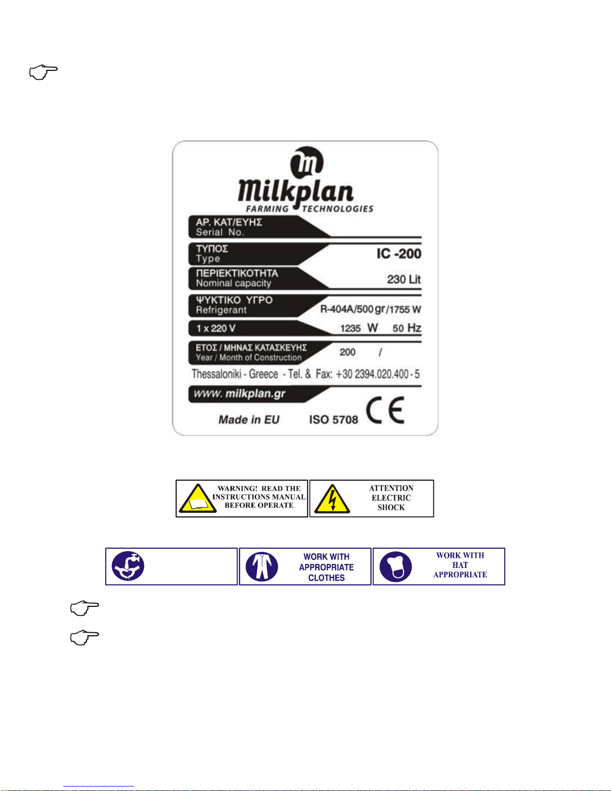
4. LABELING
The manufacturer’s label should be visible at all times as it contains essential information about the manufacturer (address,
phone number, fax) and information for the proper installation of the machine (the model, serial number, year of manufacture,
refrigeration capacity in Watt, electrical power in Watt , voltage, refrigerant type and quantity ) and the CE mark.
WARNING LABELS
The warning labels are to inform the operator of the machine or the equipment and about the remaining risks despite all the
measures adopted.
Due to the nature of the tank contents, strict hygiene rules apply. The following labels should be placed where all employees
can see them.
The inscriptions (warning labels) should be affixed in a visible, easily legible and non-removable spot on the machine
or on to a data plate attached to the machine in such a way that it cannot be removed or become illegible during
the lifetime of the machine in the normal working environment.
Keep labels clean and replace them immediately when they become detached or damaged.
WASH YOUR
HANDS

5
5. INSTALLATION INSTRUCTIONS
5.1 INSTALLATION AND PLACEMENT
The milk cooling tank can be installed indoors or outdoors. It is very important for the milk cooling tank to be installed in a
well-ventilated place with a water supply.
If the tank is to be installed indoors, make sure that the location has sufficient ventilation. Place the tank such that its condenser
lies near an opening in order to allow waste heat to be efficiently discarded.
If the tank is to be installed outdoors, it must be placed under a roof so that it cannot be affected by weather conditions (rain,
snow, etc).
It is also suggested to place the milk cooling tank on a flat concrete surface. Placing the tank on a flexible or deformable surface
can result in inaccurate measurements.
5.2 MILK COOLING TANK LEVELLING
Level the milk cooling tank using a hand spirit level. Open the lid of the tank and place the spirit level on the extremity of the
edge of the tank, as shown in the picture below.
Adjust the footings at the base of the tank until it is successfully leveled in both axes.
It is very important to precisely level the tank so that the volume measurements can be accurate
5.3 ELECTRICAL CONNECTIONS
An authorized electrician must complete or verify the electrical installation before placement of the milk cooling tank.
Tanks can be supplied with a variety of voltage and phase specifications. North American tanks are usually designed to operate
on single phase, 120 Volt, 60 Hz power. Other voltages and phases are available. Each tank is equipped with a label indicating
the proper voltage, current, frequency, and phase requirements.
6
The cables must be in sized proportion with the electrical power of the milk cooling tank. See table 1 of the appendix in order
to choose the type of the cable.
The cable must be straight, without coils (twisted extensions of electrical cable, etc.).
The milk cooling tank power must be supplied from a separate electrical line that is protected with a fuse or circuit breaker for
electric motors at the electrical panel.
Powering two milk cooling tanks from one fuse is forbidden.
The electrical connections of the milk cooling tanks of over or equal to 500 liters capacity must be inside the electrical
panel, and the electrical line must be connected to an industrial type socket.
ATTENTION! For your protection, the milk cooling tank must be provided with a grounded protective conductor of
suitable capacity to ensure the proper grounding of the tank.
After you have performed the electrical connection, measure the voltage loss in the cable by using a voltmeter. While the milk
cooling tank is operating, the voltage loss must not be greater than 3% of the electrical circuit. This measurement should be
performed while the compressor is operating.
Excessive voltage loss at the feeding cable can cause serious damage to the refrigerating mechanism, and is not
covered by the guarantee.
NOTE: Wrong connections at the terminal blocks or the socket plugging can also cause excessive voltage loss.
6. OPERATION PRINCIPLE
The milk cooling tank is especially designed and constructed for the refrigeration and conservation of milk, and to maintain
high product quality. Refrigeration must occur immediately after collection to minimize the possibility of spoilage of the milk.
The tank cools the milk by using a refrigeration unit. Homogenous refrigeration is achieved by an agitation paddle, which is
rotated by an electrical motor and mechanical reducer. The insulated walls of the milk cooling tank help keep the temperature
stable by reducing thermal loss.
7. DESCRIPTION
The milk tank vessel is made of stainless steel 18/10 AISI 304. The vessel consists of two walls. Between them there is environmentally friendly polyurethane foam insulation, which is inserted under controlled infusion. The agitation motor mechanism
is mounted to the tank lid and directly connected with the stirring paddle. The paddle is constructed of stainless steel and has
two shaped ribs at both its diametrical sides. This shape has been chosen for better and more equalized stirring of the product.
A dipstick and a calibration chart are located inside the tank.
The agitator motor and the control panel/controller are located on the milk cooling tank lid. This controller is used as a thermostat, thermometer and a stirring state controller. The milk inlet of a Ø175 diameter is placed on the lid, too. A handle is
placed on the front of the cover, and is used for opening the lid.
The milk outlet valve (DN50, Ø52) is located at the bottom of the tank (models IC 100-300LT). The tank base is made of stainless
steel and can be completely dismantled. It consists of the upper and the bottom cover, four adjustable legs, four footing-bases
and lateral covers. This has been designed for safe operation, easy maintenance, and full protection from various weather
conditions and the entrance of small animals and rodents in the refrigerating unit. This protection is achieved by four stainless
steel covers placed at the four sides of the base. These covers are perforated so that the heat produced by the condenser and
the compressor can be easily emitted. The perforation holes have dimensions that prevent the entrance of small animals and
rodents into the refrigerating unit. In models IC 400-2000LT the refrigerating unit is placed adjacent to the tank, also protected
by perforated stainless steel covers.
The stainless steel tank cover has an adjustable, gravity-activated safety switch to interrupt the agitator motor operation when
the cover is opened. When the cover is closed, the stirring operation is re-enabled.

7
8. TECHNICAL SPECIFICATIONS
8.1 GENERAL
CONSTRUCTION: Stainless steel 18/10, DIN 1.4301 (AISI 304) for inner and outer tank vessel.
TANK TYPE: Vertical type cylindrical tank, free standing, smooth inner sides, rounded angles, perfectly polished welding, ad-
justable legs for uneven floors. Direct expansion bottom designed to ensure total drain of tank. The design of evaporator plates
prevents milk freezing even at low milk volumes. Crash test at 60BAR. Function pressure: 30BAR. Fine insulation precisely
controlled infusion of high – density environment friendly polyurethane foam. 30rpm (90W) single-phase agitator motor for
IC 50 – 1200liters, 30rpm (120W) single-phase agitator motor for IC 1500 – 2000liters , stainless steel lid without any screws
inside and one-piece agitator (without joints). Automatic stop of the agitation motor in case the lid opens. Milk inlet 180mm
and stainless steel cover. Elevated parts (opening handle, stirring motor and electrical control panel) for easy cleaning. Milk
outlet and milk cooling tank evaporator plate inclination according to the international standards (ISO 5708). Stainless steel
springs for easy opening and closing of the milk cooling tank lid (for IC 200 – 2500 liters). Stainless steel dipstick and standard
calibration chart. IP55 panel for electric instrument (Applicable Standard: EN 60529/91, Applicable directives: LVT 73/23/EEC).
Stainless steel 2” sanitary fitting to accommodate user-specified output valve. Perforated stainless steel condensing unit cover
with removable sides for easy maintenance and for the condensing unit ventilation – protection (Patent No. : 1004080) for IC
50lt-1000lt.
CONDENSING UNIT: Close type condensing unit compressor by L’Unite Hermetique, coolant type R404A (full ecological).
A solenoid valve, high pressure switch, low pressure switch, high pressure switch for the second run regulation (Models IC
1000-2500lt) on the refrigerating circuit) protect the condensing unit and improve its performance.
INSULATION TYPE: INTERVOL RFN-24. Two components polyurethane rigid foam system. Blowing agent used is HCFC-141b
(CFC – free system). Thickness: 45mm. Density: 40kg/m3 (DIN53420). Compressive strength: 20kPa (DIN53421). Thermal conductivity, 24C: 0.023 W/m K (DIN18164).
PANEL FOR ELECTRIC INSTRUMENT: PROTECTION CLASS: IP 55 class-standard (Applicable Standard: EN 60529/91, Applicable
directives: LVT 73/23/EEC). TYPE: Tank mounted.
MILK CONTROLLER - THERMOSTAT: OPERATING TEMPERATURE: +0 +60C. STORAGE TEMPERATURE: -30 +85C. POWER
SUPPLY: 230V – 50Hz 10%. POWER ABSORPTION: 3VA max. MANUFACTURER: DIXELL SRL, ITALY. FUNCTION: When the compressor reaches the set point, it stops its function and the auto agitation of milk begins for 15minutes pause, 3 minutes agitation and so on until the milk temperature SET+ Hy when the compressor starts again. In case of probe failure , the output is
according to parameter “COn” - Compressor ON time with faulty probe (range: 0 255min, val.15min) and “COF” ” - Compres-
sor OFF time with faulty probe (range: 0 255min, val.30min). Note: All of the milk controller parameters are adjustable.
DIPSTICK: High precision stainless steel dipstick (AISI 304) for easy and direct volume reading in mm.
8.2 POWER SPECIFICATIONS
(Note: Other tank sizes, voltages and capacities are available.)
Milk
Cooling
tank type
Maximum
capacity
Liters
Weight
Kg
Fan cooled
condensing
unit type
Voltage
Refrigerant
type
Refrigeration
capacity
Watt
Maxi-
mum
Power
Rate
Run
current
Maximum
current
Number
of milking
IC 50
60
40
AEΖ9440Z
L’Unite
115V
60Hz, 1~
R 404A
743W
3/8Hp
636W
5.4A
3,00Α
2
IC 100
125
60
CAE4450Z
L’Unite
115V
60Hz, 1~
R 404A
927W
3/7Hp
756W
8.3A
4.19Α
2
IC 200
230
100
CAJ9510Z
L’Unite
115V
60Hz, 1~
R 404A
1972W
1Hp
1299W
13.7A
7.10Α
2
IC 300
332
110
CAJ9513Z
L’Unite
115V
60Hz, 1~
R 404A
2485W
1_1/8Hp
1683W
16.1A
10.10Α
2
 Loading...