

Page 1

•
RADIO
~
AND
SETS
AUXILIARY
rL
Af;Slf'I
accorda n
il
uthorily
19.4;;.
SCR-194
AprD
CA
TION
Cil \lith
or
w ,n , Circul
17, lW
CA1W·E
p<
1r. \ :;, A
AND
SCR-195
EQUIPMENT
/
ar
I.U~n
I{
:1~ O
49 •
,
in
':
'i,
hy
•
,
I
Page 2

,
,
TlDCHNTCAL MANUAL)
NO).
11
~238
.TJI[
WAR DEPAllTMlllNT, ,
WAflBI
l'Iot'O!'I.
AprU
11-238
11.
11142.
UI13
,!l
RADIO
S
IICTION
I.
II.
SETS
llineral.
Employment.
SCR-IM
Purpose
General description _________
Ma
jor
component parts
Description
Location and selectio n of freq.uencies
"",ttmg
"'-
General operatioll _______________________
Portable operatioll
Vehicular operation
Service _______________________________________ 10
. .
up
AND SCR-I95 AND AUXILIARY
EQUIPMENT
_________________
________________________
of
parts
eqUipment
______
_____________________
____________________________
_________________________
!
·u
__
__
.....
_
_
_
_
_
_
_
_
_____________________
__________________
__________________
___________
____
_____
rll'
/I:
i'
#;)-
...
ph
1
2
3
~
,
,
6
7
8
,
Storage _________________________________
III
. Detailed functioning of parts.
Rad io set
Radio set Se
IV
. Supplemental
Freq
Frequencies and dial settings, rad io receiver and
Parts
V. Remote control equipment R
Purpose
Setting
Operating
uencies and dial settings, radi o receiver and
transmitter
transmitter
SCR-
R-19S
data
l94
and
____________________________
_ __
pa
BC-222
BC-322
list
__________
____ _________________________________
up
and oollnecting_
________ .:_
___
__
11
12
__________ ___
rta list.
__________________________
___________________
___________________________
C-.66.
______
__________________________
__
________
_____
__
_
_
______
_
__________
IS
14
Hi
16
17
18
19
Removing from service
Detailed
Parts
VI. Antenna equipment RC-63.
Purpose
Setting
Operating ___________________________________
H.....
-:;-_IDovmg
Pa
rts
functioning
lisL_______ ____
____
up
. fro .
Iist.
________________________________
and connecting______________________
m servlce_________________________
______
________
1
_________________________
of
_________________________
parts
_
_______________
___
______
M558598
Or
•.•.
UNIVERSITY
Of
___
_
__
_
_____________
1<
..
C/o.lJfORN
lA
20
21
22
23
24
25
26
27
Page 3

Tl!I(
11--238
,
..
SIGNAL
COflPSl
VII.
VIII
Purpoee
Oem".1
Major
Do!ecrlpUon
________ __________
d
~l
rompo
Carrier FM--32
Purpoge
LIt!tO<lnptlOfl
~
---.
lEImployUlent--
. Bag BG-82.
Purpoge ___
~rlptlOn
~--
.
EdnployUlefll-
pll
o'
'_
___
..
_______________________________ +
.... m
of
JIll
r1ll_
)lfIrtll__
___ _ __
__
___
and
_______________________
_______________________
.
fra
me FM--33.
______________
__________
--------- ------ ------ -----------
___
_____
______________________
.
_________
_________________ _
_______
---- -----------------------------
SEC'J"ION I
GlEINlEIRAL
_ _____ ________ ____________________
________
_ __ _ _
___ _ ___ ______ __________
__
_ _ _ _ _ _
__ __ __
__
__ __ _ __
__ __
____
_ _ ___
Parqrop/l
_ _
___
__
__
__________ 1
_ _ __ _ _ _
___
__________ 4
I'a"VOP~
_ _ _ +
__
_ 28
29
30
31
_
••
sa
__
__
2
3
1.
Purpo8e.~Ra
point-to-point
and
are hi
infantry
2.
General
ghly
regiment, respectively .
portable, loll' power,
transceivers.
voice communiclltion within
deacription.--<I.
They
dio
Ilre
sets
u9i!d
SCR-I94
Radio
high
to
OOffiDlunicate
5 miles. All the equipment required
is
carded
hicular operation
a
mast
scopi
tor'
ng
s back. Radio
vehicular operation
the vehicular
when requ
on the bllck
base
with
tubular
antenna
ired
.
of
radio
meaIlll
the
set
SCR-
of
connection to the
opentor
195
Itntenna used when
set
but
Power
SCR-I94
antenna
aooessorie
for both
does
equipment RC-67, which compr
s,
transmitting
is furnished as a
and
SCR-
sets
I95
are
the
artillery
SCR-I94
intended
battalion
and
SCR-
frequency sets which include
for
transmission
in
ineludes
the
set
not
O\'er distances
and
It
canvas bllg.
stee1
set
mast
~ons
to repJa.ce
is cllrried on the opera-
include
aC<ll:lSSOri
up
reception
For
the
es for
separate
and
receiving is sup-
for
19
to
ve-
a
nd
tele-
i!188
un
it
5
plied by one
b.
Radi
megacycles
dry
o set
lUring
battery.
SCR-ll»
has s frequency range from
two oscillator coils,
400 kilocycle separation."
range from 52.8 to
aWords
•
The
"a~
which
nnl)'
heen
tI:Ie
sa
ehalmels with 400 kilocycle sep
lI.
utborlr.ed ch
n~ed
11.
1110
400 kUocrcle cbanuel
hllY
at
...
400
500
6ri.8
llnn
kllocrdes;
kllocyde
el
me"nu
....
1!Cll
t ,
Radio
:ycles using one oscillator coil,
parlltlon
howen'~r
c
hannel
1ee.
or
2
and
set.
""ale.
SCR-19ri
fIldlo
.
lI1~n:r
Care
Or,~,
UNIVERSITY
affords
lI.fIItio
seta
~nc"
SCB-UH
....
muOl
.1
t....,.,
Of
C/o.lJfORN
<n.7
62
channels
has
a.
frequency
n (see sec.
and
,
~
IulYe beell
be
e~erdaed
lA
SCR-UlI'i
to
I.ned
to
ri2.2
with
and
IV
) .
UIII'
Page 4

•
,
RADIO
SETS
seR-I'"
M.-o eCR-
U6
TJ(
11-238
,
Then!
design
band
i
~
of
no
and
the
opera
cons
SOR-194
ting
tru
ction are identical except t
diffe
is
l''e
nce between the two sets. The general
covered by two interchangeable
the operator's equipment oonsists of
•
(
hat, the
a.
micropho
UNIVE~\lTY
Of
CAlifORN
frequency
coi
ne
T-24-E and
IA
ls, and
Page 5

TId:
.
11
238
...
SIGNAL CORPS
•
headset
SCR--IM
operator's
3.
The
two
parte for operation and transportation.
(1)
00-11
HS-22-B
is
handset!>
Major
covered
component
, whereas Ihe frequency band
TS-ll
radio set SCR-l94 and associated equipment is divided into
For
on
portable use the following equipment is carried
tbe
back
of
mitting and receiving
-t---
1.
•••.••
1.
.•..••
1.
....•..•
1.
.•.
I
.••....•..
1 __ •••••••
1._
•••••••
1
___
••
...•
____
. • '
.•.
•.
• .
. . . .
.....
...
• _ _ _ Radio
_. __
• •
An\.enna
..
Bag
Battt!ry BA- 32
Headooet
Microphone
Tube
••
Tube
BG-71-
VT
VT-67
of
the
by
a single ooil and there are provided two
- E.
part..--a.
Radio u t ,
SOR-19.
the operator and constitutes a complete
unit
neel",",
with antenn!, and power supply:
-
AN
- 29--B t .
••••
H8-n-B
T-24-E·..........
- 33
..••.•••
••••
and
__
._
••
••.••••
••••••••
• •
....
•......
trall.llmit\.e r B
__ • __ • __
••••••••••••
------
.
••.••.•••••••
•••••••
••••••••
.
...
.•
._.
__ . __
••.
••
...
..
..
..
C-
222
•
•••••••••
••••••••
••••••
..•
. . .
•.•
••
_._ • • _
WMP'1o
••
....
..
•••
•
radio !Il'It
(fig. 1).-
in
bag
trans·
_"".
."
,,,
>200
.
.."
&00
.
.
..
..
..
..
,
AD_
_ . j
•
__
• N
NoJ.N·.A
__
AN· ......
I
B8-,..A
T-"'A
bo
__
.. H8-
.
T_"'S
IUbolitulOd
-..
2t-C
od
.....
. T-1'I-C.
lor
.)
bo
..
_
...
"'UulOd
T-1oI-D
AN· ...
...
(2) Auxiliary equipment and spare
CH-33 as follows :
L
.....
2
•...
1. ..•.....•
1_
. _
1
__
•••
1 • •••• _
2
__ •••• _. __
2_
...........
~
feet
..
.••
......
•..•....
__ •••
••
........
....
___
.
Ant.mna
Banery
_ . .
__ • Cbeo,"
...
Binding
_.
Bo~
••
C
Tube
.
Tube
Wire W- I26 {or
--
AN-
BA
poIt
BX- 13
CH
ord
CD-I9li
VT
- 33 {
VT-67 {epare) __ ______ • _____
N-B'
- 32 (epa ... )
TM
••...
- 33 •••••••
••••••••••••.•••
apa
--
(
~
- 176 (.pare
•.......
••••••••••.••.••••••••
... ) __
W-~-
S. bu l
lor'
T-_,
1.,
.....
.........
H8-22-S
parts
--
... ) _. ______ •
________
.•
._
•••••
..
_ . . _
__
) •
.•..•••••••••
.............•..
••.•.
___
....
bo
...
botl •
-
----
.........
._.
________ _
....
AN·..c
.
.,t<Id
an>
..
• • _
•••
_.
__
... _ ..
lor
10 _ lUI
_OJ'
Total
....
.....
2S.
lor
T·"'Z
carried in chest
--
-
__
..
.
."
...
••
·
•
_.
__
",00
,&
10
.....
.
.
..
..o'
"
.
..
...
.
..
.30
,
_.
'AD
.......
(Ne
AN·lIP
~_A
.....
bt
..,botl
.....
_ P: , ...... J
.ulO<!
<.
Ior
..
\
I~I
_
AN_S,
•
bu
...........
Or,~,
UNIVERSITY
.11<"",
Of
AN·..c
C/..tJfORN
IA
1--
10 _ ...........
--
Total
M
14
IorL.b.lo
Page 6

b.
Radio
let
RA
'OIO SET:> SCR- I U " NO sca - ue.
SC
R-
J96
(fig. 2)
.-
The
ra
dio set
TM
....
SCR-191S
11-238
and its
9 )eiated equipment are divided into two
tran
BG-71
mitti
s
1 _____
I .
I
I
2.
1.
I
L
sportation.
(1)
For
on the back of the
ng
and
¥ (2) Aux i
pare
..
.. _ ..
... _ ...
parte
••••
____ . __
______
__ .... __
___
.. ____ . __
.... ___
._ .__
._ .
__
..
. _. _ __ T
__
_...
_.__
. _
portable use
l'eOOivillg
liary
are c
..
__
___
equipment
arried
A.u.pte
Antenn.
Bag
B.ttery
H.n
Radio
ube
Tube
r 80-1>2
BG-7L ________________________
dset
receiver
VT-3:L
VT-67 ______ . _
th
e following equipment is carried
opemt
unit
with anrennll and power s
in chest
___
AN-
BA-32
TS-II
30-
________________________
-E , ____
.nd tr.""mitter
••
____ _
or and constitutes a complete
neceSSllI'y f
CH-33
__________________
B , _______ ____ ___________ _
. _________ __ . _
•• ___________________ _
••
___________
or
as follows:
B
par
vehic
C--
3Z2_
._. _ ••
ts
ular
___
_____
....
•..
for
operation and
upply:
operation and
11'0.1"
_ •
__
_
••
__
__
. _
__
_
in
tran
1.
bag
__
."
. 00
.00
'
12. 00
3.
.00
.>0
.
s-
00
>0
' &
"toun.
'a
...-
QuoDtI',
L
------
,.
---
2 _____________
L __
--------
L -
_._----_._-
-
----------
'---
L
2
2._.
2_ . .
-
.-------
._._._.
_.
.....
feet
A N-301I1&7 be
~l/-A.
----
--
---_._._-
--
-----_.
___ ...
___
.
._-----
. . -
. . _
_
----
_-
..
"
...
I1o<I
TI
H I-
R.
Antenn.
B.ttery
Binding
So>
Cheflt
eo",
M
M
MM
Tube
T
Wi..,
Mt
Mt
o'"
aX-1
C
t
"""tion
W- I U
,u,,",
TII-H-C,
CH
D-19~
b_
"""
VT
VT-67
Ior."toun.
AN-
BA-
,..,
tion M8-1>O
- 33
30-
32
TM-176
3 ______
-33
________
_
.
MP-Z2.
M
("pa..,)
(o
pare
,
,,
AN_B
TII-H
_D
..
'
"~
(sp&re) _
B
•
(8J>.re) _
___
___________________ . _
___________ _ • .
S-51
.........
______________ .
"
_____
spare) . ____
spa..,)
TIJ-ll
8pa""
. (N o A
_' '*" be
.
-
----
. .
---_.
) .
______
_ . •
__
N_A
"'boll,,'.'""
---
. . . . . ----
. _._
__
._ •.. _. _
__
••••.•.•
._
. • . . . _
"
..
--_
) ..•..
W-
"
9)
.. _ ..
___ . _ ..•......
__
---_
..
. . •
........
_.-
_._ ... _
----
__
...
..
h
._-
--.-
-_. -
__ ._
_.
--
..
--
--
..
_.
__
boon
"'"
-
Total
~.
"""d
W
",h,Ifl
TotaJ
...
26. 8Ii
)
TII-H-!
__
00
•
00
" .
..
·
,.
,.
'"
.,
" L .
·
00
•
·
,.
'"
00
,.
·
,.
·
30
•
...
"
4.
Description
'lJO-m
and
transmitter
and BC
of
-Sfe
parta,
(figs. 3 to
--a.
11
Radio
recd
!ler
~
and
incl.) .- All elements
tT(nllf1nitter~
of
the
reeeiver
are chassis mounted and contained in an aluminum-
•
Or.
,",I< "
UNIVERSITY
Of
ClillfORN
lA
Page 7

TM
11-238
•
•
-
•
of
-"
2q
•••
•
.,
"
u·
,
......
"."
,
•
•
j
SlGNAL
CORIB
•
•
•
,
! ·
.'
• •
."
.'
» 0
•
•
>
•
,
-
1
-
,
-
•
•
I
•
,
•
,
•
,
•
"
•
•
•
•
I
•
<
•
•
•
,
•
, .
-.
• •
" .
,.
•
-
,
• f
•
g
"
i
•
•
•
•
,
•
•
,
-
•
•
i
,
•
•
•
~
"
•
•
,
"
•
alloy case. 111is
from which
Iilrllp,
bf"u.ery
I)Jug
an
in
in t
it
antellna mounting, and
pillet. Connection to the baltery
he
bottom of
unit
deri\
isdesiglled to
'1\t
ilS
power.
th
e cha
(,
6t
Th
two
ssiH
6
dil'fl(:tly 0
e case i
strop;! which serve to hold the
lind '
Il
UNIVERIITY
11 top of
ll
fiued
i
~
completoo t
socket in t
0.'9,,,..1
fr
n
Of
CAliFORNIA
II
b.uel1'
wi
th a carrying
he
top of
BA
hroug
--32
h
II.
th
e
•
Page 8

,
"
RADIO S
ET
..
SCR- i U4
AND
SCR- \
US
TM
11_238
•
I
I
battery. Aceess'w the
!h e
li
Mp
oXlils
radio sets
IId
diti
mounted on
0
11
the
is closed,
To remove the tube
slid es at t
filly
ona
l s
chllssis.
and
he
sides aud opening
then
SCR-l94
be
instu lled or removed.
and SCR-195 hav e devices added
upport for
th
e inside of the
TI
~
c
the sp
ring
VT-33
top
of the chassis
the tubes.
top
ap
fi
ts
over the
clamp
fits Il
(rom the ciamp, the le\'er
may
the
Th
ese consist
cover,
lin
d a spr
tube
round Ole ba
be
gained by relea si
cover. Tu~
Lat
est
VT
se
procurement
of
an
insulating
ing
-67
cla
when the
of the tube VT-33,
011
s
and tuning
s of
to
provid e
mp
mou
nted
cover
the side
ng
ca p
of
I
Y'oG"
a._Ha ~
the clamp is
The
openi
side
unit,
both
is
e1I'
chllS!lis
ng the front
of t
he
except
receh'ing
chan
ected
ged
by the
lo
...:e1>'01'
pr
essed with a pencil, acrew driver, or si
may
elise
for
and
from
reillY
ond
t
...
n .
...
U~r
flC-~2~.
balte
be
cover
and
r1
.. , ....
and
removed to f
and taking
one
in the rear.
..
acilitate
a few minor items,
tran
~eiving
smitting.
to
UK
- 10, which is
11
tr
llllsmin
7
Ute.lor ,-....
te
.....
_
~"tl"l
ins.pection or re pair
out three
The
employs
screws, one
receiver
the
le operation
ing
in
turn
UNIVE~\lT Y
by alt
Or;gtr
cont
.Iff"",
Of
CA
Ilw
..
l,..
.
milar
and
SIlm
tran
e elements for
of various el
ernate
rolled
lifORNI
connections
by
the
A
co,
rl''''
at
smitte
ements
.Dd
object.
by
either
r
swi
tch
Page 9

TM
11
-238
•
SIGNAL CORPS
•
"au
..
4,_II..dloo
0'e<.'01
...
. .
~d
_I.
t
...
~."'HI~,.
~·llh
4
00
I
IC--ZZlI.
k.
ou\>CIt.loI""
(.ont
..
«I, .....
OO
b'O,·ed obowln.
,
dial
8
<
•
o.>9"olff"",
UNIVE~\lTY
Of
CAlifORN
IA
Page 10

TM:
11-238
on
Ole
teewr
circuit.
justlllent,
and fila
cates
microphone or hllndset.
and radio -frequency oscillator in
Contro ls are p
ca.
libration 8witch,
ment switch. The meter on the
the l'oltage
to conneet the I
b.
DWl ,e
BC-322 are
ak
eRch
RAD
IO SET;; SCR-
The
ro\
on
the
lIIlId!;e
t or headset and microphone.
ploftl.-Rn
'ided
fila
ments,
dio receivers and transmitters BC-222
llS
ca
libration adjustor,
provided with H dial
I'H
!le
ANI)
t
Usell
a.
SC
R- I U
a superregeherative de-
modified form of Hartley
follows: chlumel
and
left
the
!<Cale.
aide
!IOCkeL
which is mark
•
or
frequency
fil
ament rheostat,
of
the panel indi-
llt the r
ight sent
ed
and
off
IId
eR
in
-
I
r
400
are
cured
screws. U
interchange
screws,
Tllbles
(
kilocycle subdivisions and printed on a metal plate. Many sets
equipped a.I
to the panel, one o\'
se
int
erehllllbte
of fl'l!quenCi
Ea
rlier sets were
of
Ole
!!O
with a
the
400 kilocycle scale only is now
dial scale
the dilll
es llnd dial divisions
provided with
600
er
plates
kilocycle scale, the two scal
the other, by means
of live
auth
it ill
sc
ale plntes, and replace
necessa
a.
reversible
are
ry
to
gil-en
ce
remo\'e the five
in
lluloid dial scale
es
being se-
machine
orized. To
th
e screw
IieCLio
plate.)
e. A
an
nte/l1l
al
AN-
e9-
B
~
AN
~
B.-&ch
antenna
con
assembly of telescoping mmiel metal tubes which, when in use,
9
s.
n
IV
sists of
.
(
Or;gtr
UNIVE~\lTY
.Iff"",
Of
CAlifORN
IA
Page 11

TM
11-238
•
SlGSAL
CORPS
,
are
th
of
9Cl'(!wed
e case.
into plsce on the insulated antenna mounting on top of
Th
A.N-29-B dr
e radio set
aw
n o
ut
SC
R- I
94
usiug coil
largest or lower sections using coil
SCR-195
dra
wn out. The c
antennas are e:rtended to the pro
is operated with a
alibrat
ion of eith
ll
eight
per
is operated with all
C-
17-i
, marked A; with
C-175,
see
er
set will be oorrect onl y if the
lengths
marked
tions of
at
all times
D.
antenna
tw
The
eh'e
sec
radio set
AN
or
operated
tions
th
e ten
-3()...
D
,
"'''''U
1._I"'~IQ ~h'~r
«Ill
.~~
1...,.1100 "r
complet ely tel
parograph
8.
u~
".".
.....
esc
oped "'ith only o
nno
w
ro"pIl
l"e,
u
o.:-
Q~
"1
~n
......
..
<110' On 10ft
ne
sec
"Bly
.•
bOWIB
""
••
Ide
~
or
_ltI""
..
I~
tion in use as d
•
... ' ...
esc
•
or
.I!~
.
ribed
....
,
In
•
~
d.
J
I/
~I
sre
M
ma
de of high tensile stren
S--51 Il
re fitted with
sleeve snd
n blunt
point
u
climlil
th
read
MS-
lit
the OIh
J9
It
split sluUlk and screw lit one end lind a
at the upper end.
, It/S-1W.
l,rth
er.
M~t
Ends wh
10
alul lt/
S-.'.i/.-
steel. Mast
section ,\1
ich lire joined in
Or;gtr
UNIVE~\lTY
.Iff"",
Of
Th
ese
lIla
sec
tions
8-49 tenninat
CAlifORN
IA
st sections
MS-OO
and
!lOC
el!
IL':lSe
mbling
ket
in
Page 12

RA
DIO SETS SCR-
I9
.
AND
SCR-1911
Tl!il
11-238
•
r.o.;l:0 S
._
Rodlo
.... 1"'
ObQ
wlD,
ol>d
pi",
!ruomlu
,"'bl
eb
ftU
...
BC-:I2'~
Into
_kH
0, /:IC-:n2. "nelot, old<
QD
bo.\t~r,
11.1.
_32.
<Jf
eb
......
•
11
Or;gtr
UNIVE~\lT Y
Of
.Iff"",
CA
lifORNI
A
Page 13

TJd:
11-238
•
SIGN
AL
CORPS
,
,
12
Or;gtr
UNIVE~\lTY
.Iff"",
Of
CAlifORN
IA
•
Page 14
TM
11-238
RAbIO SE'l'S SCR-
have enameled
is 6Ilameled black
When
SeR-I94,
each
binding
W-l26.
9 feet
it
is
an
of
sections M&-49, MS-5O,
posts TM-176, one m
The
411,
4,
lower section.
and
MS-IH
marks
desirOO.
of
and
bears
to use a vehicular
antenn.a equipment RC-(j7 is
over-all length
inches from the top
The radio
for
use
in
vehicles.
sections assembled is 6 feet
shoulder
e. Ma&t
of
the lower section.
base
MP-f2.-The
the
lIlt
sam&
the
type number
AND
color.
SCR-IIl~
The
antenna
1llj(lOj.
ast
of
and
ba
the
to
MS-Ill.
se
MP
-22,
three
mast
the bottom
set SCR-195 include8
3%,
The
inches from the
mast
over-all length
base consists of a ceramic
•
body
near
It
and
sections assembled
of
mast
top
of
each section
the lower end.
with
the
It
radio
includes two
also includes two
10 feet of wire
the shoulder of
sections MS-:iO
of
these two
to the bottom
of
set
is
the
the
in-
sulator
tion
fastened
of
the
to
a steel
antenna
through
provided in the top of the
The
transporting
plies all the necessary
in
and
approximately
two
able use
web shoulder
three
steel
f.
Battery
the
the
or
g.
Bag B0-71
plate
top for
set.
three times
of
compartments, the
is designed to
vehicle.
BA-.'ffl.-This
making
Under
continuous operation the
20 hours. When used intermi
as'great.
radio
(fig.
seLs
12).-The
SC
straps silpilar
set
ali eleetrical conneetions required between
R-I94
main
plate
in such a manner as to
pennit
8n angle of 180°. A metal socket
insulator
pennit
is a block
voltages. A
canvas
and
to
those on the haversack.
one being used
to receive
fa
stening
battery
6·point
carrying
SCR-195.
mast
to
section MS-61.
an
upright
so designed
socket is
life
ttently
It
for
of
this
the
bag
is
has two
carrying
that
life
for
It
rota-
i8
on
the
it
sup-
provided
it
battery
may
the
is
be
port-
adjustable
comprises'
the
radio
receiver
and
operation.
carrying
the
1 headset
1 microphone
and
II.
pocket on
AN:..w-B.
the bag,
there
be inserted
to
the
weather
the top
set
and
of
transmitter
The
follow
RodW
other
ing
,~I
8O~19~
HS-22-B
the
To
permit
is a hole in the top
in
the
set
panel
Further
BC-222
or
BC-322 complete
compartmenLs are a pocket
equipment; •
1
T-24-E
aide
operation
and
a slide fastener in one side to
for
to
carry
of
of
prot
2 handsets
ing
the
the
ect the
when not in use, an additional
the bag.
This
Bap may
be
Rodw
«I
adapter
the
set
bag
antenna
while being
so
that
equipment
Dap
flLlltened
and
in
8C~J9~
the
ready
rear
S()....52
TS-ll
-E
AN-
29-B
carried
the
antenna
permit
in
inclement
access
has been added
down
with
the
tor
for
or
in
may
to
two
13
Or,~,
UNIVERSITY
.11<"",
Of
C/o.lJfORN
lA
Page 15

TlI
11-238
•
SIGXAL
CO
RPI!
,
"""'
•• la.-
,
Bcu;
•
14
• .
UNIVERIilY
Of
If,
(~
lIFORNI~
Page 16

TM
11-238-
•
RADIO
end snap fasteners,
turned ba
fastener.
ck
into a double fold
It
is
important
SETS
or
when the anten
SCR-
and
that
a double fold be used because a single
l\14
AND
na
SOR
-L
9~
is
being used
it
..
ma
fastened by the one center snap
y
be
fold results in snapping the fastener together inverted. When so
fastened,
tearing one side
h. Bo!};
boll:
provided with a
radio receiver Ilnd transmittel' BG-222 or B
posts,
necting separate
available. and to facilitB
cireuits.
the
BX
and
Il
battery cable.
The batteri
force necessary to use
of the fastener from
-13 (fig.
13).-This
soc
ket which fits the plug
It
consists of a
is designed to provide means
batteries to the set
fAl
the inse
es
aI'S
connected by means of the cable, a
to
the
unfasten it
bag
.
tid
mll.y
rectangular metal
at the bottom of the
C--322,
ill
case there is no battery
rti
on
of
meters in
several binding
rosult
of
BA
th
e several
ll
leads
in
oon-
-32
•
of
which are identified by stamped metal
posts, f
to indicate microphone c
plate
I
MPORTANT:
eously conneet
markoo M
connected with a
circ
a.s
thi
Caution: When making
BX-IS,
If
thi
sumultanoous!y. Do not
co
nnections even if the
our
on eit
her
side, serve to provide
urrent
,·oltage.
If
it
is
desirod to use this
uit
s.
IC
Do
ing
RO.
not
meters, each of the three pai
CU
R.,
RELAY
jumper
w
i~,
jumper the bind
s will short-circuit the battery.
or
changing jumper connections on box
be
sure tJlat the battery cable is disconnect
s is
not
done,
it
is difficu
lt
attempt
fil
alllent switch is tUnied off, unless
, relay
CUR., and
otherwise
ing
to avoid burning
to
markers.
~ady
cu
rrent, plate
connection of meters
box
rs
PLAT
th
ere will
posts marked
ed.
make
or
change these
TI
le
binding
cur
rent, and
witho
of
ut
simultan -
binding posts
E CUR. must
be
three open
PLATE
VO
LT
from the battery.
out
the
two tubes
jumper
the
be
S,
battery is disconnected.
(1) To provide operllting batteries if bat.tery
BA--32
is
not
avail-
ab le, the following Signal Corps batteries are suggested from among
th
oaa
which may be on
,~,
A (Ii!&mentl
B (
pl"te
e
(gri
dl ___ _____________ _ 13.5 _______________
M
(microphonel
___
. _________ 3
) _______________ _ 144 ______ ___________ ___ 6 B
__________
(2) The following cu
normal f
or
the
rad
io
hand:
___
___________________
4.6 __________________ __
rrent
sets
and voltage readings (approximate) are
SCR-194
and
SCR-19l'S:
__ __
2 BA-17
A-S.
3 BA- 27.
lIlA
- 27.
Or
BA-23.
Or
•.•.
UNIVERSITY
Of
1<
..
C/o.lJfORN
lA
Page 17

TM
11-238
•
R
eceiv~
Transmitter
Tra
Hela
. "
MIcrophone c
Plate
A variation of plus
i.
Ad
apter
fitt
ing pro,'id
two
90Ckets
r
plate c
nsmitter plate current
y cur
rent
"olt age
SO-6
ed
simi
e (
with a plug similar to plug p L-(;5
lar
SIGNAL
urrenL
plate
current
______________
______________________________
urrent
_____
CQ
RPS
milliamper
(modulatetl)
(u
nmooulated)
___
_________________
______
-<lo
____ Ao ___ _
do ___ _
uo ___ _
_______________________________ "ol
or min
fi
g.
us
10
14).- T
percent
is
he adapter
permi
consis
ssi
ts
ble.
of
on
to
90C
kets 8Q.-45
on
the other. A
e!!
__
___
_
21.5
45.0
35.0
18.6
35
to
60
ts __
IS
a.
small metal
one side and
ll
wmng
•
'
lS
within
T
S-ll- E, provided with
simultaneously. T
th
e P/luel of the
sockets
too
of
fitting.
nd
Th
e
he
plug of the
io
re\:
eiver and
uuit
th
se
l'\'e
e radio set
Ild
tnll
the adapter aceummodate the plugs
handset cords.
j.
lleatilJ
el'8
special c
o,'er
adjustable to fit
be locked in place. The
pl
This
(si mil
the welirer 's head and a lenther strap
ug PJ.r...51i
headEet
ct llS-tB-
ar
to
receiv
a.p
and a cushion M
the
which fits into 8
is
wearer by means
pa
rt
B (fig. lli)
er
R-14 exce
he
.-
The headse t
pt
C-
14l) ath ched to a s
adset cord C
jlLck
JK
of the radio set 8CU- t94.
combine light weight with <:omfort a
~
to enable the two handse
8C
np
ter
smitter U
that
R-196
fits into socket
each
C--322
on
con!!
is
, to
be
connected
80-45
, and the t wo
the end
ists of two receh·,
equipped
trap 8'1'-20
below. The Illtter is
of
a sliding s
D-WI
--38
nd
on
Ill
ay be wo
the
is
loo
,'e which may
te
rminated by a
mi
crophone
It
is desi
rn
und
brned
er
l.ll
on
of
the
wi
th
to fit
cord.
to
a hilt,
I
II
helmet,
or
with a
b"lUl
(
mask.
16
Or~tr
UNIVE~\lTY
olff"",
Of
CAlifORN
IA
Page 18

,
•
RADIO
SETS SCR-
i114
A."D
se
R-
iIIS
TM
11-
•
238
,
I
k.
M
it.
:
rop}IO'~
hand
cordage
mi
crophone with a !lII
CD-146
headaels H
connection
microp
hone
S-22-
to
the radio n!Ceiver
is
pllrt
T
,
-24-
II
ja
E'
(
fig
. 16).- T
'itch to which
ck J K-38
(for
he
mi
crophone comprises a
is
connected a cord
the attnchment
made of
of
one or two
B), a radio frequency choke and II. plug PL-too for
of
the radio set
find
Se
transmiuer
R- I
\)4
.
n
C--222.
Thi s
•
~II72·_
n
_
~.
(
17
Or""
UNIVE~\lTY
.
If,
Of
CAlifORN
'"
IA
Page 19

TM 1
1-
238
t.
Halldue T
ment.,
It
s cord
•
II
IIWitch, lind
is
identical with t
S-Il- E (fig.
II
high
SiG~A
17).-T
L
COR
his consi
PS
st8
of
II.
microphone ele-
impedance receiver mounted inlegrlll1y.
hat
of
microphone T-
24-
E
exce
pt thllt
<
~"
<IC"
18._
C_,
cu
..-a
""
.bow">6
'",
",,'>""10".'
•• "
.. ( .......
••
t>o.
,
bo
..
1!.X_13).
~tl"_~~
I¥
""
..
le<Ilu
..
,
_
18
Or""
UNIVE~\lTY
.
If.
Of
CAlifORN
'"
IA
Page 20

TlIt
11-238
RADIO SETS SCR-
jack
radi
by
of
of
incorporates a radio
a
JK-38
o receiver
means
each
radio
m. Oord
the
same
socket
80-86
is not includeod. (Connection
of
and
an
transmitter
adapter
set 8CR-19!i.
OD-1M
type
(figs. 1 and
as
that
frequency choke, a
on
the
nse the microphone or
set
than
fl.
videod
antenna
their
BiMiWJ
to
alford
to
the
cords allow.
po
rt
TM-176
a means of oonnectinjl the lead from
radio
!let.
80-52.)
used with
oth
er.
handset
(figs. 1
Wh
en so em
Uf
AND
OCR-US
of
BC-a22 in
Two
2).-This
the
It
is employeod when
at a great
and
2).-The
ployeod
this
of
these handsets are part.
is a
microphone
plug
PL.-loo
er
distal\ce from the
it
&....(I
two
handsets to
the
case is accomplished
12
-foot
binding
is
exTen
and
handset.
on
one
it
is desired to
post is
th
e vehic
IICreweod
sion
cord
end, and
radio
pro
ular
into
insu -
It
-
lator
videod
divided
to
ported.
ried in the same
from
Loeatlon "TId
!leUI".
aeneral
IN
o.
Ohest 0 0
for
the
lid
-96-A on
carrying
into
four
to
The
the
-33
(fig.
compartments
prevent
mast
cOffip>t
by a wooden block. .
IleleerlQI)
up
equll)[)}.mt ______
opel'8.tlol) ___________
Porlable operatton___ _ _
cover of
18).-Thi
auxiliary
movement
the
I!I!t.
s is 1\ reclangu
and
spare
as
illustrated, and
of
the c
equipment.
base MP-22 shown in
rtment
as
tbe
box
8J:CI'lON
BX-13
IT
EMPLOYMENT
f)f
t r
eqllllnd""________
__
___
______ ______ _________
______________
__
___
_ _ ___ ____
___
____ _______
___
_______________________
lar
ontents
front
and
~__
_
___________
wooden box pro-
The interior
pads
while being
of
the
sepun.ted
_____________
__
___________ ____ 6
are
chellt
_
_____
__
fastened
tran
ill
there-
P
.......
_
___
___
_ 8
is
s-
car-
ph
II
7
.
VehiCU
8enlcll
SIQrage
location
determined
area. between
vated
lIS
lar
_________
__________________
!i.
Location
poSitions
the
field
operatloD
c__________
.... ithin
by
military
transmitting
stnmgth
__________________________ __ __
and
any
with
elevationa, ridgea,
tween
miles
as
pennissible.
or
tl'ansmitting
or
more
the
This
hills lie between
__
___ ___
__
_____
___ _______________
selection
givell
ot
area
for
requirements
line of si
of
the
signa
and
~iving
ght
l is affected
and structures,
and
fTequency
the
receiving points. W i
or
channel chosen lIhould
is
particularly
selected loeationa.
_____________________ 9
___
______________
_ _
_____________
trequencies.-The
uperation
snd
the kind
of
points.
between
poin
ts
considerab
as
well
lIS
by
th
true
if
irregulllr
At
frequl:lllci
___
_______
this
of
In
are
the
ra
nges
terrain,
______
most s
set
terrain
gene
__
_ __
__
uitable
will
in
ral
1U
11
be
the
, ele-
advantageous
ly
by
ground
distance
of
be
be-
8 to
as
low
ridges,
es
in
the
,
ti
19
0.
•.•.
UNIVERSITY
Of
1<
..
C/o.lJfORN
lA
Page 21

TJ[
11-238
...
order
negligible
Propagation
traveling
conducting objects such
ground
cannot
a
short
culty.
may
When
these
separation,
of
those
with
in
elevation , hills,
be
ertthlished
distwoe
U change
used
low frequencies asswne considerable importanoe.
of
signals
straight
away
of
be required in
seta
nets
of
differe
should be aa>igned frequencies
depending
w
lines from
location is
order
nt
uJlQn
SIGNAL
ith
these
appe"ars
as
smokeBucks,
or
ridges.
at
one location, removal to
may suflioe
to establish satisfactory communication.
nets
must
those a.vailable.
CORPS
sets, various phenomena which
to aasume
point
If
the
to JlQint
wawr
8IItisfacwry communication
to reduce
not
sufficient, a change
operaw
from the same locality,
or
characteristics
and
toWer'll, buildings,
or
channels
n!8ecting
another
eliminate
of
of
location
the
of
channel
muimum
are
light
from
and
difli-
6.
Setting
transmitter
the
marking
insures
battery
straps
front
cover
Open
side,
9OCkefi>
The two
are
Coils
respectively. These
that
~et..
which pass underneath
cover by releasing
out slightly
the
and
furnished
C-
top cover by releasing the' two
raise it.
and
plug-in
114
up
equipment
BC-222
FRONT
the
place
and
battery
Secure
Insert
the
coils are designated coil C-114:
as
a
C-11!5
(fig. 19) .- Place
or
BC-s22
011 the
plug
the
and
battery
the
then
tubes
desired ' coil on the
part
letters
of
are also marked
are followed
on top
battery
of
the
and
Bnap slide
down .
VT-33
radio receiver
the
radio
of
the
is
at
the
set
iB
to
the
around the battery. Remove the
at
the
This
and
with
by the serial number
battery
front
properly
case by fastening the two
bottom
exposes
snap
VT-61
terminal
and
slides, one on
transmitter
the letters A
of
the
in
and
receiver
BA--32
the
inserted. in
and
their
posts provided.
ooi
set.
pulling
front
rwpvctiv
l C-115
BC-222.
and
90
that
This
the
the
panel.
either
and
and
of
the
fl
B
\
radio
RI"ll
quencies from
quencies from 86.9 to
on a
and
cycles. Connect
post in
attlU":hed
and
with
is
on
coil C-114,
receiver
not
for
the
interohangeable from
bracket
transmitter
radio
in
secure
radio
use
with
ground, extend
and
C¥l
inside the case (fig.
receiver
radio
it
with
receiver
transmitte
.1 to 38.6 megacycles,
BC-322
the
receiver
and
the radio receiver
aod
reduce
52.2
antenna
and
the
antenna
megacycles.
covers frequencies from
transmitter
and
snap
transmitter
it
r to which the ooils belong.
set
to set. Coil C-114 'oovers
and
1).
lead of
transmitter
slides.
AN-29-B
by two sections when
the
BC-222.
Antenna
BC-222
and
transmitter
coil
The
'The coil
coil to the
BC-322. Close the oover
C-
coil
not
This
AN-29-B
and
11!5
in
52.8
antenIUL
II.ntenna
BC-322.
to its full length when using
"sing
oovers
in
use is
radio
to
lead is
coil
The
M.B
terminal
is for
AN-30-B
coils
the
the
receiver
fre.. (
fre-
carried
mega-
already
U911
For
use
C-11!5.
,
t ,
20
UNIVERSITY
Or.
,",f< "
Of
C/o.lJfORN
lA
Page 22

'.
•
I
I
•
"
~
UNIVERIITY
ow
Of
CAliFORNIA
Page 23

TJ(
11-238
..
7
On
full length.
!!Coped.
vided.
ea
the ground, anwnna
For
portable use the
Screw the anwnna firmly into
The
sily broken
insulator of the antenna mounting
if
subjected
by a loose antenna
Connect
the socket
7.
t
he
filament<!
s
tat
to ON.
the panel
rtJgardless
the headset and microphone
S0-4~
General
of
of
by
the set, otherwise the filament circuit will n!main open
on the panel beneath the filament switch.
operation.
turning
The
cord
the position·
or
S\GN"
AL
AN-30-B
to
unnecessary stmins such as are caused
by
striking
-a.
the
plug
Pl'elimi
toggle switch under
must
of
the fill.ment switch. Adju
CO
RPS
is
B.!ways
anunna
the
the
or
rw.ry
be
inserwd in socket
used extended
s are used
compleu
to
ly
insulated mounting
is
fmgile and is
anUnna aga in
st
obstacles.
the handset by means
adjlUtment8.- Switch
the
filament rheo·
SO--4~
st
the
its
ule·
pro·
of
on
on
fila·
ment rheostat
luminous
to
facilitau
hi ss ing or
pointer
rushing
ately, indicating
the switch on the micropho
n!lay BK-lO, making the necessary circ
set for transm
th
e set is operating properly you should he
receiver.
on which
be
checked
Set the tuning control marked
it
is desired
at
b . .Adjustment
so
that
checked.
its readings
Slight
until
and
the meter reads 2 volts. The
luminous mark
on
th
proper filament voltage adjustments in darkness. A
noise should
th
at
the set is ope
ne
be
or
handset.
heard
rating
uit cha
itting
freque
. Speak
to
operaU.
nt
intervals to insure on· frequency operation .
of
calibration.
of
frequency channels may be easily and readily
variations in
or
whistle into
Th
e calibration adjustment should
-The
th
e iDductanoo
tuning
C
e scale
in
the
as a
Thi
at
earphones immedi ·
n"!Ceiver.
s should actuate
nges
th
e microphone.
ar
this
HANNEJ
diB.!
scale is
or
capacitance
mewr
the 2-volt
Operate
to
prepare
sound in
~
to
the
channel
ca
librated
has a
point
the
the
If
the
of
the
,
set, oceasioned by chllnge of relative position
th
e wiring, differences
Ilnunna capacitanCB caused by changes
calibration to
pac
itor
is adju
is used to compensate for these difference
sted and set by
ADJUST.
be
Do
inaccurate.
not
as the threads are easily
the switch llbove the
and forth 'through one
control ia turned
thr
in the rushing sound produced
cides
correct.
eXl!.ctiy
If
it
with
does
not coincide l'ltactly, readjust
int
roduced by c
The
th
e small knurled thumbscrews marked
use undue pressure
hl!.nged
in
location, will cause
small adjusting or trimmer ca·
on
th
e lock !Iut of
damllged. To check this adjustment,
meur
to
ON.
Turn
the
of the red line s on the dial scale. As the
ough this line, there should
in
th
e receiver.
th
e red line,
the
adjustment
of the elements OJ: of
tube
s,
or varil!.tion
in
the
s.
This trimmer
this
control
turn
tuning
be a mar
If
of
the
control back
ked decrease
this
point
coin-
calibrati on is
calibrator until
t ,
22
Or.
,",f< "
UNIVERSITY
Of
C/o.lJfORN
lA
Page 24

it
does.
RADIO
In
making the adjustment, use the red line
SEn;
8IC1\
- 1 g 4 AND SOR- l
•
\1
&
nearest
TIl[
11-238
,
the
right
hand
regenerative
erable
tuned
quency
difficult
the
For
operating
from the
or"
c.
Netting
amount
and
of
sets
are
example,
upper
more
detector,
in
the auperregenerative quenching.
to
operate
all
in II.
other
been found to
the mll.limum
together,
and
communicate
range of the
than
and
of
energy
two
dial
,tatio1v.-These
scale.
when receiving
both
on the frequ ency
side bands, differing from
more
at
approximately
if
"thrt\e sets, called A,
net
on
two,
be
true
range
than
two sets on the same frequency unless
the same distances from each .other.
II.
given frequency,
little
for
of
difficulty will be encountered.
all distances
the sets.
B,
and
and
If
, however, A
C is a considerable distance
with
each
other
eW!ily,
and C can
sets incorporate II. super-
there
this
is
radiated
to
which
the
frequency by
For
this
reason
II.
the
C for ident ification, are
each is the same distance
This
ranging
fro
from a few feet
and
m both, A
hear
both,
B
and
but
II.re
consid-
set is
fre-
it
is
ha.s
to
close
B can
neither
A
nor
which are
the signal coming from
B can
stronger
hear
C, since
over the
C.
the
short
The
receivers of A
distance gepa
difficulty
due
and
to
B generate squeals,
rating
A
and
B
receiver regeneration
than
encountered in operation with unequal distances between the sets
will be roughly
two nearer together
most distant..
set
circuit
SCR-l94
of
the
rl. Twning to nearby Itatio-n.-The
will, in
there
required in
within
the
rushing
general , be assigned.
should
order
the
distance
sound
proportional
having
This
by
difficulty is overcome to a certain
the'additi
detector tube.
be
very little,
to roceive signals clearly. When
range, tuning
11.8
a signal is received. Signals will
sm
if
to
the
the
of
If
any,
inequality in
the
distances,
the
most trouble in receiving the one
a
2O,OOO·ohm
operating
the
sets are calibrated accurately
readjustment
is effected by
extent
resistor in the
frequency
of
the
tuning
operating
noting
the
in
radio
plate
or
channel
control
well
decrease in
be
I'\lOOived
with
greatest
clarity
when
the
receiving set is tuned so
ss
to
the rushing noise to a minimum on the assigned channel.
making
f
ound
assigned by an appreciable amount,
order
other
e.
strength
more
communication
final adjustments, check
that
to reduce
the
sets are
tuned
the probability
channels.
Tuning
i6
accurate
ttl
not
d~t<tl1lt
high
tuning
is
to
rtation.-At
enough
is
begin sho
the
operating frequen cy.
to a frequency which differs from
retuning
of
interfering
lon.!l'!r ranges where the signal
to
cause a decrease in the rllllhing sound,
n~EsEary.
uld, if
In
thi
possible, be agi .
UNIVERSITY
should be effected in
with communication on
s case the time
Ed
0..
'"'
I<
"
Of
C/o.lJfORN
lA
at
upon before-
decrease
After
If
it
is
that
which
Page 25

TX
11-238
1
S1G~~AL
hand, thus eliminating any doubt
It
is also well to
to receive when first attempting to establish conta.ct.
f.
Emergency
cannot
be carried on intelligibly, code signals may be whistled into the
pl'eal'ran~
Mean"
of
which station
~icatWn.-If
microphone. These signals should
CORPS
that
the other set is
is
to
transmit
voice communrcatlOn
be
distinguishable where the
would not.
g.
81'eak-in.-The design
''brell,k-in'' operation,
station
while he is transmitting to you.
tively close-and is standing by, the attention
attracted
phone a
by
few
closing and opening the switch on the handset
times.
that
This
of
this equipment does not
is, speaking to the operator
If
the
other
of
the operator may be
interrupts the rushing noise
in
operation.
and
which is
voioo
penult
of
another
station is rela-
or
micro-
in
the distant
,
operator's receiver.
h.
Faultl.-Very
of
these radio sets. Any
or
from tube
the
same and
(1)
(2)
No
Neces!lity
battery fallure.
are-
rus
hing
few faults are likely to develop
diffi
culties which occur will probably result
The
indications
of
in
the operation ,
these are generally
noise in the receiver.
of
adjusting the filament voltage beyond the required
two volts before the rushing noige is heard.
(3)
(4)
Weak signals.
Set
too slow to oscillate
or
fails to oscillate.
(5) Weak side tone.
If
these indications are present, tubes and batteries should be replaced
with
othel'!!
£.
Orydau.-The
that
are
known to be satisfactory.
crystals provided for calibration purposes
individually marked with a serial number which corresponds to
an'!
the
seriaJ number
of
the, set in which they are w work. They should not
be changed from one set to another as each set
epond w the frequency
or
remove the crystal from
;.
O()7llleTVing
BA-32,
sets should be turned off whenever possible
batteri.u.
nate unnecessary battery
out
OFF,
it
the handset or microphone plug, plac
or
by
turning
will go.
It
is good
has been obtained
partially discharged will not
that
which
a long period
are
run down, as evidenced by their inability to deliver two
of
of
the crystal furnished with it.
its
holder.
-Due
drain.
to the relatively
This
may
be
aceomplished by pulling
ing
the filament rheostat counterclockwise as far as
practice to keep
from each battery,
be
taken
operati
on
will be required
a.
record
so
inw
that
the field when
is
calibrated to corre-
Do
not open
short
life
in
order to elimi-
of
battery
the filament switch
of
the service which
batteries which are
it
is known
of
them, Batteries
~
at
t ,
24
Or.
UNIVERSITY
,.,1<
Of
..
C/o.IJfORN
lA
Page 26

T1II 11--238
volts
out
8. P
may
RADIO SETS
to
the
the
band,
ortab
6lamen!
should
le ope
or
by failure of
be
discardeji.
ratio
n (fig. 2O).--a.
be establis hed between individuals moving
SCR
- I
94
the
AND
receiver to
AlItmna.~Communi
assembling the items listed in par-agraph
SCR-I94
, or
paragraph
3b
(1)
(f
or
the
SC R-l
3a(1)
l"Iu\io
~~
OEICiUat.e
about
through-
on f
for the nt.dio
set
SCR-195),
,-"
c
ation
oot
by
set
and
-
carrying
AN- 21l-B
the
(or
equipment on th
AN-30-
B) should pre ferably be
l)
back
II.!:!
collapsed. T,,·o sections may sometimes
three sectious occasionally.
use only with the norIllal
C-l at
and
the base
of
the
locked selting.
antenna
(
Howe\'er,
antenna
should
the
or
with a single section. Capaci
I)e\"e
UNIVE~\lTY
illustrated. The
opel"1lted
be used to ad\'antnge and
CHli
bratiOIl is
adju
antenna
e<omp
sted for
let.ely
tor
l' be
mo\"ed fl"{lm
Or;gtr
.Iff"",
Of
CAlifORN
its marked
IA
Page 27

TM
11-238
....
b.
Tvning
slightly when a set
tM
60!'tII.-(1) Since the
is
lifted
sraN
to
AL
the
CORPS
operating
carrying
frequency may change
JIOIIition
on a
man's
back,
I,he following procedure is recommended to ins ure operation on
assigned channel:
(a)
and
(b) Place the
and
(0) Now place the first eet
Place
adjust
ons
it
set
carefully
other
carefully tune
it
in
operation on
to
the desired channel.
,
set
in operation on the back
to
the
6rst
in
the
set.
carrying
ground
position
with its full
of
the
and
retune
antenna
operato
it
to
8I!COnd.
(2)
antenna,
ments
Where
it
one
eet is to remain in operation on the ground using full
is beat to have the
operator
of
this
eet make any readjust-
which may be necessary to keep in communication with the
an
r
the
car·
ried set.
to
interfere
carried
c.
Ra
antennas
set
is man-carried and the
set
is in motion, communication may be affected by proximity
obstructions
If
the
frequency change due to this readjustment is such as
with another channel, steps should be taken to have the
set
retuned. as required.
nge.-It
the
and
will
be
operating
condition of the
found
that
with two
range is not reduced appreciably when one
other
hi
on
the
ground.
terrain
however, considerable reduction in signa l
one eet
use
9.
antenna
MP-2'2.
position
\lSei&
short
a short. antenna, and still
antennas.
Vehicular
mast
·
This
to
be ooeupied by the set, while keeping
further
operation
(fig.
21).-Fol'
sections are used in conjunction with the
base should first
be
secured within 2
being
strengt
!l!!U!
trav
using exten
If
the
man-earried
ersed.
h and
range
There
reduction when both sets
vehicular operation the
mast
or
3 feet of the
the
antenna
and
ded.
of
is,
when
base
the
lead
metallic
eludes
the
M
with
together an d
·in
radio
S-(\()
radi
wire
object.<!
three
as
far
as possible.
mast
reoeiver and
and M
~l
o receiver and
into
the
Screw the binding
of
the
radio
si).ou
tb
Simple
el!ect
ld
be
·Mas
t baBe MP- 22,
e lateral distance
lIod
a
IM!C.'Ur'f!
set.
straight
between
Ine:rpenalve
PlOllnUllg
fr
om metallic
Antenna
sections MS-49, M
tntnsmitter
are issued as
transmitter
mast bllse
post
The
TM-176
wire
u!l9d.
and should
as
l8I<Ued.
Ilttlnp
without
the
wm
bolt
would
modllleltloo
part
BC-322. Screw all
making sure
into
to connect the antenna with the
be
secured to the binding post OD
not
fit
boles
be
OOdy
panels and
other
equipment RG-67, wruch
S-ISO,
BC-222.
of
and
mdio
M~l,
Two
set
mast
SCR-191\ f
is used with
mast
that
ins
ulator
ItOme
In
obtained
of t.he
the·mountlug
of
tbe
from local
all joints are
IN-96-A
newer
veblcles
plate
repair
mast
bate
on
Is
uot
or the
large
in·
sections
or
use
sections
tight.
the
top
set
mast
~Bwoe
su
itable.
s.bUpll
to
vehicle.
(
,
26
Or.
,",I< "
UNIVERSITY
Of
C/o.lJfORN
lA
Page 28

I,
RADIO SE
TS
SC
R- I
04
A.."'ll
SIOR-ll1~
Till
11-
•
238
base
W- l
MP
2(l
-22 and
or
W- 9 furnished with the
The set-up must
to
binding
be
checked to determine thllt
flO"t
TM
-1 76
!le
t should be used for this
011
the radio set. Wire
pllr~.
the
wire
i~
of
the
rig
ht
length. With the set in operation,
o
ut
the
quency end of the band , or
short; if the howl
entire
range.
occUr!
If
the
Il
t the high frequency, or upper channel end
(
rl!Cfli,'e
low
er channels, the lelld is
27
turn
r tends
the lUlling control through-
10
UNIVE~\lTY
Of
howl at the low fre-
pr
obably too
CAlifORN
IA
Page 29

TlII
11
238
0-"
of the
band
the
ened securely
vibration
high
fnlquency
after
MGN'AL
,
lead is probably too long.
in a manner
ita
COIi~t
and
great aensitivity
serving to
location
CO
RPSo
has
of these sets , interference is
to be experienced. from motor ignition
ances. Vehicles
with
properly
10.
Servlee.
with. re '8llDable care in h
service.
Keep
periodically
Loose
troubles.
and
broken connections
The
in
which seta
maintained
-a.
These
ignition
rad
andling
the equipment clean
to see
that
9CI'IIWS
are
sets
must
be
are
to be operated should
shielding or s
io seta
and
are
operating
and
and
sometimes the source
inspected
The
protect
set
it
against
should be f
shocks
been determined. Due
and
other
uppr
designed
electrical distu
be
provided
essors.
for
field use
will give satisfac
ch~
nuts
k
all mechanical fittings
are
tight
regularly
and
if
uninterrupted
in
of
operating
ast.-
and
to
the
apt
rb-
and
tor
y
place.
service ia desired.
using a
uaUy loee
!\!I
test
fa
coory.
minute!!
ordinarily
battery
their
set
I-M-A,
The
of
operation,
accepted
and
efficiency
battery
If
open leads
are
suspect ed, check
a small voltmeter or headset. Tubes will
and
or
interchanged
should
and
standard
if
should
be
ch~ked
any
the
part
battery
be
tested
with
tubes lrnown
under
indicates
should
with
load
II.
voltage below the
be
following voltages may be considered the minimum
performance:
AN-30-B
and
and
must
head.
for
dry.
nut
at
be used in removing
and
cleani
ng
3.6
M,
2.0 A,
M"6
To
likely to become corroded unless they
clean, disa ssemble
one
end
threads are
the
rods..
10
.8 C, IHI
th
e sections by rem
B.
and the three screws
not
Do
and
damaged.
not
repllU:ing these screws so
TIlle
U!lfl
oil.
The
Antennas
at
th
e other end.
fine steel wool (No. 0)
inside may
the
circu
it,
grad-
a test set, such
to
be
sati
s-
afte
replaced.
for
AN-~B
are
oving
r seve
ral
The
satisflU:tory
and
kept
clean
the
cap
Care
that
be
cleaned
the
in
the
rifles. I t is eJ:tre
inside
e
ffi
ciency.
h.
provided
as
th
same manner,
using
Dlely important
an
d outside as corrosion
The
mast
and
base
on
MP-22
the
cam mechanism.
e handset, headset,
a small swab such as used
that
of
these
the
antennas
joint<!
will reduce
be
in
kept
requires occasional oiling in the oil
If
or
microph
any
one becomes wet
of
the
equipment
it
clean
dean
their
cups
such
should
ing
be
thoroughly dried.
11.
storage.-If
the
setll
are
to
be
out
of servioe f
or
seve
r&!
months the following precautions should 00 observed: Clean thoro
ughly
A vacuum cleaner hoee
dirt
aeldom
the outside
out
of
the interior. Compressed.
that
and
dry, clean
inside of the
may
air
be
used,
can be obtained
radio
if
available, to
sir
receivers
should
not
and
and
transmitters..
take
be
dust
us6d.
the pressure
and
It
is
may
{
t ,
28
Or
•.•.
UNIVERSITY
Of
1<
..
C/o.lJfORN
lA
Page 30

TlII
11-238
RADIO
('AU/j(!
tiODB
in
batteries, may
The
inside bags BO-l1
damage
with
to
the
petrolatum. Detach
a dry place and protect
be
stored in chest
radio receivers and transmitters (leas batteriee) may
&8
DETAILED
RadIo
Ra
let
~R-194
dl 0 ""t SCR-195_ ____
12.
Badio
__
_____________
.et
SCB.-l94
__ _ _ _
SIllS
8CR-
IU
AND
SIM-U6
equipment. Cover the ends
it
from
a protective
SIICTlOIf
}'
UNCTIONING
___________________ __________________
______ _ ____ ___
.---o.
the
CH--38.
batteries. Store all equipment
dust.
Other
Store batteriee &eparately.
me&8Urfl.
III
OF
___
_ _ _ _ _ _
Trannnitting
PARTS
___
__
(figs.
11-18
of
steel
mast.
equipmeut,
be
Pa
_ _
___
____
_ _ _
22
and
1IeC-
uoept
placed
......
_ _
____
24).-
p11
12
IS
(1)
~t
lator
is
General.-ReJay
to
function as a transmitter.
of
aud
the
the tuoo VT--33
Hartley
BK-IO
type, modified
actuates the contacts which enable
The
as
the
so
radio-fnlquency ground potential.
C, is
tion adjuster.
grid-blocking capacitor and
rents in
the
La.
ment
from
to
i~
the
filament
La
and
the
tuning
the
plate circuit.
to
capac
R.
and
the radio-frequency potential
is a radio-frequen cy choke carrying direct c
isolating the
ground.
L,
·the antenna, which
not
tuned
or
resonated
itor'and
R.
are the
C.
fi]
ament. which is
C.
acts
C.
transmitting
!!erves
as
and c,. provide inductive
is
a half-wave voltage -fed system. The antenna
at
each operating frequency,
tube VT--67
modulator.
that
The
the
plate
tuning
eerves as the u-immer
to
bypass radio-frequency
!!erves
The
oscillator circuit
is maintained
inductance is
grid
leaks. C.
as the oscil-
or
calibra-
is
a coupling capacitor connecting
at
the
at
radio-frequency potential,
center
urrent
and
of
the
to
the
capacitive feed
but
is tuned
the
at
La.
the
cur·
coil
fila-
to
a
point
fairly efficient coupling throughout
within the normal range of
the
the
(2) Modulaticm.-The Heising (constant
ulation is employed.
transfonner.
passed
ing
• An
maouiaClllred
of
the
00
the
the
.-1,-lng
powu
through
5--6
are imPN
teona
rotor
top
mtot
eet IDIlJ'
0 0 a gt,-en c
Input
plates
to
Voice currents eet
winding 1- 2, and the stepped-
W"
couplIng
ane!
not
the
wIth
plate. U coupling
oectllate
the
I.lIteDna
1...
is
erI
on the
ca
padt
adjustment
~
ballDe]
o.
at
the aune
.
1II'1Jl
to
not
the modulation reactor.
up
grid
C.
II
should
the
It
be
of
Iccura
oot
stator
II
IDclee.lIed
frequeDCY
tbe coupling
obtslned.
coil.
range
The
feed circuit provides
of the coil !let.
current)
in the
mi
crophone circuit are
up
voltages on wind-
the tube VT-3S.
tely
be
platee
adjul
dIsturbed
IIlndlcated
beyoBd
I,
led wben
for
deermaed,
.
ibis
botb
The
system of mod·
T,
is the
R,
tbe
proper
by
a
optlmom
tra~mlltlng
the
input
eerves to
..
ts
Ire
poooltlon
po:oncll
n>Ulmum
line
polDt
aDd
..
Or.
,",I<"",
UNIVERSITY
Of
C/o.lJfORN
lA
• •
Page 31

TM
11_238
..
redu
Cn are
ce the microphone c
b.
Receiving (figs.
bypass capaciwrs.
22
SotGNAL
urrent
and
25).-When
to
COR
the
PS
proper value. C., C., C
the
ceiver, the relay contacta are in the nonnftl
Tube VT-67
ac
t.s
as a detec
tor
and
tube
VT
-33
'v-"
•
or
!JI!t
functio na as II. re-
nona
8.8
dua
the
ted position.
amplifier. Tlut
, and
u
•
Fla
il
N",E._Uead>oet.
T-
24-A, l'-24-B,
..
22.-Radlo
IHI_22_A,
T_2~
APPARATUS L£G£N[)
.--I~.r
1111-22_11. ODd HII-2Z-C
'f_24-D. T-24-1i:
.od
ttonomltt<>, B
...
...:I
T_2
c...U2,
..
re
I
4_11"
ore
..
b_
"te
",bn_blo.
IIlIe ••
oUe dl
bu
o_
....
".,,'7
",.
)U
bl
..
eropb.
,
,_
Or
•.•.
UNIVERSITY
Of
1<
..
C/o.lJfORN
lA
Page 32

'R
ADIO
SM'S"
SCR-IH
AND SCR-
IUS
TM 11
..
-238
detector operates
the
of
20,000 cycles
proper
value
pe
in
a superl'(!W!nerative circuit,
to
cause blocking of
r second. R.
voltage on the detector in
rectified
current
in the
plate
in
order
circuit is passed
R.
and C, being
the
grid
at
approximate ly
the BC-222 gerves to reduce plate
to
minimim
receiver radiation.
through
winding S-4
The
:--
,
,-
'-
11'1
0""
N~_-
IDlet.ban_bl
Ilndotto
23._ R.dIO
TlI-ll-A.
•.
ApPARATIIS
-..!n.
TS-I1~B
LEGEND
aDd
tr.llOmltt~r
,
TII-II-C,
B
C-3
TII-II~D,
31
22
••
cb
TS-U~E.
.....
tlc
TL
dl..,..",
&lid
T&-1l~"
.t~J
.
....
Or
•.•.
UNIVERSITY
Of
ClillfORN
1<
..
lA
Page 33

TM
11-238
STaN At.
CO
RP8
"
of
transformer T,.
grid
the receiver
cu
of the amplifier.
of
the handset
rrent, and capacitors e
Capacitor C. serves to bypass radio-fr"quency currents.
Th
e amplified signal voltage is
After
..
IIm
or
and
plification, the signal voltage actnates
headset.
C"
serve
R,
acts to reduce side-tone
as
an
imprew~
audio-frequency filter.
on
Tuning
the
for
,
reception is accomplished by means of coil L, and the variab le capacitor
o.
small
base of
a small radic.-frequellcy voltage to the elec
Co,
the
SlIme
MS
in
transm itting . .
Oalibration.-The calibrator consists
vertical
the
rod
set),
antenna (mounted on
lind
the
small switch
32
t ,
8,.
Or,~,
UNIVERSITY
of
and
The
trod
Of
the crystal
CX,
insulated from the
rod antenna applies
es of the crystal.
.11<
..
C/o.lJfORN
lA
the
The
Page 34

T.I[
11-238
..
RADIO SETS
frequen cy of this a
by
the set, When the fnlquency
the odd
multipl
pp
lied voltage is the sa
es of the fundamental frequency of the c
SCR-lIIi
app
AND
lied
SCB- 1II6
me
as
that
co
incides with
being
anyo
rystal, th
"
radiated
ne
of
e
4II1l12'
__
f2
D
Or.
,",I<"",
UNIVERSITY
Of
C/o.lJfORN
lA
Page 35

Tl[
11-238
Ii-I
crystal
causes the decrease in the
S,
short-circui
of
voltage
tal
are indic ated on the
agree
Cau
care
assembly screws
cover
13. Radio
the
is id
...
oscillates
to
the crystal.
with
~ion:
should be taken when replacing
of
radio receiver lind
ent
the
relay
ical
sharp
If
set
with
and
ts
the
for
of
BK-IO.
crystal
decrease in the ru s
any
the
SCR-195
that
absorbs energy.
reason
crystal holder does not make contact
of
9l0NAL
rush
dial
tranmnitter
ing
electrodes
The
scale by
(figs.. 23, 24,
rad
io receil'er nnd
noise hellrd in the
severa l
the crystal
CORPS
This
Rnd
harm
rOO
it
BC-322 of ra
lines. These points shou
hing
is removed from
to
be
and
absorption of energy
prevents the applicatioll
onic point:a of the crys-
noise (see par. 7b).
sure
25).-The
tran~mitter
l'I:lCeiver.
that
the seal on the
dio
iUi
with
function
set
SCR-
BC-222
Switch
ld
socket.,
the
of
195
of
the
rad
io !let SCR-t94.
ment different; the
transmitter
is not included in
voltage being applied to the plates of
the audio-amplifier tube in the
Jl'requendes
rrequendea
Pam
mitter
UBt______
14.
Frequencies
BC-222.
BC-222) used to reduce the
SUPPLEMENTAL
aud
dIal eettlnga.
and
dIal /JIettlnga.
____
-
2O,OOO-o
radio
___
and
Wit
In
only one
hm resistor
receiver
SECY'ION
.,.dlo
.,.di
o receIver
___
_____
dial
h 400 kilocycle
_
and
latter
DATA AND
~h'er
__
__
___
settinga,
particular
tl'1lnsmitter BC-322, the
case.
IV
aud
__________________
separat
is
the
(R.
plate voltage
both
t.,.nemmer
eud
radio
in
ndio
the
PARTS
tr.""mllter
receiver
ion
there
circuit
receiver
on
detector tube
LIST
00--222__
80-322
are
arrange
the
__
and
detector
P.·
___
__
__
__
____
62
channels
....
__
__
trans-
-
and
Sfl.me
and
Ub
14
15
16
Ilvail
~-
L _________
2_. ________
3_.
4 ______ •
t>
6
7 __________
8 ________
9 __________
10
.hle
a.
With coil 0-
,-~
-~
____ . ___
_._.
_.
______
_______ .
_______
using coils
___
__
__
17.4
(
....... ,0100)
""-
",
,.
,.
,.
'"
"-
..
"
..
..
31
. 30
'"
C-
114
, marked
10
1'-
12
..
50
30
10
..
50
13. ________
U _________
I:L
16 _________
17 ______
18
19
20 __
and
C-
A.
,-,
-~
________
___
___ ___
________
___
_________
___
__
___
_
_______
175 as follow
(-
..
--
~)
-
..
.
10
3 •
..
3.
50
3.
..
30
'"
10
"-
3<
..
3<
50
..
.
30
'"
"-
s:
,-~
l_
D
U"''''''
21.
________
22
____ _
23 _________
24
_________
25 _________
26
____
27 ____
28 _________
____
_____
___
(!';7'l''')
__
..
10
..
"-
50
"-
..
30
'"
".
10
".
3S.
..
3S.
'"
t ,
Or,~,
UNIVERSITY
.11<..",
Of
C/o.lJfORN
lA
Page 36

b.
Wil~
coil
C-1
.
RADIO SETS
75,
...
"rJ:~d
B.
SCR~ltH
AND
seH-HlS
T1!I[
11-238
1
...
16
C
haa
mm
..
_
..
l
....
-
1_..,.cIoo
)
,-,
.=~
I,=::,
,~~
.=-
1,= ,
- -
24._.
25 _______
26
27 _________
28. _______
211 ___
30
31
32 ________ _
33.
34 _________
35
______
__
____
___
_______
___ ______
____
______
_____
__
_______ _
_
_
_
..
90
.,
"
S7
.
,.
"
,.
"
..
90
'"
,.
.,
,.
"
••
"
.n
'"
• n 90
37
. ________
38 _________
39 _________
40
. _____
4L
. _______
42
_________
43
_________
44 _________
45 ________ _
46
____ _____
47. ________
48. ________
___
,.
"
<2.
'"
••
90
..
.,
..
"
..
"
<0.
'"
...
90
.,
..
"
..
"
60 ____
5L
52 ______
53
____
5,'-______ __
1l1i
_________
56
____ ____ _
57
__ __
118
__ _______
511 _______
61'- _______
61.
___
__
______
________
___
___
__
___
__
__
__
_
'7.30
".
"
..
"
..
..
90
••
.,
" .
".
"
..
"
..
50
90
'"
.,
" .
"
B6
•
,
_________
".
".
"
4IL ________
"
••
'"
..
90
62
_________
".
,.
"
"
I
-
15.
mitter
channels available as follows:
.
Cb
.=M
L
_________
2 __________
3 __________
4 __ • __ _ •
5 __________
6
__
7
______
8. _______
9. ______
10 ____ _ •
11.
Frequencies
BC-322.-With
.......
__
•
• _
____
. ___ •
• _
__ .
__
__
__
__
._
•
•
,~
(
___
--
and
-
J
- -
,.
90
30
'"
'"
"
".
"
M.
oo
90
.,
"
"
"
"
on
"
..
'"
..
90
dial
WO-kilocycle separation
,~
.=M
12 _________
13 _____ __
14 ___ ______
1"
__ . __
16
___
lL
_.
18. ____ . _
19 ___
20._.
21. . ____ .
22.
___
settings, radio
....
-q
-----
--
"7.30
".
,.
___
__
_
..
______
__
. . . _
__
._. ___
__
..
_.
__
_____
,.
,.
..
60.
60
60.
6L
"
"
'"
90
.,
>0
"
90
'"
..
receiver
,~
Dum_
23
______
24 _______
2" ___
26_ . ___ _ • • _
27
28
29
30
31.
32 _________
33
••
. _______ .
..
_. ____ .
_.
___ .
___ • _____
________
___
______
and
there
•••
._
_.
__
__
.
trans-
are
33
~-'-
".
"
".
..
"
"
..
90
63 .
..
..
70
6<
>0
M .
..
M. 90
..
70
"
"-
16.
th
e radio
general
the following list
Part
s
list.-
set.!;
catalog is controlling in regard to these component parta,
SCR-194
The
is
given for information:
following l
and
t ,
ist
const itutes the major
SCR-191S.
35
UNIVERSITY
While
Or,~,
.11<"",
Of
the
C/o.lJfORN
lA
i~ms
Signal Corps
of
Page 37

TlI
11· 2
1
6-17
38
81GNAL CORP9
ROK--liol
----------
2
_______
--
----
L _______
3.
____
L
______
,
L
______
L __
__
L
____
..
_--_
L ______
..
__
._--.-
--
----
L _______ .
L
__
---
------
3 _________
3 ____ . _
25 f
eet
---
._
._
..
....
._--
..
----
. • __
___
___
__
-
_
••
..
. _
..
_.
..
_.
_-
__
-
_
ROB-lie
1.
_______
----------
2 ________
1.
_____
3 ____
2
__
1.
______ _
1.
_._. ___
___ . __
L
2
__
-
---------
L __
2 __
2
__
-
------
.--
_.
L ___
3. _______
3
_.
feet.
__
____
• _____
._.
__ .
___
_ .
__
••
__
•• ____
-
--
__
._-
..
__
____
__
__
"
Ad&pter
Antenn&
Antenna
S
Battery
Binding
B(}-71 ___
..
BX-13
...
Ch_
.
Co",
Hanw...t
He&doet
M_,-
Mast
Mast
MicrophoDe
Radio
Radin
"'''''
"'''''
Wire
.-
80-52
AN-29-B
AN-30--B'
BA--32
JX*t
CH-33
CD-
"""tion
"""tion
W- I
l
TS-II-E
HS-22
receiv~r
receiv
VT--'<
VT-67
2fi
______
_____ ___
('
TM-17I
_______________________
_______________________
~
__________ _____________
- B , __________________
MP
- 22_ • ______________ "_ _
M
S-SO(1
M8-51
T- 24--E , _. _____ •
and
er
&lid
U
'"
U
W-
'"
"'
____
,
U
('
"~,
L __________ •
."
, __________________
U
t .... n!!Dlitter 8
tranemitter
"~,
~,
II
_____________
__ __________
m
"~
in
uoe,
___
_____ ______
Ip&nI) _____
3
In
UJIe,
In
UIH!
2 1pe.re) ______ _
2 epe.re) _
epare)_
,
•
l ep&"")
___
18p&"") __
,
"p&nI)
•
_______
0-
222_
B0-322
__
• ___
___
__
__
--
_
_
_
S_
IBIU
."",ber
2B611(
2B822(
2BI62-f (
2Z252
OAm
2A230
2U71
3A32
3Z276
2Z11l3
3"033
3Ellll5
)
)
2A2082
2A2360
2A2lJli1
)
2C5222
2C5322
"'"
"'''
or
'"'
,,V,
....
AN_lIt!IUIJ
....
and
...
AN
'
.1.
,,_
• R
.... _ TII-ll_
H
...... ' HII-D-A
•
• MktOj '
Pu1'p(H
Sellin&"
Oper.tln&
Removing
Detall~
Pam
...
N
..
____
up
and conneeth,g
___
from Jlen-l""__ _ _ _ _ _ _ _
functioning
I
IIL___
17. Purpo
t.
...
...
AW_~
....
_,
.&.
, T8-11 _
...
-r--:M-A.
boUlUtod
bo
...
botilOltod
lI.
TlI-ll..(J. TlI-ll_o.
HII-B-C
T-:M-B. T-:N-C. T-:M-D. or T
....
).
......
' bo
lor
""_
N-IO-B
..
_",tod
Sf:CTION
REMOTE OONTROL
__ ______ __
__
__________
________
se.-&mote
_____
__
of
po.
__ __
______
______ .
____
rl.
______ ~ __
___
__
____
___
~__
____________________________________ 18
_ _ _
_____________
control equipment
.&.N_1fI-B
(DO
..
T8-11_'
...
-:M-'
(an_
AN-«I-A
ma,
_
..
, H
....
,
V
boo
bo
II-
t.
EQUIPMENT
_____
__
______
___
____
__
___
_______
____
_
__
_______
_ _ _ _ _ _ __ _
____
__
__________
RC--66
"'N-S-C"
_
",bolLWtod
D-B.
..
bltllOltod
____
_
________
__
__
___
__
__ _ _ _
___
___
____
_ OIIltabio
-=od).
...
b
..
· I
...
"'k-ropboM
RC--66
P
____
..
____
____________
____
__ _ _____
___________
____
_____
is used with ,
___
tlr'~"
TlI-II_B
'r'4I-B.
qraplo
__
but
.
17
19
20
21
22
i.!l
n
ot
part
of, radio
set.!!
SCR-I94
and SCR-196. This
is designed w make possible the operation
and
remote control
ponents
coupling
housed in a rugged metal box.
SCR-196
of
a telephone
tran
by remote control over telephone lines. It includes
unit
sformers,
RM- 14,
EE-8
swikh
t ,
v.-hich
(e
contains all
xCflpt
, batteries,
Pr
ovisions are made for s
36
UNIVERSITY
the
ek
Or,~,
eq
uipment
of
rad
io aets
th
e essential com-
SCR-I94
handset) together with
., f
or
remote control,
v.-i
khing
.11.-"",
Of
C/..tJfORN
IA
Page 38

TlIII:
11-238
17-19
the
as
in case
inches
radio
for
18
.
set from
transmitting
CS-76-A
and
weighs
Setting
for
up
re<X!ive
and
shipment,
13
pounds.
and
oonnecting.--a.
tions for operation on a
switchboanh
remote s
button
witching
grounding
provided.
such as BD-71
of the radio set from
switches
The
switchi
ng
on the telephone line.
switchboards such as
repeating
the
cont rol
that
the control line does not pass
coil.
There
equipment
BD-71
may
and
to
transmit
receiving.
the
at
the remote
When
equipment measures
Figun:l26 shows
ground
or
n:ltum,
BD-72. In
re<:eive
SW-
158-A
and
is accomplished
Thi
s operation may be
and
be more
the remote
BD-72, ezcept on lilies
than
controlling
through
dismantled
and
if
order
to
ground
through
station,
and
10
desired,
to provide for
transmit,
rods
a simplex
carried
as well
packed
by 8 by 7
the
connec-
through
push.
GP-30
circuit
through
having
are
a
on6 switchboard between
telephone provided.
a
repeating
coil on
any
switchboard . Care should
One
be
the radio.
ground
unit
thi
This
passes through
h
tion
A'round
on
A
ground
provided
connection
RM-14,
rod OP-30
and
for each telepbone which
If
trouble is encounten:ld
to
work
an
eztra
battery
s circuit. (800 par. 21a.)
b.
Figure
27
shows
the
connections
method of operation
a switchboard, since thfl
old
th~
switching relay in the control
(see
stake or
the
tell"phone is closed as for common
jumper
par
. 21b).
must
Wh
push button is noceasary, provided
be conllected between the L.
en telephone
be
tak
en
one push
the
switching
BA
cannot
to
get
button
in
& good
switch
may
have occasion to
obtaining
relay
ground
SW-
connection.
l58-A
operate
a sufficiently good
in
the remote control
must
-2 may be conveniently added
for
operation
be used when
drop
unit
EE-8
on
the
in the
or
battery
and
with a line
the
telephone line
return.
switchboard would
transmitting
EE-8-A
the
is
screw switch
posi-
used, no
telephone operation.
OND
terminals
in
of
the
switch
depl'l)SS
transmit,
switch
way
mote
o
on
rem
ote
the
the lever switch on the telephone.
NOTa-
be
19.
TbIs
mU
lt be
rullii'.
Operating
operation as shown in figure
peration
the
control
the lever switch
corresponding
THROUGH
control
radio
IB
deprtlled
set
the
unit
nl1'ertle
.-
unit
RM-14
(see fig. 28).
RM-14
frolll
wheu
With
to complete
trsnsmit
must
of
the
the
to
. These
be released.
tbe
telephone II
control
the three positions
to receive,
uoual "pulIh
equipment
26
or
27
are
TELEPHONE,
37
the
To
not
,
switching circuit.
it
is necessary only
switch from receive to
to
talk"
In
uae
there
circuit.
flO
tbat
connected
are
of
three
the
The
the
telephone
for
modes
lever switch.
RADIO
To
to
lever
re-
of
,
li.nd
o.,~,
UNIVERSITY
.11<"",
Of
C/o.lJfORN
lA
Page 39

/--.......
~
""
"-
r
&;
0
,
~
~
"
~~
:Switch
SW-/58-A
Remofe
Un!1
"
G
"
'-
•
r(j\
{;J«IioSel
J CR·,g.
or
.sC~/9$
r(j\
/?4dh
JCR-Ig ...
.sCR
Sel
or
-1
9S
~
!
~
r
•
No-ra._
ll
_II,
01>1
TL-J/72
..,4 T .... II_
0.
fl
..
lIHto
.....
1111
_22_4 .
IU
.'
1111
....
ROd
GP-.JO.
"'
G~" ~_c.,..,\
_ 2:1-8 .
"i
..
..
~...
NkroJ)booeo T_2i_J., T_
4
11
11-
2~
• -
...
410
.....
.
...
l. t....,tuo ..
'
.
owlteblnc
..,..bJoo.
2-&-1I. T-
-
T-.U-E
when
wllb
II._to
14-C,
~nGd
T_
HS-2h9
r~p/qcl!d
used
T
II-I
U-P.
..
with
Ia
...
.
I- A, T
T- U -
!l-II_B,
I!;,
...
ond
"-,,
flonds~t
I1Pdlo
TlS-ll-C,
01
T-f
....
/
HlcrO£llol1t!
TS
-II-E
S~!
,.
SCR-
T1I-ll_ll, Te-
...
10
1_
/!M
....
Page 40

•
~
S
r
II
•
•
-
~
'j
••
~~
>
TL..·,Jt71
I2emote,
UniT
!if'
SCR
SCI?
194-
or
f(:f\
sef
SCR
1.9
4-
•
a
¥
-
•
•
>
,
d
¥
-
•
•
~
noc ..
:l1.-c
.....
I(.,
d~",_
:
...
·l
tdt.lq
..t.~
u............
t
__
• •
11.11
.... _I
.
0 -
--
~
Page 41

T.II[
a.
11-238
,.
When the switch is in the
SJONA!. CORPS
TELEPHONE
position, the
unit
is
operated
SCR-IH
strictly
, the switch button on microphone
on handset
TS-ll
as a telephone.
If
equipment is used with radio set
T-2f-E,
- E performs the same function
'''''
.... an
&8
the
or
the
switch
lI'II'ikh on the
handset
TS-9
in
tdephone
control equipment set
radio set
o.
When the switch is
oonn&eted.
SCR-l94
from
the
and telephone
telepbone line and is connected directly to
EE-8
up for
in
the
t ,
or
EE-8-A.
operation on
EE-8-A
RADIO
position, the
UNIVERSITY
ground
.
Or.
,",I< "
Of
C/o.lJfORN
Figure
return
operator
lA
29 shows
circuit
is dis-
radio
the
with
set
Page 42

TM
11-238
SCR-IIU
or
SCR-19/1
RADIO
SETS
whi(!h
SCR-1II4
is
operated in
Al."lI SCR- 1II5
the
usual manner.
ringer is connected to the telephone line and may
remote telepho
c.
With the swit
radio
set
is
ne
or
switthboard
(!h
in
the THRO
fed to the tf'le
ph
nn('
on the line.
UGH poeition
line anll Ihl' signnl from I
/?II(/I
()
s.!
.$&1"'/94
be
tJ\e
rung
output'
h('
"
from
of
line is
The
the
the
.$a·,~
"
fed to
transmit
remote swit(!hing circuiL
sccomplished
Th
e radio operator (!all hear a
a
lt
hough he cannot
the
rad
118
described in
by
io set.
the
f"adio
talk
The
paragraph 181'
cannot
on
(
radio
be
opef"ator
ll
the
line.
set
is changed from receive
or
b.
When, for any reason, the
established, the switching may
by
pressi
IllCSillge6
UNIVE~\lTY
ng
his mi(!rophone switch.
both way6 on the line,
Or;gtr
.Iff..."
Of
CAlifORN
IA
to
be
Page 43

TM
11-238
90
21
SIGNAL
COR
PS
20.
signed with three
con
for t
opposite t
ground rods
tween
MC-222, which is sim
to
Removing
pocket.!!
lro
l equip
he
remo te control unit
the
be
ueed immediately , t
ment
he
snnp fasteners, is intended
GP
--30
two above·mentioned pocke ts is
from
R
c.oo
servl
or
when not in U!IIl.
ce.--Case
CS-76-A
(fig. 30) ia
compll.rtments which house the remote
R:M-14.
The pr
A second pockel, on the side
to
pro
incipal pocket is
vide for
car
rying
and switches SW- lIiS-A. A thirrl pocke t
to
ilar
accommod
10
figure 26. When the equipment is not
he
two
batleri
es
BA
-30
and
ate chart
the
b!llt
de·
be
-
e
r ~
'
BA
-2
must
f'O!:li
on
cor
21.
SUJitching
grnm
wi
of the switchi
th
that
switching c
side
For
of
simplicity,
of pll.rI/l
Detailed
tm
part
ireuit
the telephone line indic
mote control
be
remo\'ed from th e remote control unit
II.nd
functioning
ground return circuit (par. 1
of the cireui!
is shown in figure
plug
unit, whi ch mu
ng
s,
wiring.
cireuit
8OC
kets,
of
parts
of
remote control
of
telephone
32.
lI.te
st
II.
nd
be
the
in t
path
the
he
(figs.
31
8a).-
unit
EE-8
The
solid lin es and the L I
of the switchi
a-positio n switch on tile re -
THRO
UG H position, have
tL
l'1l7
to
pre\'enl
, 38, and
39
A functional
RM
- H , together
which
B.flecl.!l the
ng
current..
).-a.
dia
-
been omitted.
It
c
an
be
!;een that
the fu
Or
UNIVE~\lTY
nction
... , •
Of
If,
CAlifORN
'"
of
IA
th
e switching
Page 44

TJ(
11-238
current
BK
-24, which in
SCR-IM
in the telephone line is to operate the remote control relay
or SCR-196. The relay
as the switch on
in changing over
L.
side of
seen
that
the
the
line
remote control switching meehl.llism will not operate
RADIO
the
th
has
tUI'n
SETS
closes the switch
SCR-I94
microphone T-
e radio !jet from
capacitor
CA-l77-A
AND
BK-24
24-E
transmit
ing
or
unless the same side of the tele phone line
tenninals on both the telephone EE--S-A
control
reverse
unit
RM-
I4.
.
If
the
unit
the line terminals either
does not opera
at
the telephone
or
unit.
Non:.- Do no!
term!nals
11\1' cl..,ult
at
..
ronll"'"
telepbone
111 Loa
d the
the
....
liE 8 or
modulaUon
It~
b
loiE
SW
- lIl8-A
goA,
ct..,ull8.
.Ince
bet
..
under
and
SCR-1II6
circuit in
acts in
on
the
to
the
handset
receive.
in the circuit,
.is
connected to the L.
EE-8
een
tbl'
1.-
te
Il'OUlld
and
as first connected,
or
at
alld
rondIUon
In
..
ol~
21
ra
dio set
SIlme
manner
TS-ll
Since the
it
can be
the
remote
the contr61
tbe
t..
the
...
curTent
-E
cw
lteh
..
1..
-
Ul
......wt
the
~und
the
at'fOllll
Ire
line
following change
(Bee
BAT
AUX
SII01l'U
b.
SWitching
termInal.
ro
nnectioll
the
mlly be
dr.
GND
AUX
hI
do
used
82).
at
leI'mIna'
BAT
tled
withOlJ,t
s:
Al
..
ays
ron..eet
The
UnN
....
remote
alld
termina
In
Iteblng
roDtrol
l..
ftcure
good retuMl. (par. IBb).
as a switch
the
.oltsill
addl.,..
The
82.
ing
return
....
unIt
an
auxllla..,.
(1) Tum the screw switc h of telephone
common batte
(2) Remo
the
renwte con
(3)
Connect
remote control
ry
(CB) position.
ve
the
trol unit
II
jumper
unit
ground connections both
RM-14
.
between the L.
RM-14..
Ltch
RM-
8W
- lr.&-A
ma,.
aUI lUtll'7 ,
be
14
tN:>m
balte..,.
instead
EE-8
at
and
GND
bet1l'_
Inerealled b,. mo ..
the
GND
..
Itcblnl
and
ll'Ound COIInecl:lou.
-Th
of
e L, side of the
the ground by
or
EE-8-A
lround
l",
terminal
balte..,. BA.-2
to
the telephone lind
terminals
of
and
the
to
the
the
at
the
The
same
set
set is
and
from
figure
c.
EE--S-A
or
ringer,
lever switch on te lephone
manner
is switched
as switch
to
switched f
EE-8-A
L,
to GND on the remote control unit.,
which affect this
32.
Tromm
SCR-196
generator
ie,ion.-
(or
EE-8)
is shown in figure 38.
, plugs, etc., in
be seen in figures
remote control
unit
EE-8-A
SW
- l58, eJ:cept thllt when
the
or
receiving position, an d when released, tbe rIldio
trllnsmitting. Those
type
The
to the inp
path
of the voice
ut
trans former of
the
22.
28, and
RM-
I4.
31.
and
the microphone
..
(or
EE-8)
parts
of
operation and also
of telephone
are
now acts in the
pr
es:ed, the rfldio
shown
current from telephone
rad
io set
For
simplicity,
circuit lire omitted.
Alt
ho ugh
th
e ts.lking
battery
the
dotted
SCR-I94
an
switches,
Th
ese may
battery
of
the radio
EE-8
jumper
in
of
Or
•.•.
UNIVERSITY
Of
'"
..
C/o.lJfORN
lA
Page 45

CIRCUIT DIAGRAM
•
~~
" .
•
r
o
z
;;
<
~
-,
0_
•
=
REMOTE.
CONTROL UNIT RM-14
"'"
,
"
" "
•
•
•
H
APPARATUS LEGEND
I BATTeRY
2 8A.TT(RY
I~
II
3 CAFW:ITOA.
...
"
CAJIIO.CITOR
!>
CA~
,
P1...UG
1 GENtRATOfI.
e
SWITCH
9 RELAY
10
RES
rSTOA
II RINGER
12
SOQ(£T
IJ
TA
....
NSfOAJ.£R
0.<-2
8"-30
o.-I77-A
o.-V$
CA
PL-
ON-"
SW-~g
aK-Z4
...
Me-Ill
"'-..,
C-280
-
'"
10(1
,
..
221"
..,
o.oJd
4,0pt"
LD ""t'
>000.
V
~
~
~
"
I
~
>
AUX
,
GND.
)01.-.-:1111<:
11
..c.
Tll.-U - D, T B-
c,'
......... _ T_ .......... T_U _B,
II-E,..-.J
Tfl.-I I-
P'
"'
T_
....
0"
2t-C.
lote
..
31.-11_,
.......
T-U-I)
_'k,
. .....
, T _
,'01
t4-&,
nit
~
T_u _r
A
"
j :
~
,
dlo."""m
...
1
.,_"'_"",. 11
.
._
..
TS-1l_A.
TL-,2,.
TS--11-II
,
n-
Page 46

'I'M
11-238
,
1lAD
(Q
8m'l>
SC
K-
U4
A..
...
D
SOR-U5
ij
•
511
•
•
I
-
-
0
0
0
•
:
,
,
,
,
,
~~
~~
,
"
•
0
-
i
•
,
•
,
,
,
•
0
i
•
,
•
•
l
-
1
I
:
!
•
•
•
•
•
(
"
~,.
UNIVE~\lTY
Of
CA
lifORNI
A
Page 47

TX
11-
"
,
238
, ,
I I
i
L
__
____ .J
- ,
1 i
, .
• •
i
~
.~
•
~
,
~
,
• •
~
~
~
l
UNlm\IT~
. "
OI'aUfORNIA
Page 48

TM
11-238
RADIO
SIYI"!>
SOR
- IH AND
-----
,
,
,
,
,
-------
S'CR-UI6
iii
•
i
-
•
•
•
•
-
-
,
"
•
"
"
I
I
I I
ICl
I
,
{l
~
,
i
•
"
!
,
•
l
I
;
,
,
I
I
•
,
,
" I
•
..,
-
.0
"
,
~:e
'"
I . - -
, :
o ,
<S
-
' .
'''' <
I
•
id
I'"
~
I
,
~
16
L_
"
•
(
.,
UNIVE~\lTY
"~
~,.
Of
CAli
-
fORNI
A
~
Page 49

T)[
11 238
.,
SIGN
AL
CORPS
•
"
~
'"
1
l
,
~
•
"
•
!
!
0
-0
•
•
•
•
•
l!
•
1
"
•
•
•
,
I
,
•
1
•
,
•
•
•
•
•
•
,
-
•
•
•
,
III
II
1-
___
... "
~.,}
.
..
~'"
~.,
<:l<.i
----,
-1-
___
a
'"
I
I
I
:
•
...
"
~
~
~
l
~
~
."
~
§
~
~
~
"l
•
,
I
!
-
• •
•
•
~
•
•
•
•
•
•
-
•
•
•
•
•
•
,
•
•
•
,
•
-
•
• ,
t
-
•
•
..
Z
•
I
•
•
•
•
•
•
•
~.1i
,
,
".
• •
..
" . ,
l
..
UNlm\IT~
. "
OI'aUfORN
· ,
• •
. -
"
, .
"
~ ~
!.
".
"
IA
•
Page 50

TIll
11
238
set are in
capacitor
be
in
the
RADto
the
circuit, they have
CA-271i
THROUGH
ia
&190
Sill'S
in the cirouit.. The 8-position switch
position.
SCR-
no
III4
efl'ect
AND
on
aCR-U6
the
talking
current
91
since
ml1lli
•
d. ReC"qJtion.-Figure
receiving.
telephone line through
radio operator's headset
The
output
r+--------"
'------
34
shows
of
the
caplI()itor
(or
receiver) is
the
amplifier tube VT--33 is
0-
49
path
10 and transformer 0-280.
of
the voice currents when
also
UNIVERSITY
connected
Or.
,",I< "
Of
,
I
,
,
C/o.lJfORN
lA
fed
to
into the
the
output
The
Page 51

TIll
11-238
mG~'AL
COR
PS
"
circuit of
switch , is not connected. For simplicit.y, various
a_position switch, whi ch
been
omitted.
the
radio
set.
The
must
mi
crophone, elloopt for
be
in the
~
a-t
o
'"
~\i~
"'>
"'~~
~
.. ,
~~
THROUOH
~,
~.
:t;~
;~
r
~
~
,
~
"*
jrlll'
+
---
---
.,
parts
position,
,
•
i
i
-
•
i
•
-
-
"
,
0
"
,
-
,
,
•
"
•
"
•
,
"
,
"
•
,
•
•
-
,
•
•
•
,
•
•
•
,
"
•
•
0
, 1
, .
,
,
,
•
"
•
-
"
,
the
such
con
as
trol
the
have
,
,
'.
:~
,
,
,
"
~
,
'.
j~
~
0
•
,
"
•
"
i
,
-
•
",
• •
-
'i
'
j • !
! 'I .
< ,
"'
-.
,-
" . ,
•
--
?
~
i
1'1
-
,-
•
~
~l
•
•
,
..
"
• •
I,
• •
-
-
~
•
•
•
•
,
"
iii
r.
I .
~
"
e. Radio opIJ1'tltimJ.-Figures M an d 36 show
receiving circuits which are compl eted
switch
figures
to the
24
and
RADIO
25
that the same components are used in this method
position. I t can
by
be
'"
(
UNIVE~\lTY
Or",
the
moving
seen
.•
If,
...
Of
CAlifORN
by
'1
"
tran
th
co
mpar
IA
smitting
e a-position
ison
and
witb
Page 52

TM
11-238
RADIO
of ope ration
trol
are
eq
uipment. Only the audjo-frequency
shown. Switching is accomplished by means of the
all
am
microph one T-24-E
manner
l1.li
described in
SE
TS SCR- I H AND
SCR-
used in communication witho
por
tions
(or
on hand
par
agra
ph
set
4a.
T
S-ll-E
if
I Q6
ut
the
of
,,-"
remote oon-
the circuit
butwn
used) in the same
on
f.
Ttl~phO'/le
opertltiM.-
Figure
37
sbOWII
completed by moving the a-position switch
posItIOn
the
be
seen from figure
EE-B
the remote control
22
equipment
.
Th
e ringer M
C-IS
line as shown reb'llruJess
37
01'
. P
EE-8-A.
am
list
that
Th
e locations
unit
.- 'l'he followi
the circuit is similar to
RM-14
RC-66:
Q.ollliIll
2 ___
4
2
1
4
_____
________
__
______
________
________
Battery
Oa
t.tery
BA
BA
Book, instruction, f
Case
CS-76-A
Ground rod
I lind generllt
of
the
call
ng
-2; 1
-30; 2 in
J>OIlitioll
of
the \'arious ]Jllrts which comlJrise
be
seen ill
items comprise
,4.,./ll'le
in
use, I spare
use, 2 spare
or
remote
GP-30
or
the cin;uits which are
to
the
TELEPHO
NE
GN-38 remain across
of
the switch.
that
fib'l'res
the
of
38
remote con
control unit
a telephone
lind
It
can
39.
tro
RM-14.
l
(
'1
Or'-ltr
UNIVE~\lTY
.Iff..."
Of
CAlifORN
IA
Page 53

TM
11-238
..
QI<''''W,
1 ________
3
________
NOTL-Wlre
phone
JlUrpooIeOiI
81GlI.
Remote control unit
Switch
W_llo-
18
UIIed
n o.
to
SW
- I
othe
r ty)'Ie
eooneel lhe 1I111t1
' AL CORPS
Atildll
RM-
58--
A
furni
shed
to;\'tbe
14
to
•.
the
oT'l:a
nlKlltlon tor tele-
.... ",
P"'I)(!e __
SenlnlC
~raUng
I
kmo~lnr
P
am
II))
IllIt ______________
1
""u
....
_________
.nd
""'''''
________ +
trom """.
!lI'.-I '
AN
___ . __
'<:1.1''11
____
1""__
~'M'P
""nOTfll
TENNA
• _______________
_____
_
_________
________
___
_____________________
"nit
lUI
_H . ,'
SD;rIOS VI
EQUIPMENT
__
_________
• _ _
___________
_____
____
_
___
_________________
UNIVE~\lTY
1_..,
In'~rlor
R
_
-
----------
_ _
•
______________________
___
Or;g
...
Iff..."
Of
.
Id,
C-G3
---
__
__
______
CAlifORNIA
__
ollie.
---+-----
__
_________ 24
_ _
_______
_______
__
__
_
~'6
'"
zr
Page 54

TlI[
11-238
113.
is not
and
packed in bag BO-93
Purpoae.
part
of, radio sets SCR-I94
&ADlO
-
The antenna
<!WIS'
for
1 foot by 8 inches, and weighs
distances by one man.
of the
antenna
poise wire laid
terminated in a
8-foot
i.e
so designed
half
pulley. The lower
radio sets (see
wire erected O\'er a si
along
MlO
sections of l%-inch wooden rod with metal ferrules. The mast
that
of
the mast is hoisted into position by means
it
half
It
provides a means
par.
thi}
~).
ground.
-ohm resistor unit. The mast consista
may easily
is supported by three guy ropes.
SCR-19.
equipment
and
AND
5(lR-196
RC-63
SCR-19~
2.Mt.
is used with,
.
When dilill1antled
ship ment, the equipment is 8 feet by
~7
pounds.
It
can be carried over
for
increasing the range
The antenna consists of a l00·foot
ng
le 3O-foot mast and an 85·foot
The
antenna
and
counterpoise are
counter.
of
be
erected
by
one man.
of
The
upper
a rope
but
short
four
and
24.
whenever possible in a cleared location so
wir
results
a.
stand
Setting
up
and
connect1ng.~
The
e will be free of interference by trees
will
lJas
fOf
be
obtained
e lay-rmt (fig.
if
the antenna ca n be erected in a high location.
4O).-With
a center, drive three stakes
the spot
GP
that
-2 into
form of a triangle, each one approximately
b.
Mast,
consists
MS-91,
Assemble
figure
41@.
metal colb.r on the
provided
Fasten
quy
of four
MS-
92,
the
Connect the
and
two
of
rope, and antenna
WlMmbly
sections which have been designated as mast sections
MS-93, and MS-94, beginning with the
four sections
top
adjust
the guys
the guys GY-34
of
the mast on the ground as indi cated in
t.hree
of
mast section MS-93 by means
guys GY-34 to
to
approll:imately tbeir correct length.
to
two
of
the ground stakes making
antenna should be erected
the
an
d shrubbery.
where the
22 feet from the center.
(fig.
mast and antenna
The
mast
the
41).-(1
th
e three ears
ground
)
Th
top
e mast
section.
best
is
to
in the
in
the
of the hooks
at
least one complete
ro
pe from slipping (see fig.
the
the
hook on one end
hoisting rope (guy
top
of
mast
SIlCtion
of
on the bottom of mast
of
the ante nna AN-36
MS-91 by means
lapsed,
mast.
secure
other
hoist the two
th
e free end of the hoisting rope to one of the guy stakes in the same
manner
that
se
ctions MS-9a and MS-94, raise the mast into position and
the
two,
as
is, with mast sections MS-91 and MS-92
third
Adju
top
the
guy rope to
st all guy ropes so
sections into place with the hois
guy
tum
the
of rope afound each stake
41@)
OY-3~)
M
S-9S
hoisting
. Fasten the pulley provided with
to the eye in the metal
with the hook provided.
rope
section M-92, Connect the loop in
to
the eye on the cap on the top
of
the hook provided.
its
ropes.
to tbe eye in the metal collar
With
the
stake in the same
that
the mast is vertical. Now,
ting
to
prevent
collar
Fasten
of
mast section
mast
lying
parallel
manner
the
center
fully col-
as the
rope, and secure
the
on
the
to
"
Or.
UNIVERSITY
,.,1<
Of
..
C/o.lJfORN
lA
Page 55

TJ(
11-238
..
(2) Stl'\!tch
the
AN-31) is terminatOO
a stake through the hook fastened to the loop
AN--36
direction
&Jld
~
~,
out
of
also through the book fastened to the loop in
one-half of the antenna
transmission_ One end of the oounterpoise (a.ntenna
in
SIGNAL CORPS
a clip Ilnd
the
•
AN--36
other in a
•
~~
.
~~
iO
~:t
'"
"
'"
•
~
~
•
~~
.
~:<
~"
~
"
/
~
.,
~
U
~
in
the end
from
bal'\!
the
m-.st
wire..
of
antenna
the
in
P&SII
end
?
,
"
•
,
;
• ,
,
"
,
•
•
,
•
•
-
•
2
•
-
•
•
!
•
,
•
•
•
,
•
1
•
•
•
•
•
,
t ,
~
'\
"
'(,.
'"
'.
~
•
UNIVERSITY
Or.
,",I< "
Of
C/o.lJfORN
lA
Page 56

Tll
11-238
of
the
wire
the
since this
194,
toward
binding
counterpoise (&Jltenna
(800
stake into the. ground. Avoid pulling the antenna wire t.ight,
which is
the
post marked ANT,
RADlO
fig.
41
(!».
will bend
part
stake
the
of
ju
SillS
Take
mast
antenna AN-37, along the
st
driver
SCR-
AN-37) which is terminated
up
eJ:oes!ively. Slide termin&! block
, and connect antenna AN
a.od
IU
the slack
the counterpoise (ILlltenna
AND
in
SCR-I9&
antenna AN-36 and drive
lU
·
in
I.
bare
TM-
oounterpoi~
-36
wire
to
the
AN-37)
• •
,
_
...
'"
I
i
e
--=
"
Or,~,
UNIVERSITY
.11<"",
Of
C/o.lJfORN
lA
:::.:.=:>
Page 57

TJ(
11--238
llii
RID
SIGNAL
C'OJU>S
to the post marked
ohm terminating
in
the opposite direction from the mast, and
CPSE.
~stor.
Stretch the other half
Terminal block
on the ground below antenna AN-86.
hook fastened to
the loop on the end
through the hook fastened to the loop
41(D).
Make sure
the
stake
TM322
the
case of the radio set by
Pull
the antenna
that
on
the other end
176,
connect the radio receiver and transmitter BC-222
to the end
tight
this stake
of
the antenna wire. Connect the counterpoise to
is
and drive the stake into the ground.
in line with the bottom
of
the antenna. Uaing
me&rul
of
counterpoise.
25.
19/1
Operating.-The
operation of
is the same with the antenna equipment RC-63 as with the
TM
- I94 contains a 5()()..
of
the &ntenna wire
Pass
of
of
layout
a stake
ant.ruma AN-86, and .190
the counterpoise
the counterpoise
GP-2
of
II.
the clip on the end
r&dio
96t
SOR-IM
through the
(!:lee
fig.
the mast and
binding post
or
BC-
of
the
or
SOH.-
antenna AN-29 or
end
194
cation
of
the antenna which
is
directOO
is
desired, because the antenna has
AN-80. Care must
is
terminated in the terminal block TM-
accurately
towlll"d
the station with which com.muni-
ticularly 011 the higher frequency channels.
be
taken, however,
great
The
directivity, par-
amount
that
of
the
gain
provided by the rhombic antenna over the vertical antenna provided
with the radio
In
generlll, the
on the readability
but
tions, a
amount of
readable signal will
ooIT'llHpo
decrease depending upon the position
tion. Maximum decrea
opposite
26.
to
that
Removing
sets varies somewhat with frequency and terrain.
gain
nding
for
to
be
e:rpected will
8CIlie
(!:lee
be
deore46
se
in readability
mll..II:imum
from
aervice.-The
be
of
the order
par.
41
, TM 11-454), that is, a poor
made fairly readable.
e in readability will
of
is
obtained in the direction
increase.
antenna equipment RC-63 is
of
one
In
other direc-
be
obtained, the
point
the remote sta-
removed from service
in
the
reveI"86
order from the procedure
followed in setting up.
Q.
DiSCQnnect
the
r&dio
receiver and transmitter BC-222 or
BC-
322 from the antenna and counterpoise, and pull the stake nearest
tho
reel RL-3, leaving the terminal block
...
o.
Starting
the wire.
with the free end, wind the oounterpoise wire on a
TM
-l94 on the outside end of
Di9COnnect
the antennn and counterpoise from . the
ter-
minal block, and pull the stake on this end.
c.
Loosen the hoisting rope from the stake to which
and lower the top
half
of
the mast. Unfasten one guy rope from
its stake, and lower the mast. Discon
of
the mast.
nect.
the antenna from
it
is fastened,
the
top
t ,
Or~,
UNIVERSITY
.11<..,.,
Of
C/o.lJfORN
lA
Page 58

T1iII
11-238
RADIO
•
I:lI7l'S
8CK
- IU
A!Nl)
ecm-U6
.ill
•
!
~
~
•
-
•
i
•
,
,
!
!
•
,
•
• ,
(
"
UNIVE~\lTY
~'"
Of
CAlifORN
IA
Page 59

SIGNAL CORPS
,
Coutlon:
age the nf
d.
Wind the antenna wiI'\l on another reel
Do
not
ast
section fittings
allow
the
mast.
or
two full reels in the large pocket
e.
Unfasten all guy ropes and hoisting rope from stakes
the collar
reel
This
RI
reel also fits
f.
Separate
by means
g. Place
bag
BG-93,
on
mast section MS-93, and wind all ropes on the other
3 provided, beginning
the
of
the four
,11
and
into
four mast sections and fasten them into bag
stakes into the compartments of
f&.Sten the cover of the pocket
the
large
straps
provided
teners on the oover.
h.
Slide the handle of hammer
the
purpose, placing
the
head
of the hammer toward
to
drop
break
of
bag
with
the
pocket
HM-l
freely, since
the
BO.:..ro
wood
(see fig.
mast
Rr,....a
this
may
seetions.
and
~)_
place
and
hoisting rope
in
bag
in
the bag.
BG-93.
the
with
(guy
GY-35).
center pocket
the
two fas-
into the loops provided for
the
end
dam-
the
from
00-93
of
of
the
bag.
Place
close the
i.
Fold
the
two
the bag.
;.
Starting
and
ment
fasten
27.
Parts
RC-63:
Ql'lI"mV
L __
1 ______
L _________ ______ ____________
L
_________________
L ____
1.
_________________
spare parts,
COVel'
the ends
straps
with
__ __ ______
_________
___________________
of
the pocket
of
the bag BG-93 over the equipment,
on each
with
the side
the three
list.~The
_______________
____
_____ . __
__
if
any, in
end
with
to the buckles sewed on
the
pocket with the two re6ls,
the two fasteners provided.
opposite the 6-ineh flap, roll
strape
and
buckles provided.
following items comprise the
Arlie
M8-I}1
on M
on M8--94
8-93
_______
______
....
______
__ BtIg
___
_ .
__
___
_ .MM C
__
JJO--08
Man
MIlII! JleCtlon M8-9'2
Mu!
Anlenna
JleCtlon
>teeU
tM!Ctl
AN--S6
and
the
up
antenna
'"
and
fasten
inside
the
equip-
of
bag
________________________
L _
I'i. ___
B
L _
8_
L_,_~_ ____________
__
• .
___
_______
____________
___
__
__
CARRIER
Pnlp(
Dellcrlptlon
EmploymenL __
, e _____ , _____ ~ _____
_____
____
______________________
• _____
_________
______________
____ ____
_____
__ _________
____
___ ___
____
SronON
FM...(I2
____
ee ____
ee
ee
_
___ ee
eeeeeeeeee
_ _ _
___
_ _ _ _ "
__
__
ee ___
__
_
Anlenna
Stllk'"
Guy
GUJ'
lleel
.Hammer
AN.....a. (UIIed
GP
-2
GY-3t
GY-&,\
RL-3
HM-l
VII
AND FRAME FM-33
__ ' _
ee
____ ee_e
_ _ _ ' _ '
___
_ _ ' _ _ _
__ e
_e _____
__
_ "
__
_ " " " _ _ _ "
ee
__
_ _
__
ee
e ___ e_e _
___
..
..
_
counl
__
,,
,,,__
eeee_eeee
..
rpol8e)
Pa"'fU.,1I
. ' _ _
_ _
28
29
SO
t ,
Or
••
11<"",
UNIVERSITY
Of
C/o.lJfORN
lA
Page 60
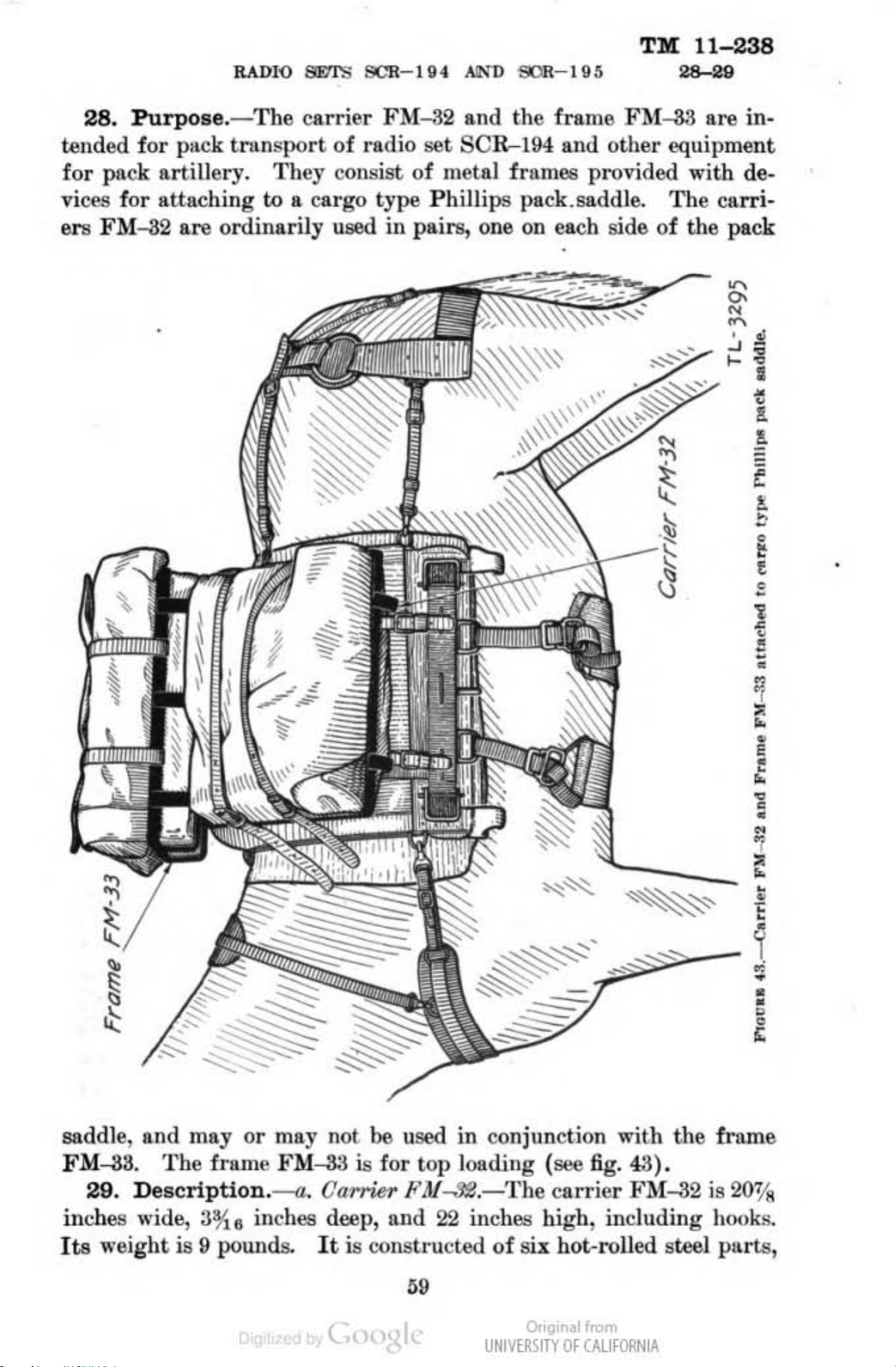
TM
11-238
RADIO
28.
tended for pack
for pack artillery.
vices f
ers
PurposfI
or atta
FM
-32
ching
are o
.-
transport
rd
SVI
'S
SCR- l'i4
The carrier
of
radio
Th
ey
cOJL~is
to
a cargo type
ina rily used
AlN"
D
SOlI-I'i~
FM
-82
!Set
t
of metal frames provided with
ill
pairs, one on each side of
and the frame
SC
R--I94
Phill
ips pack.saddle.
and ot
FM
her
-33
equipment
The carri-
mall
are
th
e peck
in·
de.
~
~
~
"
, ,
" .
" .
•
0
•
!
~
,
-
,
•
-
!
,
,
I
0
•
•
•
•
.,
,
•
• ,
,
•
,
•
"
• ,
x
•
•
,
•
•
saddle, and
FM
-33.
29.
illch
Its weight is
e!l
Th
Description.-a
wide,
ma
yo
e
fnln
3~
II
\I
pounds.
r may not be
e
FM
-33
.
inches deep, alld
is
Carrkr /t',V....1:e
It
is (.'ons
used
for top
tru
"
(
in conjun ction
1000d
22
cted
ing (see fig. 43).
.- T he ca
inch
llll
high, including hooks.
of
six h
UNIVE~\lTY
wi
th
the
rr
ier [.'M-82 is 20%
ol-ro
Of
lled s
CAlifORN
teeJ
IA
i
•
•
•
•
•
•
,
fmm
pllrtll
e
,
Page 61

TlI
11
238
..
•
•
. (
II
60
UNII'(lI<;ITV
•
,
."
Of
C.wfORN
IA
Page 62

TlI[
11-238
RADIO
SETS
SCR-tU
AND
welded together. Two pieces, which form
of
the carrier, are extended and
fit over one
saddle
with
be
obtained
(_
the carrier FM:-32 are items
of the two metal bars along the top
fig.
44).
~
eparately.
The
The
straps
bent
into the shape of hooks, which
and covers which
of
qua~nnaster
arohes and
pack saddle are ordnance issue.
b.
FramtJFM
wide,
pounds.
and 4% inches deep, exclusive
It
-.'J3.-The
is constructed
frameFM-33 i822% inchefllong,
of
mounting feet. I
of
10
hot-rolled steel parts, including mount-
SCR-
part
bolUi
Ult.
of
the back structure
of
the Phillipe pack
are
ordinarily nsed
......
issue and must
for attaching to the
17*
ts
weight
inches
is
12
ing
pins,
frame
manta
it.e
arcl:Jes
rule for t
FM-33. Both are
feet, welded together.
are
ma
30.
provided for attaching the
of
the Phillips pack saddle (see
(cover)
of
quartermaster issue and must be obtllined separately.
and bolts f
whi
ch are ordinarily used with the frame FM-33
or
II.ttaching to the pack saddles are ordnance issue.
Employment.---a.
he
employment
ueed
Four
Uu
of
either the
to
carry parts
bolts, with nuts, washers, and cotter
in
pack "guipmMlt8.-There
frll.m
carrier
e FM-3B to the top
fig.
of
45).
The
FM:-32
radio set
stnp8
is
no
or
the frame
SCR-l94
of
fixed
the
and
are
The
in
various pack equipments, such as the pack equipment CE-{I (also
known
as pack, radio,
and
as pack, radio,
No.2)
pack
equipm
ent
menta CE-{I, CE--7,
No.1),
pack -equipment
, pack equipment
CE-
CE-9
lO
(pack,
and CE-tO,
CE-9
radio,
are
(pack, radio,
No.6).
not
furnished. as such by
CE-7
The
(also known
No.4)
pack equip-
'I
Or
•.•.
UNIVERSITY
Of
1<
..
C/o.lJfORN
lA
Page 63

8l0:.· ... L CORPS
~
<
•
!
•
• ,
•
,
•
•
•
•
•
~
,
•
;,
~
I
~
,
I11111I1
"
•
•
•
f
.,~
UNIVE~IITY
Of
CAlifORN
IA
Page 64

RAJ)IO SETS SCR- I
g4
AND SCR- I
g3
TlII
11-238
......
the Signal Corps but are a
Artillery
for transportation purposes. (See T
rbitrary
groupings used by the pack Field
/BA
No.
6-3, appendix,
for details.)
b.
Loading
.-
The usual method of loading the carrier FM-32 is
as follows :
(1
) Plnce the
(2) Cover the
carrier
carrier
on
the ground, with the open side up.
with a pack cover (manta.), unfolded,
so
that
the cover extends approximately equally beyond the carrier on all
four
rime pushing the cover well down into the
folds
under
sides.
(8) Place the equipment to be loaded into the carrier,
carrier.
(4) Fold Ille pack cover over the equipment, making
if
necessary to take care
(0) Pass
the top
1"1'0
bar
or
more
straps
on each side of the
of
any surplus materilli.
over the top
carrier;
of
pull the
the equipment and
straps
at
the sa
IIddit.i
me
onal
tight
and fasten with the
(6)
",long
the
Lift
the top
carrier,
the loaded
of
(7) Fasten the bottom
of
the saddle by means of straps,
The
vided
The
total load carried in the two carriers FM-32 should be
that
an
equal weight is carried on each side of the pack animal.
frame FM-33 is loaded in a similar manDer to the above.
loading, the frame
a.nd
mounting feet
frame
the four bolts provided are
of
of
the saddl
sUap
carr
buckll!6.
ier,
Ilnd
hang
on
one
of
the two metal bars
the' Phillips pack saddle by means
of
the
i
~
placed
on
the fram e and through the
e.
The washers and nute
carrier
as
shown in figure
the top
P93-ed
to the bottom
of
the Phillipll pack saddle,
through the holes in the
hol
es in the top
are
then placed
of
the hooks on
of
43.
bolts and the nute tightened. The cotter pins provided
paned
thr
ough the holes in the bolts and bent over to prevent
the frame
80
di.
After
of
the
on
the
are
then
loosening
of
the nuts.
SJOrION
BAG BG-82
I'urpDto
~rlpU
EmV1oy""'nL ____________________
31.
the radio set
the
sists
The
______
on
Purpose.
_______ h _ _ _
__
_ _ _____ _ _ _
-
SCR-I94
_____
__________ ______
The
bag
8G---82
by a mounted operator.
weight is carried by the
of
two leather pockets connected togetber by a lesther
yoke fits over the cantle of the McClellan saddle, and one
VIII
P
___
h_h
_______________________________________ 83
__
__
___
___________
h _ ____
__
_ _
_______
__
________________
........
hh_
provides a means for operation
It
is
so
hOr!le
arranged
rather than the operator.
It
that
con·
yoka
68
,
pb
81
82
of
of
Or,~
UNIVERSITY
.•.
Of
1<
..
C/o.lJfORN
lA
Page 65

,
UNIVE~\ITY
OF
CAlifORN
IA
Page 66

TlIf
11-238
31-03
the
included
BA--32
receiver
leather c
AN
in
and
fl
bags fits on each
adapter
32.
one
ap
Description
(fig. 410),
and
ap
-29-B.
end and a
is held in
in
the side
transmitter BC-222 (
is providM in the
An
Si
FT-236
.-The
and the pocket on the oft side carries
adapter
900ltBt
pla
ce
by
of
the radio pocket is
de.
FT
in
The
(battery) is
pocket
top
-236 for battery connection, with a
the
SII
ap fa steners. An opening with a cover
weight of
11
on
the
fig. 47@).
of
the radio pocket for
other, p •
the
pounds.
near side carries the battery
A hole with
..
s between the
provided to make
bag
00
-82 with its
two
set controls accessible. A leather fitting is provided on
the
radio
pocket
is
pr
ovided for storage
H
S-22-
pocket for carryi
on
the
B.
side of the radio pocket opposite the control opening
noth
the radio pocket and the
of
ng
the
the
mi
antenna when
crophone T-24-E and the headset
battery
no
t
pocket
in
use. A small
the
a.
removable
the
radio
antenna
plug
pockets,
the
the
are
radio
top
padded
of
inside with felt, and
itate
of
prevent
installed in
back of
to
the
trees
Usually, however,
Th
depend upon
antenna used.
set is ope rated as a fixed station with
removal
the
33.
the
e range
two pockets, with straps, which are fastened to
them from bouncing.
Employment.
th
proper length for the coil used (see par.
terrain
or
of
bag
e operator.
to
be
low wires with which the antenna may
of
the
the
In
the
the battery. O.rings
BG--82
traveled is open, and often! no obstruction such
it
radio
terrai n and
most c
battery pocket is fitted with a
-
The
is the same as when worn
The
will be necessary
operation
antenna
AN
set SCR-I94 when us
the
n"", it
frequency, as well as the amount
will
strap
are
of
-29-B
to
be
somewhat less than when
utended
provided on
the
radio
may
6),
with good results
use
th
e antenn a collapsed.
ed
in this manner will
antenna.
set
SOR-IM
as
a pack
be
u!led
co
me
the
the
in
to facil-
bottoms
cinch
on
extended
contact . .
to
when
the
if
118
of
the
(
J...
o.
082
.11 (3--3·.·U).]
By
01IDf:H or
oPnC1AL:
J . A. ULIO,
Major General,
Dun'IWIUTION:
R and H 6, 7
(For
upl.&nation
THE
Th
SECRE."I'.utY
~
Adjutant
(3);
IBn
of
symbols
or
GeMTa/,.
6, 1
(6);
WA~
~
"
:
IC
FM
...
G.
C.
11
(6).
21-6.)
....
...
MARSHALL,
OAUI
,," ."."
.....
"
......
of
Staff.
Or
•.•.
UNIVERSITY
Of
1<
..
C/o.lJfORN
lA
 Loading...