


ARMY TM 11-5895-1180-10
NAVY
AIR FORCE
MARINE CORPS
OPERATORS
MANUAL
RADIO SET
EE125-JC-OPl-010/PSC3
31R2-2PSC3-1
TM 5895-10/1
AN/PSC-3
(NSN 5820-01-145-4943)


TM11–5895-1180-10
EE125-JC-OPI-01A/PSC3
TO 31R2-2PSC3-1
TM 5898-10/1
Change
AND HEADQUARTERS, MARINE CORPS
No. 1
DEPARTMENTS OF THE ARMY,
THE NAVY, AND THE AIR FORCE
Washington, DC, 15 January 1992
Operator’s Manual
RADIO SET AN/PSC-3
(NSN 5820-01-1454943) (EIC: L2S)
TM 11-5895-1180-10 / EE125-JC-OPI-010/PSC 3/ TO 31R22PSC3-1 / TM 5895-10/1, 15 February 1988, is changed as
follows:
1. Pen and ink change. On front cover, following NSN, add:
(EIC:L2S).
2. Remove old pages and insert new pages as indicated below. New
or changed material is indicated by a vertical bar in the margin of the
page.
Remove pages
i and ii
1-1 and 1-2
2-5 and 2-8
A-1 through A-4
B-1 through B-4
C-1 and C2
3. File this change sheet in front of the manual for reference
purposes.
Distribution authorized to US Government agencies and their
contractors for official use or for administrative or operational
purposes only. This determination was made on 15 June 1991.
Other requests for this document will be referred to Commander,
US Army Communications-Electronics Command and Fort
Monmouth, ATTN: AMSEL-LC-LM-LT, Fort Monmouth, New
Jersey 07703-5007.
DESTRUCTION NOTICE - Destroy by any method that will prevent
disclosure of contents or reconstruction of the document.
Insert pages
i and ii
1–1 and 1-2
2-5 and 2-6
A–1 through A-4
B-1 through B-4
C-1 and C–2

By Order of the Secretary of the Army:
Official:
GORDON R. SULLIVAN
MILTON H. HAMILTON
Administrative Assistant to the
Secretary of the Army
00297
By Order of the Marine Corps:
H. E. REESE
Deputy for Support
Marine Corps Research
Development and Acquisition
Command
By Order of the Secretary of the Navy:
ROBERT AILES
Rear Admiral, United States Navy
Command, Space and Naval Warfare
Systems Command
By Order of the Secretary of the Air Force:
LARRY D. WELSH
General, United States Air Force
Chief of Staff
Official:
CHARLES D. McDONALD
General, United States Air Force
Commander, Air Force
Logistics Command
Distribution:
To be distributed in accordance with DA Form 12-51-E,
block 1587, Operator Maintenance requirements for
TM 11-5895-1180-10.

WARNING
ELECTROMAGNETIC RADIATION
Do NOT stand in direct path of the Medium Gain Antenna
when power is on. Do NOT work on cables while power is on.
Transmit antenna cables conduct radio frequency energy that
can cause fatal internal burns and electrical shock. Ensure that
power is off before working on antenna or connectors. If you
feel a slight warming effect while near this equipment, MOVE
AWAY QUICKLY!
CLEANING
Adequate ventilation should be provided while using TRlCHLOROTRIFLUOROETHANE.
vapor should be avoided. The solvent should not be used near
heat or open flame, the products of decomposition are toxic
and irritating.
dissolves natural oils, prolonged contact with skin should be
avoided. When necessary, use gloves which the solvent cannot
penetrate. If the solvent is taken internally, consult a physician
immediately.
Compressed air shall not be used for cleaning purposes except
where reduced to less than 29 pounds per square inch (psi)
and then only with effective chip guarding and personnel
protective equipment. Do not use compressed air to dry parts
when TRICHLOROTRIFLUOROETHANE has been used.
Compressed air is dangerous and can cause serious bodily harm
if protective means or methods are not observed to prevent
chips or particles (of whatever size) from being blown into the
eyes or unbroken skin of the operator or other personnel.
Since TRICHLOROTRIFLUOROETHANE
Prolonged breathing of
BLACKOUT
When operating Radio Set AN/PSC-3 in enemy territory, bright
lights will make it easy for the enemy to detect your presence.
Use blackout procedures to prevent detection by the enemy.
A

SAFETY STEPS TO FOLLOW IF
SOMEONE IS THE VICTIM OF
ELECTRICAL SHOCK
DO NOT TRY TO PULL OR GRAB THE
INDIVIDUAL
IF POSSIBLE, TURN OFF THE ELECTRICAL
POWER
IF YOU CANNOT TURN OFF THE ELECTRICAL POWER, PULL, PUSH, OR LIFT
THE PERSON TO SAFETY USING A DRY
WOODEN POLE OR A DRY ROPE OR
SOME OTHER INSULATING MATERIAL
SEND FOR HELP AS SOON AS POSSIBLE
AFTER THE INJURED PERSON IS FREE
OF CONTACT WITH THE SOURCE OF
ELECTRICAL SHOCK, MOVE THE PERSON
A SHORT DISTANCE AWAY AND
IMMEDIATELY START ARTIFICIAL
RESUSCITATION
B

HIGH VOLTAGE
is used in the operation of this equipment
DEATH ON CONTACT
may result if personnel fail to observe safety precautions.
Never work on electronic equipment unless there is another
person nearby who is familiar with the operation and hazards
of the equipment and who is competent in administering first
aid. When technicians are aided by operators. they must be
warned about dangerous areas.
Whenever possible, the power supply to the equipment must be
shut off before beginning work on the equipment. Take particular care to ground every capacitor likely to hold a dangerous
potential. When working inside the equipment, after the power
has been turned off, always ground every part before touching
it.
Be careful not to contact high-voltage connections or 115 volt
ac input connections when installing or operating this equipment.
Whenever the nature of the operation permits, keep one hand
away from the equipment to reduce the hazard of current
flowing through the body.
WARNING:
DO NOT BE MISLED BY THE TERM “LOW
VOLTAGE.” POTENTIALS AS LOW AS 50
VOLTS MAY CAUSE DEATH UNDER
ADVERSE CONDITIONS.
For Artificial Respiration, refer to FM 21-11.
c

WARNING
A lithium-sulfur dioxide (Li-SO2) battery used with the
RT-1402A/G contains pressurized sulfur dioxide (SO2) gas. The
gas is toxic, and the battery MUST NOT be abused in any way
which may cause the battery to rupture.
Do not heat, short circuit, crush, puncture, mutilate, or
disassemble batteries.
Do not use any battery which shows signs of damage, such
as bulging, swelling, disfigurement, brown liquid in the plastic
wrap, a swollen plastic wrap, etc.
Do not test Li-SO2 batteries for capacity,
Do not recharge Li-SO2 batteries.
Do not use water to extinguish Li-SO2 battery fires if a shock
hazard exists due to high voltage electrical equipment in the
immediate vicinity (i.e., greater than 30 volts, alternating
current (ac) or direct current (dc)).
If the battery compartment becomes hot to the touch, if
you hear a hissing sound (i.e., battery venting), or smell
irritating sulfur dioxide gas, IMMEDIATELY turn OFF the
equipment. Remove the equipment to a well ventilated
area or leave the area.
Do not use a HaIon type fire extinguisher on a lithium battery
fire.
In the event of a fire, near a lithium battery(ies), rapid cooling
of the battery(ies) is important. Use a carbon dioxide (CO2)
extinguisher. Control of the equipment fire, and cooling, may
prevent the battery from venting and potentially exposing
lithium metal. In the event that lithium metal becomes
involved in fire, the use of a graphite based Class D fire
extinguisher is recommended, such as Lith-X or MET-L-X,
Do not store lithium batteries with other hazardous materials
and keep them away from open flame or heat.
D
-
.

TM 11-5895-1180-10
Technical Manual
No. 11-5895-1180-10
Technical Manual
No. EE125-JC-OPI-01A/PSC3
Technical Order
No. 31R2-2PSC3-1
Technical Manual
. No. 5895-10/1
OPERATOR’S MANUAL
RADIO SET AN/PSC-3
(NSN 5820-01-145-4943) (EIC:L2S)
EE125-JC-OPl-01A/PSC-3
DEPARTMENTS OF THE ARMY,
THE NAVY, THE AIR FORCE,
AND HEADQUARTERS,
Washington, DC, 15 February 1988
31R2-2PSC3-1
TM 5895-10/1
MARINE CORPS
REPORTING ERRORS AND
RECOMMENDING IMPROVEMENTS
You can help improve this manual. If you find any mistakes or if you know of a way to improve the procedures,
please let us know. Mail our letter, DA Form 2028 (Recommended Changes to Publications and Blank Forms),
or DA Form 2028-2, direct to: Commander, US Army
Communications-Electronics Command and Fort Monmouth, ATTN: AMSEL-LC-LM-LT, Fort Monmouth, New
Jersey 07703-5007.
For Air Force, submit AFTO Form 22 (Technical Order
System Publication Improvement Report and Reply) in
accordance with paragraph 6-5, Section VI, T.O.
00-5-1. Forward direct to prime ALC/MST.
For Navy, mail comments to the Commander, Space and
Naval Warfare Systems Command, ATTN:
PAWAR
S
8122, Washington, DC, 20363-5100.
Marine Corps units, submit NAVMC 10772 (Recom-
mended Changes to Technical Publications) to: Commanding General, Marine Corps Logistics Base (Code
850), Albany, Georgia 31704-5000.
In any case a reply will be furnished direct to you.
Change 1 i

PAGE
HOW TO USE THIS MANUAL
CHAPTER 1. INTRODUCTION . . . . . . . 1-1
Section I. General Information . . 1-1
Section II. Equipment Description and Data]. 1-6
Section III. Technical Principles of Operation . 1-17
CHAPTER 2.
OPERATING INSTRUCTIONS
. . . . . . 2-1
ii
Section I.
CHAPTER 3. MAINTENANCE INSTRUCTIONS
Description and Use of Operator
. . .
Preventive Maintenance Checks and
II.
. . .
III.
Operation Under Usual Conditions . .
IV. Operation Under Unusual Conditions
. . .
. . .2-72
. . . . 3-1
2-1
2-10
2-16
Section I. Troubleshooting Procedures . . . . . . . . 3-1
II. Maintenance Procedures . . . . . . . . . . . 3-6
APPENDIX A.
REFERENCES . . . . . . . . . . . . . .A-1
B.
COMPONENTS OF END ITEM
AND BASIC ISSUE ITEMS LISTS . . . B-1
ADDITIONAL AUTHORIZATION
c.
LIST . . . . . . . . . . . . . . . . . . . .C-1
D.
EXPENDABLE SUPPLIES AND
MATERIALS LIST . . . . . . . . . . . D-1
HOW TO USE THIS MANUAL
This manual is divided into three chapters.
● CHAPTER 1 contains an
introduction to this manual
with functional and physical description of Radio Set
AN/PSC-3. Full view illustrations are provided to assist you
in major component identification.
ii

. CHAPTER 2 contains the description and use of operator
controls with supporting illustrations, instructions for
operation under usual and unusual conditions, and a table
of preventive maintenance checks and senvices.
. CHAPTER 3 contains maintenance data. It provides
operator troubleshooting procedures, maintenance procedures, and operator maintenance limitations for Radio Set
AN/PSC-3.
Pages are numbered consecutively throughout the manual.
.
Each chapter is divided into sections and sections into para-
graphs. Certain section titles are boxed on the front cover. At
the right edge of each box is a blackened area. This blackened
area matches a black mark appearing on the first page of that
section in the manual.
iii

1-0
RADIO SET AN/PSC-3 COMPONENTS

CHAPTER 1
INTRODUCTION
PAGE
General Information . . . . . . . . . . . . . . . . . . . . . . . . . . . . . . . ...1-1
Equipment Description and Data.. . . . . . . . . . . . . . . . . . . . . ...1-6
Technical Principles of Operation. . . . . . . . . . . . . . . . . . . . . ..1–17
Section I
GENERAL INFORMATION
1-1. SCOPE
This manual is for your use in operating Radio Set AN/PSC-3. In
addition to detailed operating procedures, the manual will assist
you in setting up for Iine-of-sight (LOS), satellite relay (SAT) and
retransmit (XMT) operation. twill also provide you with operator
maintenance.
1-2. MAINTENANCE FORMS, RECORDS, AND REPORTS
a. Reports of Maintenance and Unsatisfactory Equipment. Department of the Army forms and procedures used for equipment
maintenance will be those prescribed by DA Pam 736-750, as
contained in Maintenance Management Update. Air Force ersonnel will use AFR 66-1 for maintenance reporting and TO00-35D54 for unsatisfactory equipment reporting. Navy personnel will report maintenance performed utilizing the Maintenance
Data Collection Subsystem (MDCS) IAW OPNAVINST 4790.2,
Vol 3 and unsatisfactory material/conditions (UR submissions)
IAW OPNAVINST 4790.2, Vol 2, chapter 17. Marine Corps maintains forms and procedures as prescribed byTM 4700-15/1.
Change 1 1–1

b. Report of Packaging and Handling Deficiencies. Fill out and
forward SF 364 (Report of Discrepancy (ROD)) as prescribed in
AR 735-11-2/DLAR 4140.55/SECNAVlNST 4355.18/AFR
400-54/MCO4430.3J.
c. Transportation Discrepancy Report (TDF) (SF 361). Fill out
and forward Transportation Discrepancy Report (TDR) (SF 361)
as prescribed in AR 55–38/NAVSUPlNST 4610.33C/AFR
75–18/MCOP4610.19D/DLAR 4500.15.
1-3. HAND RECEIPT (-HR) MANUALS
This manual has a companion document with a TM number followed by “-HR” (which stands for Hand Receipt). The TM
11-5895-1180-1 0-HR consists of preprinted hand receipts (DA
Form 2062) that list end item related equipment (i.e., COEI, Bll,
and AAL) you must account for. As an aid to property accountability, additional –HR manuals may be requisitioned from the US
Army Adjutant General Publications Center, Baltimore, MD, in accordance with the procedures in Chapter 3, AR 310–2, and DA
Pam 310-10.
1-4. REPORTING EQUIPMENT IMPROVEMENT RECOMMENDATIONS (EIR)
a. Army. If your AN/PSC-3 needs improvement, let us know.
Send us an EIR. You, the user, are the only one who can tell us
what you don’t like about your equipment. Let us know why you
don’t Iike the design or performance. Put it on an SF 368 (Product
Quality Deficiency Report). Mail it to: Commander, US Army
Communications-Electronics Command and Fort Monmouth,
ATTN:
AMSEL-ED–PH, Fort Monmouth, New Jersey
07703-5007. We’ll send you a reply.
b. Air Force. Air Force Personnel are encouraged to submit
ElR’s in accordance with AFR 900-4.
c. Navy. Navy personnel are encouraged to submit ElR’s
through their Iocal beneficial Suggestion Program.
d. Marine Corps Users. QDR shall be reported on SF 368 in ac-
cordance with MCO 1650.17, Quality Deficiency Report Manual.
Submit to Commanding General, Marine Corps Logistics Base
(Code 856), Albany, Georgia 31704-5000.
1–2 Change 1

1-5. NOMENCLATURE CROSS-REFERENCE LIST
The following list should help you locate the official nomenclature of compone
nts of/or equipment used with Radio Set
AN/PSC-3. Official nomenclature must be used when
completing report forms or when looking up technical
manuals.
COMMON NAME
ALICE Pack
OFFICIAL NOMENCLATURE
All-Purpose Lightweight Individual
Carrying Equipment
Backpack Radio Set
Battery Box
DMDG
Radio Set AN/PSC-3
Battery Box CY-8006/PSC-3
Digital Message Device Group
OA-8990/P
Handset
Handset H-250( )/U
Medium Gain
Antenna
Antenna AS-3567/G
Net Control Station
or NCS
-
R/T Unit
RXMT Cable
Whip Antenna
Radio Set AN/VSC-7
Receiver/Transmitter RT-1402A/G
Retransmission Cable MK-456/GRC
Antenna AS-3566/G
1-6. LIST OF ABBREVIATIONS AND ACRONYMS
A complete list of all abbreviations and acronyms used in this
manual are listed below.
ANT
bps
BPSK
CAL
CON
cc w
CT
cw
dB
DBPSK
Antenna
bits per second
Bi-Phase Shift Keying
Call
Conference
counterclockwise
Cipher Text
clockwise
Decibel
Differential Coding Bi-Phase Shift Keying
1-3

LIST OF ABBREVIATIONS AND ACRONYMS (cont)
dc
FM
FM-FSK
Hz
kbps
kHz
LOS
MHz
Ni-Cad
PMCS
PSK
PTT
RCV or
REC
RF
RXMT
SAT
SEL
UHF
U/M
v
VSWR
XMIT or
XMT
XMTR
1-7. GLOSSARY
ALPHANUMERIC - A set of characters containing both letters,
numbers and other symbols.
AMP-HOUR - Ampere-hour is a current of one ampere flowing
for one hour.
AUDIO - Frequencies that are heard.
BANDWIDTH - The difference in hertz between the highest
and lowest frequency required for adequate signal transmission.
BURST MODE - Used in DATA mode. Transmitting or receiving data traffic at a high rate of speed in short bursts.
1-4
direct current
Frequency Modulation
Frequency Modulation - Frequency Shift Keying
Hertz
kilo bits per second
kilo Hertz
Line-of-Sight
Mega Hertz
Nickel-Cadmium Cell
Preventive Maintenance Checks and Services
Phase Shift Keying
Push To Talk
Receive
Radio Frequency
Retransmit
Satellite Relay
Selective
Ultra High Frequency
Unit of Measure
Volts
Voltage Standing Wave Ratio
Transmit
Transmitter

CHANNEL SPACING - The Frequency band in hertz between
two channels.
DETUNE - To change the inductance and/or capacitance of a
tuned circuit, causing it to be resonant at other than the
desired frequency.
ENCRYPTION - To convert from ordinary language into ci-
pher or code.
INTERFACE - Connecting and making two pieces of equip-
ment compatible.
JAMMING Transmitted signals intended to interfere with the
reception of signals from another station.
LINE-OF-SIGHT (LOS) - A straight line between communica-
tion networks.
OMNIDIRECTIONAL - All directional, not favoring any one
direction.
RETRANSMIT (RXMT) - The transmission of information
received from a previous transmission.
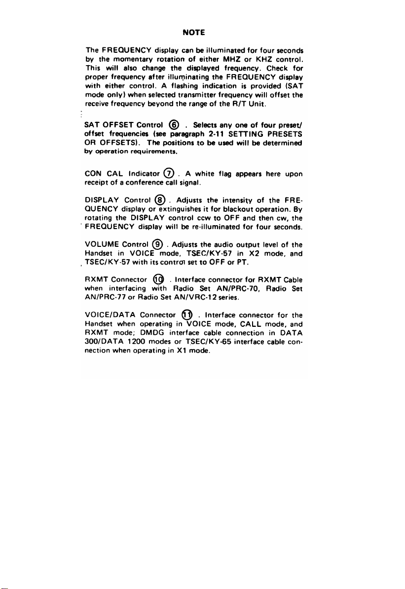
SAT OFFSET - The transmitter of a transceiver transmitting
on one frequency while the receiver is receiving on a different
preset offset frequency. The offset frequency is referenced to
the transmit (dial) frequency of Radio Set AN/PSC-3.
EXAMPLE: Dial Frequency is 305.265 MHz, selected off-
set is 30.750 MHz, actual receive for the
selected offset is 305.265 - 30.750 = 274.515
MHz.
SATELLITE RELAY (SAT) - A signal transmitted to a satellite
relay station at one frequency with the satellite relay station
retransmitting the same data to distant stations. The satellite
transmitted signal will be at a different frequency than the fre-
quency received by the satellite.
1-5

Section II
EQUIPMENT DESCRIPTION AND DATA
1-8. PURPOSE
Radio Set AN/PSC-3 is a portable, battery operated, half dup
Iex UHF transceiver. It provides two-way voice (secure and
plain) and data communication via satellite relay (SAT) or lineof-sight (LOS) modes. It operates in the UHF frequency band
of 225 MHz to 399.995 MHz range. Radio Set AN/PSC-3 is
hereinafter referred to as the Backpack Radio Set. One operator is required to crew and operate it. For mobile operation it
is harnessed to the back of the operator. For at halt operation,
it is ground positioned by the operator.
Performance margins permit the use of an omnidirectional low-
gain whip antenna for reception of selective and/or conference
calls from a satellite relay station and for reception and trans-
mission of LOS signals. A directional, medium gain, tripod
mounted antenna is used for SAT operation.
Retransmit (RXMT) operation is possible using Radio Set
AN/PRC-70, Radio Set AN/PRC-77 or Radio Set AN/V RC-12
series with Retransmission Cable MK-456/GRC. The equip-
ment must be separated 25 to 100 feet to prevent interference.
1-9. CAPABILITIES AND FEATURES
a.
The receiver portion and transmitter portion of the
R/T Unit each operate over the identical UHF frequency range of 225 to 399.995 MHz.
b.
Transmitter Output:
● 27.8 Watts in SAT mode of operation with a
medium gain antenna deployed.
● 2 Watts in LOS mode of operation with the low-
gain whip antenna deployed.
1-6

c.
Channel Spacing:
● 5 kHz increments for SAT mode of operation.
● 25 kHz increments for LOS mode of operation.
d. It is capable of receiving and transmitting in any one
of the following modes in both SAT or LOS mode of
operation.
● VOICE - Plain voice audio is standard analog FM
using Handset H-250( )/U. This mode will allow
direct communication with other types of UHF
radios particularly the AN/WSC-3(VI), PRT25067, and AN/URC-101.
● X modes -
It will interface with either the TSEC/
KY-57 or TSEC/KY-65 security devices:
-X1 - TSEC/KY-65 for standard analog FM secure
voice operation.
-X2 - TSEC/KY-57 for 16 kbps (FM-FSK) wideband digital secure voice or TSEC/KY-57 standard
analog FM plain voice in PT or OFF positions of
TSEC/KY-57.
● RXMT - Retransmit mode is either plain voice or
TSEC/KY-65 secure voice standard analog FM. Retransmit mode is compatible with Radio Sets AN/
PRC-70, AN/PRC-77 and AN/VRC-12 series when
using Retransmission Cable MK-456/GRC.
NOTE
CALL mode operation is a unique calling function. It allows
the sending station to alert a distant unit with a visual white
flag indication, and if desired, a five second audible alarm.
● CALL - It will receive conference calls and one of
15 individual selective calls or transmit conference
calls. BPSK modulation is used in both transmit
and receive modes.
1-7

● DATA - It will interface with Digital Message
Device Group OA-8990/P at 300/1200 bps. The
2400 mode will interface with other MIL-STD188C low level data devices at 2400 bps.
1-10. LOCATION AND DESCRIPTION OF MAJOR
COMPONENTS
The Backpack Radio Set can be configured for the
a.
SAT or LOS mode. The major components for SAT
mode are Receiver/Transmitter RT-1402A/G, Battery
Box CY-8006/PSC-3, and Antenna AS-3567/G. The
primary components for operation are keyed in the
following illustration.
SAT CONFIGURATION – MAJOR COMPONENTS
1-8

1-9

b.
The Backpack Radio Set can be configured for the
LOS mode. The major components for LOS configuration are the R/T Unit, Battery Box, and Antenna
AS-3566/G. The primary components necessary for
operation are keyed in the following illustration.
1-10

d.
Tactical Speech Security Equipment TSEC/KY-65. An
analog voice frequency system which provides half duplex, tactical secure voice communications when
used with compatible radio sets, integrated wire/
multichannel radio systems or tactical/commercial
wireline systems.
Radio Set AN/PRC-77. A short-range, 920 channel,
e.
manpack, FM communication equipment, operating in
the frequency range of 30 to 75.95 MHz inclusive in
increments of 50 kHz.
f.
Radio Set AN/PRC-70. A manpack multimode (FM,
CW, FSK, SSB, AM) communication equipment
operating in the frequency range 2 to 75.9999 MHz.
Radio Set AN/VRC-12 series. A vehicular, medium
g.
range, two-way radio-telephone communications set
operating in the 30 to 75.95 MHz frequency range.
Power Supply PP-6148/U. Used to charge Ni-Cad 24
h.
volt batteries or to power the Backpack Radio Set.
The power supply provides a nominal output voltage
of either 14 V dc or 28 V dc, at currents up to 10
amperes, where available ac power is either 115 V or
230 V single phase 50, 60 or 400 Hz. The output
voltage is continuously adjustable within a range of
approximately 12 to 16 V dc or 24 to 32 V dc
according to the nominal voltage selected. Output
current limiting is selectable in five ranges from 0.5 to
10.0 amperes, and is adjustable within the four ranges
from 0.5 to 8.0 amperes.
i.
Generator, Direct Current G-76/G. The dc generator
is a portable hand-cranked electrical generator with
accessories to provide power to military radios, coding
equipment, rechargeable batteries, and other electronic
equipment in the field.
Digital Message Device Group OA-8990/P. Referred to
j.
hereinafter as the DMDG is a handheld, self-contained
unit providing a means to enter and retrieve digital
alphanumeric information in a free format style.
1-13

1-12. EQUIPMENT INTEROPERABLE WITH THE BACK-
PACK RADIO SET
a.
Satellite Communication Set AN/WSC-3(VI), cornmonly referred to as the Whiskey Three. The Whiskey
Three is a highly flexible, new generation, ship/submarine UHF (225 to 399.995 MHz) SAT/LOS communications terminal which sends and receives AM/
FM or data information. The Whiskey Three has a
minimum of 100 watts output in FM or data modes. It
features internal modulation and detection for 75 bps
FSK or 75 bps to 9600 bps PSK. A 70 MHz interface
capability is provided for expansion with a variety of
external modems.
Radio Set AN/VSC-7. Referred to hereinafter as the
b.
Net Control Station or NCS is described in paragraph
1-1 lb, page 1-12.
Radio Set PRT-250B7. A portable satellite AM and
c.
FM communication system consisting of a transceiver,
control unit, battery pack, VHF and UHF antenna,
and a handset which provides the primary link be-
tween the operator and the radio set. The transceiver
operates in the 116 to 150 MHz VHF band and 225 to
399.995 MHz UHF band, tunable in 25 kHz incre-
ments. The transmitter portion delivers 20 or 5 watts
in the UHF band. The set is designed for manpack,
vehicular and aircraft application, and has the TSEC/
KY-65 and TSEC/KY-57 interface capability for
secure operation. The PRT-250B7 is interoperable
with the Backpack Radio Sat in VOICE, X MODE,
and RXMT modes only.
1-14

LOS CONFIGURATION - MAJOR COMPONENTS
1-11

1-11. EQUIPMENT USED IN CONJUNCTION WITH THE
BACKPACK RADIO SET
All-Purpose Lightweight Individual Carrying Equip-
a.
ment. This carrying equipment will hereinafter be
referred to as the ALICE Pack. The Backpack Radio
Set (R/T Unit with Battery Box attached) will be
placed in the inside pocket of the large combat field
pack. Detailed information for the ALICE Pack can be
obtained from Field Manual FM 21-15. The ALICE
Pack is an Additional Authorization List (AAL) item.
b.
Control-Converter C-11119A/VSC-7. Referred to hereinafter as NCS Applique, is a one-piece assembly that
provides base stat ion capabilities when interfaced with
the Backpack Radio Set R/T Unit to configure Radio
Set AN/VSC-7. In addition to providing the physical
mount, the NCS Applique also provides:
● Input power conditioning
● 27.8 watt output
● Automatic T/R changeover
● Transmit and receive selective calling
● EMI protection against other nearby transmitters
● Continuous keydown operation
The NCS Applique permits the R/T Unit to be
powered by the vehicular power system in use, i.e.,
+24 V in a vehicle or 110/220 V at 50/60 cycles in a
communications shelter.
Tactical Speech Security Equipment TSEC/KY-57.
c.
A small, lightweight, manpack, battery operated, wideband secure voice digital communications equipment
designed for use with FM and AM and VHF and UHF
radio communications and wireline systems.
It is a
half-duplex, push-to-talk equipment operating at a
16,000 bits per second (bps) rate. The battery and
battery case (Z-A1J) may be replaced by an HYP-57
Vehicular Power Supply and be operated in a vehicular
configuration with appropriate installation kit.
1-12

1-13. EQUIPMENT DATA
1-15

1-16
TECHNICAL DATA

Section III
TECHNICAL PRINCIPLES OF OPERATION
1-14. GENERAL
The following paragraphs describe the basic principles of operation of the Backpack Radio Set. The LOS mode of operation
is discussed first. SAT mode of operation and RX MT operation are illustrated and will be discussed separately.
1-15. LOS MODE OF OPERATION
LOS mode of operation allows the Backpack Radio Set to be
transported by one person on foot or in a vehicle. With an assigned monitoring frequency (according to operation requirements) for LOS mode, you may continue in motion with the
R/T Unit in a condition to receive a selective or conference
calling signal. The reception of a selective calling signal will
execute a SEL CAL white flag and a five second 1 kHz contin-
uous audible alarm. Reception of a conference calling signal
will execute a CON CAL white flag and a 1 kHz audible alarm
switched on and off at a 1 Hz rate of five seconds. In LOS
mode, the R/T Unit will transmit and receive on the frequency
appearing in the FREQUENCY display. A basic LOS transmis-
sion scheme as illustrated consists of the following:
1-17

1-16. RXMT OPERATION
1-18

1-19

1-17. SAT MODE OF OPERATION
SAT mode of operation provides a satellite link between Backpack Radio Sets and/or a Net Control Station. The Net Control
Station may be installed in a communication shelter or vehicle.
In SAT mode, the R/T Unit receive frequency will be OFFSET
from the transmit frequency (appearing in FREQUENCY
display) by the position of the SAT OFFSET control. Using
the following illustration, a satellite relay scheme consists of
the following:
1-20

CHAPTER 2
OPERATING INSTRUCTIONS
Page
Description and Use of Operator Controls
and Indicators . . . . . . . . . . . . . . . . . . . . . . . ..2-1
Preventive Maintenance Checks and Services . . . . . . . . 2-10
Operation Under Usual Conditions . . . . . . . . . . . . . .2-16
Operation Under Unusual Conditions . . . . . . . . . . . .2-72
Section I
DESCRIPTION AND USE OF OPERATOR
CONTROLS AND INDICATORS
2-1. GENERAL
This section Provides a general description of operator controls, indicators, and connectors. It will list their functions,
operator actions, and provide illustrations to determine their
locations. All operator controls and indicators are located on
the R/T Unit front panel with the exception of the Variable
Power control (XMT PWR ), which is located on the side of
the R/T Unit. Connectors are located on the front and rear
panels of the R/T Unit. Section III and Section IV of this
chapter present specific instructions for use during usual
and unusual operating conditions:
2-1

2-2. R/T UNIT CONTROLS AND INDICATORS
2-2

ANT Connector ➀ Connector for the Whip Antenna in LOS
mode and Medium Gain Antenna cable in SAT mode.
MODE Control ➁ .
Selects one of eight communication
modes.
●
X1 - Selects interface operation with the TSEC/KY-65
encryption device for standard narrowband analog FM
secure voice communication and is used in preset
loading.
●
X2 - Selects interface operation with the TSEC/KY-57
encryption device for wideband (16 kbps FM-FSK)
secure voice digital communications or standard analog
FM plain text communication and is used in preset
loading.
●
RX MT - Selects retransmit operation with Radio Set
AN/PRC-70, AN/PRC-77 and AN/VRC-12 series.
●
VOICE - Selects voice mode (plain voice) and used only
with a Handset.
●
CALL - Selects call mode of operation, used in conjunction with CALL control ➃ .
●
DATA 300- Selects operation for low level data equipment, continuous or burst (DMDG) at 300 bps.
●
DATA 1200 - Selects interface operation for low level
data equipment, continuous or burst (DMDG) at 1200
bps.
●
2400 - Selects interface operation with other MIL-STD-
188C low level data equipment at 2400 bps.
SEL CAL Indicator ➂ .
Black and white ball, referred to
hereinafter as a white flag, pivots to white upon receipt of a
selective call signal.
CALL Control ➃ . Selects any one of four functions. Used in
conjunction with MODE control ➁ . Functions only when
MODE control is set to the CALL position.
● SEND - This is a spring-loaded, momentary position.
Initiates the transmission of the one minute conference
call signal. This position is also used in preset loading.
● RCV - Provides for reception of a selective or confer-
ence call signal as follows:
2-3

Visual - The SEL CAL white flag wiII indicate the
reception of a selective call, The CON CAL white
flag wiII Indicate the reception of a conference call.
Audible - The audible alarm concealed behind the
front panel wiII sound continuously for five seconds
for an incoming selective call and intermittently for
an incoming conference call.
● QUIET The audible alarm wiII not sound upon recep-
tion of a call signal. The visual white flag indicators wiII
operate normally.
● RESET - This is a spring-loaded momentary position.
The RESET position wiII stop the one minute confer
ence call transmission before allotted time of one minute and one minute time-out upon reception of a call
RESET wiII also reset SEL CAL and CON CAL visual
indicator flags.
FREQUENCY Display Indicator ➄ . This is a six digit electronic frequency readout and functions as follows:
● Displays transmitter and receiver frequency when oper-
ating in LOS mode.
● Displays only transmitter frequency when operating in
SAT mode.
● Remains illuminated for four seconds after frequency
selection. It may be re-illuminated for four seconds by
the MHZ, KHZ, or DISPLAY controls.
2-4
2-5

2-6 Change 1

2-7

2-8

2-9

Section II
PREVENTIVE MAINTENANCE
CHECKS AND SERVICES
2-3. GENERAL
To ensure that the Backpack Radio Set is always ready for use
you must do scheduled PREVENTIVE MAINTENANCE
CHECKS AND SERVICES (PMCS).
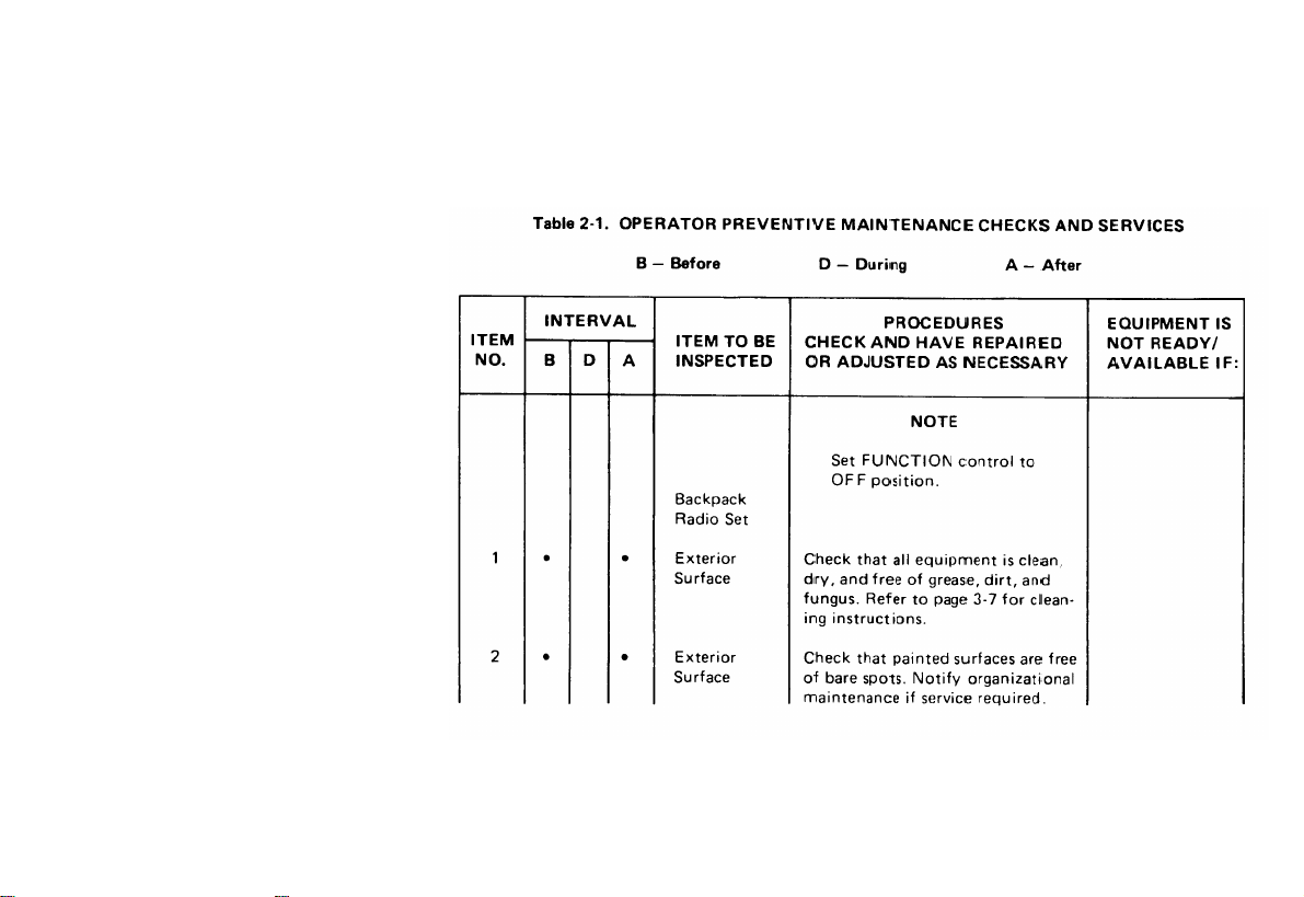
2-4. PMCS TABLE
WHEN YOU ARE DOING ANY PMCS OR ROUTINE
CHECKS, KEEP IN MIND THE WARNINGS AND CAUTIONS SHOWN IN THIS MANUAL.
A dot in one or more of the three INTERVAL columns indicates the check and/or service should be performed as follows:
The PROCEDURES column tells you how to perform the re-
quired checks and services. Carefully follow these instructions.
If tools are needed or the chart tells you (EQUIPMENT IS
NOT READY/AVAILABLE IF:), notify organizational maintenance.
If the Backpack Radio Set fails to operate, refer to Maintenance Instructions in chapter 3.
proper forms in accordance with
2-10
Report any deficiencies using
DA Pam 738-750.

25. ROUTINE CHECKS
Routine checks (equipment
checking for frayed cables, storing items not in use, and
checking loose nuts) are not listed as PMCS checks. They are
things you should do anytime you see they must be done.
inventory, cleaning, dusting,
2-11
2-12
Table 2-1. OPERATOR PREVENTIVE MAINTENANCE CHECKS AND SERVICES

2-13
TABLE 2-1. OPERATOR PREVENTIVE MAINTENANCE CHECKS AND SERVICES (cont)

2-14
Table 2-1. OPERATOR PREVENTIVE MAINTENANCE CHECKS AND SERVICES (cont)

2-15
Table 2-1. OPERATOR PREVENTION MAINTENANCE CHECKS AND SERVICES (cont)

Section III
OPERATION UNDER USUAL CONDITIONS
2-6. GENERAL
The Backpack Radio Set can be operated in the mobile (strapped to your back) configuration or in the at halt (stationary) configuration. Setup procedures are given in three parts -
LOS operation, SAT operation, and RXMT operation. Operating procedures are provided for all modes in both transmit and
receive. Complete shutdown procedures are also provided in
this section. You must be aware of operation requirements
prior to operating this equipment in the field.
2-7. LOS OPERATION SETUP
This setup allows the Backpack Radio Set to be transported by
one person on foot or in a vehicle.
2-16

2-17

CONTROL
SETTING
FUNCTION . . . . . . . .
MODE . . . . . . . . . . .
MHZ/KHZ . . . . . . .
CALL. . . . . . . . .
XMT PWR . . . . . . . . . . . .
STEP
Proceed to operating procedures (page 2-39) for desired
7
operating.mode according to operation requirements
2-18
LOS
According to operation
requirements.
According to operation
requirements.
According to operation
requirements.
Full-up (extreme cw) or
according to operation
requirements.
STEP
Secure strap across
5
front panel of R/T Unit
and mount assembled
ALICE Pack on your
shoulders. Adjust and
secure all straps. For
additional ALICE Pack
Information, refer to
field manual FM 21-15.
STEP
Store Medium Gain
6
Antenna according to
operation requirements.

2-8. SAT OPERATION SETUP
2-19

2-20
WARNING

2-21

STEP
Proceed to operating procedures (page 2-39) for
12
desired operating mode according to operation
requirements.
2-22

2-9. RXMT OPERATION SETUP
STEP
Setup for SAT operation (page 2-19, Step 1 thru Step 11)
1
or LOS operation (page 2-16, Step 1 thru Step 3).
STEP
If permitted by operation requirements, establish SAT or
2
LOS capability by performing the following operating
procedures:
● CALL mode - Transmit (page 2-40).
● CALL mode - Receive (page 2-43).
● VOICE mode - Transmit (page 2-58).
● VOICE mode - Receive (page 2-61).
2-23

2-24

When interfacing with TSEC/KY-57 or TSEC/KY-65, refer to
page 2-68.
2-25

STEP
Proceed to RXMT operating procedures (page 2-56).
12
2-10.
INITIAL ADJUSTMENTS, DAILY CHECKS AND
OPERATIONAL TEST
The Backpack Radio Set requires no adjustments at the operator level. Your daily check will consist of PMCS Table 2-1
(page 2-12) and operational test of the complete unit. Take a
known good Backpack Radio Set and the Backpack Radio Set
you will be using, refer to page 2-16, and setup as illustrated on
following page.
2-26

refer to page 3-1
For additional information for VOICE mode of operation,
refer to page 2-58.
2-27

2-11. SETTING PRESETS OR OFFSETS
The AN/PSC-3 provides the operator with the capability of
selecting up to 4 frequencies (LOS mode) or 4 frequency
off sets (SAT mode) and presetting the manpack so that any
of the preset frequencies or offsets may be immediately selected using the OFFSET control on the RT-1402A/G Front Panel.
In the SAT mode, an uplink (transmit) frequency and a downIink (receive) frequency are preset for each OFFSET position,
thus establishing the transmit/receive offsets. The FREQUENCY DISPLAY will indicate only the transmit frequency
during actual operation.
transmit and receive frequency is used, the same procedure
es used in SAT mode is followed except that identical transmit and receive frequencies are preset for a given OFFSET
control position and the frequency offset is thus zero.
PRESET LOADING
2-12.
STEP
Set RT-1402A/G controls as follows:
I
In LOS operation where the same
2-28

2-29

2-30
2-31

2-32

2-13. PRESET REVIEW
2-33

2-14. PRESET CLEARING
2-34

NOTE
When the CALL Switch is released (allowed to return to RCV),
the FREQUENCY Display will be blank.
NOTE
At this point, the uplink (transmit) preset has been cleared
but the current downlink (receive) frequency preset and the
original frequency off sat have not been cleared. Should the
operator enter a new uplink (transmit) frequency for the
SAT OFFSET Switch position, the associated offset frequency would be automatically calculated using the existing downlink (receive) frequency.
2-35

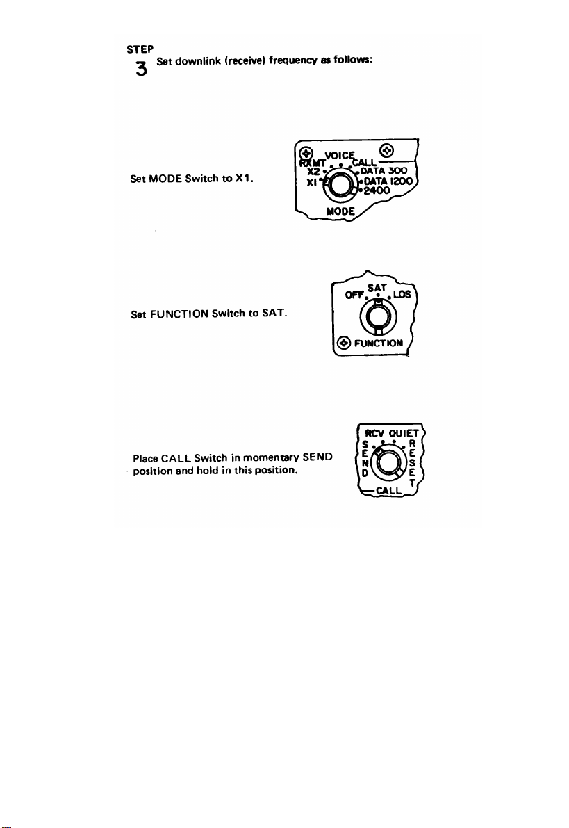
2-15. EXAMPLE OF PRESET PROCEDURE
Set FUNCTION Switch to SAT.
1)
2)
Set MODE Switch to X2.
3)
Set SAT OFFSET Switch to A, B, C, or D.
4)
Place CALL Switch in momentary SEND Position and
hold in this position.
NOTE
The FREQUENCY Display will indicate either:
● a frequency between 225.000 MHz and 398.995 MHz
(the last preset used), or
● 000.000 indicating that the current uplink (transmit)
frequency is invalid.
While holding the CALL Switch in SEND Position,
5)
use the MHZ and KHZ controls to adjust the fre-
quency displayed to 290.025 MHz. This will be
the uplink (transmit) frequency.
Release the CALL Switch and allow it to return to the
6)
RCV position. The RT-1402A/G will return to normal
operation.
7)
Set MODE Switch to X1.
2-36
8)
Place CALL Switch in momentary SEND Position and
hold in this position.
9)
While holding the CALL Switch in SEND, use the
MHZ and KHZ controls to adjust the frequency
displayed to 260.025 MHz. This will be the down-
Iink (receive) frequency.

10) Release the CALL Switch and allow it to return
to the RCV position. The RT-1402A/G will return
to normal operation.
NOTE
At this point, the uplink and downlink frequencies have both
been set and the offset associated with the SAT OFFSET
Switch position has been established as -30.000 MHz.
11) Set FUNCTION Switch to OFF.
12) Set FUNCTION Switch to SAT.
13) Verify that SAT OFFSET Switch is in the same
position as step 3.
NOTE
The frequency displayed will be 290.025 MHz (the uplink
frequency stored for the SAT OFFSET Switch position).
14) Set MODE Switch to X1.
15) Place the CALL Switch in the momentary SEND
Position and hold in this position.
NOTE
The frequency displayed will be 260.025 MHz (the down-
Iink frequency stored for the SAT OFFSET Switch position).
2-37

As the offset associated with the SAT OFFSET Switch position has been established as -30.000 MHz, changing the up-
Iink (transmit) frequency associated with the SAT OFFSET
Switch position will automatically change the downlink
(receive) frequency associated with SAT OFFSET Switch
position.
That is, were you to now set the uplink frequency for the SAT OFFSET Switch position to 300.025 MHz, the associated
downlink frequency would automatically be set to 270.025
MHz (in accordance with the established -30.000 MHz offset)
provided you do not activate the CALL Switch.
If you wish to operate in a mode requiring the transmit and
receive frequencies to be the same, the uplink and downlink
frequencies associated with the SAT OFFSET Position used
would have to be identical, thus establishing a 000.000 MHz
offset.
2-38

2-16. OPERATING PROCEDURES
WARNING
When operating equipment in enemy territory, bright lights
will make it easy for the enemy to detect your equipment. Use
blackout procedures to prevent detection by the enemy.
You as the operator must be aware of operation requirements
prior to referral to table 2-2. Selection of operation for desired
mode will be facilitated by table 2-2. Operating procedures for
all modes in both transmit or receive directly follow table 2-2.
NOTE
If your Backpack Radio Set should fail in any one of its operating modes, record the failure and notify organizational main-
tenance.
Due to limitations of the BA-5590/U Lithium Battery, continuous transmission must be limited to three minutes or less
when operating with two BA-5590/U batteries in the Battery
Box.
Table 2-2. OPERATING MODES MATRIX
OPERATING
MODE
CALL
DATA
X1
X2
RXMT
VOICE
TRANSMIT
PAGE NO.
2-40
2-45
2-50
2-53
2-56
2-58
RECEIVE
PAGE NO.
2-43
2-48
2-50
2-53
2-56
2-61
2-39

CALL MODE - TRANSMIT
Set up for SAT operation (page 2-19) or LOS operation (page 2-16).

CALL MODE - TRANSMIT
2-41

DATA MODE – TRANSMIT
2-42

CALL MODE – RECEIVE
Set up for SAT operation (page 2-19) or LOS operation (page 2-16).
2-43

CALL MODE – RECEIVE
2-44

DATA MODE – TRANSMIT
Set up for SAT opertion (page 2-19) or LOS operation (page 2-16).
2-45

DATA MODE – TRANSMIT
2-46
DATA MODE – TRANSMIT
2-47

DATA MODE - RECEIVE
STEP
Ensure compliance with operation requirements. Adjust
I
DISPLAY control ➂ cw to midrange.
STEP
Set
2
STEP
UP for SAT operation (page 2-19) or LOS operation
(page 2-16).
3
Refer to aplicable TM for data device control settings.
2-48

DATA MODE - RECEIVE
2-49

X1 MODE – TRANSMIT/RECEIVE
Ensure compliance with operation requirements. Adjust
DISPLAY control ➂ cw to midrange.
Electromagnetic radiation hazard exists within several feet of
the Medium Gain Antenna during transmit. Avoid prolonged
exposure in front of the dipole elements during transmit operation.
STEP
Set up
2
STEP
3
for SAT operation (page 2-19) or LOS operation
(page 2-16).
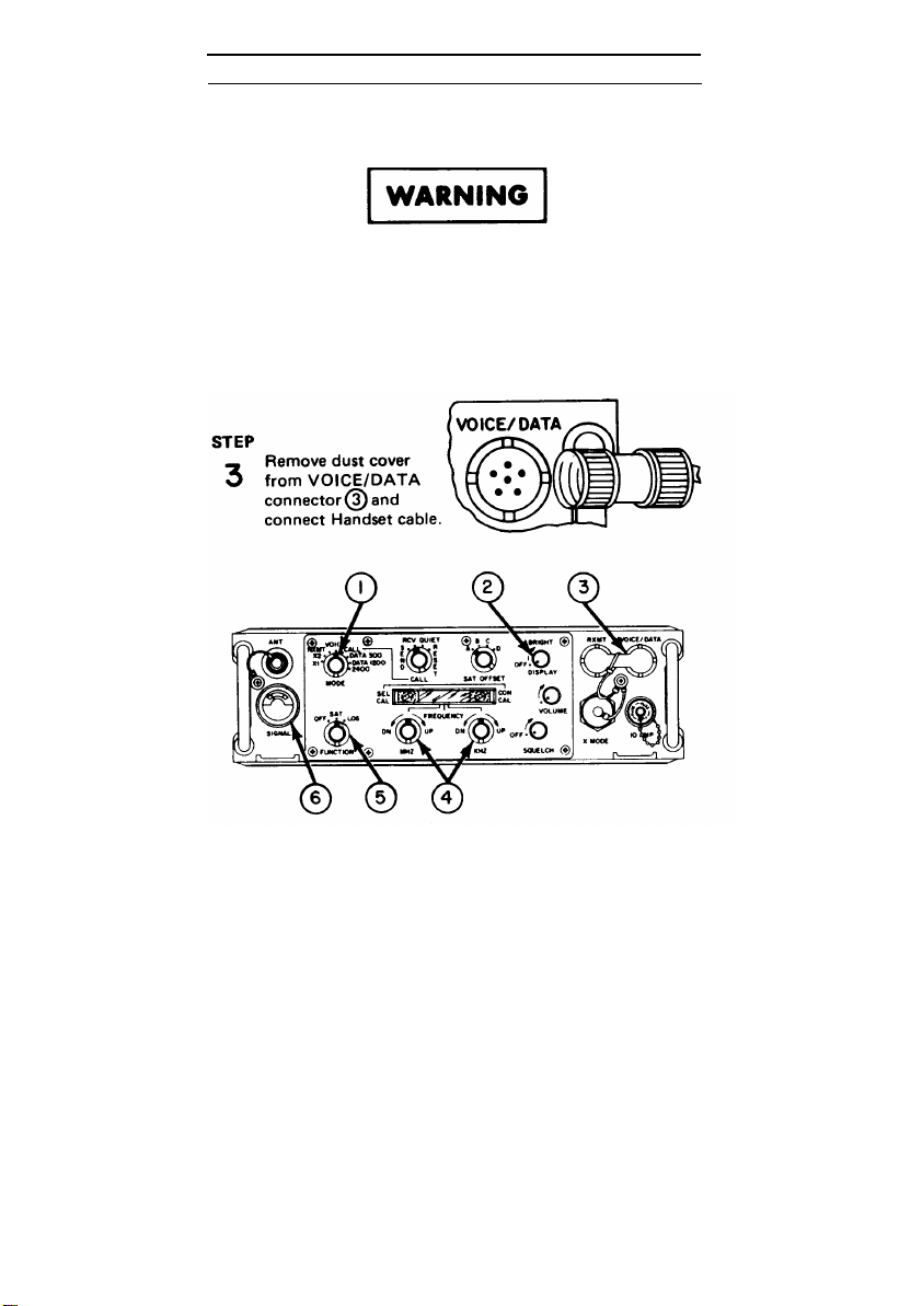
Remove dust cover from
VOICE/DATA connector
à and connect Cable
Assembly CX-13168/U.
Connect other end of cabl
to RADIO connector on
TSEC/KY-65.
2-50

X1 MODE - TRANSMIT/RECEIVE
Connect Handset cable to TSEC/KY-65 HANDSET
connector. Refer to TM 11-5810-280-12 for
TSEC/KY-65 operating instructions.
2-51

X1 MODE – TRANSMIT/RECEIVE
2-52

X2 MODE - TRANSMIT/RECEIVE
STEP
Ensure compliance with operation requirements. Adjust
I
DISPLAY control ➂ cw to midrange.
Electromagnetic radiation hazard exists within several feet of
the Medium Gain Antenna during transmit. Avoid prolonged
exposure in front of the dipole elements during transmit operation.
STEP
Set up for SAT operation (page 2-19) or LOS operation
2
(page 2-16).
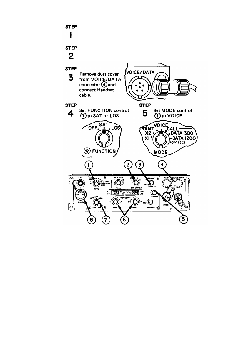
STEP
Remove dust cover from
3
X MODE connector@
and connect Cable Assembly CX-12991/U. Connect
other end of cable to RAD
connector on TSEC/KY-57.
Connect Handset cable to TSEC/KY-57 AUDIO connector. Refer to TM 11-5810-256-12 for TSEC/KY-57
operating instructions.
2-53

X2 MODE – TRANSMIT/RECEIVE
2-54

X2 MODE - TRANSMIT/RECEIVE
2-55

RXMT MODE – TRANSMIT/RECEIVE
STEP
Ensure compliance with operation requirements.
1
Electromagnetic radiation hazard exists within several feet of
the Medium Gain Antenna during transmit. Avoid prolonged
exposure in front of the dipole elements during transmit operation.
STEP
Set up for SAT operation (page 2-19) or LOS operation
2
(page 2-16).
STEP
Refer to RXMT setup (page 2-23) and perform STEP 2
3
thru 12.
2-56

RXMT MODE – TRANSMIT/RECEIVE
Adjust Radio Set AN/PRC-70, Radio Set AN/PRC-77 or
6
Radio Set AN/VRC-12 series for retransmit operation
according to procedures in applicable TM listed in
Appendix A.
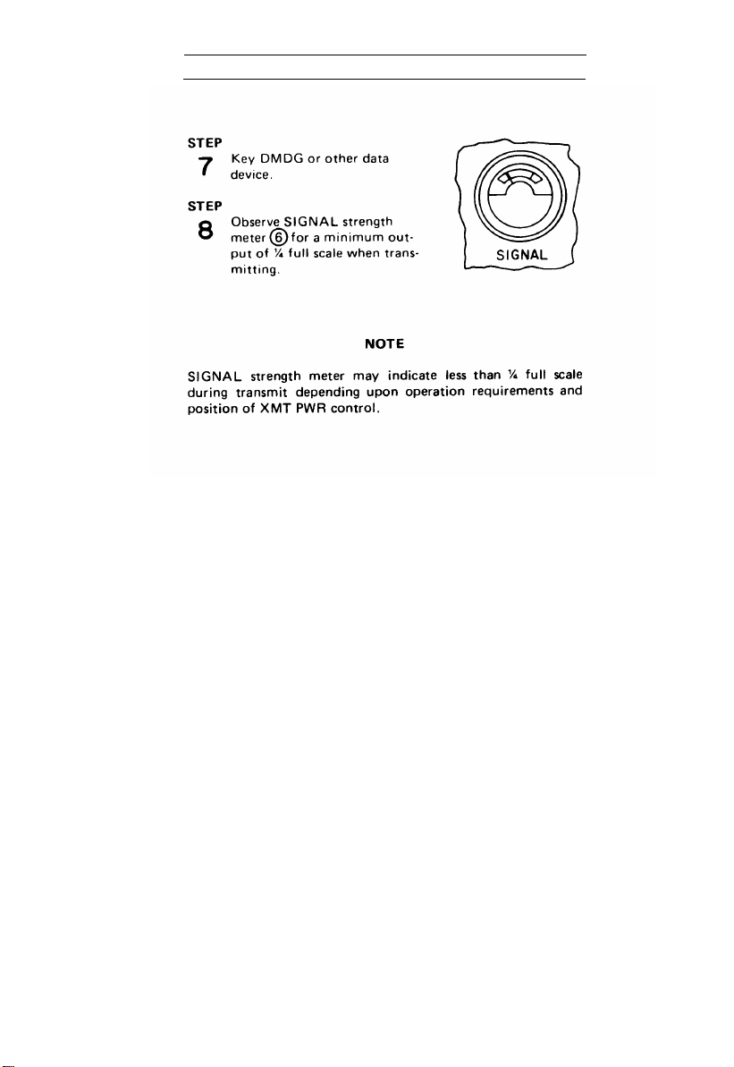
STEP
Observe SIGNAL strength meter ➂ for acceptable
7
indication during Transmit and Receive operation:
Transmit - ¼ full scale
minimum when
transmitting.
Receive - ¾ full scale
minimum when
receiving a good signal.
If ¾ full scale is not obtained for receive, reposition antenna
for peak meter deflection.
SIGNAL strength meter may indicate less than ¼ full scale
depending upon operation requirements and position of
XMT PWR control.
2-57
VOICE MODE – TRANSMIT
STEP
Ensure compliance with operation requirements. Adjust
1 DISPLAY control Á cw to midrange.
Electromagnetic radiation hazard exists within several feet of
the Medium Gain Antenna during transmit. Avoid prolonged
exposure in front of the dipole elements during transmit operation.
STEP
Set up for SAT operation (page 2-19) or LOS operation
2
(page 2-16).
2-58

VOICE MODE – TRANSMIT
2-59

VOICE MODE - TRANSMIT
2-60
VOICE MODE – RECEIVE
Ensure compliance with operation requirements. Adjust
DISPLAY control ➂ cw to midrange.
Set up for SAT operation (page 2-19) or LOS operation
(page 2-16).
2-61

VOICE MODE - RECEIVE
2-62

2-17. SHUTDOWN PROCEDURES
Complete shutdown of the Backpack Radio Set is accomplish-
ed by setting the FUNCTION control to OFF.
For shutdown of auxiliary data and security devices, refer to
applicable technical manuals in Appendix A.
2-63/(2-64 blank)


2-18. PREPARATION FOR MOVEMENT
Returning to mobile operation from at halt operation will take
you less than two minutes.
or conference calls from a satellite relay station will be
received. Refer to the following illustrations/procedures and
proceed with STEP 1.
In mobile operation, selective
2-65

2-66
STEP 8.

WARNING
Refer to page 2-17 and perform STEP 2 thru STEP 7.
12
2-67

2-19. INTERFACE EQUIPMENT CONFIGURATION
The Backpack Radio Set interfaces or operates in con-
a.
junction with other equipment in both SAT or LOS modes of
operation. The following illustrations will show you how to
configure the auxiliary equipment for interface with it. For a
basic description of this equipment, refer to page 1-14. For
detailed information and operating instructions, refer to the
appropriate technical manual listed in Appendix A.
b.
The following modes of operation require interfacing
with auxiliary equipment to complete the communications
scheme.
2-68
 Loading...