


ARMY
TM 11-5820-553-10
NAVY EE150-SN-OPl-010/E110-PRC 70
OPERATOR’S MANUAL
RADIO SET AN/PRC-70
(NSN 5820-01-062-8246)
This copy is a reprint which includes current
pages from Changes 1 and 2.
DEPARTMENTS OF THE ARMY AND THE NAVY
19 FEBRUARY 1982

TM 11-5820-553-10/EE150-SN-OPl-010/E110-PRC 70
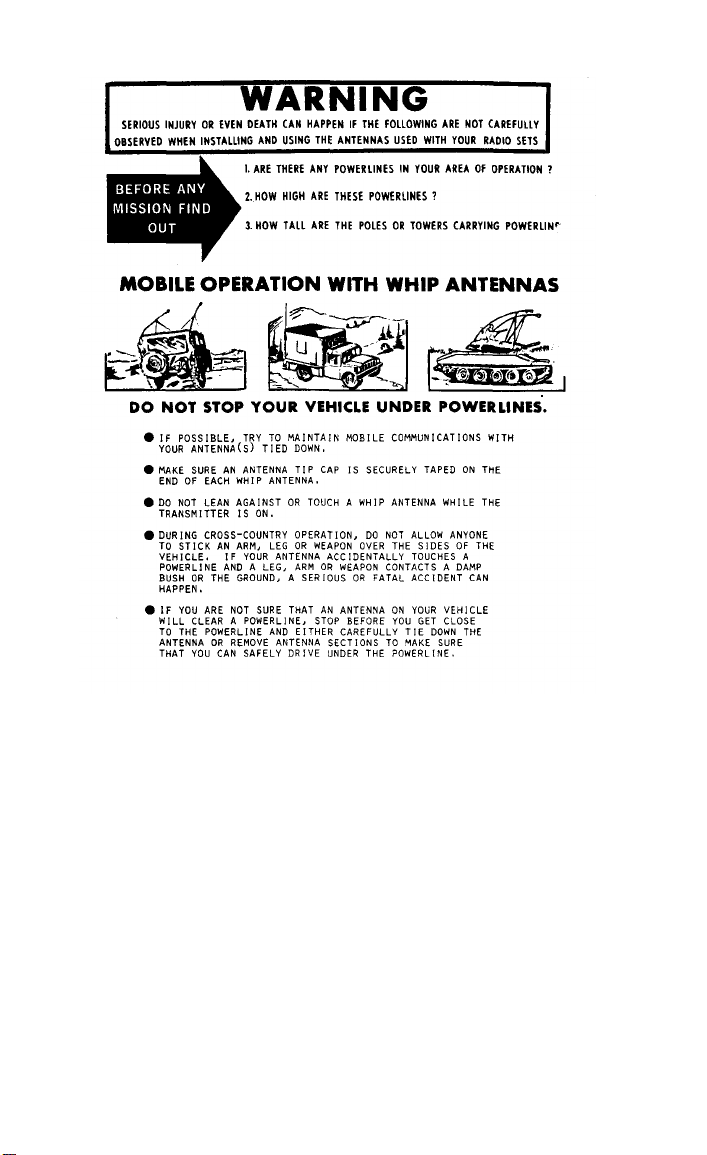
WARNING
Serious injury or death could result to personnel if the
whip antenna comes in contact with power lines.
When operating in HI PWR with the whip antenna, DO
NOT TOUCH the antenna when in transmit mode—an
RF burn can result.
This decal is located near the WIRE terminal and WHIP
antenna on the front panel of the radio set. It is applicable to BOTH long wire and whip antenna usage.
WARNING
Adequate ventilation should be provided while using
TRICHLOROTRIFLUOROETHANE. Prolonged
breathing of vapor should be avoided. The solvent
should not be used near heat or open flame; the products of decomposition are toxic and irritating. Since
TRICHLOROTRIFLUOROETHANE dissolves
natural oils, prolonged contact with skin should be
avoided. When necessary, use gloves which the solvent
cannot penetrate. If the solvent is taken internally, consult a physician immediately.

TM 11-5820-553-10/EE150-SN-OPl-010/E110-PRC 70
WARNING
A potential RF radiation hazard exists when Radio Set
AN/PRC-70 is operated in HI PWR, with the whip
antenna, either 6 or 9 foot (2 or 3 meters). This hazard is
increased when the radio is operated in the portable
(backpack) mode. For protection against these hazards,
observe the following safeguards:
a. Use a dummy load when operating the radio, if
possible, such as when performing Preventive Maintenance Checks and Services (PMCS) to determine
equipment readiness/availability.
b. Operate the radio in the off-the-back (fieldemplaced) mode, if possible, using either the doublet or
the long-wire antenna.
c. If a whip antenna must be used for transmissions
in the field-emplaced mode, use a microphone cable
long enough to maintain a distance of at least 1.7 feet
(50 centimeters) from the antenna.
d. If the radio must be operated in the portable (onthe-back) mode, use LO PWR or do not transmit for
longer than 30 seconds out of any 6-minute interval.
CAUTION
Do not attach antenna to this unit if high power
transmitters in the range 2-76 MHz are being operated
within 200 feet.
Change 1
A

TM 11-5820-553-10/EE150-SN-OPl-010/E110-PRC 70
CAUTION
FREQUENCY STABILITY CHECK
The AN/PRC-70 radio requires a radio frequency
stability check annually. Refer to your organizational
maintenance schedule to ensure your radio does not
become due for this check during a mission.
CAUTION
Handcrank Generator G-76/G must be producing
power BEFORE the AN/PRC-70 is turned on. Failure
to do this may damage the radio.
B
Change 1

TM 11-5820-553-10
TM 11-5820-553-10
D

TM 11-5820-553-10
SAFETY STEPS TO FOLLOW IF SOMEONE
IS THE VICTIM OF ELECTRICAL SHOCK
DO NOT TRY TO PULL OR GRAB THE INDIVIDUAL
IF POSSIBLE
, TURN OFF THE ELECTRICAL POWER
IF YOU CANNOT TURN OFF THE ELECTRICAL
POWER, PULL, PUSH, OR LIFT THE PERSON TO
SAFETY USING A WOODEN POLE OR A ROPE OR
SOME OTHER INSULATING MATERIAL
SEND FOR HELP AS SOON AS POSSIBLE
AFTER THE INJURED PERSON IS FREE OF
CONTACT WITH THE SOURCE OF ELECTRICAL
SHOCK, MOVE THE PERSON A SHORT DISTANCE
AWAY AND IMMEDIATELY START ARTIFICIAL
RESUSCITATION

TM 11-5820-553-10
F

TM 11-5820-553-10
EE150-SN-OPI-01B/E110-PRC 70
C2
CHANGE
DEPARTMENTS OF THE ARMY
AND THE NAVY
NO. 2
Washington, DC, 1 August 1987
OPERATOR’S MANUAL
RADIO SET AN/PRC-70
(NSN 5820-01-062-8246)
TM 1l-5820-533-10/EE150-SN-OPI-010/E110-PRC 70,
19 February 1982 is changed as follows:
1. Remove old pages and insert new pages as indicated
below. New or changed material is indicated by a vertical bar in the margin of the page. Added or revised
illustrations are indicated by a vertical bar adjacent to
the identification number.
Remove pages
i through iv . . . . . . . . . . . . . . . . . .
1-1 and 1-2 . . . . . . . . . . . . . . . . . . . .
1-5 through 1-10 . . . . . . . . . . . . . . .
2-3 AND 2-4 . . . . . . . . . . . . . . . . . . .
2-11 and 2-12 . . . . . . . . . . . . . . . . . .
2-15 through 2-26 . . . . . . . . . . . . . .
4-3 and 4-4 . . . . . . . . . . . . . . . . . . . .
4-7 through 4-10 . . . . . . . . . . . . . . .
4-17/(4-18 blank) . . . . . . . . . . . . . . .
A1 and A2 . . . . . . . . . . . . . . . . . .
Insert pages
i through iv
1-1 and 1-2
1-5 through 1-10
2-3 and 2-4
2-11 and 2-12
2-15 through 2-26
4-3 and 4-4
4-7 through 4-10
4-17/(4-18 blank)
A1 and A2
2. File this change sheet in front of the publication for
reference purposes.

Distribution authorized to the Department of Defense and DOD contractors only
for official use or for administration or operational purposes. This determination
was made on 26 March 1987. Other requests for this document will be referred
Commander, US Army Communications-Electronics Command and Fort
Monmouth, ATTN: AMSEL-ME-P, Fort Monmouth, NJ 07703-5000.
DESTRUCTION NOTICE–Destroy by any method that will
prevent disclosure of contents or reconstruction of the
document.


TM 11-5820-553-10
EE150-SN-OPl-010/E110-PRC 70
TECHNICAL MANUAL
NO. 11-5820-553-10
TECHNICAL MANUAL NO.
EE150-SN-OPI-010/E110-PRC 70
DEPARTMENTS OF THE
ARMY AND THE NAVY
Washington, DC, 19 Feb 82
OPERATOR’S MANUAL
RADIO SET AN/PRC-70
(NSN 5820-01-062-8246)
REPORTING ERRORS AND
RECOMMENDING IMPROVEMENTS
You can help improve this manual. If you find any
mistakes or if you know of a way to improve the procedures, please let us know. Mail your letter, DA Form 2028
(Recommended Changes to Publications and Blank
Forms), or DA Form 2028-2 located in back of this
manual direct to: Commander
Electronics Command and Fort Monmouth, ATTN:
AMSEL-ME-MP, Fort Monmouth, New Jersey 07702-5000.
, US Army Communications-
For Navy, mail comments to the Commander
Naval Warfare Systems Command,
Washington, DC 20363-5100.
In either case, a reply will be furnished direct to you.
Chapter
Section I. General
1. INTRODUCTION
Scope . . . . . . . . . . . . . . . . . . . 1-1
Consolidated Index of Army
Publications and Blank
Forms . . . . . . . . . . . . . . . . . . . .1-2
Maintenance Forms,
Records, and Reports . . . . . . . .1-3
Reporting Equipment Im-
provement Recommendations
(EIR) . . . . . . . . . . . . . . . . .... . . . . . . . . . . 1-4
Warranty Information . . . . . . . .1-5
II. Description and Data
Equipment Characteristics,
Capabilities, and Features . . . . .1-6
EE150-SN-OPI-01B/E110-PRC 70/Change 2
ATTN: SPAWAR8122,
, Space and
Paragraph
Page
1-1
1-1
1-1
1-2
1-2
1-2
i

TM 11-5820-553-10
Chapter 2
Section I.
Section II.
III.
IV.
Paragraph
Location and Description
of Major Components.
System Application. . . . .
Tabulated Data . . . . . . .
OPERATING
INSTRUCTIONS
Controls and Indicators
Damage From Improper
Settings . . . . . . . . . . . . .
Operator/Crew Controls
Operation Under Usual
Conditions
Types of Operation . . . . .
Preliminary Starting
Procedures . . . . . . . . . .
Portable Configuration.
Fixed Configuration. . . . .
Initial Adjustments. . . . .
Operating Procedures . . .
Operation Under Unusual
Conditions
Operation Under Emer-
gency Conditions . . . . .
Recognition and Identi-
fication of Jamming . . .
Antijamming Procedures . . . . . . . . 2-11
Preparation for Movement
Portable Configuration
Movement . . . . . . . . . . . . . . . . . . . . .2-12
Fixed Congifuration
Movement . . . . . . . . . . . . . . . . . . . . 2-13
Fixed Voice Configura-
tion Movement . . . . . . . . . . . .2-14
CW or FSK Configuration
Movement . . . . . . . . . . . . . . . . . . . . . 2-15
Retransmit Configuration
Movement . . . . . . . . . . . . . . . . . . . . . . 2-16
. . . . 1-7
1-8
. . . .
1-9
. . . .
2-1
2-2
2-3
2-4
. . .
. . . . 2-5
. . . . 2-6
. . . . 2-7
. . . 2-8
. . . 2-9
2-10
Page
1-3
1-7
1-7
2-1
2-1
2-5
2-5
2-5
2-7
2-15
2-15
2-21
2-23
2-24
2-26
2-26
2-27
2-27
2-28
Chapter 3.
Section I.
ii
MAINTENANCE
INSTRUCTIONS
Tools and Equipment
General. . . . . . . . . . . . . . . . . . . . . .3-1
II.
Lubrication Instructions
General . . . . . . . . . . . . . . . . . . .. . . . . . .3-2
3-1
3-1

TM 11-5820-553-10
III.
IV.
Chapter 4.
Section I.
II.
Preventive Maintenance
Checks and Services
(PMCS)
General . . . . . . . . . . . . . . . . . . . .3-3
Preventive Maintenance
Checks and Services. . . . . . . .3-4
Maintenance of the Radio
Set . . . . . . . . . . . . . . . . . . . . ..3-5
Troubleshooting
General . . . . . . . . . . . . . . . . . . .3-6
V.
Maintenance of Radio Set
General . . . . . . . . . . . . . . . . . . .3-7
MATERIEL USED IN
CONJUNCTION WITH
MAJOR ITEM
General
List of Auxiliary Equip-
merit . . . . . . . . . . . . . . . . . . . . 4-1
Installation Instruc-
tions for Auxiliary
Equipment
Voice Security Equip-
ment Configuration . . . . . . . .4-2
Code Burst and CW
Configuration . . . . . . . . . . . . .4-3
Digital Message Device Group
OA-8990 Configuration . . . . . . . . 4-4
Handcrank Generator
Configuration . . . . . . . . . . . . . . . . .4-5
Power Supply Configuration . . . . . 4-6
Paragraph
Page
3-1
3-2
3-2
3-3
3-3
4-1
4-1
4-4
4-8
4-10
4-14
Appendix A.
Section I.
II.
Section I.
REFERENCES . . . . . . . . . . . . .
B.
COMPONENTS OF END
ITEM LIST . . . . . . . . . . . . . .
Introduction . . . . . . . . . . . . . . . .
Integral Components of
End Item . . . . . . . . . . . . . . . . .
ADDITIONAL AUTHORI-
C.
ZATION LIST
Introduction . . . . . . . . . . . . . . . .
Additional Authorization
II.
List . . . . . . . . . . . . . . . . . . . . .
A-1
B-1
B-3
C-1
C-2
Change 2 iii

TM 11-5820-553-10
Section
Number
1-1
1-2
2-1
2-2
2-3
2-4
2-5
4-1
4-2
4-3
4-4
4-5
4-6
D. EXPENDABLE SUPPLIES
AND MATERIALS LIST
I. Introduction . . . . . . . . . . . . . . . .
II. Expendable Supplies and
Material List . . . . . . . . .
. . . . .
Paragraph
Page
D-1
D-2
LIST OF ILLUSTRATIONS
Title
Radio Set AN/PRC-70 . . . . . . . . . . .
Contents of Accessory Carrying Bag . .
RT-1133/PRC-70 Controls.
Radio Set AN/PRC-70 Portable Con-
figuration . . . . . . . . . . . . . . . . . . . 2-6
Doublet Antenna AS-2975/PRC-70 . . . . . . . . . . . . 2-8
Long Wire Antenna Configuration . . . . . . . 2-11
Retransmit Configuration . . . . . . . . . . . . . . . . 2-13
Voice Security Equipment Configuration 4-2
CW Configuration . . . . . . . . . . . . 4-5
Digital Message Device Group (DMDG),
OA-8990/P Configuration . . . . 4-8
Handcrank Generator, G-76/G Con-
figuration, . . . . . . . . . . . . . . . . 4-10
Battery Charging with
Generator G-76/G . . . . . . . . . . . . . . . . . . 4-12
Power Supply, PP-6148/U Configuration 4-16
Handcrank
Page
1-4
1-5
2-2
iv

TM 11-5820-553-10/EE150-SN-OPl-010/E110-PRC 70
CHAPTER 1
INTRODUCTION
Section I. GENERAL
1-1. Scope
This manual contains operator instructions for Radio
Set AN/PRC-70. Equipment description, installation
instructions, and maintenance duties for the operator
are included in the manual. Operating and maintenance
instructions for the auxiliary equipment used with the
AN/PRC-70 are contained in separate technical
manuals. Refer to appendix A for a listing of these
manuals.
1-2. Consolidated Index of Army Publications and
Blank Forms
Refer to the latest issue of DA Pam 310-1 to determine
whether there are new editions, changes or additional
publications pertaining to the equipment.
1-3. Maintenance Forms, Records, and Reports
a. Reports of Maintenance and Unsatisfactory
Equipment. Department of the Army forms and pro-
cedures used for equipment maintenance will be those
prescribed by DA Pam 738-750, as contained in
Maintenance Management Update. Navy personnel will
report maintenance performed utilizing the
Maintenance Data Collection Subsystem (MDCS) IAW
OPNAVINST 4790.2, Vol 3 and unsatisfactory
material/conditions (UR submissions) IAW OP-
NAVINST 4790.2, Vol 2, chapter 17.
b. Report of Packaging and Handling Deficiencies.
Fill out and forward SF 364 (Report of Discrepancy
ROD)) as prescribed in AR 735-11-2/DLAR 4140.55/
NAVMATINST 4355.73B/AFR 400-54/MCO 4430.3H.
Change 2
1-1

TM 11-5820-553-10/EE150-SN-OPl-010/E110-PRC 70
c.
Discrepancy in Shipment Report (DISREP) (SF
361). Fill out and forward Discrepancy in Shipment
Report (DISREP) (SF 361) as prescribed in AR 55-38/
NAVSUPINST 4610.33C/AFR 75-18/MCO P4610
.19D/DLAR 4500.15.
1-4. Reporting Equipment Improvement
Recommendations (EIR)
a. Army. If your Radio Set AN/PRC-70 needs
improvement, let us know. Send us an EIR. You, the
user, are the only one who can tell us what you don’t
like about the design. Put it on an SF 368 (Quality
Deficiency Report). Mail it to Commander, US Army
Communications—Electronics Command and Fort
Monmouth, ATTN: AMSEL—PA—MA—D, Fort
Monmouth, New Jersey 07703—5000. We’ll send you
a reply.
b. Navy. Navy personnel are encouraged to submit
EIR's through their local Beneficial Suggestion Pro-
gram.
1-5. Warranty Information
Radio Set AN/PRC-70 is warranted by the contractor
for a period of 12 months. It starts on the date of
Government acceptance indicated on the appropriate
DD Form 2408-9. Report all defects in material or
workmanship to your supervisor who will take appropriate action through your Organization's maintenance shop.
Section II.
1-6. Equipment Characteristics, Capabilities and
Features (fig. 1-1)
Radio Set AN/PRC-70, referred to hereafter as the
radio set, is a medium-to-long-range communications
set which operates in the 2 to 76 MHz frequency band.
Various configurations of this equipment are possible so
that it may be transported by one or two persons or installed at fixed sites such as field headquarters, command
posts, etc. The radio set may be operated in all kinds of
1-2
Change 2
DESCRIPTION AND DATA

TM 11-5820-553-10
weather and terrain. Operating modes include
amplitude modulation (AM), single sideband (SSB),
continuous wave (CW), frequency modulation (FM),
and frequency-shift keying (FSK). Provisions are
included for the connection of separate security
devices to allow secure communications in selected
modes. Two radio sets may be connected together
for retransmission purposes.
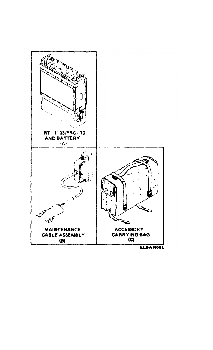
1-7. Location and Description of Major
Components
The radio set consists of the items shown in figures
1-1 and 1-2. The items not described in separate
technical manuals are described in the following
subparagraphs.
1-3
TM 11-5820-553-10
1-4
Figure 1-1. Radio Set AN/PRC- 70.

Change 2
1-5
Figure 1-2.
TM 11-5820-553-10
Figure 1-2.

TM 11-5820-553-10
a. Receiver-Transmitter RT-1133/PRC-70. The
Receiver-Transmitter RT-1133/PRC-70 (A, fig.
1-1) is the major assembly of the radio set. Receiver-
Transmitter RT-1133/PRC-70 is referred to
hereafter as the RT unit. The RT unit is housed in a
metal case and contains the receive and transmit
circuits. Controls for the operator and cable connectors are located on the front panel of the RT unit.
b. Accessory Carrying Bag. The accessory
carrying bag (C, fig.1-1) is used for carrying the
following items (fig. 1-2):
(1) Handset H-250/U.
(2) Headset H-251/U.
(3) CW
CX-13101/PRC-70.
(4) Doublet Antenna AS-2975 PRC-70 con-
sisting of:
(a) 5-foot measuring tape.
(b) Ground rod.
(c) Balun assembly with RG-58 Cable
Assembly.
(d) 25-foot RG-25 Cable Assembly with BNC
adapter.
(e) Halyard assembly (2 each).
(f) Wire rope assembly (2 each).
(5) Whip Antenna AS-2974/PRC-70 consisting
of:
(a) 6-foot whip (4 sections).
(b) 9-foot whip (6 sections).
(c) Swivel antenna base.
c. Maintenance Cable Assembly. This assembly
(B, fig. 1-1) connects the RT unit to a power supply
for operating, testing, and troubleshooting the RT
unit without a battery.
d. Doublet Antenna AS-2975/PRC-70. This
assembly is a half-wave portable antenna that is
adjustable for an operating frequency between 2 and
30 MHz and is only used in fixed configurations.
Key KY-116/U
with Cable
1-6

TM 11-5820-553-10/EE150-SN-OPl-010/E110-PRC 70
e. Whip
assembly consists of a foldable 6-foot antenna, a
foldable 9-foot antenna, and a swivel antenna base.
The 6-foot antenna is used for the 4 to 76 MHz
range and the 9-foot antenna is used for the 3 to 76
MHz range. The whip antenna assembly is required
for portable configurations.
1-8. System Application
The radio set is a lightweight transceiver designed
for manpack use. It operates in the frequency range
of 2 to 76 MHz in AM, CW, SSB, and FSK modes
and from 30 to 76 MHz in FM mode. The radio set
has a long-range communications capability up to
2500 miles (4000 km). The 30 to 76 MHz SSB mode
offers flexibility for setting up communication nets
and links. The built-in antenna coupler is automatic,
and provides the best match with whip, long wire,
and doublet antenna assemblies.
1-9. Tabulated Data
The following subparagraphs describe the technical
data for the radio set. Table 1-1 lists the physical
data of the items of the radio set. The relationship
between the various modes, frequencies, antenna
assemblies and distances are shown in tables 1-2
and 1-3.
a. Receiver-Transmitter RT-1133/PRC-70
Input Voltage . . . . . . . . . . . . . . .+20 to +32 vdc
Power Consumption:
Receive Mode .. . . . . . . . . . . . 7 watts maximum
Low-Power Transmit Mode. . . .50 watts maximum
High-Power Transmit Mode
FSK, CW, FM, AM . . . . . . . . . . 160 watts maximum
SSB . . . . . . . . . . . . . 115 watts maximum
Power Output:
Duty Cycle . . . . . . . . . . . . . .9 to 1 receive-to-transmit
Antenna AS-2974/PRC-70. This
ratio.
Change 2
1-7

TM 11-5820-553-10
High-Power Mode
CW, FM*, FSK. . . . . . . . . . . 21-42 watts average
SSB . . . . . . . . . . . . . . . . . . . . . . .
AM . . . . . . . . . . . . . . . . . . . . . . . 7.5 watts carrier, 7.5
Low-Power Mode . . . . . . . . . .3 watts, +2dB, -2.5 dB
Frequency Range. . . . . . . . . . .2.000 to 75.9999 MHz in
* FM transmit enabled only in 30.0000 to 75.9999 MHz range.
NOTE
A temperature-sensing switch is located
in the power amplifier module. If continuous transmission at HI PWR is
required during high temperatures the
RT unit may switch to lower power
(approximately
proximately
operation. When the temperature is
sufficiently reduced the RT unit will
automatically return to the higher power
level.
Receiver Sensitivity:
FM . . . . . . . . . . . . . . . . . . . 0.60µV
SSB, FSK, CW . . . . . . . . . . . . . 0.375 to
AM . . . . . . . . . . . . . . . . . . . . . .2.50
Receiver Signal-to-Noise
Ratio . . . . . . . . . . . . . . . . . . . .10 dB at referenced
Receiver Selectivity:
FM . . . . . . . . . . . . . . . . . . . . . . . . . .32 kHz at 6dB
SSB, CW, FSK . . . . . . . . . . . . .2.8 kHz at 6 dB
AM. . . . . . . . . . . . . . . . . . . . 6.0 kHz at 6 dB
3 watts) after ap-
10 minutes of such
21-42 watts peak en-
velope power
watts upper sideband.
30 watts PEP at
85%
minimum
100 Hz steps
(varies with frequency)
modulation
0.50
µV
sensitivity
70 kHz at 60 dB
4.0 kHz at 26 dB
6.0 kHz at 60 dB
14.0 kHz at 60 dB
µV
1-8

TM 11-5820-553-10
Doublet Antenna AS-2975/PRC-70
b.
Frequency Range . . . . . . . . . . . . 2 to 30 MHz
(normal range)
Input Impedance. . . . . . . . . . . . 50 ohms
Whip Antenna AS-2974/PRC-70
c.
6- foot section . . . . . . . . . . . . . . 4 to 76 MHz
9-foot section . . . . . . . . . . . . . . .3 to 76 MHz
Table 1-1. Items Comprising an Operable Equipment
Dimensions
Length Depth Width Weight
NSN
Item
5820-01-062-8246 Radio Set
AN/PRC-70
Consisting
of:
5820-01-073-9114 Receiver-
Transmitter
RT-1133/
PRC-70
5995-01-092-5943 Maintenance
Cable
Assembly 1 60 –
Accessory
Carrying
Bag
5985-01-073-5602 Doublet
Antenna
AS-2975/
PRC-70
5985-01-073-5601 Whip An-
tenna
AS-2974/
PRC-70
(6 ft)
(9 ft)
5965-01-017-0549 Headset
H-251/U 1 8 4
5965-00-043-3463 Handset
H-250/U 1 8 2
5805-00-503-3395 CW Key KY-
116/U
with
(in.) (in.) (in.) (lb.)
Qty
4 11.9 13.25 21.0
1
1 11 17.5
1 2808 –
1
72 –
1 108 –
153
–
6.5
—
– 0.75
—
1.00
4
2
3
0.45
2.0
5.25
0.7
0.5
0.4
Change 2
1-9

TM 11-5820-553-10
Table 1-1. Items Comprising an Operable
NSN
5995-01-073-6123
Equipment- Continued
Length Depth Width Weight
(in.) (in.)
Item
Qty
Cable CX-
Dimensions
13101/
PRC-70
Ground Rod
SMC
746768/800-
45 NOTE 1 18 –
The following equipment is required but not supplied as part of the AN/PRC-70.
6140-01-089-7636 Battery
BB-542/U 1 12.2 2.56 4.0
Table 1-2. Operating Modes, Antennas, and Frequencies
Operating Mode
FM
Antenna Frequency
6-foot whip
30 to 76 MHz
9-foot whip 30 to 76 MHz
CW, FSK, AM, SSB
6-foot whip
9-foot whip
Doublet
4 to 76 MHz
3 to 76 MHz
2 to 30 MHz
(normal)
Table 1-3. Operating Modes, Antennas, and Distances
(in.) (lb.)
0.75
0.8
7.0
Mode
CW
Antenna
AS-2975/PRC-70
Distance Range
up to 2,500
miles*
SSB Voice, AM AS-2975/PRC-70 0–500 miles
SSB Voice, FM
AM
FM
AS-2974/PRC-70
AS-2974/PRC-70 0–15 miles
AS-2974/PRC-70
0–25 miles
0–15 miles
*Long wire antenna may be used (para 2-6b).
1-10

TM 11-5820-553-10
CHAPTER 2
OPERATING INSTRUCTIONS
Section I. CONTROLS
AND INDICATORS
2-1. Damage From Improper Settings
No damage will result to the equipment from improper control settings at turn-on. Battery life will
be shortened by some control settings. Maximum
battery drain occurs when the POWER switch is set
to HI PWR and the SQUELCH switch is held in the
DIAL LIGHT position. For best battery life use
other settings of the controls when possible.
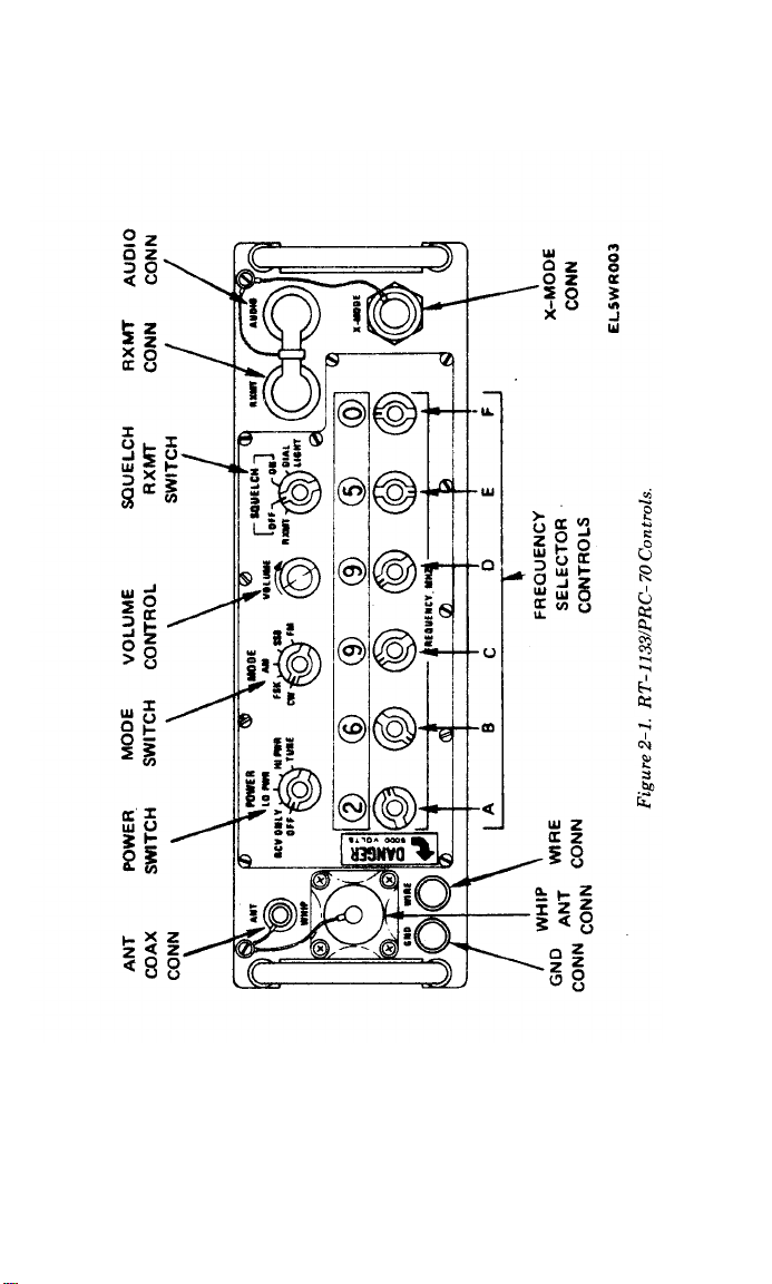
2-2. Operator/Crew Controls
Figure 2-1 shows the RT unit front panel controls.
Table 2-1 lists the operator controls, indicators, and
connectors and describes their functions.
CAUTION
Do not change front panel controls while
RT unit is transmitting.
2-1
TM 11-5820-553-10
Figure 2-1.
2-2
Figure 2-1.

TM 11-5820-553-10
Table 2-1. Controls, Indicators and Connectors
Control, indicator,
or connector
Function
POWER switch Sets major functions of RT-l133/PRC-
70 as follows:
Positions:
OFF
RCV ONLY
LO PWR
Removes all power from RT unit.
Applies power to receive circuits only,
Allows transmission in low-power mode
when transmitter is keyed. Output is
approximately 3 watts,
HI PWR
Allows transmission in high-power mode
when transmitter is keyed. Output is
approximately 30 watts.
TUNE Starts automatic tuning sequence in unit
to tune antenna coupler. Switch is
spring loaded in this position and
returns to HI PWR position when
released.
MODE switch
Selects operating mode of unit. Modes
are CW, FSK, AM, SSB, and FM*.
* Transmit enables only in 30.0000 to 75.9999 MHz range.
VOLUME control
SQUELCH switch
Sets volume of received audio.
Controls operation of receiver squelch
and unit dial lights as follows:
Positions:
RXMT
Actuates switching circuit which con-
trols second RT-1133/PRC-70 in
retransmit mode.
OFF
ON
Disables squelch circuit.
Enables receiver squelch in voice modes.
Squelch is disabled if MODE switch is
set to CW or FSK.
DIAL LIGHT
Momentary switch position; applies
power to dial lights. Switch returns to
ON position when released.
RXMT connector
Connects
unit to second RT unit
RT-1133/PRC-70 in retransmit mode.
Connects CW Key KY-116/U for CW or
FSK operation.
AUDIO connector
Connects Handset H-250/U to RT unit
for normal voice operation and Headset
H-251/U during CW or FSK operation.
X-MODE
connector
Connects voice security applique to unit
for secure voice operation.
2-3

TM 11-5820-553-10
Table 2-1. Controls, Indicators and Connectors–Continued
Control. indicator
or connector
CAUTION
Dummy shorting caps for AN/PRC-70 and
AN/PRC-77 are not interchangeable.
NOTE
Shorting cap must be connected to connector at all
times when voice security applique is not being
used or power to RT unit will be interrupted.
ANT connector
Installing the coax connector of the doublet antenna to the antenna connector removes all R.F.
power from the wire connector post.
WHIP connector
Installing the antenna swivel base to the whip connector removes all R.F. power from the antenna and
wire connectors.
WIRE connector
GND connector
FREQUENCY
selector controls
and indicators:
A
B
C
D
E
F
Connects feedline for Doublet Antenna
AS-2975/PRC-70 to RT unit.
NOTE
Connects whip Antenna AS-2974/PRC-70 to
RT unit.
NOTE
Connects random wire length antennas to
RT unit.
Connects ground wire to RT unit.
Operating frequency is changed by rotat-
ing frequency selector controls while
observing frequency readout numerals.
FM transmit is disabled by these
controls below 30.0000 MHz setting.
Megahertz tens selector
Megahertz unit selector
Kilohertz hundreds selector
Kilohertz tens selector
Kilohertz units selector
Hertz hundreds selector
Function
2-4
Change 2

TM 11-5820-553-10
Section II. OPERATION UNDER
USUAL CONDITIONS
2-3. Types of Operation
Two types of operation are possible using the radio
set: portable and fixed configurations. Refer to
Chapter 4, Section II, for the installation and
operation
of configurations
using
auxiliary
equipment.
2-4. Preliminary Starting Procedures
Before operating the radio set, set controls as
follows:
Control
POWER switch
MODE switch
VOLUME control
SQUELCH switch
FREQUENCY selector
controls
OFF
Operating mode desired
Midrange
OFF
Operating frequency desired
Setting
2-5. Portable Configuration
Figure 2-2 shows the portable configuration. For
operation in this configuration, assemble equipment
as follows:
CAUTION
The antenna base must be screwed down
all the way until the antenna base meets
with the connector. If a gap is left between the antenna base and the connector,
the antenna base screw may break.
2-5

TM 11-5820-553-10
Figure 2-2. Radio Set AN/PRC- 70 Portable Configuration.
a. Install the antenna swivel base in RT unit
WHIP connector.
2-6

TM 11-5820-553-10
b.
Assemble the whip antenna by unfolding either
the 6-foot or the 9-foot section, and pressing
ferrules together.
c. Screw whip antenna into the antenna swivel
base.
d. For voice operation, connect Handset H-250/U
to the AUDIO connector on the RT unit.
e. For CW operation, connect Headset H-251/U
to the AUDIO connector and CW Key KY-116/U
with cable CX- 13101/PRC-70 to the RXMT connector on the RT unit.
2-6. Fixed Configuration
This paragraph contains setup and assembly for
operable equipment in fixed configurations. Nonportable equipment use is determined by the local
commander.
NOTE
When using the doublet antenna, the
direction of the antenna wire should be at
right angles to the desired direction of
transmission.
a.
Installation of Doublet Antenna. Figure 2-3
shows the equipment setup for this configuration.
The halyard assemblies may be attached to any
suitable structure, manmade or natural, that will
provide maximum height, correct antenna length,
and antenna orientation at a right angle to the
direction of desired transmission.
2-7

TM 11-5820-553-10
Figure 2-3.
2-8
Figure 2-3.

TM 11-5820-553-10
(1) Select a good location for the installation of
the doublet antenna.
(2) Calculate antenna length of each leg by the
following formula:
234
Operating Frequency in MHz
NOTE
Total antenna length is the length of both
antenna pieces added together.
EXAMPLE
Operating Frequency is 2 MHz,
117 (ft) each antenna leg.
Total antenna length for 2 MHz = 2 x 117
ft or 234 ft.
NOTE
Due to corrosive effects of weather on the
antenna wire the radio may not tune to
this length. To compensate for this effect,
the length of each leg of the
AS-2975/PRC-70 including bobbins,
should be shortened by one foot below the
length calculated from the standard
formula 234 ft. (MHz).
(3) Remove Doublet Antenna Assembly
AS-2975/PRC-70 from accessory carrying bag (fig.
1-2).
(4) Connect the two wire rope assemblies to the
balun assembly as shown in figure 2-3.
(5) Unwind the desired antenna wire length as
determined by (2) above on both wire rope assemblies.
(6) Unwind the nylon rope from the two halyard
assemblies.
(7) Connect the end of the rope of the halyard
assemblies to the reel of the two-wire rope assemblies.
(8) Secure the halyard assemblies to the
= (ft) of one leg
234
=
2 MHz
2-9

TM 11-5820-553-10
selected structures.
(9) Place the RT unit under the balun assembly
near the RG-58 Cable Assembly.
(10) Place ground rod in the ground near the RT
unit. Connect the ground wire to the GND terminal
on the RT unit.
(11) Connect the RG-58 Cable Assembly to the
ANT connector on the RT unit. If necessary, use the
extra 25-foot RG-58 Cable Assembly with Adapter
UG-914/U.
b. Operation With Long Wire Antenna. The radio
set may be operated by using the two wire rope
assemblies and the two halyard assemblies of the
doublet antenna. The two guy hooks of the wire rope
assembly are overlayed and bolted together. This
will provide an antenna wire length of 234 feet. The
arrangement of equipment is shown in figure 2-4.
This long wire antenna arrangement can be used at
any operating frequency from 6 to 30 MHz.
2-10

Figure 2-4.
TM 11-5820-553-10
Figure 2-4.
2-11

TM 11-5820-553-10
c. Retransmit Configuration.
(1) Equipment setup. Two radio sets can be
operated together to establish retransmission of
voice signals on AM, FM, and SSB. Figure 2-5 shows
this configuration which includes the following items:
(a) Two Receiver-Transmitters RT-1133/
PRC-70.
(b) Two Batteries BB-542/U.
(c) Transmission Cable Kit MK-456 or
MK-456A/GRC.
(d) One Doublet Antenna AS-2975/PRC-70.
(e) One 6-foot or 9-foot Whip Antenna
AS-2974/PRC-70.
(f) Handset H-250/U.
2-12
Change 2

TM 11-5820-553-10
Figure 2-5. Retransmit Configuration.
2-13

TM 11-5820-553-10
(2) Assembly. Assemble the doublet antenna as
described in paragraph 2-6. Perform the following
steps:
(3) Operating Instructions.
(a) Set controls on RT unit as follows:
Control
POWER switch
MODE switch
VOLUME control
SQUELCH switch
FREQUENCY SELECTOR
switch
OFF
Operating mode desired
Midrange
OFF
To assigned operating
frequencies
Setting
(b) Initial tune up.
1. Turn RT unit
B POWER switch
to HI
PWR.
2. Set VOLUME control to a level
which
permits monitoring of any radio traffic on the
specified frequencies.
If undesired traffic exists,
turn squelch switch to RMXT and observe if the
unit stays squelched. If the squelch breaks, even
marginally, do not use that frequency. A good link
check can be made at this point using the received
desired frequency to assure that it will break the
squelch.
3. Perform the coupler tune sequence by
momentarily setting the POWER switch to TUNE.
This switch is spring loaded and will return to the
HI PWR position.
4. Set the POWER switch to HI PWR or
LO PWR as desired.
5. Tune unit C in a similar manner and set
both units’ SQUELCH switch to RXMT position.
6. Connect RXMT Cable CX-4656/GRC.
7. Set RT units A and B to FM mode on the
specified VHF frequency.
8. Set RT units C and D to the SSB mode
on the specified VHF frequency.
9. Communication link can be established
by voice transmission from unit A to reception at
2-14

TM 11-5820-553-10
unit D. Proper relay operation can be determined by
monitoring communications at CX-4656/GRC
audio connector. To prevent a loss of message, the
operator at the transmitting end should wait until
his unit squelches (noise is muted) before responding
to the received message. This will take approximately 2 seconds.
10. To shut down the equipment, set both
RT unit POWER switches to OFF.
2-7. Initial Adjustments
No adjustments of the radio set are necessary.
2-8. Operating Procedures
a. Equipment Starting. Start the equipment in
accordance with the following procedures:
WARNING
Serious injury or death could result to
personnel if the whip antenna comes in
contact with power lines.
(1) Set RT unit to desired frequency.
(2) Set RT unit POWER switch to RCV ONLY.
(3) Adjust RT unit VOLUME control for
suitable audio output level.
NOTE
The POWER switch is spring loaded in
the TUNE position and will return to HI
PWR when released. When RT unit is in
the coupler tuning mode, radio silence is
broken.
When the POWER switch is placed in the
TUNE (momentary spring loaded)
coupler unit will
position,
automatically tune to match the power
amplifier to the antenna being used. If a
good match is made, the tune cycle will
stop and the RT will be ready for use. If a
the
2-15

TM 11-5820-553-10
good match cannot be made within 15
seconds, the coupler will stop the tune
cycle. A no-tune condition will exist and
is indicated by a series of 2000 Hz beeps
when the RT is keyed. In SSB mode, the
operator must talk into the handset to
detect a no-tune condition.
(4) Momentarily set RT unit POWER switch to
TUNE and release. Allow 15 seconds for tuning to
be completed (when TUNE tone disappears from
handset). Once coupler tuning is completed, the
MODE switch can be changed without having to
retune.
(5) A beeper (no-tune) tone will result if the
antenna coupler does not provide a proper match.
Some power may be available and communication
should be attempted even though the antenna is not
optimum matched. Several corrective actions may
be taken to improve the match and are listed below:
(a) Move POWER switch to RCV ONLY and try
tuning again.
(b) Change frequency and try tuning again.
(c) Check antenna for damage.
(d) Check doublet antenna for proper length.
(e) Move to different location if near some large
object (tree, rock building, etc.).
(f) Check battery. Hold dial lamp switch on and
key transmitter. Dial lamps should not go out.
WARNING
When operating in HI PWR with the
whip antenna, do not touch the antenna
when in transmit mode—an RF burn can
result.
A potential RF radiation hazard exists
when Radio Set AN/PRC-70 is operated
with the whip antenna, either 2 or 3
meters. This hazard is increased when the
radio is operated in the portable (backpack) mode. For protection against these
2-16
Change 2

TM 11-5820-553-10/EE150-SN-OPl-010/E110-PRC 70
hazards,
observe
the
following
safeguards:
a. Use a dummy load when operating
the radio, if possible, such as when
performing
Preventive Maintenance
Cheeks and Services (PMCS) to determine
equipment readiness/availability.
b. Operate the radio in the off-the-back
(field-emplaced) mode, if possible, using
either the doublet or the long-wire antenna.
c. If a whip antenna must be used for
transmissions in the field-emplaced mode,
use a microphone cable long enough to
maintain a distance of at least 50 centimeters
from the antenna.
d. If the radio must be operated in the
portable (on-the-back) mode, do not transmit for longer than 30 seconds out of any
6-minute interval.
(6) Set RT unit POWER switch to LO PWR.
(7) Set RT unit SQUELCH switch to ON (if
desired).
NOTE
If RT unit FREQUENCY selectors are
reset, momentarily set POWER switch to
TUNE and release. After retuning is
completed (within 15 seeonds), LO PWR
position of POWER switch may be
selected.
b. Voice Mode Operation. Transmit in any of the
voice modes by pressing the H-250/U Handset
push-to-talk button and speaking into the
microphone.
c. Standard CW Operation. Use Headset
H-251/U for CW operation. To transmit in the
standard CW mode, key the RT unit with CW Key
KY-116/U.
Change 2
2-17

TM 11-5820-553-10
WARNING
Serious injury or death could
personnel if the whip antenna
result to
comes in
contact with power lines.
d. Miscellaneous Operating Notes.
(1) Changing settings of RT
unit controls
should not be done while transmitter is keyed.
(2) To read FREQUENCY selector dials in poor
light, set SQUELCH switch to DIAL LIGHT. The
switch is spring-loaded in this position and will
return to ON when released.
(3) The radio set will not operate well with FM
sets having 25-kHz channelization unless the RT
unit has been modified for this mode. Such
modification can be performed by depot support
maintenance personnel.
e. Equipment Shutdown. To shut down the
equipment set the RT unit POWER switch to OFF.
f. Special Tuning Procedures. Certain frequencies
and loading conditions may affect tuning. If several
attempts at tuning fail, the operator should try the
following steps:
(1) Change the location of the antenna. Objects
near the antenna (including the operator, other
people, and the handset cable) affect the impedance
of the antenna. The operator can try to tune the
radio set after doing one or more of the following:
(a) Change his position relative to the an-
tenna.
(b) Move the handset cable away from the
antenna.
(c) Move the radio position if it is sitting close
to a tree, post, or some other conductor.
(2) Change frequency.
(a) Change the frequency of the radio set in
100 kHz steps to a frequency at which it will tune.
(b) Change frequency as in (2)(a) then, change
2-18

TM 11-5820-553-10
back to the desired frequency. This will often solve
the problem.
g. Field Checkout. There may be times when the
operator wants to know the operational condition of
the unit without breaking radio silence. The
following steps will provide a partial check and may
lead to the corrective action required:
(1) With POWER switch OFF, attach battery.
(2) Set FREQUENCY to 10.997 MHz, MODE
switch to SSB, and SQUELCH switch to OFF. Do
not connect any antenna to the radio.
(3) Turn POWER switch to RCV ONLY and
adjust VOLUME control to obtain a suitable level
of tone which should have a frequency of approximately 3000 Hz.
(4) Change the FREQUENCY to 10.998 MHz
and observe that tone changes to a frequency of
approximately 2000 Hz. This test indicates that
power supplies,
audio, and IF circuits, volume
control, and handset or headset are operable. If no
audio is heard, turn VOLUME control fully
clockwise. If audio is still not heard, try a new
handset and/or new battery.
(5) To check squelch operation, set
FREQUENCY to 10.898 MHz and turn SQUELCH
switch to ON. The radio should mute (no audio or
noise unless strong traffic exists on that frequency).
Set FREQUENCY to 10.998 MHz and observe that
squelch breaks and 2000 Hz tone is heard.
(6) A battery check can be accomplished by
setting controls as given below:
(a) FREQUENCY at 10.998 MHz.
(b) Turn SQUELCH switch to DIAL LIGHT
and observe light level. While holding switch in
DIAL LIGHT position, change FREQUENCY to
14.998 MHz. The bandswitch motor will run and
lights should not dim (motor drains about 200 mA
from battery).
2-19

TM 11-5820-553-10
(7) Transmitter (hot tune) check can be accomp-
lished into an antenna as given below.
NOTE
Radio silence will be broken.
(a) Set FREQUENCY to assigned frequency.
(b) Turn POWER switch to TUNE and note
presence of a tone in handset while coupler is tuning
(Radio silence is broken.)
(c) Note that tune sequence finishes in less
than 15 seconds and that tone shuts off.
(d) Key transmitter and observe that voice
sidetone is heard.
(e)
If a series of beeps (a 2000 Hz tone coming
on at an interval of approximately 1 second) is heard,
try the following procedure:
1.
Move POWER switch to RCV ONLY and try
tuning again.
2.
Change frequency and try tuning again.
3. Check antenna for damage or doublet
antenna for correct length.
4.
Move to a different location if near some
large object (tree, building, etc.).
5.
Change battery if available.
2-20
Change 2

TM 11-5820-553-10
(8) Changing batteries.
(a) Battery removal.
1. Position RT-1133/PRC-70 (RT unit)
with battery assembly attached on a flat surface.
Insure POWER switch on RT unit is in OFF
position.
2. Unfasten battery side latches.
3. Lift RT unit away from battery.
(b) Battery installation.
1. Place a fully charged battery on a flat
surface with latches pulled out and down.
2. Ensure POWER switch on RT unit is in
OFF position. Place RT unit over battery and
carefully mate battery connector with RT unit
connector.
3. Press two units together and lock side
latches.
Section III. OPERATION UNDER
UNUSUAL CONDITIONS
2-9.
Operation Under Emergency Conditions
a.
Operation Under Extreme Climatic Conditions.
AN/PRC-70 is designed to operate in a wide
The
variety of climates. Some of the extreme climatic
conditions that may be encountered are moist heat,
dry heat, cold, rain, freezing rain, and snow. These
conditions are discussed, and information for
equipment operation and maintenance during their
occurrence is provided in the following subparagraphs:
(1) Extreme moist heat. In warm damp climates
or swampy regions, the equipment is subject to
damage from moisture and fungus. Observe the
Change 2
2-21

TM 11-5820-553-10
following precautions:
(a) Check the equipment frequently for
condensed moisture and fungus growth. Clean
equipment surfaces using a mild detergent solution.
Thoroughly wipe moisture from the exterior of the
equipment with a lint-free cloth; remove fungus
immediately.
(b) Warm damp climate promotes rust. Inspect facilities and equipment for signs of loose
paint and corrosion. Refer to TM 11-5820-553-23
section I of chapter 2 for refinishing and repainting
information.
(2) Extreme rainfall. During periods of extreme
rainfall, site facilities and equipment are subject to
damage from water seepage around weather seals.
Inspect weather seals on electrical equipment for
aging and resultant water seepage.
(3) Extreme dry heat. In hot, dry climates,
exposed electrical connectors, receptacles, and
terminals are subject to damage from blown dirt
and dust. Lubricants used on moving parts may
become contaminated with sand and grit and accelerate parts wear by the resulting abrasive action.
Minimize the effects of extreme dry heat by ob-
serving that electrical connectors and receptacles
have protective covers installed when not in use.
(4) Extreme cold. Subzero temperatures and
climatic conditions associated with cold weather
affect the operating efficiency of equipment. Extreme cold causes cables and wires to become hard,
brittle, and difficult to handle. Ice formation can
cause damage to facilities and equipment. Under
certain conditions it may be advisable to discontinue terminal operations. The following
precautionary measures apply:
(a) Be careful when handling power and signal
cables.
(b) Ensure that external connectors and
2-22

TM 11-5820-553-10
receptacles are kept free of frost, snow, and ice.
Keep protective covers installed on unused electrical receptacles.
protected cable connector in the snow.
(c) Keep batteries fully charged.
(5) Freezing rain. A freezing rain condition,
commonly known as sleeting, can occur when the
ambient temperature drops to between +27°F and
+32°F(-2.8°C and 0°C) during precipitation conditions.
On these occasions, the ice levels on the antenna may
accumulate to a level that can result in excessive
loads being placed on the antenna drive mechanism. A
sleeting condition is apparent by an accumulative
level of ice building up on exposed surfaces.
(6) Salt air and sea spray. Operation of
AN/PRC-70 equipment in an area where salt air and
sea spray are prevalant requires the following
preventive and protective maintenance procedures.
With fresh water, wash down antenna and support
equipment to prevent salt accumulation.
b. Operation on Low Batteries. Any or all of the
following procedures may be used to save the
batteries in RT unit in an emergency.
(1) Set POWER switch to LO PWR for trans-
mitting if good communications can be established
using this mode.
(2) If possible, use SSB voice or standard CW
mode.
(3) Use an external light source to check
frequency and controls.
Never drag or place an un-
2-10. Recognition and Identification
of Jamming
It is likely that under real or simulated tactical
conditions the receiver will be jammed by the
enemy. Enemy jamming is done by transmitting a
strong signal on the same frequency as that used for
Change 2
2-23

TM 11-5820-553-10
communication, thereby making it difficult or
impossible to receive the desired signal. Unusual
noises or interference heard on the receiver may be
caused by enemy jamming, noise from a local source
or a bad receiver. To determine whether or not the
interference is in the receiver, disconnect and
remove the antenna leads, and/or temporarily
connect the WIRE post to the chassis. If the in-
terference continues, the receiver is bad. Enemy
jamming signals may be a continuous wave or
modulated. A jamming signal may be intended to
block a single frequency. This is called spot jam-
ming. The enemy may use one or several trans-
mitters to jam a block or band of frequencies. This
method is called barrage jamming.
a. Continuous-Wave (CW) Jamming. CW jamming is transmitted as a steady carrier. This signal
beats with another signal and produces a steady
tone. CW jamming signals may also be keyed by
using a random on-and-off signal or using actual
code characters keyed to the same rate or a little
faster than the signal being received.
b. Modulated Jamming. Modulated jamming
signals may be noise,
various tones, or almost any unusual sound, or it
may be a number of these sounds. Various types of
modulated jamming signals are explained below.
(1) Spark. This is one of the simplest, most
effective, and easily produced jamming signals. This
type of signal sounds very rough, raspy, and
sometimes like an operating electric motor with
sparking brushes. The signal is very broad;
therefore, it will interfere with a larger number of
communication channels.
(2) Sweep-through. This signal is the result of
sweeping or moving a carrier back and forth at a
slow or rapid rate, The numerous signals of varying
amplitude and frequency produce a sound like that
laughter, singing, music,
2-24
Change 2

TM 11-5820-553-10
of a low-flying airplane passing overhead. This type
of jamming is effective over a broad range or
frequencies. When it is varied rapidly, it is effective
against all types of voice signals.
(3) Stepped tones or
usually consists of several separate tones. The tones
are transmitted in the order of first increasing and
then decreasing pitch, repeated over and over. The
audible effect is like the sound of a Scottish bagpipe.
(4) Noise. Noise is random both in amplitude
and frequency. It produces a sound similar to that
heard when a receiver is not tuned to a station and
the VOLUME control is turned to maximum.
(5) Gulls. This signal consists of a quick rise
and slow fall of a variable audio frequency. The
sound is similar to the cry of the sea gull.
(6) Tone. This signal consists of a single audio
frequency of unvarying tone, It produces a steady
howl. Another method of tone jamming.is to very it
slowly. This produces a howling sound of varying
pitch.
2-11. Antijamming Procedures
When it is determined that the incoming signal is
being jammed, notify your immediate supervisor
and continue to operate the equipment. To provide
maximum understanding of jammed signals, follow
one or more of the procedures in the following steps.
If these procedures do not provide satisfactory
operation, change to an alternate frequency.
a. Operate RT unit as outlined in paragraph 2-8.
b. Tune FREQUENCY, using 100 Hz dial on
either side of received signal. This may separate the
received signal and jamming signal.
Do not transmit on
frequencies.
c. Vary VOLUME control.
bagpipes. This signal
NOTE
unauthorized
This may reduce
2-25

TM 11-5820-553-10
jamming signals enough to permit weak signals to
be heard.
d. Use either SSB or standard CW mode. These
modes are less affected by jamming.
Section IV. PREPARATION
FOR MOVEMENT
2-12. Portable Configuration Movement
The portable configuration of the radio set may be
carried while assembled if continued use is needed.
The whip antenna may be folded if the radio set will
be transported in a vehicle. However, if the radio set
will not be used right away at the new location, the
equipment should be taken apart as follows:
a. Set POWER switch to OFF.
b. Unscrew whip antenna from the antenna
swivel base.
c. Fold the whip antenna by pulling ferrules
apart. (Start with top section first.)
d. Unscrew the antenna swivel base from WHIP
terminal on RT unit.
e. For voice operation, remove Handset H-250/U
from the AUDIO connector on the RT unit.
f. For CW operation, remove Headset H-251/U
from AUDIO connector and CW Key KY-116/U
with cable CX-13101/PRC-70 from RXMT con-
nector on RT unit.
g. Put whip antenna, antenna swivel base, Handset
H-250/U, Headset H-251/U, CW Key KY-116/U and all
other loose items in accessory bag.
2-13. Fixed Configuration Movement
When the doublet antenna configuration is being
used, proceed as follows:
2-26
Change 2

TM 11-5820-553-10
a. Set POWER switch to OFF.
b. Remove RF cable assembly from ANT con-
nector on RT unit.
c. Loosen and remove halyard assemblies from
supporting structures.
d. Remove halyard assembly from wire rope
assembly and rewind cord.
e. Disconnect wire rope assembly and terminals
from terminals on balun assembly.
f. Rewind antenna wire on reel of rope assembly
and secure.
g. Put all doublet antenna assembly items in
accessory carrying bag.
h. Remove ground wire from GND terminal on
RT unit.
i. Pull ground rod assembly out of the ground.
j. If Handset H-250/U was used, remove it from
AUDIO connector on RT unit.
k. If headset H-251/U was used, remove it from
the AUDIO connector and disconnect CW Key
KY-116/U from RXMT connector on RT unit.
l. Put all assemblies in accessory carrying bag.
2-14. Fixed Voice Configuration Movement
a. Set POWER switch to OFF.
b. Disassemble doublet antenna configuration as
described in paragraph 2-13.
c. Remove Handset H-250/U from voice security
applique.
d. If applicable, remove security applique from
X-MODE connector. Replace shorting cap on
X-MODE connector.
2-15. CW or FSK Configuration Movement
To prepare the fixed CW or FSK configuration for
movement, proceed as follows:
a. Set POWER switch to OFF.
b. Separate doublet antenna configuration as
2-27

TM 11-5820-553-10
described in paragraph 2-13.
c. Remove ground wire from RT unit GND
connector.
d. Remove KY-468/GRA-71(KE-8B) from
RXMT connector.
e. Put
AS-2975/PRC-70, and other loose items in carrying
bags.
2-16. Retransmit Configuration Movement
To prepare the retransmit configuration for
movement, proceed a:
a. Set POWER switch on each RT unit to OFF.
b. Separate doublet antenna configurations as
described in paragraph 2-13.
c. Remove ground wires from GND connectors.
d. Remove MK-456/GRC from both RXMT
connectors.
e. Put
AS-2975/PRC-70, and other loose items in carrying
bags.
Doublet Antenna Assembly
Doublet Antenna Assembly
2-28

TM 11-5820-553-10
CHAPTER 3
MAINTENANCE INSTRUCTIONS
Section I. TOOLS AND EQUIPMENT
3-1. General
There are no tools or test equipment issued at this
level of maintenance.
Section II. LUBRICATION
INSTRUCTIONS
3-2. General
No lubrication is required for the radio set.
Section III. PREVENTIVE MAINTENANCE
CHECKS AND SERVICES (PMCS)
3-3. General
Always keep the radio set ready for operation, It
must be inspected routinely so that defects may be
discovered and corrected before serious damage or
failure results. The preventive maintenance checks
and services to be done are listed and described in
table 3-1. The item numbers show the order of
minimum
discovered during operation of the unit will be noted
for correction when operation has ceased. Stop
operation immediately if a failure is found during
operation which would damage the equipment.
a. Before you Operate. Always keep in mind the
CAUTIONS and WARNINGS. Perform your before
(B) PMCS.
b. While you Operate. Always keep in mind the
CAUTIONS and WARNINGS. Perform your
inspection
requirements.
Defects
3-1

TM 11-5820-553-10
during (D) PMCS.
c. After you Operate. Be sure to perform your
after (A) PMCS.
d. If Your Equipment Fails to Operate. Refer to
troubleshooting, Section IV. Report any deficiencies
using the proper form, see TM 38-750.
3-4. Preventive Maintenance Checks and
Services (PMCS)
Refer to table 3-1. Checks and services are numbered in order. The item number column will be used
as a source of item numbers for the TM Number
column on DA Form 2404, Equipment Inspection
and Maintenance Work Sheet, in recording results
of PMCS.
3-5. Maintenance of the Radio Set
a. Cleaning.
(1) Remove dust and loose dirt from the surface
of equipment with a clean, soft cloth, item 1, appendix D.
WARNING
Adequate ventilation should be provided
while using
ROETHANE. Prolonged breathing of
vapor, should be avoided. The solvent
should not be used near heat or open
flame; the products of decomposition are
toxic and irritating. Since TRICHLORO-
TRIFLUOROETHANE
natural oils, prolonged contact with skin
should be avoided. When necessary, use
gloves which the solvent
penetrate. If the solvent is taken in-
ternally,
mediately.
(2) Remove grease, fungus, and ground-in dirt
with a cloth dampened (not wet) with TRI-
TRICHLOROTRIFLUO-
dissolves
cannot
consult a physician im-
3-2

TM 11-5820-553-10
CHLOROTRIFLUOROETHANE,
pendix D.
(3) Clean control knobs, switches, and indicators with a cloth dampened with mild soap and
water.
b. Inspection.
(1) Inspect interconnecting cables, doublet
antenna, and cords for fraying, cuts, kinks and
broken insulation.
(2) Inspect canvas items for mildew, torn and
corroded, broken, or loose buckles and snaps.
(3) Inspect antennas for damage, loose fit, and
corrosion.
(4) Inspect RT unit and battery assembly for
damage, loose fitting latches, knobs, and switches,
and corrosion.
Section IV. TROUBLESHOOTING
3-6. General
An equipment malfunction under field conditions
necessitates the operator to isolate the trouble to an
operator-replaceable unit and, if possible, return the
unit to an operating condition. Perform field
checkout procedures of paragraph 2–8g and refer to
table 3-2 to determine failed operator-replaceable
unit. Any repair that is beyond the scope of the
operator shall be referred to organizational main-
tenance.
item 2, ap-
Section V. MAINTENANCE OF
RADIO SET
3-7. General
There are no maintenance procedures which are the
responsibility of the operator/crew as allocated by
the maintenance allocation chart, except for visual
inspection.
3-3

TM 11-5820-553-10
Table 3-1. Operator/Crew Preventive Maintenance Checks
and Services (PMCS)
NOTE
If the equipment must be kept in continuous operation, check and service only
those items that can be checked and
serviced without disturbing operation.
Make the complete checks and services
when the equipment can be shut down.
Within the designated interval, these
checks are to be performed in the order
listed.
D–During Operation
C–Combat Ready
Procedure available if
Check that equipment manuals are
available.
Check that equipment is complete.
Check that
equipment
clean.
Check that
painted surfaces
are free of bare
spots, rust, and
corrosion.
Check that
connectors
free of corrosion,
foreign materials,
and damage.
Check that
canvas items are
not worn or torn
and buckles and
snaps work good.
is
are
Item
no.
B–Before Operation
A–After Operation
Interval
BDAC inspected
1
2
3
4
5
6
Item to be
AN/PRC-70
Radio Set
AN/PRC-70
Radio Set
AN/PRC-70
RT Unit
RT Unit
Carrying
Bags
For readiness
reporting,
equipment is
not ready/
3-4

TM 11-5820-553-10/EE150-SN-OPI/E110-PRC 70
Table 3-1. Operator/Crew Preventive Maintenance Checks and
Interval
Item
no. BDAC
7
Services (PMCS) — Continued
Item to be
inspected Procedure
RT Unit
Check that connectors
For readiness
reporting.
equipment is
not ready/
available if
not in use are securely
covered.
8
RT Unit
Check that controls
and switches are free
of corrosion, are not
loose or damaged,
and operate smoothly.
9
Handset
and Cables
Check that cables and
cords are not worn,
cut, kinked, or have
broken insulation.
10
Antennas
Check that antennas
are free of damage
and can be properly
installed.
11
12
RT Unit
Radio Set
AN/PRC-
70
Check that connectors
in use are tight.
Check equipment for AN/PRC-70
proper operation fails to
(para 2-8).
operate
correctly.
13
NOTE
See DD 314 Preventative Maintenance
Schedule and record to see if Frequency
Stability Check is due.
RT Unit
Check that equipment
does not overheat.
14
RT Unit
Check that POWER
switch is turned off.
Change 1
3-5

TM 11-5820-553-10
Table 3-2. Operator Troubleshooting
Malfunction
1. No Transmit
or Receive.
Probable Cause
a. Antenna
Whip.
b. Antenna Doublet.
c. Handset.
d. RT-1133/
PRC-70.
e. Battery.
Corrective Action
(1) Make sure antenna is
fully screwed into
whip
antenna
nector.
(2) Try both 6 ft. and 9 ft.
whip sections.
(3) Use doublet antenna.
(1) Check all connections
for proper fit.
(2) If coax is suspected,
substitute with extra
25 ft. coax section.
(3) Use long wire or whip
setup if necessary.
(1) Check connector for
proper fit.
(2) Replace handset with
headset and telegraph
key if possible.
(3) Substitute with
another handset if
available.
(1) Check all switch
positions for proper
settings.
(2) Substitute another
RT-1133/PRC-70 if
available.
(1) Make sure battery is
properly seated into
rear connector of RT
unit.
(2) Remove battery and
replace with good battery if available.
(3) Remove battery and
recharge using G-76/
G, Handcrank Generator or PP-6148/U,
Power Supply, Battery Charger if
con-
3-6

TM 11-5820-553-10
Table 3-2. Operator Troubleshooting–Continued
Malfunction
2. No Transmit/ a. Handset.
Receive OK.
3. Transmit OK/ a. Handset.
No Receive.
Probable Cause Corrective Action
b. RT-1133/ (1) Check
PRC-70.
c. Battery. (1) Remove battery and
available.
(4) Use
(1) Remove handset con-
(2) Replace handset with
(3) Substitute another
(2) Substitute another
(2) Remove battery and
(3) Use
(1) Remove handset con-
(2) Replace handset with
G-76/G or
PP-6148/U as power
source.
nector and clean connector and radio contacts with pencil
eraser.
headset and telegraph
key if possible.
handset if available.
POWER switch for
proper setting.
RT-1133/PRC-70 if
available.
replace with good battery if available.
recharge using
G-76/G,
Generator or
PP-6148/U, Power
Supply,
Charger if available.
PP-6148/U as power
source.
nector and clean connector and radio contacts
eraser.
headset and telegraph
key if possible.
RT unit
Handcrank
Battery
G-76/G or
with pencil
3-7

TM 11-5820-553-10
Table 3-2. Operator Troubleshooting– Continued
Malfunction
4. No Transmit
or Receive
in one or
more Modes.
5. No Transmit
in HI
PWR/LO
PWR and
Receive OK.
6. No Transmit
in LO
PWR/HI
PWR and
Receive OK.
Probable Cause
b. RT-1133/
PRC-70.
RT-1133/
PRC-70.
RT-1133/
PRC-70.
RT-1133/
PRC-70.
Corrective Action
(3) Substitute another
handset if available.
(1) Check all switch
positions for proper
settings.
(2) Substitute another
RT-1133/PRC-70 if
available.
(1) Try to communicate in
another operating
mode.
(2) Substitute another
RT-1133/PRC-70 if
available.
(1) Transmit in LO PWR
setting using whip or
doublet or long wire
antenna if possible.
(2) Substitute another
RT-1133/PRC-70 if
available.
(1) Transmit in HI PWR
setting using doublet,
long wire or whip an-
tenna if possible.
(2) Substitute another
RT-1133/PRC-70 if
available.
3-8

TM 11-5820-553-10
CHAPTER 4
MATERIEL USED IN
CONJUNCTION WITH
MAJOR ITEM
Section I. GENERAL
4-1. List of Auxiliary Equipment
a. Voice Security Equipment.
b. Code Burst Transmission Group AN/GRA-71
(Cable Assembly SM-C-746195).
c. Digital Message Device Group OA-8990/P.
d. Handcrank Generator G-76/G.
e. Power Supply Battery Charger PP-6148/U.
f. Battery BB-542/U.
Section II. INSTALLATION
INSTRUCTIONS FOR AUXILIARY
EQUIPMENT
4-2. Voice Security Equipment Configuration
a. Equipment Setup.
operated in secure or nonsecure voice modes from
fixed locations. Figure 4-1 shows this configuration
which includes the following items:
The radio set can be
4-1

TM 11-5820-553-10/EE150-SN-OPl-010/E1 10-PRC 70
Figure 4-1. Voice Security Equipment Configuration
(1) Receiver Transmitter RT-1133/PRC-70.
(2) Handset H-250/U.
(3) Doublet
Antenna Assembly AS-2975/
PRC-70 or Whip Antenna AS-2974/PRC-70.
(4) Voice Security Applique (optional).
b. Assembly. Proceed as follows:
(1) Assemble whip antenna and connect to RT
unit WHIP connector, or assemble doublet antenna
on structures as directed in paragraph 2-6a.
(2) Remove shorting cap from X-MODE
connector on RT unit.
(3) Connect voice security applique to
X-MODE connector.
(4) Connect Handset H-250/U to voice security
applique.
c. Operating Instructions.
4-2

TM 11-5820-553-10
(1) Preliminary Control Settings.
POWER switch
Control
MODE switch
VOLUME control
SQUELCH switch
FREQUENCY selector
controls
OFF
AM or SSB
Midrange
OFF
Operating frequency desired
Setting
(2) Start the equipment in accordance with the
following steps:
(a) Set RT unit POWER switch to RCV
ONLY.
(b) Adjust RT unit VOLUME control for
proper audio output level.
(c) Set RT unit POWER switch to TUNE and
release. Allow 15 seconds for tuning to be completed.
(d) Set RT unit POWER switch to HI PWR
or LO PWR, as required.
NOTE
The POWER switch is spring loaded in
the TUNE position and will return to HI
PWR when released.
(e) Set RT unit SQUELCH switch to ON (if
desired).
(f) Start voice security equipment as directed
in applicable technical manuals.
WARNING
When operating in HI PWR with the
whip or long wire wire antenna, DO NOT
TOUCH the antenna when in transmit
mode—an RF burn can result.
NOTE
If RT unit FREQUENCY selector
controls are reset, momentarily set
POWER switch to TUNE and release.
The set should retune within 15 seconds.
Change 2
4-3

TM 11-5820-553-10
LO PWR position of POWER switch may
be selected after this time.
(3) Transmit in any of the voice modes by
pressing the H-250/U Handset push-to-talk button
and speaking into the microphone. With voice
security equipment connected, wait until the
security tone is heard before speaking.
(4) To shut down the equipment, proceed as
follows:
(a) Set RT unit POWER switch to OFF.
(b) Shut down voice security equipment as
directed in applicable technical manuals.
4-3. Code Burst and CW Configuration
a. Equipment Setup.
operated in standard CW modes from fixed
locations. Figure 4-2 shows this configuration
which includes the following items:
The radio set can be
4-4

TM 11-5820-553-10
Figure 4-2. CW Configuration.
4-5

TM 11-5820-553-10
(1) Receiver-Transmitter RT-1133/PRC-70.
(2) CW Key KY-116/U with cable
CX-13101/PRC-70.
(3) Headset H-251/U.
(4)
Code
Burst
Transmission Group
AN/GRA-71.
(5) Doublet Antenna AS-2975/PRC-70 or
Whip Antenna AS-2974/PRC-70.
b. Assembly. Proceed as follows:
(1) Assemble whip antenna and connect to RT
unit WHIP connector, or assemble doublet antenna
on structures as directed in paragraph 2–6a.
(2) Automatic mode.
(a) Connect in accordance with figure 4-2(A)
automatic setup.
(b) Prepare message as required in accordance
with instructions for Code Burst Transmission
Group AN/GRA-71.
(3) Manual Mode.
(a) Connect in accordance with figure 4-2(B)
manual setup.
(b) Connect CW Key KY-116/U with cable to
RXMT connector of RT unit.
(c) Connect Headset H-251/U to AUDIO
connector of RT unit.
c. Operating Instructions.
(1) Preliminary settings.
(a) Set controls on RT unit as follows:
POWER switch
Control
MODE switch
VOLUME control
SQUELCH switch
FREQUENCY selector
controls
(b) Set controls on
OFF
CW or FSK
Midrange
OFF
Operating frequency desired
all ancillary equipment to
Setting
preliminary settings listed in applicable technical
manuals.
(2) Equipment starting. Start the equipment
4-6

TM 11-5820-553-10
using the following procedures:
(a) Set RT unit POWER switch to RCV
ONLY.
(b) Adjust RT unit VOLUME control for
proper audio output level.
WARNING
When operating in HI PWR with the
whip or long wire antenna, DO NOT
TOUCH the antenna when in transmit
mode—an RF bum can result.
(c) Set RT unit POWER switch to TUNE and
release. Allow 15 seconds for tuning to be com-
pleted.
NOTE
The POWER switch is spring loaded in
the TUNE position and will return to HI
PWR when released.
(d) Set RT unit POWER switch to HI PWR
LO PWR, as required.
(e) Set RT unit SQUELCH switch to ON (if
desired).
(3) Standard (manual mode) CW operation. To
transmit in the standard CW mode, key the RT unit
with CW Key KY-116/U.
NOTE
The RT unit remains in a keyed condition
but produces no RF output during the
pauses between characters. With the key
open the RT unit returns to the receive
mode after a pause of about 1.2 seconds.
(4) Burst CW Transmission. To transmit in the
burst CW mode, proceed as follows:
(a) Wind drive motor and load tape cartridge
in KY-468/GRA-7 (KE-8B).
(b) To transmit identity tone (optional), press
KY-468/GRA-71(KE-8B) IDY switch up and hold
Change 2
4-7

TM 11-5820-553-10
for at least five seconds.
(c) Turn IDY switch OFF and immediately
set KY-468/GRA-71(KE-8B) motor ON-OFF
switch to ON.
(d) When transmission is complete,
KY-468/GRA-71(KE-8B) ON-OFF switch to
OFF.
(e) Remove tape cartridge
KY-468/GRA-71(KE-8B).
O shut down the equipment, set RT unit
(5) T
POWER switch to OFF.
4-4. Digital Message Device Group OA-8990
Configuration
a. Equipment Setup.
The radio set can be
operated with a DMDG unit from fixed or portable
locations. Figure 4-3 shows this configuration
which includes the following items:
set
from
Figure 4-3, Digital Message Device Group (DMDG),
OA-8990/P configuration
Receiver-Transmitter RT-1133/PRC-70.
(1)
Digital Message Device Group OA-8990/P.
(2)
4-8

TM 11-5820-553-10
(3) Doublet Antenna AS-2975/PRC-70 or
Whip Antenna AS-2974/PRC-70.
b. Assembly. Proceed as follows:
(1) Assemble whip antenna and connect to RT
unit WHIP connector, or assemble doublet antenna
on structures as directed in paragraph 2-6a.
(2) Connect OA-8990 DMDG, HF connector
(A2J4) to RXMT connector of RT unit using Cable,
CX-13156/GR.
c. Operating Instructions.
(1) Preliminary Settings.
(a) Set controls on RT unit as follows:
Control Setting
POWER switch OFF
MODE switch SSB
VOLUME control Midrange
SQUELCH switch
FREQUENCY selector Operating frequency desired
controls
(b) Set controls on ancillary equipment to
preliminary setting listed in applicable technical
manuals.
(2) Equipment starting. Start the equipment
using the following procedures:
(a) Set RT unit POWER switch to RCV
ONLY.
(b) Adjust RT unit VOLUME control for
proper audio output level.
OFF
WARNING
When operating in HI PWR with the
whip antenna, DO NOT TOUCH the
antenna when in transmit mode—an RF
burn can result.
(c) Set RT unit POWER switch to TUNE and
release. Allow 15 seconds for tuning to be completed.
NOTE
The POWER switch is spring loaded in
Change 2
4-9

TM 11-5820-553-10
the TUNE position and will return to HI
PWR when released.
(d) Set RT unit POWER switch to HI PWR
or LO PWR as desired.
(e) Set RT unit SQUELCH switch to ON (if
desired).
(3) DMDG Operation.
To transmit using the
DMDG, refer to procedures in TM 11-5820-887-10.
4-5. Handcrank Generator Configuration
a. Equipment Setup.
The radio set can be
operated without batteries by using the G-76/G,
Handcrank Generator as a power source. Figure 4-4
shows this configuration
which includes the
following items:
Figure 4-4. Handcrank Generator, G-76/G Configuration
(1) Receiver-Transmitter RT-1133/PRC-70.
(2) Handcrank Generator G-76/G.
(3) Cable Assembly CX-13175/G.
(4) Cable Assembly CX-13176/G.
b. Assembly.
(1) Setup G-76/G Handcrank Generator as
shown in TM 11-6115-470-10.
(2) Connect G-76/G to AN/PRC-70 using
CX-13175/G and CX-13176/G.
4-10

TM 11-5820-553-10/EE150-SN-OPl-010/E110-PRC 70
(3) Connect other ancillary equipment for
configuration previously described.
c. Operating Instruction.
CAUTION
Handcrank Generator G-76/G must
be producing power BEFORE the
AN/PRC-70 is turned on. Failure to
do this may damage the radio.
(1) Operate G-76/G in accordance with in-
structions in TM 11-6115-470-10.
(2) Use previously described operating in-
structions for RT unit, for the desired configuration.
d. Battery Charging Instructions. The G-76/G
Handcrank Generator can be used to charge the
BB-542/U Battery. Figure 4-5 shows this setup.
This method of charging is only to be used when
standard battery charging procedures cannot be
followed.
Change 1
4-11

TM 11-5820-553-10
Figure 4-5.
4-12
Figure 4-5.

TM 11-5820-553-10/EE150-SN-OPl-010/E110-PRC 70
(1) Temperatures above 50°F. Connect cable
from G-76/G to MS3112E-14-5S connector on side
of battery. Crank generator at a speed sufficient to
cause 2A indicator light on generator to turn on.
Continue cranking at 2A rate until load suddenly
lowers due to opening of pressure switch within the
battery.
The 2A light on generator will be ex-
tinguished and will not turn on, no matter how fast
the generator is cranked. Battery is now fully
charged. The battery may also be charged in small
increments to replace the energy removed by radio
operation. Two minutes of cranking at 3 amperes
will replace the energy taken out by approximately
1 minute of transmission or 20 minutes of receiving.
(2) Temperatures between 30 and 50°F. Connect
cable from G-76/G to MS3112E-14-5S connector
on side of battery. Crank generator at a speed
sufficient to cause 2A indicator light on generator to
turn on. Continue cranking until G-76/G 2A light
goes out and stays out irrespective of charging
speed. This will indicate that the battery is fully
charged. At temperatures between 30 and 50° F, the
load on the generator may not change significantly
when the pressure switch opens because the heater
circuit will start drawing power after the battery is
fully charged. The G-76/G does not provide any
indication of the current in the heater circuit. The
battery may also be charged intermittently as
directed above.
(3) Temperatures below 30°F. At temperatures
much below 30° F, intermittent charging is not
recommended because a significant amount of
cranking energy will be required to bring the bat-
tery to 30°F before high rate charging will start.
The suggested procedure for minimum cranking
time and effort is as follows:
(a) Start with a
battery that is almost
completely discharged.
Change 1
4-13

TM 11-5820-553-10/EE150-SN-OPl-010/E110-PRC 70
(b) Keep battery in heated area if possible.
(c) Wrap battery with insulating material
such as a blanket, sleeping bag, coat, etc., to prevent
heat loss.
(d) Crank at highest sustained rate possible,
use two men cranking to minimize exposure time
and resulting heat loss.
For each 10°F that the battery is below 30°F 2
minutes of heating at 130 watts, or 3 minutes at
90 watts, will be required before high rate charging
will start. Thus, with the battery at –20° F, approximately 10-15 minutes of heating will be
required to bring it to 30° F where high rate
charging can begin. When high rate charging starts,
the current will be automatically switched by the
G-76/G generator from the heater to the battery. At
this time the 2 ampere light will go on if the
generator is being cranked at a fast enough rate. If
the external temperature is low, the heater will
switch on for 2 to 3 minute periods every 5 to 10
minutes during the charge, extinguishing the 3
ampere light on the generator while still maintaining a load on the generator. Total charge time at
a 90 watt level will vary from about 45 minutes at
20° F to 65 minutes at –25° F. After the battery has
been completely charged, the heater load will still be
maintained on the G-76/G generator until the
battery temperature reaches approximately 50°F.
It is therefore difficult to determine when cranking
can be stopped; however, if cranking has continued
continuously at 2 amps or above for the times given
previously, and the 2 ampere light cannot be lit after
about 3 minutes of additional cranking, then the
battery is fully charged.
4-6. Power Supply Configuration
a. Equipment Setup.
operated without batteries by using the PP-6148/U
4-14
Change 1
The radio set can be

TM 11-5820-553-10
Power Supply. The PP-6148/U Power Supply
requires external ac power. Figure 4–6 shows this
configuration which includes the following items:
4-15

TM 11-5820-553-10
Figure 4-6.
4-16
Figure 4-6.

TM 11-5820-553-10
(1) Receiver-Transmitter RT-1133/PRC-70.
(2) Power Supply PP-6148/U.
b. Assembly.
(1) Set PP-6148/U switches as required and in
accordance with operating instructions in TM
11-6130-356-15.
(2) Clamp RT unit onto PP-6148/U in the same
manner as the battery.
(3) Connect other ancillary equipment for
desired configuration.
c. Operating Instructions.
CAUTION
When using this configuration with the
RT-1133/PRC-70 in the HI PWR mode, use
doublet or long wire antenna only. Trans-
mitting in HI PWR mode with a whip antenna
connected to the RT unit may affect the
voltage regulation of the PP-6148/U or other
power supply. This could cause an overvoltage condition and damage the PP-6148/U
or the RT-1133/PRC-70.
(1) Use previously described operating in-
structions for RT unit for the desired configuration.
(2) Use operating instructions in the
PP-6148/U technical manual.
Change 2
4-17/(4-18 blank)


TM 11-5820-553-10/EE150-SN-OPl-010/E110-PRC 70
APPENDIX A
REFERENCES
DA Pam 310-1
DA Pam 738-750
SB 700-20
TB 43-0118
TB SIG 291
Consolidated Index of Army
Publications and Blank Forms.
The Army Maintenance Man-
agement System (TAMMS).
Army Adopted/ Other Items Sel-
ected for Authorization/ List of
Reportable Items.
Field Instructions for Painting
and Preserving Communications-Electronics Equipment.
Safety Measures to be Observed
When Installing and Using
Whip Antennas, Field-Type
Masts, Towers and Antennas
and Metal Poles that are used
with Communications, Radar
and Direction Finder Equipment.
TM 11-5820-887-10 Operator’s Manual, Digital
Device Group, OA-8990/P
(NSN 5820-01-102-3921).
Change 2
A-1

TM 11-5820-553-10/EE150-SN-OPl-010/E110-PRC 70
TM 11-5835-224-12
Operator’s and Organizational
Maintenance Manual, CoderBurst Transmission Group,
AN/GRA-71 (NSN 5820-00056-6860).
TM 11-5995-202-15
Operator’s,
Organizational,
Direct Support, General
Support,
and Depot
Maintenance Manual for
Transmission Cable Kits, MK456/GRC and MK-456A/GRC
(NSN 5995-00-937-1544).
TM 11-6115-470-10
Operator’s Manual for Direct
Current Generator G-76/G
(NSN 6115-01-082-8107),
G-76/G(V)1 and (V)2.
TM 11-6130-356-12
Operator’s and Organizational
Maintenance Manual for
Power Supply, PP-6148/U
(NSN 6130-01-062-3618).
TM 11-6140-203-14-5 Operator’s, Organizational,
Direct Support and General
Support
Maintenance
Manual Battery BB-542/U.
TM 750-244-2
A-2
Change 2
Procedures for Destruction of
Electronics Materiel to Pre-
vent Enemy Use (Electronics
Command).
PIN: 050656-002

TM 11-5820-553-10
APPENDIX B
COMPONENTS OF END
ITEM LIST
Section I. INTRODUCTION
B-1. Scope
This appendix lists integral components of and
basic issue items for the AN/PRC-70 to help you
inventory items required for safe and efficient
operation.
B-2. General
This Components of End Item List is divided into
the following sections:
a. Section II. Integral Components of the End
Item. Not applicable. These items, when assembled,
comprise the AN/PRC-70 and must accompany it
whenever it is transferred or turned in. The
illustrations will help you identify these items.
b. Section III. Basic Issue Items. Not applicable.
B-3. Explanation of Columns
a. Illustration. This column is divided as follows:
(1) Figure number. Indicates the figure number
of the illustration on which the item is shown.
(2) Item number. The number used to identify
item called out in the illustration.
b. National Stock Number. Indicates the
National stock number assigned to the item and
which will be used for requisitioning.
B-1

TM 11-5820-553-10
c. Part Number. Indicates the primary number
used by the manufacturer, which controls the design
and characteristics of the item by means of its
engineering drawings, specifications, standards,
and inspection requirements to identify an item or
range of items. Following the part number, the
Federal Supply Code for Manufacturers (FSCM) is
shown in parentheses.
d. Description. Indicates the Federal item name
and, if required, a minimum description to identify
the item.
e. Location. The physical location of each item
listed is given in this column. The lists are designed
to inventory all items in one area of the major item
before moving onto an adjacent area.
f. Usable on Code. Not applicable. “USABLE
ON” codes are included to help you identify which
component items are used on the different models.
Identification of the codes used in these lists are:
Code
Used on
g. Quantity Required (Qty Reqd). This column
lists the quantity of each item required for a complete major item.
h. Quantity. This column is left blank for use
during an inventory. Under the Rcvd column, list
the quantity you actually receive on your major
item. The Date columns are for your use when you
inventory the major item at a later date; such as for
shipment to another site.
B-2
(Next printed page is B-3)

SECTION II
TM 11-5820-553-10
SECTION II
B-3

TM 11-5820-553-10
SECTION II
SECTION II
B-4

SECTION II
TM 11-5820-553-10
SECTION II
B-5


TM 11-5820-553-10
APPENDIX C
ADDITIONAL AUTHORIZATION
LIST
Section I. INTRODUCTION
C-1. Scope
This appendix lists additional items you are
authorized for the support of the AN/PRC-70.
C-2. General
This list identifies items that do not have to accompany the AN/PRC-70 and that do not have to
be turned in with it. These items are all authorized
to you by CTA, MTOE, TDA, or JTA.
C-3. Explanation of Listing
National stock numbers, descriptions, and quantities are provided to help you identify and request
the additional items you require to support this
equipment. The items are listed in alphabetical
sequence by item name under the type document
(i.e., CTA, MTOE, TDA, or JTA) which authorizes
the item(s) to you.
(Next printed page is C-2)
C-1

Section II
TM 11-5820-553-10
SECTION II
C-2

TM 11-5820-553-10
APPENDIX D
EXPENDABLE SUPPLIES AND
MATERIALS LIST
Section I. INTRODUCTION
D-1. Scope
This appendix lists expendable supplies and
materials you will neet to operate and maintain the
AN/PRC-70. These items are authorized to you by
CTA 50-970, Expendable Items (Except Medical,
Class V, Repair Parts, and Heraldic Items).
D-2. Explanation of Columns
a. Column 1—Item number. This number is
assigned to the entry in the listing and is referenced
in the narrative instructions to identify the material
(e.g., “Use cleaning compound, item 5, App. D”).
b. Column 2–Level. This column identifies the
lowest level of maintenance that requires the listed
item.
C–Operator/Crew
O–Organizational Maintenance/Aviation Unit
Maintenance
F—Direct Support Maintenance/Aviation In-
termediate Maintenance
H–General Support Maintenance
c. Column 3—National Stock Number. This is the
National stock number assigned to the item; use it
to request or requisition the item.
d Column 4–Description. Indicates the Federal
D-1


TM 11-5820-553-10
item name and, if required, a description to identify
the item. The last line for each item indicates the
Federal Supply Code for Manufacturer (FSCM) in
parentheses followed by a part number.
d. Column 4–Description. Indicates the Federal
item name and, if required, a description to identify
the item. The last line for each item indicates the
part number followed by the Federal Supply Code
for Manufacturer (FSCM) in parentheses, if applicable.
e. Column 5— Unit of Measure (U/M). Indicates
the measure used in performing the actual maintenance function. This measure is expressed by a
two-character alphabetical abbreviation (e.g., ea, in,
pr). If the unit of measure differs from the unit of
issue, requisition the lowest unit of issue that will
satisfy your requirements.
(Next
printed page is D-2)
D-1.1

TM 11-5820-553-10
SECTION II
SECTION II
D-2

TM 11-5820-553-10
By Order of the Secretary of the Army, the Navy,
and the Air Force.
E. C. MEYER
General, United States Army
Chief of Staff
Official:
ROBERT M. JOYCE
Brigadier General, United States Army
The Adjutant General
H. D. ARNOLD
Rear Admiral, United States Navy
Commander, Naval Electronic
Systems Command
Distribution:
To be distributed
List.
in accordance with Special


 Loading...