

Page 1

_..
,
,
---
--·
ERRATA
TM
11-638
WAR
DEPARTMENT
RADIO
CAUTION:
BEFORE
TRANSMITTER
TAIN
Page J,
"Headset" should read "Heads
"Key" should read "Key J
"Technical Manual"
11-638".
The following components should be listed:
1 Cord
1 Mounting (for k
1 Cord CD-6
Crystal Case
holders
1 Wrench for
l Wrench for 10
Page
5, Pa
"76"
Page
6, Par.
"(5)
Page
6, Par.
., ( 6)
Page
6, Par. 13 c1.; Pc1r. 13
"Cord CD-201
in.".
Pa.ge
:10, Par.
"PLT. .VOL."
Page
12, Par.
This entire paragraph should read "CASE
l 0
co
ntains 47 Crystal Holders FT- 243."
Page
12, Pa
"gr
ound wire and selected
REMOVING
RT
/PRC
THAT THE RECEIVER DIAL READS BELOW
Par.
2.
CD-201- A 18 in. (For Key J-
ey J-37
05
(For
CY-86/T
FT
-243
and crystals.
8-32
-32
r.
·s
r
l.
should be "104".
11
a.
Allen Wrenches, (2) ."
1 L
b.
Spare fu
ses
."
- A" should 'reaJ "Co rd CD-201
23 a.;
should read "PLT. VOLTS".
32
b.
·
r.
33 h. Omit:
OR INSERTING RECEIVER
-1
INTO SUITCASE
et
HS-30".
-3
7".
should read "Technical Manual
37).
).
Headset HS-
RC- 10, including
Allen Head Set
Allen Head Set Screw.
Add:
Add:
b.
Par.
23 c.
crys
tal".
30).
Scr
ew.
CY-
SET
BE
CER-
TM
47
crystal
- A 18
86/TRC-
TECHNICAL MANUAL
AN/PRC-1 (
5-3
6.c.
Page 1
During this operation, at certa
nd
5 megac
a
2.
Select the dip at the highest frequency indication.
i
nc
orrect dip is used,
will be noticed
Page 16- 40.g.
During this op eration, at
and 5 megacycl
dip at
th
eli
p
is
used, the high pitched whistle will not
al
the frequency
paragraph
Page 17-4l .f.
During this operation, at
and 5 megacycl
ticed.
Select the peaks at the highest frequency indica -
tion.
If
current drain will be noti
41
h.
Page 1
7,
''T
o insure the operator that the transmitter
to
power
against the metal portion of the antenna binding post.
The
neon bulb will glow. The intensity of glow will
increase with incre
Pag
e 20, Par.
"powered iron" should be
Page 20, Pa
"Immediately adjoining Condenser C 4
minal block. There
attached
nearest the front panel, the receiver
with a low impedance headset.
the position nearest the condensor C 4
(8).
in
frequencies, between 4
ycles
in the low band, 2 dips
no
minimum plate current drain
as call
ed
for in paragraph 36 C
ce
rtain frequenci
es,
2 dips m
e highest frequency indication.
of
the inserted
40 i.
es
in the low band, 2 peaks
the incorrect peak
Par. 41
i.
Add:
the antenna, hold the base
as
ed power output."
ce
ced
ay
rta
is
as call
in
be notice
cry
stal
frequenci
used,
no
ed for in paragraph
46.
"p
owder~d
r.
48.
Add:
is
a wir
e,
white with blue tracer
to
this block.
When
this wire
is
When
may
If
as called for in
minimum plate
of the neon bulb
iron".
1,
is
connected for use
1,
be
noticed.
If
the
(11).
es, between 4
d.
Select the
th
e incorrect
be
heard
es, between 4
may
be no-
is
delivering
is
a black ter-
in the position
this wire
the receiver is
is
s,
in
Page 2

.f
' •' a •
connecte
metal tag attached
should indicate the headset used. The word
appears on one side of the tag and the word "LOW"
the reverse s
Page
"T
minal blo
Par.
Page
"400-ohm series resistor" should
ca
Page
"Fo r this adjListm
S
P
"0.05 seri
sistor."
P
The sequen
d
"10 ma." should be "21 ma.", "7 ma" should be "15
ma
Page
''Load resistor" should be "Shunt resistor..,
P
"F
d for u
se
with
;L
high impedance headset. The
to
the phone jack on the front panel
id
e.
25, Par. 57
he term 'output impedance
48, immediately above.
25,
Par.
pacitor".
25, Pctr.
WIT
CH in the
age
26, Par.
age
30, Pa
(5), d (1), d (3), d (2) and d (1)
".
31, Pa
age31,Par.62c
our screws" should be "six screws".
a.
Add:
swi
tch' refers
ck
described in this 'Erra ta' under Page 20,
57
b.
be
57 c. Add:
ent set the
CW
position."
57
d.
es
capacitor" should
r.
61
d.
ce
of operations should be:
r.
61
d (6).
(2)(c).
CAL
be "400 ohm sen
"H
to
"0.05 mfd. series
CW.
. Under d
Page 34.
Sec
attach
ed sheets.
Page 35.
C 18, C 13, C 31- Quantity per unit should be
IGH
on
the ter-
PHONE
es
re-
(5)
3.
•
Page
37.
Signal Corps Stock No. 2Z5842-23
"
should
be
"L-20460-B."
Signal Corps Stock No. 2Z5842-18
should be
Page
R4 3Z5994A1 Resistor:
R6 3Z5999A1 Resistor: lixed; wire wound; 9.10 ohms
RS
Page
"R34; R35".
Quantity per unit should
Add
SW4 3Z9826-24.6 Switch: rotary; sing
SW1 3Z9826
SW5- Add: "Meter Switch"; "dwg. No. S1.701.02"
Page
"North American Philips Dwg. No. S1.231.06".
"Cord CD- 201-A: (for Key U
CD
Stock
Stock
"L-20460-B."
38.
Add the following items:
.fixed;
±3%
special; North American Philips
dwg. No.
+ 3% specia
dwg. No.
3Z5988D4 Resistor: fixed; wire wound; .840 ohms
+2%
dwg. No.
39.
Add
to
R29:
the following items:
-24
.7
shou
ld
41,
T5- Add:
-201-
'A
18 in.
No
. "3
El201A
No. "2B8300" shou
S1.264.04 1
Sl.264.05 1
special; North American Philips
S1.264.
be
position; calibrate, c.w. phone
switch; North American Philips
Dwg. No. Sl.701.02 1
Switch: rotary; 2-section; 2 poSitiOn
North American Philips Dwg. No.
1.701.04 1
be Dwg. No. G8.710.14.
(for
Key
'' should
ld
KNOB-dwg.
KNOB-dwg.
wire wound; 4.17 ohms
l;
North American Philips
03
1
"3".
band-transmitter switch;
-37
)"
should
J-37)
".
be
"3E7207-2".
be
"2B830U".
le
section, 5
be
No.
No.
"Cord
SECRET
( 2 )
Page 3

· 3 H
.
·,
-S
-~~-~
~...,
--~-
WAR
DEPARTMENT
UN
Cf.AS.)·c,F
l':c
roc"d . ..
1\v
A,.t~
e,
...
•.. . .
.....
A . p
~.....
RADIO
AN
/PRC-1
TECHNICAL
Q .
Dele
.
?:].
..
CLv,
otAAA.
3.1..()
.-.
f-
............................
~'S.~
..
....
~.I)
Y.U.
,
············
··
MANUAL
~
SET
( )
C (\' I
WAR
DEPARTMENT
•
13
OCTOBER
1944
Page 4

-
..
AUaEUM
Page 5

WAR
DEPAR
T
MENT
TECHNICAL
";)
MANUAL
TM
11-638
RAI)IO
AN
/PRC-1
~JJJEif
...
~.
·'
' 1
SET
( l
WAR
DEPARTMENT
•
u.
-
~
..
,..
f:~orcdco
By
By
')~qn
········---~~---··········
Auth
of
....
?~~..f.-
.........
~·-································--'---
...................
SCEt Tcchnica Documents
13
...
.3.J..Q
lD
..
~.A.Rt:A.
OCTOBER
~
Dale
·.?:.~
...........
... : ..
f.:
.......
.Ld.
..............
.....
Center
-
~:S
..
..
)1.{~~-
_.
_____
_
1944
•
Page 6

.,
TM
11-638, Radio Set
[A.
G.
300.7 (21
BY
ORDER OF
June
44).]
THE
SECRETARY OF
AN/PRC-1
(),is
WAR:
WAR
DEPARTMENT,
WASHINGTON
published for the information and guidance of all concerned.
25, D.
G.
C.
C.,
13 October 1944.
MARSHALL,
Chief
of
Staff.
OFFICIAL:
J.
A.
ULIO,
MAjor
DISTRlBUTION:
X.
(For
explanation
General,
The
Adj11tanl
General.
of
symbols see
FM
21-6.)
•
•
ll
Page 7

TABLE
OF CONTENTS
SECfiON
I.
Description.
General
Radio
Range
Frequency
Power
Power
Power
. . . . . . . . . . . . . . . . . . . . . . . . . . . . . . . . . . . . . . . . . . . . . . . . . . . . . . . 1
Set
AN/PRC-1 ( ) , list of
components
......................
. . . . . . . . . . . . . . . . . . . . . . . . . . . . . . . . . . . . . . . . . . . . . . . . . . . . . . • • 3
covc:rage
source
. . . . . . . . . . . . . . . . . . . . . . . . . . . . . . . . . . . . . . . . . . . . . . 4
. . . . . . . . . . . . . . . . . . . . . . . . . . . . . . . . . . . . . . . . . . . . . . . . . . . 5
input . . . . . . . . . . . . . . . . . . . . . . . . . . . . . . . . . . . . . . . . . . . . . . . . . . . 6
output . . . . . . . . . . . . . . . . . . . . . . . . . . . . . . . . . . . . . . . . . . . . . . . . . . . 7
Weight . . . . . . . . . . . . . . . . . . . . . . . . . . . . . . . . . . . . . . . . . . . . . . . . . . . . . . . 8
Adapters
Antenna
Carrying
Headset
Key
Receiver-Transmitter
Rectifier
Controls
LINE
ON
REC.
BAND
VOLUME 3 ........................................
CAL.
METER
OSC.
LIGHTS
AMP.
BAND
ANT. SWITCH
ANT.
SEND
Miscellaneous
. . . . . . . . . . . . . . . . . . . . . . . . . . . . . . . . . . . . . . . . . . . . . . . . . . . . . . 9
. . . . . . . . . . . . . . . . . . . . . . . . . . . . . . . . . . . . . . . . . . . . . . . . . . . . . . 10
case
. . . . . . . . . . . . . . . . . . . . . . . . . . . . . . . . . . . . . . . . . . . . . . . . . . .
HS-30 . . . . . . . . . . . . . . . . . . . . . . . . . . . . . . . . . . . . . . . . . . . . . . . . .
J-37
. . . . . . . . . . . . . . . . . . . . . . . . . . . . . . . . . . . . . . . . . . . . . . . . . . . . . . 13
Power
RT-30( )jPRC-1
Unit PP-36(
)jPRC-1..............................
with
case.. . . . . . . . . . . . . . . . . . . . . 14
. . . . . . . . . . . . . . . . . . . . . . . . . . . . . . . . . . . . . . . . . . . . . . . . . . . . . . 16
SWITCH A . . . . . . . . . . . . . . . . . . . . . . . . . . . . . . . . . . . . . . . . . . . . . . 17
OFF
B
....................................................
TUNING 1 . . . . . . . . . . . . . . . . . . . . . . . . . . . . . . . . . . . . . . . . . . . . . . . 19
SWITC
CW.
H 2 . . . . . . . . . . . • • . • . . • . . . . . . • . . . . • . . . . . . . . . . . . . . .
.
..........
PHONE 4 . . . . . . . . . . . . . . . . . . . . . . . . . . . . . . . . . . . . . . . . . . .
SWITCH 5 . . . . . . . . . . . . . . . . . . . . . . . . . . . . . . . . . . . . . . . • . . . .
TUNING
7
6.
. . . . . . . . . . . . . . . . . . . . . . . . . . . . . . . . . . . . . . . . . . . . . .
.........
..
.........................................
TUNING 8 . . . . . . . . . . . . . . . . . . . . . . . . . . . . . . . . . . . . . . . . . . . . .
SWITCH 9 . . . . . . . . . . . . . . . . . . . . . . . . . . . . . . . . . . . . . . . . . . . . . 27
10
. . . . . . . . . . . . . . . . . . . . . . . . . . . . . . . . . . . . . . . . . . . . .
TUNING
REC
11
. . . . . . . . . . . . . . . . . . . . . . . . . . . . . . . . . . . . . . . . . . . . .
12
. . . . . . . . . . . . . . . . . . . . . . . . . . . . . . . . . . . . . . . . . . . . . . . . .
markings
. . . . . . . . . . . . . . . . . . . . . . . . . . . . . . . . . . . . . . . . . .
· 2
11
12
15
18
20
21
22
23
24
25
26
28
29
30
31
1
1
1
1
2
2
4
4
5
5
5
6
6
6
8
8
9
9
9
9
9
9
10
10
10
10
10
10
11
11
11
II. Installation and
Initial
Installation of
Operation.
procedure
. . . . . . . . . . . . . . . . . . . . . . . . . . . . . . . . . . . . . . . . . . . . . . . .
receiver-transmitter
and
rectifier
power
unit
...•.••••••••
Installation of antenna . . . . . . . . . . . . . . . . . . . . . . . . . . . . . . . . . . . . . . . . . . .
Additional information . . . . . . . . . . . . . . . . . . . . . . . . . . . . . . . . . . . . . . . . . .
Preparation of set for
Operation
. . . . . . . . . . . . . . . . . . . . . . . . . . . . . . . . . . . . . . . . . . . . . . . . . . . . . 3 7
use
. . . . . . . . . . . . . . . . . . . . . . . . . . . . . . . . . . . . . . . . .
• •
32
33
34
35
36
12
12
12
14
14
15
m
Page 8

,
Use of the receiver . . . . . . . . . . . . . . . . . . . . . . . . . . . . . . . . . . . . . . . . . . . . . .
Precautions in operation of receiver . . . . . . . . . . . . . . . . . . . . . . . . . . . . . . . . 39 15
Receiver calibration . . . . . . . . . . . . . . . . . . . . . . . . . . . . . . . . . . . . . . . . . . . . . 40
Use of the transmitter . . . . . . . . . . . . . . . . . . . . . . . . . . . . . . . . . . . . . . . . . . . 41
Summary
III. Functioning of parts.
Receiver
R-f amplifier stage
Converter stage
I-f amplifier stage
Second detector stage
A-f amplifier stage
Beat-frequency oscillator
Transmitter
Power amplifier stage
Power supply
Switches
IV. Maintenance.
of
instructions . . . . . . . . . . . . . . . . . . . . . . . . . . . . . . . . . . . . . . . . . . 42
.....................................................
..........
........
..............
........
TAB:LE
...........................
............
........
.. : ..........
.........................
..
.........
............................
.
.....
................
OF
.
....................................
..
. ...............
.
.
..........
CONTENTS
.
..........
.....
. .......
.............
...............................
.........................
................
.....
........
.......
.
..............
....
.......................
.
......
......
.....
....
...........
Paragraph
.
.
. .
..
.
.
..
.
.
.
.
.
.
38
43
44
45
46
47
48
49
50
51
52
53
Page
15
16
16
17
19
19
20
20
20
20
21
21
21
21
22
General
Operational inspection
Replacement
Receiver alignment
Procedure in locating trouble
Voltage measurements . . . . . .. . . . . . . . . . . . . . . . . . . . . . . . . . . . . . . . . . . .
Point-to-point resistance measurements . . . . . . . . . . . . . . . . . . . . . . . . . . . . . . 60
Servicing the transmitter . . .
Moistureproofing and fungiproofing . . . . . . . . . . . . . . . . . . . . . . . . . . . . . . . . . 62
V. Supplementary data.
Maintenance parts list for Receiver-Transmitter
Maintenance parts list for
Maintenance parts
........
· · · · · · · · · · · · · · · · · · · · · · · · · · ·
..
· · · · · · · · · · · · · · · · · · . . . . . . . . . . . . . . . . . . . . . . . 55
of
tubes, fuses,
....... · ...
Ji
st for Radio Set
and
indicator lamps. . . . . . . . . . . . . . . . . . . . . . 56
· · · · · · · . . . . . . . . . . . . . . . . . . . . . . . . .
.......
..
Rectiifier
· · . . . . . . . . . . . . . . . . . . . . . . . . . . . . . .
. . . . . . . . . . . . . . . . . . . . . . . . . . . . . . . . . . . . .
Power Unit
AN/PRC
·...................
RT-
30(
)/PRC-1......
PP-36(
- 1 ( ) miscellaneous. . . . . . . . 65
)/PRC-1.........
54
57
58
59
61
. . 63
64
23
23
23
25
27
30
30
30
31
33
38
39
TV
Page 9

LIST
OF ILLUSTRATIONS
Pig.
No.
1 Radio Set
2 Line cord adapters
3 Adapters in left-hand compartment ......
4 Antenna
5 Right-hand accessory compartment
6 Headset
7 Key J
8 Rectifier
9 Front panels in open carrying
10 Radio Set AN/ PRC- 1 (
11
Receiving section
12
Transmitter section of front panel of
13
Block diagram of Radio Set AN/ PRC-1 ( )
14 Block diagram
15
Bottom view of receiver-transmitter chassis, showing location of parts
16 Rear
17
End view of receiver-transmitter chassis, showing location of parts
18 Rear view
19 Bottom view of rectifier power unit showing location of parts
20
Schematic diagram of Radio Set
AN/PRC
on
HS-30
-37
...............................................................
Power Unit PP-36(
vi~w
of
of
- 1 (
),
components
.................
reel
...................
.................
)/PRC-1
case
),
installed for operation
of
front panel of Receiver-Transmitter RT
of
Radio Set
receiver-transmitter chassis, showing location of parts
rectifier power unit showing location of parts
AN/PRC
ANjPRC-1
.........................................
.
..................................
.... .
and Receiver-Transmitter RT-3
................................
Rec
- 1 ( ) set-up for alignment of receiver
Title
.....
...
...........................
................................
.
.........
.. ........................
eiver-Transmitter RT-3
.........................
( )
, . .
...........
.............
.............
........
-30
( )/ PRC- 1
0(
...................
...
.
.........
· · · · · · · · · · · · · · · · · · · · · · 6
..
0(
)/PRC-1.
..
· · · · · · · · · · · · · · · · · · · · · · 9
· · · · · · · · .. · · · · · · · · · · · · · ·
..
)/ PRC-1
..........
.............
..................
.................
...
..............
...
.............
·.
· · · · · ·
. · · · · · · · · · · · · · · · 5
· · · · · · · · · · · · · · · · · · 5
. · · · · · · · · · · · · · · · 6
...........
· · · · · .. · · · · · · · · · · · · · ·
.......
...........
· · · · · · · . . . . 7
· · · · · · · · · · ·
· · · · · · · · · · · · · · · · 8
· · · · · · · · · · · · · ·
..
· · · · · · · · · · ·
· · · · · ·. · · · · 24
· · · · · · · · · · · · · ·
· · · · · · · · · · ·
· · · · · · · · · · · · · ·
· · · · · · · · · · · · · · · · · 28
· · · · · · · · · · · · · · 29
........
· · · · · · 33
·..
·..
Page
vu1
7
13
16
16
19
24
25
26
v
Page 10

Page 11

•
DESTRUCTION
WH
Y -
WHEN-
HOW - 1. Smash - Use sledges, axes, handaxes, pickaxes, hammers, crowbars, heavy tools.
WHAT
To
prevent the enemy from using or salvaging this equipment for his
Wh
en ordered
2. Cut - Use axes, handaxes, machetes.
3. Burn -
4. Explosives -
5.
Disposal - Bury in
USE
ANYTHING
-
1.
Smash - Receiver, transmitter, antenna, power transformers, crystals, tubes, head-
2.
Cut - Wiring and line cords.
3.
Burn - Capacitors, c:arrying
4. Bend - Panels, chassis, containers, etc.
by
your comJmander.
Use gasoline, kerosene, oil, flame throwers, incendiary grenades.
Use
.firea!lms,
Scatter.
IMMEJ)IATELY
set, meters,
carrying
cases
Of:
grenades,
slit
trenches, fox holes, other holes. Throw in streams.
THIS
tdegraph
:.
~
NOTICE
bene.fit.
1NT.
AVAILABLE
EQUIPMENT
key, resistors, capacitors, coils, switches, etc.
case,
canvas bags and equjpment receptacles m
.
FOR
DESTRUCTION
THIS
EQUIPMENT
DEATH
THE
SOURCE
OR
TRANSMITTER
5.
Bury and scatter - Any
SAFE~rY
USES
PAINFUL
.
INJURY.
UNIT
or
DESTROY
DANGEROUSLY
DO
NOT
WHEN
THE
all of the above pieces.
EVERYTHING
NOTICE
HIGH
VOLTAGES, AND
CHANGE
POWER
TUBES
PLUG
IS
CONNECTED
OR
CONTACT
MAKE
MAY C
ADJUSTMENTS
TO
THE
AUSE
POWER
ON
vn
Page 12

V:lll
Radio
Sel
AN/PRC-1 (
compo1lents.
) ,
Page 13
SECRET
SECTION
DESCRIPTION
•
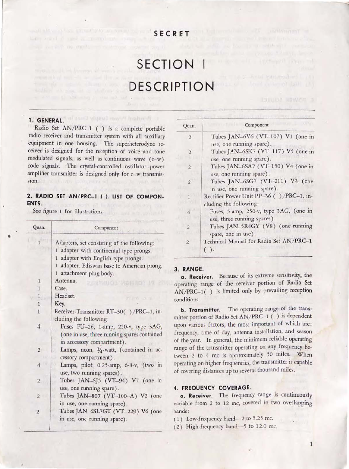
1. GENERAL.
Radio Set AN/ PR
radio receiver and transmitter system with all auxiliary
equipment in one housing.
ceiver
is
designed for the reception
modulated signals, as well
code signals.
amplifier transmitter
sion.
2.
RADIO
ENTS.
See figure 1 for illustration
Quan.
1
1
1
4
2
4
2
2
2
SET AN/ PRC-1 ( l,
Adapter
l adapter with continental type prongs.
1 adapter with English type prongs.
adapter,
attachment plug body.
Antenna.
Case.
Headset.
Key.
Receiver-Transmitter
eluding the following:
Fuses
(one
in accessory compartment).
Lamps, neon,
ccssory compartment).
Lamps, pilot,
use, two running spares).
Tubes
use, one runni
Tubes
in use, one running spare).
Tubes J
in
C-1
( )
is
a complete portable
The
superheterodyne re·
of
voice and tone
as continuous wave (
The
crystal-controlled oscillator power
is
designed only for c- w transmis-
LIST
OF
COMPON
s.
Component
s,
set consisting
Ediswan base to American prong.
FU-26, 1-a
in use, three running spares contained
JAN-6}5
ng
JAN-807
AN
-6S
use, one running spare).
of
the following:
RT-30(
mp, 250-v, type 3AG,
Y<~-watt,
0.25-amp, 6·8-v,
(VT-94)
spare).
(VT-100-A)
L7GT
) /
PRC-1, in·
(contained in ac·
V7
(VT-229)
(two
(one
V2
V6
c-w)
111
tn
(one
(one
Quan.
2 Tubes
usc, one running
2 Tubes
use, one
2 Tubes
use, one running spa
2 Tubes
in
use,' one running spare).
-
Rectifier
eluding the following:
4 Fus
2 Tubes
Te
2
Power
es,
use, three running spa r
JAN-5R4GY
spare, one in use) .
chnical Manual for Radio
Component
JAN-6V6
JAN
running
JAN-6SA7
JAN
5-amp, 250-v, type 3AG,
-6SK7
-6SG7
Unit
(VT-107)
spare).
(VT
- 117)
spare).
(VT-150)
re).
(VT
-211)
PP-36
es).
(VB)
Set
( ) /
(one
AN
Vl
PRC-1.
( ) .
3. RANGE.
a. Receiver. Because
operating range
AN
/ PRC
-1
conditions.
b. Transmitter.
mitter portion
upon various factors,
frequency, time
of
the
year. In general, the minimum reliable operating
of
range
tween 2 to 4 me is approximately
operating on higher frequencies, the transmitter
of
4. FREQUENCY COVERAGE.
variable from 2 to 12 me, covered in two overlapping
bands:
(.1) Low-frequency bancl- 2
(2) High-frequency band- 5 to 12.0 me.
the transmitter operating on any frequency be.
covering distances
a. Receiver.
of
( )
is
of
Radio Set AN/
of
clay,
The
of
its extreme sensitivity,
the
receiver portion
limited only by prevailing reception
The
operating range
PRC-1
the
most important
antenna installation, and season
up
to several thousand miles.
frequency range is continuously
to
5.25 me.
of
of
( )
is
of
which are:
50 miles.
(one
V5
(one
V4
(one
V3
(one
in.
(one
running
/ PRC-1
the
Radio Set
the
trans-
dependent
When
is
capable
in
in
in
in
/
1
Page 14

b. Transmitter.
can
be operated on any frequency between 2 to 12.0
inclusive. Operation
mental crystal f reguency or its
crystal frequency).
the
The
crystal-controlled transmitter
is
effected on either the funda-
Th<:
second
ran~c
harmonic (twice
is
cove
red
bands:
(1)
Low-frequen
(2)
High-frequen
5.
POWER
cy
band 2
cy
SOURCE.
to 5 me.
hand S to 12.0
me.
Radio Set AN/ PRC-1 ( ) operates through its selfcontained power supply, Rectifier Power Unit
/PRC-1,
source
6.
justed
on
and 250. The receiver requires
watts, at
connected
of
from
115
POWER
a.
Rectifier Power Unit
any
INPUT
by
means
of
of
the following voltages: 115,
LlO
volts, 60
to
an
alternatin~
to
250
volts.
current (a-c) power
.
PP-36
( )
jPRC-
a rotary selector switch for operation
approx1m:ately
cycle.
Under key-down condi-
1 can
15?,
PP-36(
200, 220,
tions the power requirement for the transmitter
proximately 210 watts at 1 I 0 volts, 60
tinuous operation, it
frequency be
bet
ween
is
important that the power-llne
50
and 60
Intermittent operation, however, can
40-cycle
current provided the working penods do not
cycles.
cycles
per second (cps) ·
be
e~ected
For
exceed the following time limits:
1)
Transmitter
(
(2)
Receiver
·······································
..............................
..............
.
10
30
minutes.
minmtes.
me,
in
two
)
be
ad.
125
is
ap-
c~n
on
In
order
to
b.
to
age
the power transformer, at least 4 hours must
elapse between
nating curr
NOTE:
Th~:
An)' attempt
supply and might cause irreparable damage
transformer. Check carefully
power is ac.
make this check.
c.
Principal Power Supply Lines in Foreign Coun-
tries. The
light sockets and
are shown in Table I. These
chan~ed
general
at
they
be maintained for the electri
and eguipments
may,
There
feeding
a given area
standard lines. The location
may
possibly
therefore the
in
paragraph
a
d. Table I
volts,
a-c
prevent overheating and possible dam.
succcs~ive
operations
on
40-cycle alter-
ent.
radio set cannot
to
do
so will
Sec
the
pow
er supp
base
any
time
b~:
burn
nmc
in paragraph 33
lies
plu~s
in
du<:
to
wartime cond
operawd
out the
to
on
fuse:
b~:
sure
direct current.
in the
to
the
normally available from
various foreign countri
valu
es
may vary
should hold true since proper supply must
ca
l devices, transformers,
used
by
a given city, town, or area.
of course,
be
be
which
supplied
emergency circuits
do not
chosen
by
these emergency circuits,
usc
for the radio set
line voltage checking procedure outlined
33
should
always
be followed.
is
divided into four columns: territory, d.c
volts, and frequency. Where
an
precedes a number it indicates the type of supply and
vo
ltage
predominatin~.
power
the
power
available
on
how
to
es
or be
itions, but in
in
usc
for
the existing
asterisk (
*)
•
TERRITORY
--
NORTH
AMERICA
Alaska
British Honduras
Canada
Costa Rica
Cuba
Dominican Republic
Guatemala
Haiti
Hondura~
Mexico
Newfoundland
Nicaragua
Panama (Republic)
Panama (Canal
Pucno
Rico
Salvador
Virgin
Islands
2
Zone)
PRINCIPAL
D. C.
L!O
110
110
110, 220
110
220, 125
110,220
110,220
110
110, 220
110,220
110,220
POWER
VOLTS
TABLE
SUPPLY
I
LINES
IN
A.
-
110, 220
*110, 150, 115,230
*110
*110, 220
* 110, 220
*110, 220
110.220
*110,220
*110, 125, 115,220
110, I
*110
110,220
110
*110
*110
FOREIGN
C.
VOl.TS
15
COUNTRIES
,230
-
FREQUENCY
-
60
60, 25
60
60
60
60, 50
60,50
60
60, 50
50,60
60
60, 50
25
60
60
Page 15

TERRITORY
WEST INDIES
Bahamas I'·
Barbados
Bermuda
Curacao
Jamaica
Martinique
Trinidad
SOUTH
AMERICA
Argemina
Bolivia
Brazil
Chile
Co
lombia
Ecuador
Paraguay
Peru
Uwguay
Ven
ezue
la
EUROPE
Albania
Au
stria
Az
ores
ium
Belg
Bulgaria
Cyprus (Br.)
Czechoslovakia
Denmark
Eswnia
Finland
Fran
ce
Germany
Gibraltar
Greece
Hungary
Iceland
Irish Free
It
State
aly
Latvia
Lithuania
Malw
Monnco
Netherlands
Norway
Poland
Portugal
Rumania
Russia
Spain
Sweden
Switzerland
Turkey
United Kingd
Yugoslavia
ASIA
Arabia
British Malaya
Fed. Malay
Non-Fed. Malay States
om
Su11es
D.
C.
VOLTS
'
110
*220
110
220, 110
*220
220, 110
220
110
,220
220
220, 110, 150
220
220, 110, 120
220, 120
*220
220, 120, 150, 110
220, 110
*220, 110
*120, 220, 110
110, 220, 120,
220, 110, 120, 250
440
*220, 110, 150
220, 110, 120
*220
I
10,
125,
220, 110
220, 110
220
220
220, 110
220, 150, 125
110,105,120
*220,
220, 110, 120, 115, 250
*110, 120,
220, 110, 120,
220, 120, 110, 150
110, 220
230,220,240
110, 120
230
125
15~
220,
11~
105
115, 250
25~
160
.
A. C. VOLTS
-
--
115
11
0
110
127
11
0
* 110
110, 220
*220,
225
*110, 220
127, 120, 220
*220
*110, 220, 150
110
220
*220, 110
*2
20
*110
125, 150
*220,
*220, 120, 127, 110
220
*220,
12
7, 110,
11{
*220, 120, 150
110
*220, 110, 115, 127
*220, 120,
220, 127
220,120,115, 110
*110,
*220, 127,
*110
*127, 110, 220
* 100, 105,
220
*220,
*150, 125,.120, 110, 115,
*220, 120
*220
105
110
220, 120, 127
*220, 230, 130,
*220, 120, 110
I
*220, 110, 125
120, 220, 110, 115, 105
*120, 110, 220
*120, 125,150,
*220,
*120, 220, 145, 150, 110, 120
*220, 110
*230, 240,
* 120,
230
230
12
7
11
5,
120, 125, 220, 230
120, 110
110,2
20,120
?OO
127,110
11
12
7, 110, 125
others
220,00
0. 115,220,
135
120,260
, 120, 150
130
,220,
135
FREQUENCY
60
50
60
50
50
40,60
60
50,60,43
50,60
50,60
60,50
60, 50
50
60, 50
50
60
50
50
50
50,40
50
50
50, 42
50
50
50
25
50,
50,
25
76
50
42, 50
50
50
42, 50,
45
50
50
100
42
50
50
50
50,42
50,42
50
50
50, 20, 25
50,40
50
5
0,25,4
0
50,42
50
50,60,40
3
Page 16

TERRITORY
D. C. VOLTS
A.
C. VOLTS FREQUENCY
ASIA-con!"
Ceylon
China
Hawaii
India
Fr.
I ran
Iraq
Japan
Manchuria
Palestine
Philippine Island s
Syria
Siam
Turkev
AFRICA
Angola
Algeria
Belgian
British West Africa
British East Africa
Canary Islands
Egypt
Ethiopia (Abyssinia)
Italian Africa
Cyrenaica
Eritrea
Libya
Somali land
Morocco
Morocco (Spanish)
Madagascar
Senegal
Tunisia
Union
OCEANIA
Australia
New
Victoria
Queensland
South Australia
West
Tasmania
New
Fiji Islands
Society Islands
Samoa
d.
Straits Settlements
North
Borneo
Ind
o China
(Persia)
(P
ort.)
Congo
(Tripoli)
(Fr.)
(Fr.)
(Fr.)
of
South Africa
South Wales
Australia
Zealand
*230
220
220, 110
220,110,225,230,250
110, 120, 220, 240
220, 110
*220, 200
100
llO
220,
220
"'220
*220
110
220
150
120
110
200
230
220,230,240,
*240
230
220, 240
200,230,220
*220, 110, 230
230
230
240, 110, 250
110 •
230
110
230
*110, 200, 220
110,220
230, 220, 110, others
*120, 220, 110, 115, 240
220
220,230
* 100, 110
110
220
220
110, 115, 220
100
"'220, 110
110
* 115, 110,
220
230
240
127, 110
*
200, 110, 220, I
220, 250
* 110, 150
127
125, 110, 270
*230
115, 110
127, 110, 115
*
120
120
110 50
*220,230,2-10
*2-10
*230
*240
*200, 230,2-10
250
*240
*230
120
110
127
10
50
60
50,60
50,
60,25
60,25
50,
25
50
50
50
50,60
60,50,25
50
60
50
50
50
50
50
60
50
50
50
50,40
50
50
50
50,42,45
50
50
50
50
50
50
50
50
50
50
40
50
50
60
50
7. POWER OUTPUT.
a.
Rec
eiver.
25
milliwatt
b.
Transmitter.
mitter is not
2 to
12
me.
The
s.
Jess
than 30 watts
4
power
The
power output
output
of
the receiver is
of
at
any frequency from
the trans-
8.
WEIGHT.
Radio Set AN/P
approximately
as follows:
a.
The
carrying case with about six
Gel is packed in
RC
1
35 pounds.
a
snug
fitting corrugated case, then in a
()
set
The
up
for
operation, weighs
set is packed
pounds
for
export
of
Silica
Page 17

CONTINENTAL
Fig:~re
2.
EDISWAN
Linu cord adapters.
vapor·proof foil barrier, then in a
case.
This unit
is
packed
in
having inside dimensions approximately
R~"·
This
overseas
wooden
resistant liner. One Crystal
containing a set of 47
packed
same
we
a large
packed
kit
packed
9.
in
a similar manner
wooden
overseas
ighs about 76 pounds.
Every
b.
sixth radio set
wooden
case,
spare parts for
case
measures
for export weighs about 270
ADAPTERS
(fig.
A set of molded l
in
the left-hand
The line
PP-36(
with standard
the radio
arc
in
usc,
cord
associated
)/PRC-1
American
set
in countries where other el
it
is
necessary
between the line-cord
crystals
is
case.
This
is
packed
with compartments into
five
radio
21Vsn
x 27Ys" x
2).
ine-cord
accessory
plug adapters
compartment (figs. 2 and
with
is
terminated with a
type
prongs. In order to
to
interpose a suitable adapter
plug and the available
~ccond
an
overseas
box also
Case
CY-86/TRC-JO
corrugated
wooden
27Yf
' x 19" x
has a water-
case
individually vapor-proof
also parked
comp
in
lete
overseas
a spare
inside
Farts
unit
kit,
which
sets.
This
spare
parh
28¥<1"
and
when
pounds.
is
supplied
3).
the
R<.-ctifier
Power
plug
Unit
fitted
usc
ectrical
standards
electric:1l
the
arc
outlet.
a.
The adapter with continental
to
the American plug except that the prongs
type
prongs
is
are
similar
round
and slotted.
b. The adapter with English
similar
to
type
prongs
is
the continental plug except that the prongs are smaller
in
diameter and somewhat longer.
Ed
iswan
base
c. The
type
having radial l
adapter
ock-in
d. The attachment plug
the radio set to standard Edison
is
pins.
body per
of the
mits
base
double-contact
connection
socket
outlets.
of
--~~-l~rl,~&z'
Figure
3.
Adaptur
10. ANTENNA.
The antenna supplied with
in
the left-hand
accessory
ill
left-baud romp.Irtmem.
Radio
Set
AN/PRC-1 ( )
compartment (figs. 4 and
9)
consists of 150 feet of cotton-covered tinned copper
wire, wound on a
is
the wire
is
attached to a porcelain antenna insulator. A cotton
line
order
far
end of the antenna
terminated with a phone tip; the other end
20
feel
long
to
provide a convenient
wooden
is
tied
handreel. One end of
to
the antenna insulator
means
for
to
the support selected.
s<.-curing
the
'
in
5
Page 18

11
. CARRYING
a.
The
made
of
fabric.covered plywood.
CASE
.
case housing Radio Set
AN/PRC-1
The
strongest possible construction consistent
duced weight.
aluminum framework and
receiver, transmitter, and
Set AN/ PRC- 1 ( ) (fig.
sory compartments are provided.
sory compartment (figs. 3 and
1)
Adapters, set.
(
(2)
Antenna.
3)
Headset.
(
(4)
Key.
b.
The
The
interior
of
the case is fitted with an
brackets for supporting the
rectifier power unit
8).
In
addition, two a
The
9)
contains:
right-hand accessory compartment (fig.
contains:
1)
Set spare tubes for receiver.
(
(2)
Set spare tubes for transmitter.
3)
Spare rectifier tube for rectifier power unit.
(
( 4 J Spare neon bulbs.
5)
Spare dial and panel lamps.
(
c. A complete schematic diagram
ANjPRC
cover
12
a.
to
the
- 1 ( )
of
the case.
. HEADSET
Headset
fit
closely to the
is
affixed to the interior
HS-30
HS-
!fig. 6).
30
is
a light-weight headset designed
ope
rator's head.
headset are fitted with special
The
soft
designed to fit lightly in the operator's e
exclude outs ide nois
a headband
made
es. The
of
a thin strip
be shaped to fit the contour
of
headset
the
is
of
steel so
wearer's head. A clip,
( )
case
is
of
the
wit:h
its re-
of
Radio
cce
left-hand acces.
5)
of
Radio Set
of
the
hinged
receivers
of
rubber plugs
ar
cavities to
provided with
tbat
it
can
a~ed
to
~he
headset cord can be attached to the opera-
is
tors
clothmg to relieve the pull and weight
from the operator's
ears.
the left-hand accessory compartment.
b.
For use with Radio Set AN/ PRC- L ( ) , Headset
~S-30
m_
s.
w1th
13.
~oth
IS
CD
.
1n
ca
14. RECEIVER-TRANSMITTER
WITH
of
in the
tro
front
is
supplied with Cord
Plug PL- 55. The impedance
Cord
KEY
a. K
ey. J-37
tens1
CD-605
J-37
on
is
approximately 4000 ohms.
(flg.
7).
is
a standard telegraph
and spacing
mounted on a bakelite base and
- 201-
A.
b.
Cord CD-201- A is 18 inches long and terminates
Plug PL-55. The key, with its mount and cord
rried
in
the left-hand accessory compartment. '
CASE
(flg. 8
1.
a.
Receiver-Transmitter RT-
the
radio chassis and front panel
lugga
ge
fabri
c-c
overed carrying case. All con.
is,
jacks, terminals, and meter are mounted on the
panel.
of
The headset
is
contained in
CD-605 which terminates
of
Headset HS-3
key,
adjustable for
of
the contact arm.
is
fitted with Cord
RT-30( 1/PRC
30(
) / PRC- 1 consists
of
the set mounted
the cord
The
key
- 1
0
is
Fig11re 4.
Antetlll
tl 0
11
reel.
Fig11re
5. Rigbt-b
a11d
aueuory
compartment.
6
Page 19

( 1)
The
receiver portion
of
the radio
set
consists
five-tube superheterodyne receiver designed for
performance reception
signals within the frequency range
(2)
The
transmitter portion
of
a two-tube crystal-controlled oscillator power-ampli-
11er
combination designed for c.w transmission
intelligence within
b. Receiver-Transmitter
on
a sin
gle
panel
receiver
mounted
mitter
the
and
all
on
the left-hand side
and
its components and controls are mounted
right-band side.
of
amplitude-modulated and c.w
the
frequency range
RT
by
means
of
its components
The
separate chassis are attached
of
2 to 12
of
the radio set consists
of
2 to 12 me.
-30(
)/PRC-1
of
separate
of
the panel; the trans-
chas'sis.
and
controls are
is mounted
to the panel with machine screws.
c.'
The
panel supporting the receiver and transmitter
chassis
is
held
in
place
in
the case by means
screws.
Fig11re
me.
of
6. Headset
of
a
high-
of
The
on
six
HS-30.
d. Receiver-Transmitter
with all tub
are held
e.
A complete set
lamps
unit is contained
for
es
and dial lights installed.
in
pla
ce
by
the
receiver, transmitter, and rectifier power
in the right-hand accessory compart-
ment.
RT-30(
)PRC
- 1 is shipped
The
clips
or
clamps.
of
spare tubes, neon famps, and dial
tubes
Figure 7. Key f- 37
7
Page 20

Pig
me
s.
Rectifiel'
Potver
Unit PP-36( ) /PRC- 1
(//ld
Receive~·-Trnmmitter
RT-
30(
)/PRC- J .
15.
RECTIFIER
Rectifier Power Unit PPthe power unit and its
ce
nter compartment
power unit provides a source
plate, screen-grid and bias voltage for both the transmitter
and
voltage for the transmitter,
Full-wave rectification is employed.
for operation
voltages through
All controls, switches, and fuse posts are mounted on
the front panel
connection between the power unit
8
POWER
receiver
of
the power
of
UNIT
PP-
36( )/PRC
36(
) / PRC- 1 consists
front
panel mounted
of
the carrying case.
of
filtered, rect1fied
as
well as a source
receiver,
unit
on
the
adjustment
the power unit (fig.
of
- 1.
of
in
the upper-
Th
e. recti tier
a-c
of
a-c filament
and
power unit.
Provision is made
various
a selector sw1tch.
and
a-c
i~put
9).
Inter-
the receiver
. tnd transmitter is made
in
a polarized plug which
receptacle on the chassis
1
6.
CONTROL
All
operatinJ.: controls, jacks, indicating meter and
fuse posts are mounted
Transmitter
Unit
PP
when .the
operatmg control knobs associated with the rectifier
power unit bear
trol
RT
knobs assoCiated with Receiver-Transmitter
-
30(
S lflg. 9
RT -30(
- 36.( )
h1n
gcd cover
/PRC
letter. designations.
) / PRC 1 bear
by
means
of
a cable ending
fits
into a
of
the receiver-transmitter.
c
orrespondin~
).
on
the front panels
)/ PRC- 1, and the Rectifi
- 1. These items are visible only
of
the housing is opened.
(The
1111111ber
designations.)
of
Rec~iver
er
Power
The
operating con-
Page 21
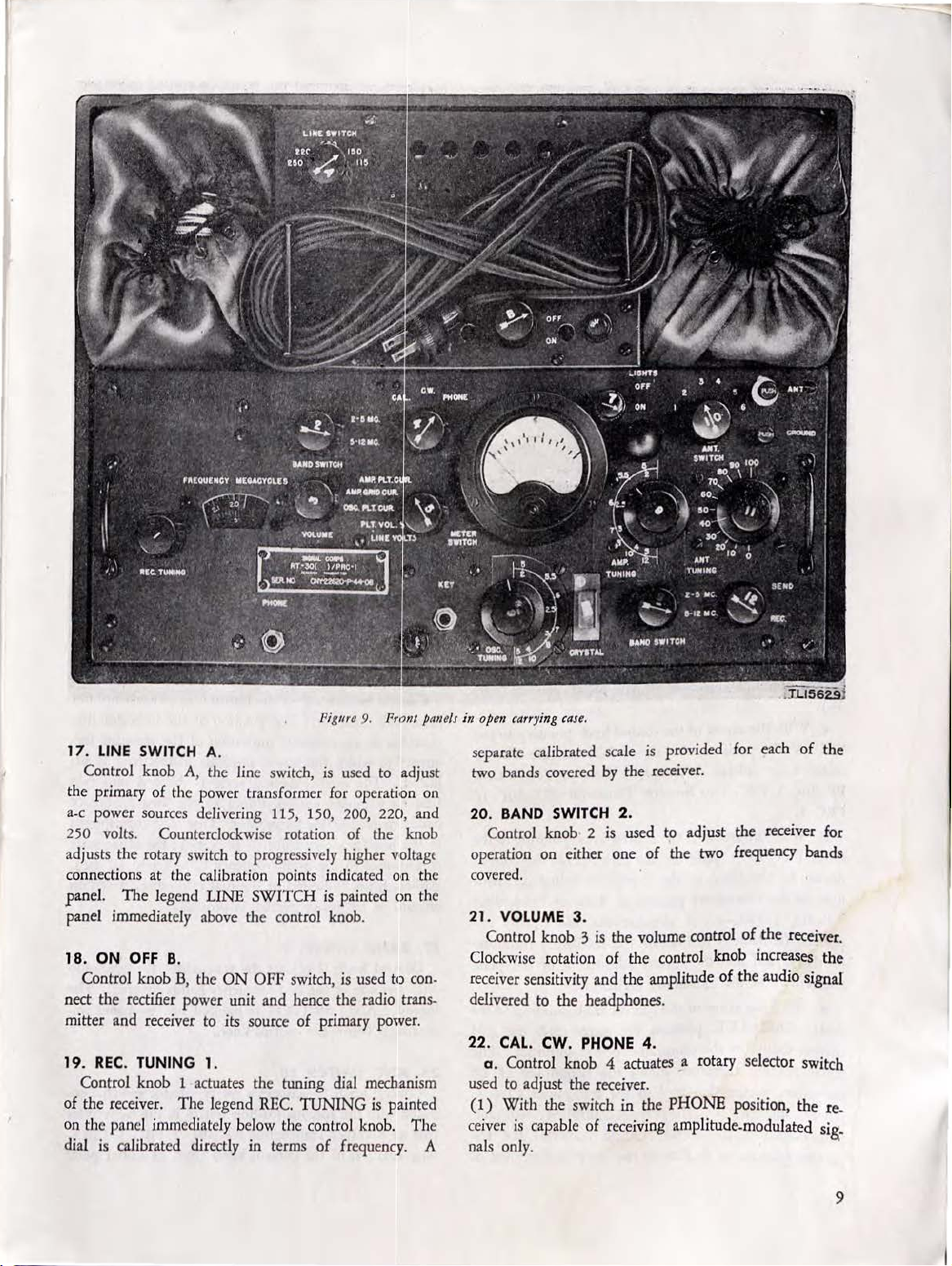
Pig11rc
9.
Prl?nt
panels
17. LINE
Control knob A, th e line switch,
the primary of the power transformer for
a.c power sources delivering 115,
SWITCH A.
is
used to adjust
operation on
150, 200, 220, and
250 volts. Counterclockwise rotation of the knob
pr
adjusts the rotary switch to
connections at the calibration points indicated
pane
l.
The
legend LINE
ly
panel immediate
18. ON
OFF
Control knob
above the control knob.
B.
B,
the
ogressively higher voltag'
SWITCH
ON
OFF
is
switch, is used to con-
painted
on
on
the
the
nect the rectifier power unit and hence the radio transmitter and receiver to its source of primary power.
19. REC
. TUNING 1.
Control knob 1 actuates the tuning dial mechanism
of the receiver. The legend
REC.
TUNING
is painted
on the panel immediately below the control knob. The
dia
l is calibrated directly in terms
of frequency. A
in
open
carrying case.
is
separate calibrated scale
two bands covered
20
. BAND SWITCH 2.
Control knob 2
by
is
operation on either one
provided for each
the receiver.
used to adjust the receiver for
of
the two frequency bands
covered.
21. VOLUME 3.
Control knob 3 is the volume control
Clockwise rotation of
receiver sensitivity
the
control knob increases the
and
the amplitude of the audio signal
of
the
receiver.
delivered to the headphones.
22 .
CAL.
CW.
PHONE
4.
a. Control knob 4 actuates a rotary selector switch
used to adjust the receiver.
(1)
With
ceiver
the switch in the
is
capable of receiving amplitude-modulated
PHONE
position,
nals only.
of
the
the
re.
sig.
9
Page 22

(2)
When
coming signal produces
phones corresponding to the keyed signal impulses.
(
3)
plate·voltage delivered to the receiver is reduced, causing a correspond ing decrease in the sensitivity of the
receiver. Calibration
recep
the transmitter crysta
it
with the dial calibration, and adjusting the dial hair-
line,
23. METER
a.
which connects an indicating meter in various circuits
of
the transmitter. Inserti
circui
control knob.
b.
LINE
nitude
un
it by the
may be set on the correct tap.
delivers direct current, this condition
by the abnormal behavior
33)
.
c.
PLT. VOL. position, the meter indicates
rectified a-c voltage delivered by Rect
P
P-36( )/PRC-1
PRC-1.
d.
O
SC.
drawn by the plate
tube in the transmitter portion
RT
-30( )/PRC-1.
portant
of the crystal and the correct adjustment of the plate
tank circuit
e.
AMP. GRID
cu
rrent drawn by the transmitter power ampliifier.
meter reading therefore shows the magnitu
excitation voltage delivered to the transmitter Class C
power amplifier by the crystal-controlled oscillator.
Simultaneousl
portant function
the switch is in the CW. position, the in-
an
audible note in the head-
When
ti
if
With
With
With
the switch is
on
of a signal of known frequency generated by
necessary
Control knob 5 operates a rotary selector switch
ts
is
(par
SWITCH
shown by the position of the awow on the
AMP.
AMP
OS
PLT. VOL.
LINE
Wi
th the arrow
VOLTS position, the meter indicates the mag-
of
the voltage delivered to the recti
a.c
power source,
the arrow
to Receiver-Transmitt
the arrow
PLT. CUR. position, the meter reads
of
fun<!t:ion
is
to
of
the transmitter oscillator.
the arrow of the control knob pointing to the
CUR
. position, the meter reads the grid
y,
the meter reading pe rforms the im-
of
indicating the correct adjustment
in
the
CAL_.
position, the
of
the receiver is made through
l-
controlled oscillator, comparing
. 40 ) .
5.
on
of
the meter
PLT.
CUR
. GRID
C.
PL
of
the control knob pointing to the
T.
CUR.
VOLTS
so
CUR.
the
If
of
the meter po:inter (par.
of
the control knob pointing
of
the control knob pointing to the
the crystal-controlled oscillator
of
Receiver-Transmitter
A simultaneous and equally im-
indicate the oscillatory condition
in
1the various
.
Jier
power
LINE
SWITCH
the power source
is
m~lde
known
to
tlhe
filtered
i.fier
er
p,ower
R'T
the
tde
Unit
-30(
current
The
of
the
)/
r-f
of
the plate-tank circuit
stage.
f.
With
the arrow
AMP. PLT. CUR. position, the meter reads the plate
current drawn by the transmitter Class C power
fier. Simultaneously, the meter reading indicates the
correct adjustment of the power-amplifier plate-tank
circuit and the optimum degree
antenna coupling system.
24.
OSC
. TUNING
Control knob 6 drives the transmitter oscillator plate-
tank capacitor.
line on
on the panel provides an approximate indication of the
resonant frequency to which the oscillator tank circuit
is adjusted.
two frequency ranges corresponding to the two
quency bands covered by the transmitter.
corresponds to the low-frequency band
the other scale corresponds to the high-frequency band
( 5 to 12
brations, a certain amount
vided.
25.
A
mitter
2
plate-tank capacitor.
provides an approximate indication
quency to which the power-amplifier plate circuit
justed.
frequency ranges corresponding to the two frequency
bands covered by the transmitter.
to the low-freque
correspoq.ds to the high-frequency band (5 to 12
Although not indicated
amount
27. BAND
on
legend
mediately below the control knob.
28
ciated with the antenna-loading system in the transmitter
part
wise rotation
tl~e
knob with the dual-calibrated scale painted
The
me).
LIGHTS
Control knob 7
6.
AMP
Control knob 8 drives the transmitter power-amplifier
Control knob 9 adjusts the transmitter for operation
either one
. ANT. SWI
Control knob J o actuates a rotary selector switch asso.
of
7.
and
receiver panel lights.
. TUNING 8.
The
of
frequency overlap is provided.
SWITCH
of
BAND SWI
Receiver-Transmitter
of
the crystal-controlled oscillator
of
the control knob pointing to the
of
its loading by the
6.
The
relative position
dual-calibrated scale
of
is
(2 to 5.0 me) ;
Although not indicated by the dial cali-
of
frequency overlap
is
the pane l light switch for the trans-
The
po~ition
dual-calibrated scale
ncy
band (2 to 5
by
the dial calibration, a certain
9.
the two frequency bands covered.
TCH
is
TCH 10.
of
the control knob
One
painted
RT-30(
from
of
the indicator line
of
the resonant fre-
is
divided into two
scale corresponds
me);
the other scale
on
the panel i
)/PRC-1.
its initial point
ampli-
the indicator
divided into
fre-
One
sca
is
pro-
is
ad-
me).
The
m-
Clock-
le
lO
Page 23

with the arrow pointing to l dcueases the inductance in
series with the antenna, causing
crease in the effective electrical length
switch points are provided.
Six
SWITCH
the control knob.
29.
Control knob 11 drives the variable capacitor asso-
ciated with the antenna-tuning system in the tramsmitter
part
Clockwise rotation
point with the indicator line engraved on the skirlt
control knob pointing to
capacitance in the antenna.tuning circuit.
3
0.
Control knob 12 actuates a switch which turns the
transmitter
ceiver off when in the
31.
In
elements directly associated with the operation
Set
AN/PRC-1
the Rectifier
panel
a . An extractor fuse post
panel
The
in the primary circuit
is
painted on the panel immediately below
ANT. TUNING
of
the Receiver-Transmitter
SEND REC.
off when
MISCELLANEOUS
addition to the controls mentioned, the folllowing
Power Unil
of
Receiver-Transmitter
of
the Rectifier Power Unit
fuse associated with the extractor post
11.
of
the control knob from its initial
0, results in an increase
12 .
in
the REC. position and the
SEND
MARKINGS.
( ) are located on the front panel of
PP-36(
of
the power transformer. Re.
a corresponding de.
of
the antenna.
The
legend
RT-30(
position.
)/PRC-1
RT-30(
is
provided on the front
PP-36(
)/PRC-1.
otf
and on the
)/PRC-l.
)/lPRC-1.
is
connected
ANT.
of
the
Radio
of
placement
counterclockwise rotation
FUSE, removal
a .new element.
b.
The
Transmitter
jack marked
or
high-impedance output connections are underneath
the receiver chassis.
c.
The
part
of
serted in the keying relay circuit at the jack marked KEY
located on the front panel.
in
re-
d. An extractor fuse post
panel
o(
fuse associated with the extractor post
the plate circuit
fier.
Replacement
through counterclockwise rotation
marked
section
of
e.
A crystal socket
Receiver-Transmitter
above the legend CRYSTAL painted on the panel. The
crystal socket provides
crystal in use, in connection with the crystal-controlled
osciJlator in the transmitter
RT-30(
f.
An
are provided on the front panel
RT-30(
responding legends
a blown fuse
of
the defective fuse, and insertion
audio output
RT-30(
PHONE
key
Receiver-Transmitter
Receiver-Transmitter
FUSE, removal
)/PRC-1
located on the front panel. Low.
used in conjunction with the transmitter
of
the transmitter class C power ampli-
of
a new element. .
is
RT-30(
)/PRC-1.
antenna binding post and a ground binding post
)/PRC-1
immediately to the
ANT.
is
accomplished through
of
the small knob engraved
of
the receiver part
is
made available
RT-30(
is
RT-30(
a blown fuse is accomplished
of
the defective fuse, and
located
)/PRC-1
)/PRC-1
provided on the
)/PRC-1.
of
the small knob
on
the front panel
a connector receptacle for the
part
of
Receiver-Transmitter
of
Receiver-Transmitter
left
and
GROUND.
of
Receiver-
is
connected
immediately
of
the
at
the
is
in.
front
The
in.
of
cor-
of
in
11
Page 24

SECTION
II
INSTALLATION
32. INITIAL
Unpack
damage
compone
a . Radio Set
installed.
with the exception
in place
is
held
b. Five Crystal Holders
upper left.hand compartment, along with the plug
adapters, headset,
is
· shipped inserted in the crystal.holder socket on the
panel
of
c. The spare tubes, fuses, pilot lights, and neon bulbs
are contained in the upper right-hand compartment.
INSTALLATION
33.
AND
RECTIFIER
The
case housing the transmitter, receiver, and rectifier
power unit may be installed in any convenient position.
The most suitable position
when the case
erably on a desk or table
Having selected a suitable location for the
the two clasps with the luggage key and
of
the
accordance with the following steps:
a.
Make certain that the power supply
switch knob B
b. Set LINE
c. Rotate the METER
LINE VOLTS position.
d. Unwind the line cord from the two brackets pro.
on
vided
-36(
PP
long.
e.
Inspect the power source and select a suitable
adapter for the line cord plug
is other than the U.
used
PROCEDURE
.
the equipment carefully to prevent loss or
of
the components. Check against the list of
nt
s in paragraph
AN/PRC-1
The
tubes in the receiver and the transmitter,
by
clips. The transmitter power-amplifier tube
in
place
by
a clamp.
key,
Receiver.Transmitter RT-
POWER
is
mounted on a horizontal plane, pref.
2.
See
figure
1.
( )
is
shipped with all tubes
of
the power-amplifier tube, are held
FT-243
are contained in the
and antenna reel. A sixth crystal
30(
)/PRC-1.
OF
RECEIVER-TRANSMITTER
UNIT
.
for
operation
of
a height suitable for writing.
is
case,
lift
case.
Proceed with the installation exactly in
is
in the
OFF
position.
SW
ITCH
control knob A to 250.
the front, panel
)/PR
C-1.
The
SWITCH
line cord provided is
S.
control knob 5 to the
of
Rectifier Power Unit
if
the electrical system
standards.
obtained
open
the cover
ON
OFF
25
feet
AND
f. Insert the line.cord
OPERATION
plug
(through the adapter, if
needed) in the power outlet and observe the voltage
by
reading indicated
NOTE:
If
the meter pointer swings to either extreme end
of the meter scale the power source delivers direct current.
funher
As a
plug
in
the receptacle. Assuming
to
traveled
the polarity
pointer will now travel
meter scale. Radio
operation on alternating current only.
TEMPI' TO OPERATE
g.
the extreme right
of
Having determined the line voltage through the
procedure given in subparagraph
the meter.
check, reverse
the line-cord
Set
AN/PRC-1
IT
the
polarity
that
end
of
the meter scale before
plug
was reversed, the meter
to
the extreme left
ON
A D-C
of
the line cord
the meter pointer
end
( ) is designed for
DO NOT
POJIYER
f above, rotate the
LINE SWITCH control knob A to the position marked
by
with the input voltage indicated
It
is
not probable that the meter reading will correspond
exactly to any of the input voltages painted
in connection with the
case,
In this
set the switch on the tap nearest the indi.
LINE
SWITCH contro l knob A.
the meter reading.
on
cated voltage.
h.
Remove the headset,
key,
antenna reel, ground wire,
and selected crystal from the upper left-hand accessory
compartment. Insert the phone cord plug in the jack
marked
PHONE;
the key cord plug in
t~e
jack marked
KEY.
34.
INSTALLATION
a.
Optimum performance
lesser extent,
of
antenna and ground installations. Ideally, the antenna
shou
ld
be located in a horizontal plane, at a height
20 to 40 feet above the surface
of
any nearby objects. Further, the plane
should be broadside to the direction in which the trans.
mitter intelligence
be
cut to the following lengths for best transmission and
reception in relation to frequency:
Op
erating frequencies Antenna length
to
2
3 to 7 me
7 to
OF
ANTENNA.
of
the transmitter and, to a
the receiver
is
dependent upon proper
of
is
to be sent.
3 me .................................
...
......................
12
me
·····-······
···
···········
··· .. 50 feet
the earth and clear
of
the antenna
The
antenna should
1
~0
feet
.. 1 00
feet
of
the
AT·
LINE.
the panel
of
12
Page 25

b.
The
length
Figure 10. Rndio Set
of
antenna best suited for optimum
AN/PRC-1
transmitter performance at any frequency within the
range covered is that which will result in proper loading
of
the plate tank circuit
.tier,
with the arrow
the 6 tap, and with the indicator line
pointing to the 0 mark
It
is
realized that this condition
dinarily impossible to achieve
of
the transmitter power ampli-
of
the control knob 10 pointing to
of
control knob
of
the linearly calibrated scale.
is
difficult and or-
in
practice, and for this
11
reason the antenna-tuning circuit has been incorporated
in the transmitter part
/
PRC-1
in
order to electrically lengthen the antenna.
of
Receiver-Transmitter
RT-30(
c. For best results try to locate the horizontal antenna
in such a position that
tion
in
which communication is to take place. Avoid
installing the antenna so that
it
will be broadside to
it
points toward tbe de.
the
direc.
( ) iiiJtnlled for oporntion.
of
sired direction
communication. A convenient means
to determine the correct orientation
antenna
is
to locate
it
for optimum reception from a
transmitter located in the same part
which you wish to transmit.
d.
It
is
realized
stall
an
antenna meeting any of the requirements out-
lined. In such cases,
that
it
will often be impossible
it
is
following expedients be used, bearing in
vantages and disadvantages
)
(
1)
The
antenna wire may be laid upon the ground,
provided the ground
ment
of
the wire
of
the transmitter is reduced, and
is
relatively
of
is
not wet. In this case, conceal-
load the plate tank circuit
amplifier properly.
of
the horizontal
of
the world to
suggested
that
one
mind
each.
easy.
The
potential range
it
may be difficult to
of
the transmitter power
to
in-
of
the
the ad-
13
Page 26

(2)
If
antenna
sibility of
ever,
the.
the building is of
may
be
instaJled in
concealing the wire
wire
may
be
laid
wooden
side.
upon
Ordmanly,
is
not
the
c?ns~ructio
n
the
very
good. How.
course
of the mold.
ing or other decorative trim. . . . .
(3)
It
may
sometimes
antenna or abandoned wire
poses.
of
people
accustom
e
tenna
the
antenna
antenna
This opportunity is good from the
concealment or disguise of the antenna wue,
in
the neighborhood will
ed
to
seeing the antenna. In
ver,
it will
Jead.in
be
is
connected
wire from its point of connect
to
its point of entrance
is
not
wire at the antenna
supplied with
lead-in
(
4)
The antenna wire
Radio
wire.
roof of the building provided the roof
is
of
wood
or other
too,
the potential range of the
duced, and
conditions
power amplifi
(
5)
vided
event that the
The
that
it
may
in
the plate tank circuit of the transmitter
er.
use
of a vertical antenna IS permissible pro.
it
is kept
equ
try to support the
building
etc.)
whi
by
ch
means
should
erties of a vertical antenna are
those of a horizontal antenna. Optimum dir
will
be
obtained, however, when the antenna
on
the side of the building
the transmitted intelligence
e.
A great deal of reliance
ity
nod
genu
must be
training of
examined
instnllation that c
f.
If
possible, a ground connection
a water pipe, steam pipe, radiator, or
s stem
connected
y . I . . d
a good ground will often
Th
g.
esame
an
. d . connected to the binding post
t
recep
1011,
an
tS .
front panel of R
immediately to the left
ground
is
is
used
for both tr
connected to the binding post
Receiver-Transmitter
be
possible
once
to
used
have
utd1ze
for other
lon_g
th1s
necessary
in
to determine whether the an.
to a
radio
use,
simply
and
receiver
substitute
in
to
the building.
disconnect the l
the
Set AN/ PRC-1 ( ) , using it
may
be
laid
on the surface of the
is
nonm
eta
lli
c construct
trans~itter
be
difficult
to
obta10
proper
. _ _
clear
of
ipment is to
antenmt
away
nearby
be
objects.
located
from the si
of a short pole (broom
be
nonmetal!ic. The directive prop-
jrtcin
the
very carefully.
ircumstances
consider
g the direction
is
to
be sent.
must
operator. The possibilities
Select
permit.
be
ably
placed
the
sho
uld
any
to
the
eartl1.
na is
leo
eceiver.Transmttter
of
RT
-30(
This is important
resLut
m tn
crease
used
for both tr
RT-30( ) /PRC-
the legend ANT.
ansmission
and
on
the front panel of
)/PRC-1
immediately
ansm1sston
receptiOn,
an
existing
s~an
dp?inl
since
case,
use.
Follow
ion
at the
If
ead-in
antenna wire
not
wet,
ion.
w
ill
be
loa~wg
In the
in a building,
de
of the
~an~le
,
l
ess
ectiv
is located
in
which
on
the in.
best
antenna
be
made
other m
etal
r~n~e.
on
T~e
the left of the legend GROUND.
,
the
pos-
pur-
smce
been
how.
the
as
and
Here,
_re.
cane,
than
ity
to
lic
since
and
the
same
and
to
35. ADDITIONAL INFORMATION.
a.
In
the
event that operation
reception,
receiver
along the
b. In
for long distance
c.
l
ected,
if n
36.
a.
in
stallation of the set
prepare the set f
(1)
power
a
cated
(2)
the
( 3)
knob B so
( 4) Assuming
was
in
g should
(5)
fair performance
with
an
antenna
floor
or dropped out of a window.
many
cases a 40
transmission.
No matter what
arrange it
so
type
that it
ecessary.
PREPARATION OF
Preliminary Preparations. Having completed the
as
or
usc
as
Set
the
UNE
SWITCH control
unit)
to
the corr
by the m
Set
arrow
Set
set
eter reading.
the
METER SWIT
points
the
rectifier
that
the
th
to
the
proper
be
appr
lo
the
PLT.
power
arrow points to the
at
the LINE SWIT
input voltage
oximately
Allow the equipment
period of approximately 4 minute
b. Checking Receiver.
(1)
Set
control
(2)
Set
(3)
Set
(
4)
Rotate control
the
until
static)
is hea
( 5)
Rotate control
the
eve
nt that the r
(
c-w
) transmitt
binations will
tuned to
heterodyne whistle
adjust control
knob
12
control
knob 4 to
control knob 2
knob 3 in
background
rd
in
the head
noise
knob
eceiver
er,
the characteristic dot and dash com.
be
observed.
speech-modulated
wi
ll
knob 4 so
PIIONE position. The h
perm
appear, thus
modulated sig
(6)
Repeat steps
2 adjusted so that
itting
nal
s.
(2), (4), and
its arrow points to the 5-12
mark.
1
c.
Checking Transmitter.
( 1) Disconnect the antenna.
(2)
Set cont
(3)
Set control knob 4
rol
knob
12
position.
(
4)
Insert a
crys
tal holder
is
concerned only with
can
be
obtained from the
about
10
feet
long, strung
or
50
foot
antenna
is
adequate
of antenna installation
can
be
dismantled quickly,
SET
FOR
USE
.
described
in
paragraph
33
follows:
knob
A (rectifier
ect
input volt
a,ge
tap
as
CH control knob 5
VOL.
position.
unit
ON
OFF switch control
ON
pos
ition.
CH control knob A
tap,
the meter read.
1 ,000
volts.
to
run
through a warm-up
s.
to
the REC.
position.
the CW. position.
to th
e 2-5
MC.
mark.
the
clockwise
direction
(atmospheric and man.made
set.
1 until signals are h
ea
is tuned to a continuou
In the event the r
ece
transmitter, a continuous
be
heard. In the latter
that its arrow points to the
eterody
ne whistle should dis.
reception
to
tl1
to
either the CW or PHONE
in
of the amplitude.
(5)
with control knob
e SEND position.
the
crysta
l holder
is
se.
above,
indi.
so
that
rd. J n
s-wave
iver
is
case,
MC.
socket
14
Page 27

provided on the front panel
RT
-30(
)/PRC-1.
NOTE:
The
tr~nsmitt
mental crystal fr('quency
a 2.3-mc crystal were used,
erated
at
either 2.3 me
(
5)
Set control knob 5 to the OSC. PLT. CUR- posi-
tion.
(
6)
Set control knob 9 to either the
MC. point
in
cr
is operated at either
or
•
accordance with frequency of the crystal
of
Receiver-Transmitter
its second h:wnonic.
the
transmitter could be op-
or
4.6 me.
2-5
the
f~tnda
Th~ts,
Me.
or
if
5-12
selected.
(7)
Adjust control knob 6
points to a calibration point close to the
so
that its indicator line
frequel!lcy
of
the selected crystal or its second harmonic.
8)
With
(
the key depressed, rotate control knob 6
quickly in both the clockwise and counterclockwise di-
of
rection over a few degrees
dip
of
the meter pointer
that the crystal-controlled oscillator
the arc until a pronounced
is
observed. This indicates
is
operating.
(9) Set control knob 5 to the AMP. PLT. CUR. posi-
tion.
(10)
Adjust contro l knob 8 to a calibration point close
:sec
to the frequency of the selected crystal or its
ond
harmonic.
(11)
With
the key depressed, quickly rotate control
knob 8 in both the clockwise and counterclockwise di-
of
rection over a few degrees
the arc to the point where
the meter pointer indicates minimum plate-current drain.
12)
Hold
(
bottom contact touches the
post marked
a neon lamp by its glass
metal part of the binding
ANT.
If
the transmitter
rectly, the neon bulb will glow showing an
CAUTION:
Do
not attempt any
bulb so that its
is
operating cor-
orange color.
chc.'Ck
on the
transmitter while located in a hostile area unless
it
you
closed.
work
are
on
Ac-
you have tried without success to make
during actual operations. Remember
the
air
whenever the transmitter key
complish any
in
the shortest possible time.
11ecessary
checking
is
of
the transmitter
38.
USE
OF THE RECE
IVER
.
Under normal conditions, the receiver will render its
best performance with the set adjusted
tion (control knob 4 in the
a.
Adjust the VOLUME
c-w
position).
CONTROL
for
knob 3
c-w
recep-
in
clodrwise direction until a rushing noise is heard in the
headset.
b. Tune the receiver
ING
control knob 1 is turned rapidly, the desired station
may
easily be passed over.
SLOWLY.
If
the REC. TIJN-
c. Tune the receiver over the band with the left hand.
Keep the right hand on the volume control knob, ad-
of
justing the volume and hence the sensitivity
the re-
ceiver to an optimum level.
d. K
eep the headset on the
receiver e
e.
ar pieces
fitted into the ears.
Having located the desired station, reduce
hea
d w ith the
rubb
or
er
in-
crease the volume to a level that provides the best intelligibility.
f.
If
the desired station is transmitting speech-modu-
lated or tone-modulated
sign~ls,
phone reception (control knob 4 on
If
the desired station is transmitting·
control knob 4 on the
g.
Always search for the desired station with the set
adjusted for
h.
c-w
In
the event that the station received ts bemg
CW.
reception. . .
jammed either through accident or intentional
sign,
it
is
sometimes possible, through careful
lation
of
the receiver tuning, to attenuate the
adjust the set
PHON~
position.
c-w
stgnals, leave
for
tele-
position).
enemy_
de-
_mam~u
Jailll~tng
signals sufficiently to permit the intelligence trans.llllttecf
by the desired station to be copied. . . .
i.
Copying signals through bad
that can be accomplished by concentrating attenbon
atmo~phencs
~~a
trtck
e_n-
tirely on the signals. Since the signals have a de.fimte
pitch, try to
t1111e
the hearing to hear only sounds
of
_the
signal pitch. In this connection, observe that the pttch
of
c-w
signals can be varied over a
n~rrow
range
through detuning the receiver very slightly from
resonance.
a
37
. OPERATION.
Having
in paragraph 36,
tual operation
the transmitter is
be reduced to
prepared the equipment for use
it
can now be put into operation.
of
the receiver is simple; operation of
a trifle more complicated, but
a series
of
integrated steps provided the
as
outlined
it
Ac-
can
instructions given in this manual are carefully fol!lowed.
Memorize each
ment a number
ditions. Learn
maxunum performance
be obtained and the chances of being detected will
part
of
the operation. Use the equip-
of
times under simulated service con.
how and
tuhy
the equipment works; the
of
which the set is capable will
be
reduced.
39.
PREC
AUTIONS
IN
OPERATION OF
RECEIVER
a . Tune slowly.
b. Keep the volume adjusted to
level without having the signals audtble except
th_e
highest
p~ssible
10
headset.
c. Always search for the desired station with the set
c-w
adjusted for
d.
Do
not try to receive c-w signals with the set ad -
justed
for
e.
Do
not
se
nd
position.
reception.
phone reception.
try
to receive with control
knob
12
.
the
in the
15
Page 28

Pig11re
11.
Rece
iving
sccJio11
of
from
prmol
of
Receive
Transmillcr
40. RECEIVER
If
the frequency indicated
not correspond
bein~
received,
Lo
the
manner described
CALIBRATION.
the
known
receiver
below
R'J:-30()/PRC
on
the
- l.
receiver
frequency of the station
dial
can
be
_corr~·e~
so
that the dtal wtll mdtcate
the correct frequency. The following calibration
may
also
be
used
if
the receiver
is
to
be
tuned
station and left in that position, provided a
the transmitted frequency
rection
of
this
type
The receiver part of Receiver-Transmitter
PRC-1
age
is
calibrated against a radio-frequency (:r-f) volt-
of known frequency generated
is available. A
is
known
as
receiver
by
che~
RT-30(
the
r·
dial
does
in_
method
to
one
c:rystal
or
~or
caltbratton.
crystal-~on
trolled oscillator in the transmitter. When the recetver
is
set for the reception of
the receiver
frequency
the set for
ceed
is
adjusted to a zero-beat condition with the
of the transmitter oscillator. Having prepared
use
in
with the calibration of the receiver in the· follow-
c-w
accordance
signals,
the
freg
with paragraph
~
uency
36,
pro-
ing manner:
a. Insert a
frequen
b.
Set
c.
Set
d.
Set MET
PLT.
CUR
e. Adjust control knob
the
band
check
is
f. Adjust control knob 9
band
covering the frequency at
check
is
g.
D
6 for minimum plate-current drain
meter.
crysta
l in the
cy
at which the calibration
cont
rol knob 4 to the
control knob
ER
SWITCH control knob 5 to
.
pos
ition. .
12
crystal
to the
2
so
covering the frequency at
to
be
made.
so
that i
to
be
made.
epress
the transmitter
This condition will
key
be
holder socket
check
CAL.
position.
REC.
position.
is
to
be
tihe
of
made.
OSC.
that its arrow P?tnts.
which
the caltbratJon
ts
arrow
poinl~s
to
which
the caltbratton
and adjust control knob
as
indicated
manifested
by
by.
a shght
the
~he
the
dip
in
the
meter
pointer
is
oscillating.
Rotate
iver
the
frequency
slowly
of the
control
is
just audible.
with
the
REC.
frequency
h.
the r
ece
the
receiver
i.
Rotate
dicates
the
knob
vicinity
pitched whistle will
which
will
rise
and fall and then
is
slowly
turned. The point
peaks
is
zero beat.
dial should indicate the
inserted
crystal.
incorrect, the hairline
screw
adjusting
just
the dial opening
bration
the
frequency.
CA
UTI
ON:
Do
in
a hostile
area
Calibration of the
transmitter with the
by
enemy
direction finding units.
of
4
1.
USE
OF THE
the
)/
art. Detection
down
mitted
Remember
key
tune-up
that the transmitter
is
closed.
can
process
quickly.
Meaningless
during adjustment attracts
of
lar transmission. A great deal of time can
and
will
indicat
e that the crystal
knob
3 until the background
Do
not attempt
lhc
volume
control turned full on.
TIJNING knob 1until the dial
of the inserted
so
that the dial calibration
of the inserted
be
observed,
At this position the
frequency
If
the dial
must
be
to
the right of the lower edge of
so
that it
is
not attempt
unless it
receiver
conseque
TRANS
M ITTER.
Direction finding
be
avoided
is limited, and
more
crystal.
crystal,
the
rise
again
midway
between the
REC.
as
stamped
cal
ibration
adjusted
in
line with the dial cali-
lo
calibrate the receiver
is
absolutely
involves
is
by
the
nt risk of detection
is
011 tbe
is
a highly
successfully
messages
keying
of the transmitter
attention than a
through preadjustment of the controls to an approximate
position
determined
by
past
experience
as
to
Pig11rc
12.
Tr,msmiller
'fr.m
<miua
sectio11
R"f
of
J(l(
/ro111
)IPRC
panel
I
noise
to
calibrate
By
rotating
is
in the
a high-
frequency
as
the
TUNING
on
found to
means
of the
necessary.
use
of the
air
whenever
developed
if
the
are trans-
be
saved
and
observa
of
ReceiviT
in
in-
of
knob
two
the
be
key-
regu-
-
16
Page 29

•
tion. Before taking this set out on its mission, use it
of
a number
phasis cannot be placed upon the need for fanoiliariza.
tion with its operation before tactical
tual antenna installations in several locations; operate
the equipment under the conditions to be expected in
service use.
lowing tune-up data
sible, memorize it.
Crystal /rcqtl(mcy
Put the transmitter on the air following the procedure
given below:
a.
Select a crystal of the desired operating frequency
or
Y:z
the desired operating frequency (fundamental or
harmonic operation). Insert the crystal in the crystal
holder socket provided on the front panel of Receiver.
Transmitter
b. Turn the
position.
c.
Set control knob 4 to the CW. or PI
d. Turn control knob
sired
operating frequency.
e.
Set the METER
AMP.
GRID
times on practice tests. Too much em.
use.
Prepare a transmitter Jog so that the fol-
is
immediately available.
TR
ANSMITTER
a.
fundamental
b. harmonic
a.
fundamental
b. harmonic
a.
fundamental
b. harmonic
a. fundamental
b. harmonic
a.
f undamcntal
b. harmonic
a. fundamental
b. harmonic
RT-30(
)/PRC-1.
SEND
REC. control knob 12 to
LOG
Approximate dial settings
OSC.
TUNING
AMP.
lONE
9 to the band covering the de.
SWITCH
CUR. position.
control knob
Practice ac.
If
TUNING
the
SEND
position.
~>
to the
f. Depress the transmitter key and rotate control knob
!'i
for maximum grid current as indicated by the meter.
At
this point
the dial calibration.
it
should correspond rather closely with
g.
Set the METER
AMP. PLT. CUR. position.
h. Depress the transmitter key and rotate control knob
8 for minimum plate current drain as indicated by the
meter.
i.
With
the transmitter key depressed
knob
10 adjusted so that its arrow points to No. 1
pos.
the calibrated scale, rotate control knob 11 clockwise
from zero position.
of
control knob 11 the plate current drawn by the
transmitter power-amplifier tube should increase to
proximately 75
dicate such a plate-current increase, return knob 11 to 0
and adjust control knob 10 so that its arrow points to
of
No. 2
clockwise again.
crease in the plate-current drain,
continue the
3,
4,
5,
and 6
knob 11.
proximately
current. Repeat these adjustments until the
plate current
been rotated too far clockwise, the minimum plate cur.
rent will begin to decrease
that two factors are involved in respect to the antenna
tuning process: operating frequency and physical length
of
the antenna.
quency, the greater will be the amount
needed to load the antenna (control knob
either the 1, 2, or 3 position).
erly loaded, the plate-current reading should be ap.
proximately 75 to
more than
properly matched to the output circuit
mitter. A mismatch will cause a pronounced decrease
in efficiency and may damage the transmitter power out.
put tube.
antenna will vary with each installation, adjustment
control knobs 10
the extent that past experience and
the probable characteristics
rna.
the calibrated scale, then rotate control knob
tuning process, progressively utilizing taps
of
When
75
ma, retune knob 8 for minimum plate
is
at least 75 to 100
In
100 ma.
Since
SWITCH
At
some point during the rotation
If
the meter reading does not
If
the meter does
knob 10 in connection with the control
plate current has increased to ap.
as
general, the lower the operating fre.
100 ma.
If
it
it
is probable that the length
and
11
can be approximated only to
control knob 5 to the
not
it
will
rna.
knob 8
The
does, the antenna
of
is
retuned.
With
the antenna prop.
meter must
ability
the antenna will allow.
A keying monitor system is provided so that an audio
tone will be heard in the headset when the transmitter
is
depressed provided control knob 4 is adjusted to
key
either the
TEMPT
4
IN
42.
a.
the transmitter does not blink the lights
rooms and throughout the house
CW. or
TO
THE
CAL.
SUMMARY
Be careful, when sending after dark, that keying
PHONE
position. DO
TRANSMIT JlfiTH CONTROL KNOB
POSITION.
OF
INSTRUCTION
S.
or
building.
and
with control
indicate an in.
be
necessary to
minimum
If
knob 10 has
Noti
of
inductance
10 adjusted to
not
read
is
not
of
the
trans.
of
the
in
judging
NOT AT-
in
adjoining
This
may
of
ap-
in.
ll
ce
of
17
Page 30

lead
to
detection
blinking
suspend operation until everyone has gone to bed and
the building is dark.
is
power service. Remember, lights blinking
ing
that radio transmission
in
is
the result
will suggest to enemy agents
b.
Do
not
the CAL. position.
Do
not
c.
of
the
equipment.
noticed after a few tentative dashes
This
blinking cannot be cured and
of
a poorly-wired building
is
taking place.
attempt to transmit with control switch 4
attempt to transmit with control switch 12
If
serious light-
or
inadequate
in
a build -
or
enemy personnel
or
dots,
in
the REC. position.
d. Handle the crystals carefully.
e.
Make certain that
ANT.
TUNING
limum matching
of
f. Adjust the contact arm
clearance between
contacts
attendant to keying the transmitter will be much louder
and might result
sonnel to your activities.
of
the key are too far apart the clicking
ANT.
SWITCH
knob
11
have been adjusted for op-
the transmitter to the antenna.
of
the key for minimum
knob
it and the other key contact.
in
calling the attention
of
10
and
If
the
noise
enemy per-
18
Page 31

SECTION Ill
FUNCTIONING OF
43.
RECE
IVER
.
The
receiver uses five lubes, two
in
double-purpose type,
20),
designed for the reception
signals (speech
within the frequency
frequency range
(low-frequency band 2
5
to
12
me)
suitable positioning
hy a control knob located on the front panel
ceiver.
i~
of
gear system by a control knob located on the front panel
of
through the
circuit which
means
the
fier uses two permeability-tuned
Tuning
accomplished through capacitance variation by means
a three.section ganged capacitor driven through a
the receiver. Reception
of
a control knob located on
receiver.
or
is
either
of
in
corporation
is switd1ed into or out
The
a superheterodyne circuit (fig.
tone-modulation) and
range
of
covered in two overlapping bands
to
5.
25
of
which
is
of
a rotary selector switch actuated
the receiver to any desired frequency
of
c.w signals
of
intermediate-frequency
of
which are
of
amplitude-modulated
2 to 12 megacycles.
me, l1igh-frequency band
brought into use through
is
accomplished
a beat-frequency oscillator
of
operation
the
front panel
(i.f)
i.f
transformers
c-w
of
of
signals
The
the re-
by
of
ampli.
PARTS
i.f
resonated to the 455-kc,
the
design
attainment
selectivity, simplicity
undesirable characteristics (image respons
tion).
44.
suitable adjustment
up
antenna coil
18 (high-frequency band) which together with capacitor
Cl7A
fier Tube
tively connected in the circuit through the action
receiver band switch
trimm
high-frequency
the
cuits
of
the receiver has been planned to assure
of
high performance reception (sensitivity,
of
R-F
AMPLIFIER
With
switch SW3
by
the
antenna
17
constitute the
JAN-6SG7(V
er
capacitors used
end
r-f amplifier stage will track with
of
the receiver. C1 7 A, which
STAGE
in
of
control knob 12,
is
transferred inductively from the
to coils
input
SW7. C15 and
of
each
channel frequency.
control) and the absence
.
the RECEIVE position through
the
16
(low-frequency
grid circuit
3).
Coils
to
align the
of
16
Cl6
input
the
two bands
is
of
and
the
one section
The
the
e,
drift. radia.
signal picked
band)
the r-f ampli.
18
are adjustable
circuit
other
and
are selec.
of
the
at
the
so
that
r.f
cir.
of
the
of
LJ
RECEIVER
r--
R.F:
AMP
-
MIXER
osc
,_.._
I.
F.
AMP
r--
OET
1--
AUDIO
AMP
:)
I
B
FO
./
TRANSMITTER
..__
1--
CRYSTAL
osc
diagrmll
of
Radio
Set
POWER
SUPPLY
TL
AN/PRC
c
15633
- 1 ( ) .
19
R.F.
AMP
Pig11rc 13. Blork
Page 32

three-gang tuning capacitors,
the REC.
circuit
which
signal
its corresponding plate-current change is coupled into
either
band),
Bias for tube V3
current through resistor R 16 and the variable
tiometer
control knob
means
applied to tubes
sensitivity
needs.
quirement for V3 when
R14
connection with the screen-grid circuit
C19A functions
plate
V3 and V5.
45.
TUNING
is
resonated to the frequency
is
impressed upon
is
amplified in the tube
19
(high-frequency
depending upon the position
Rl7. Rl7
of
controlling the magnitude of the grid bias
of
Rl3
and R15 serve
of
V3. C19B bypasses the screen-grid circuits of
CONVERTER
control knob so that the input grid
is
obtained through the
is
adjusted by means
3.
The
function
V3
and V5, and therefore to adjust the
the receiver to correspond to prevailing
serves to provide the minimum bias re-
as
as
a bypass capacitor to ground for the
STAGE.
a. Mixer. Since tuned impedance coupling
r.f
between the
19
(high-frequency) and
tively connected
together with capacitor C17B serve
of
the mixer stage.
grid
of
tube
R18 serves
plate current Bowing in tube V 4 is a complex function
of
the signal voltage and the voltage derived from the
local oscillator.
b.
Oscillator.
the cathode, oscillator grid, and screen grid
plus the frequency-determining constants
grid
tank circuit.
prised
of
frequency) selectively connected
SW7 together with C17C.
trimmer capacitors used to align the
oscillator at the high-frequency end
bands. Coils
frequency) are connected in the cathode circuit of tube
V 4
so
that the cathode, oscillator grid and screen grid
V4
function
age
of
the oscillator frequen
the capacitance variation
tronically with the signal voltage.
quency,
of the first i.f transformer
or
amplifier stage and the mixer stage, coils
in
the
The
V4
(JAN
as
a grid bias resistor
The
local oscillator is comprised
The
coil
113
(high-frequency) and
111
(high-frequency) or
as
an electron-coupled oscillator. The volt-
i.E
( 455 kc)
is
adjusted by means
of
the desired signal,
the
grid
of
tube V3.
in
the normal fashion and
band)
or
110
(low-frequency
of
switch SW7.
Bow
of
of
R17
is
to provide a
the
cathode current
a voltage divider network in
LlO
(low-frequency), selec-
circuit through switch SW7,
as
signal is impressed upon the
6SA7) through capacitor C22.
for
oscillator tank circuit
is
of
V3 and V5.
the input circuit
the tube.
of
of
the oscillator
114
in
the circuit throu
C24
and C25 are adjustable
grid circuit
of
each
of
112
cy,
as
determined through
of
C17C, is combined elec-
The
difference fre.
is
coupled to the primary
T!.
(26
and
(27
The
of cathode
poten-
VOLUME
minimum.
is
used
The
of
tube V 4
is
com-
(low-
gh
of
the
the two
(low-
of
115
are the
of
padding capacitors used in the grid tank circuit
oscillator to maintain a constant frequency differential
between the oscillator voltage and the signal voltage,
ive
of
irrespect
circuit by
46.
1-F
The
signal, after having been
frequency ( 455
the first
fixed
ceramic capacitor. However, resonance,
determined and adjusted over a narrow range by means
of
a core
is
adjusted, with respect to
The
rod.
116,
the secondary
lady shunted
condition
narrow range by means
coaxial position
116,
by a threaded rod.
tween the
where
it
sultant plate current
i
second
through the
.f
connection
amp
lifi
er
47.
SECOND
The
signal is coupled inductively from
whi
d1
is
former
trol
(JAN-6SL7)
as
serves as the plate-load resistor for the detector tube
and
48. A-F
_grid
R28 ser
bias through the flow
V7 functions as a class A audio ampldier
audio component
fashion.
the output transformer
connected for use with a high-impedance headset, serv
as the plate load
capacitively coupled to the plate circuit.
ceiver is connected for usc with a low-impedance head-
T2.
grid
a grid-leak detector in connection with R24. R27
C38 serves
The
audio component
of
tube V7 (JAN
ves
the amount
Cl7C.
AMPLIFIER
kc),
i.f
transformer
of
powered icon, the toaxial position of which
signal is transferred inductively from L
of
by
a fixed ceramic capacitor.
of
116
is determined and adjusted over a
of
which,
grid
and cathode
is
amplified in the normal fashion.
transformer T2.
flow
of cathode current through R23 in
with
the
resistor
stage.
DETECTOR
the secondary
The
signal is impressed between the con.
and cathode
through capacitor C34. V6A functions
as
an
AMPLIFIER
as
the
grid
of
the signal
The
plate
of
of
tube V7,
of
capacity inserted
STAGE.
~onverted
is
coupled to
Tl.
115
transformer
of
a core
is
The
is
coupled to primary
The
STAGE.
of
the permeability-tuned trans-
of
V6A one-half
r-f
bypass capacitor to ground.
STAGE
of
the signal
-6]5)
return for V7 whtch recetves tts
of
cathode
V7
is
T4
which, when the recetv
115,
the primary
Coil
115
is
by means
Tl,
which
of
powered icon, the
adjusted with respect to
signal is impressed be-
of
tube V5
bias for V5 is obtained
network
(JAN-6SK7)
utilized in the r.f
.
is
coupled to the
through
is
amplified in
coupled to the
and
~39
curr~nt
t~roug~
the headphones are
When
of
the
in
the
to a new
of
shunted by a
of
11 5
is
of
a threaded
15
to
is
simi.
The
resonant
The
re-
117
of
the
117
to
118
of
tube V6
an~
R~9.
R30.
10
whtch the
th~
normal
prun~ry
~f
er
JS
es
the re.
20
Page 33

set, the audio output
output transformer
neath the receiver chassis.
49.
BEAT-FREQUENCY OSCILLATOR.
Tube V6B, one-half of tube
transformer
The
are permeability tuned L19, shunted
C35. R25, in connection with C36, functions
grid leak bias source for tube V6B.
low-impedance
bleeder resistor to limit the amplitude
generated
voltage generated
coup led to the
capacities
50.
TRANSMITTER.
The
lator
coupled capacitively to a class C power amplifier.
a.
plate type, with the crystal connected between the grid
of
tube
capacitance
capacitors
through the action
lower than that
slight amount
the harmonic operation
a grid leak bias resistor.
pedance path to ground for the heater circuit of
The
frequency-determining constants
are: the crystal, and variable capacitor
connected
band) and L2 (low.frequency band) through the ac.
of
tion
for the screen grid
impedance path to the cathode for
the screen grid.
b.
The
tank circuit
The
output is only slightly decreased when the plate
tank circuit is tuned to the second harmonic
crystal frequency. Because
the circuit affords (isolation between the crystal and
output circuit), the oscil!ator is stable and is
ceptile to changes in tuning. Provision is
selective insertion
determine visually the magnitude
by
Vl.
voltage since the capacitor provides a low-impedance r.f
T3,
frequency determining constants
r-f
by
the beat-frequency osciltator.
of
tube V6A and
transmitter consists
of
the regenerative type, the output
The
crystal-controlled oscillator stage is of the grid.
Vl
(JAN-6V6)
(L-C)
C2
and
of
in
parallel with coil
SWl.
R3 serves as a voltage-dropping resistor
oscillator supplies high output when the plate
is
resonated to the frequency
C4B is used to protect the meter against r.f
is
laken from the secondary
T4.
These connections are under.
V6
(JAN-6SL7),
functions
bypass to ground. R26
by
i.f
combination comprised
C3, selective
of
of
positive feedback and thus improve
of
as
a beat-frequency oscillator.
of
the oscillator
by
.fixed
ca.pacitor
C37 functions
serv·es
of
the
r.f
-voltage
The
the beat-frequency oscillator is
system through the interei<ectrode
B.
of
a crystal.controlled oscil.
of
which
and ground.
ly
SWI,
is
tuned to a frequency much
the crystal in order to introduce a
of
the oscillator.
Cl
provides a low
of
Vl.
of
the buffer action which
a meter
in
shunt with R4
The
indu.ctance.
of
RFCl
connected in the· circuit
Rl
serves
tr-f
of
the oscillator
C6
sel•~ctively
Ll
(high.fre.quency
C5
provides a low.
any
r.f potemtial on
of
the crystal.
of
not
made for
s:o
as
of
plate current drawn
of
with
as
as
as a
r.f
is
and
as
im.
Vl.
the
sus.
to
path to ground. R2 serves to provide minimum bias
for tube
51.
oscillator
tube V2
ates
action
a
by
a
quency.determining constants
coils L3 and
variable capacitor ClO through the action
vision
delivered to the grid
of
connected through the action
impedance
tection to the meter. C9A, B,
heater, cathode, and screen grid bypass capacitors to
ground.
Vl
in its non-oscillating state.
POWER AMPLIFIER STAGE.
a.
The
r.f
voltage generated
is
impressed between the grid and cathode
(JAN
807)
through capacitor C7. V2 opec.
as
a class C amplifier, biased through the grid leak
of
R5
together with the bias voltage developed
the passage
is
a shunt resistor R6 to which the meter
of
cathode current through R
L4
selectively connected in parallel with
made for metering the magnitude
of
r-f
path to ground and thus provides pro.
by
the crystal-controlled
7.
of
the power amplifier are
of
SWl.
of
V2 through the incorporation
is
of
SW5.
CS
offers a low.
and
C are respectively
b. RFC2, wound on a shunt resistor, is a parasitic sup.
pressor included in the plate circuit
high-frequency parasitic oscillation
tier. Provision
nitude
nitude
incorporation
multiplier resistor R9, to which the meter is selectively
connected through the action
generated
normal fashion
the antenna-loading system comprised
ductor
and
(12
the antenna used with the transmitter.
porated in the antenna circuit so
ure
of
cumulating on the antenna with the consequent possible
damage to the receiver antenna coil L7.
c.
The
both the oscillator and power amplifier
keying relay which connects the negative side
high-voltage supply to both stages when the
is
depressed.
52.
POWER
The
power supply is used to provide a source
.tied,
filtered, a.c voltage for the plate, screen,
needs
of
a.c voltage
to heat the filaments
and transmitter and energize the keying relay.
is
made for determining visually the mag.
of
the plate current drawn
of
plate voltage delivered to V2 through the
of
a meter shunt resistor R8 and a meter
of
by
the crystal oscillator is amplified
by
V2, and is coupled through
L5
and variable capacitor C12. Together, L5
provide an electrical means for lengthening
protection against charges
transmitter
SUPPLY
the receiver and transmitter.
of
is
keyed in the cathode circuit of
.
the proper magnitude and current rating
of
the tubes used in the receiver
of
V2 to prevent
of
the power ampli.
by
V2 and the mag.
SW5.
The
of
Rll
as
to provide ~ .meas.
of
static electnoty ac.
by
means
It
also supplies
of
The
fre.
Pro.
excitation
selectively
r-f
voltage
in
the
Cll
to
tapped in.
is
incor.
of
the
of
the
key
in
Jl
of
recti.
and
bias
21
Page 34

a.
The
power supply is comprised
VS
former T5, rectifier tube
ciated circuit elements connected as a full-wave rectifier.
b.
The
primary
ous
line
input
SW9.
c.
The
filter circuit
and
C44
connected
brute force filter. R31 and R32 function
divider network
quirements
resistor. R36 functions as a voltage-divider resistor in
connection with the B voltage requirements
mitter crystal oscillator. R37 functions
divider resistor in connection with the screen-g:rid voltage requirements
of
T5
voltages through suitable positioning
as
in
connection with the B voltage
of
the
receiver. R33 functions as a bleeder
of
the transmitter oscillator.
(JAN-5R4GY)
is
tapped for operation on vari-
is
comprised
a capacitor input, two-section,
of
a power trans.
and
of
C42, CH, C43,
as
a voltage-
of
the trans-
as
a voltage-
asso-
d. R34 and R35 together with the two-se.ction se-
lenium oxide rectifier function
connected directly to
of
The
SW5.
S.
line voltage.
determined visually by means
selectively connected to the meter rectifier circuit through
the action
53.
SWITCHE
The
following are the functions
in
the
re~eiver,
the
magnitude
transmitter, and power supply.
a. SWl, Transmitter
to adjust the transmitter for operation on
the two frequency bands covered.
in the high-frequency position, coils
to
connected
the
in
IA
are connected to their associated circuits.
b. SW2,
in
used
their associated circuits.
low-frequency position, capacitor C3, coils
ANT. SWITCH.
connection with
coil 15.
as
a half-wave rectifier
a-c
line
for measuring the
of
the rectified voltage
of
the meter which
of
the various switches
BAND SWITCH.
With
L1
With
SW2
is a rotary
With
the switch selec-
SW'l serves
eithe1r
one
the
switch
and
13
the
switch
12
tap
switch
are
and
tively connected to
of
amount
c.
the SEND REC. switch, the antenna, power-amplifier
screen-grid circuit, and keying monitor circuits are
of
nected when the switch
in
the REC. position, these circuits are broken and the
receiver
voltage supply.
re-
is
is
d.
in
the CAL. position, the keying monitor circuit and the
screen-grid circuit
are broken and the receiver beat-frequency oscillator
(BFO)
is
in
operative condition and the screen-grid circuit
• transmitter power amplifier
switch
rendered inoperative and the screen-grid circuit
transmitter power amplifier
e.
swit~h
and the transmitter panel light.
inductance
SW3,
SEND
is
connected to the antenna and to its plate-
SW4,
CAL.
is
put
the
CW.
is
in the
SW6, LIGHTS
in connection with both the receiver dial light
f. SW7, Receiver
adjust the receiver for operation on either one
two frequency bands covered.
high-frequency band position, coils
113
are connected to their associated circuits.
switch
in
the low-frequency position, coils
of
and
114
are connected to their associated circuits.
g.
SW8
, Power Supply
serves to connect the primary
of
source
connected to the various taps provided on the primary
of
input line voltages.
power.
h. SW9,
transformer T5 to adapt it for operation on various
LINE SWITCH
one
of
the taps, a corresponding
is
placed in series with the antenna.
REC
. Switch. Through the action
is
in the SEND position.
CW
PHONE
of
the
:n its operative condition.
position the receiver BFO
PHONE
.
BAND
Switch.
transmitter power amplifier
is
completed.
position,
is
SW6
SWITCH
the
completed.
serves
as
. SW7 serves to
\'<lith the switch in the
18,
OFF
ON
of
transformer
.
SW9
is
a rotary
con-
When
When
SW4
When
SW4
is
put
in
of
the
When
BFO circuit is
an
19,
16,
Switch.
ON
111,
With
110,
T5
tap
the
of
the
OFF
of
the
and
the
112,
SW8
to its
switch
of
is
its
22
Page 35

NO
W.
TE: Uns
0.,
A. G.
SECTION IV
MAINTENANCE
ati
sfa
ctory performanoce of this equipment will
0.
Form No. 4
68.
If
Form No. 4
68
Is
not
be reported
available,
immediately
see
TM
on
38-250.
54. GENERAL.
Adjustment, repairs, or
ment should not
to service
and suitab
the equipment
test
equipment for the mainte
this
le
be
type
test
equipment must
can
be
attempted
of equipment. Trained personnel
disassembly
by
tested
for major faults. Adequate
nan
ce
of
personnel not trained
be
available before
and repair
the:
of
equip-
Rad
Set AN/PRC-1 ( ) should include the following items:
a. An r.f standard
b. An a.f output
c. A universal
and d.c voltages,
resistance
values
d. A 300-ohm
55 .
OPERATION~l
a. Check the mounting of all
nuts, bolts, and
soldered joint and wiring.
Clean the equipment thoroughly and
sion.
signal
meter.
ana1yzer
necessary
of
all
resistors.
dummy
INSPECTION
screws
generator.
capable of indicating all
direct-current
antenna, transmi!ling
components.
values,
and the
type.
.
Inspect all
for tightness. Inspect all
Remove
all
traces
of
toud1
corro.
scratched paint.
b. Inspect all plugs and
plug contacts
are
clean
tight. Check headset and
cord, the power-cord plug, and the adapter plugs
knobs.
and that
key
cords.
Make
knob
Check
sure that
setsc1rews
the power
fur-
nished with the equipment.
c. Check the antenna wire
points, and
at the antenna
d. Make sure that a
seated
e.
stations
signals and
noise-level
oscillator and
cl1eck
post.
in their
respective
Operate the
in
ead1
check
in
the
check
the connection of the
ll
receiver equ
band.
the
receiver
for the beat note against the in.
tubes
Select
receiver
for
breaks
and
antem'na
and the
crystal are
sockets.
ipment. Tunc in different
stations providing
sensitivi
and turn
ty.
Check the
on
the beat-frequency
frayed
wire
properly
weak
coming signal.
f. Operate the transmitter equipment. Make the
proper tuning adjustments
while using various
crystals
and both bands. Hold the neon bulb against the an.
to
Check
the
REPLACEMENT
LAMPS
the sensitivity of
produce intermittent operation,
or
may
io
a.c
tenna post
is
pressed.
g.
56
.
CATOR
a. Failure of a
reduce
may
hum,
or
operative. In
tubes
in
use
ment
as
operating
located.
b.
Fa
ilure of
cause
reduced
milliameter,
d.c
In
up
mitter.
in
use
from
such
the
operating spares. until the defective lube is located.
all
arc
c. Failure of
wi
ll
cause
both
the
transmitter and the receiver. Substitute a good
tube
from
poor operation or complete inoperalion of
the operating spares supplied with the equip.
men!.
d. The primary fuse
mary
1
circuit of transformer
cause
of
some
momentary overload, or
line voltage or frequency. Determine and correct the
cause
of the burned-out
fuse
by
unscrewing the fuse-extractor post located near
OFF
the
ON
operating spares
back
in place
e.
To
repl
ace
c
over
from
the lamp
bulb. Replace it with a bulb
check
the antenna current when the
dial
and panel light bulbs and spares.
OF
TUBE
S,
FUSE
S,
AND
INDI
.
vacuum
cause
such
cases,
from the
spares,
~
vacuum
power output, improper reading
tube in the receiver
the
receiver
to receive
may
the
receiver
tubes
to
be
make
substitutions for the
supplied with the equip-
until the defective lube
tube
in
the transmitter
may
d signals,
cause
noise
completely in.
may
on
or complete inoperation of the trans.
cases,
make
substitutions for the tubes
tubes
supplied with the equipment
the:
rectifier
FS2
tube
in the power
will burn
T5
out
is
overloaded, either be.
:;uppl)•
when the pri-
defective tube or part in the equipment,
because
fuse.
of the
Repla
use
of an improper
ce
the defective
switch, and place a new fuse from the
in
the holder.
Screw
lbe"
fuse holder
firmly.
the
panel
light,
remov
e the black
base
and unscre\\ thc defcctivl
of
the same voltage and
metal
key
-
is
the
as
23
Page 36

SIGNAL GENERATOR
OUTPUT
8
ATTENUATORQ
R.F.
GN
RECEIVER-
RT-30
REC
TRANSM
( ) I PRC-1
ITTER
POWER
SUPPLY
..
TO
A.
C.
LINE
Pigur6 14. Block diagram
of
Radi
o Sel
AN/PRC
OUTPUT
METER
...,
I
- 1
()
Jel-up for alignmell/ of ru
TLI~634
TO
A.C.LINE
ciur.
Figurt JJ.
Bouom
view
of
receiver-JraiiJtniller chassis, 1hotv
current rating from the operating spares. Replaoe the
metal cover.
f.
To
replace the dial li
moved from the case. Loosen the six captive
ght
the chassis must
be
re-
sCtC'i>vS
in
24
i11g
/oraliO
II
the corners
of
the
front
panel. Slide the chassis out
the case a few inches and,
The
power plug.
left
end
of
the chassis. Unscrew the defective bulb and
dial light is now accessible from the
of PartJ.
if
necessary, disengage the
of
Page 37

Pig11r
e 16. Rear vieu'
of
receiller·lrfii/JIIIiller ch.usis, showing locntion
of
fJar/J.
replace
rating
re
57
AN
ment procedure should
an
Place the output impedance
position. Make certain the
(knob
quency oscillator will not
VOLUME control (knob 3)
pos
the receiver
I
provided for both the primary and
of
screws
Sct the standard signal generator for
with a new
from
the operating
place chassi
.
RECEIVER
If
realignment of the
j PRC-1 ( ) beco
a.
General.
bulb of the
spa
s,
and tighten panel
ALIGNMENT.
receiv
mes
necessary,
be
All
adjustments should
same
voltage
res. Reconnect
screws.
er
section
of
the following align.
followed. Refer
be
output meter connected to the PHONE
switch
in
the low.impedance
CAL.
CW. PHONE
4)
is
in
the PHONE position,
be
in
in
the
so
operation.
maximum
the beat-fre-
ition.
b. 1-f Alignm ent . The intermediate
is
455
kilocycles.
Tuning adjustments
frequency
secondary
the i-f transformers TJ and T2. The adjusting
slide i
ron
cores
in
and out of the
coil
an output of
and
current
power
cord,
Radio
to
fig.
made
with
jack
switch
Place
clockwise
windings
windings.
455
Set
14.
J2.
the
of
are
kilocycles
and connect its high-potential output lead
the signal grid of the mixer tube (terminal 5 of V4)
through a
potenti
metal
400-ohm
al
output
part making direct connection
just the output voltage of the sig
indication of approximately 10
Refer
to
figure
Adjust
the
i.f
L18
Ll7, and
indication
consecutive
in
coil
is
of transformers
on
the output meter.
peaked properly.
signal generator from
adjustments, in order to
tion at or near
c. Beat-frequency Oscillator Adjustment. The
beat-frequency oscillator should not
except
when
the set
rough treatment or possible after tube V 6
it
is
he
necessary
changed. T
in
case
series
resistor. Connect the
lead
from
the signal generator
to
nal
volts
on
15
for loca
adjusting
tion of
screws
i-f
on
the i-f
Tl
and T2, for a
Repeat
order
several
time
ke
times
Readju
to
ep
the
time
to
st the output
output meter indica.
10 volts.
reguire adjustment
has
been
subjected to extremely
following procedure must
to
align the beat-frequency
to
the
chassis. Ad.
generator for
the output meter.
adjustipg
coils
screws.
L15,
maximum
the adjustments
make certain
of
whi
le making the
has
be
followed
oscil
low
L16
each
been
to
.
any
an
,
the
-
25
Page 38

L9,LIO
Lli,L12,LI3,Ll4
Figlfre
17.
End t'
iew
of
rer&iver·ll't/1/Jmillel;
lator. With the standard signal generator set for
output of 455
scribed in subparagraph
from the PHONE
meter
phones. Refer
frequency oscillator adjusting
core adjusting
until the most pleasing note
is
ment
1,000
cycles
d.
High-freque ncy Oscillator Alignm ent.
kilocycles,
to
screw
figure
connect it
b
jack
15
to
the radio set
above.
Remove
and plug
for location of
screw.
in
Adjust the iron
on the oscillator transformer T3
is
obtained. (This adjust.
not critical. A beat.note frequency
is found
to
be satisfactory
in
most cases.)
the output
the head.
tlhe
of
an
as
de.
beat.
about
Re.
alignment of the high-frequency oscillator circuits is
se
ldom
receiver,
is
greatly
being
received.
lowed
necessary
as
in
in
adjusting the high-frequency oscillator trim.
unless the resonant frequency of the
indicated
error
by
with
the reading
respect
to
the
of
actual
the tuni
The following procedure must be fol.
1ng
dial,
fnequency
26
CI7B
cht~JJit,
thowiug loctllioll
mers.
All adjustments arc
sig~al
gener~tor
senes
capac
hand corner of
meter
co~necte~
for Joc
atJOn
fer to figure
( 1)
H-F
LOW
FOR
(a) Pl
ace
pos
ition, and set the
(b)
Set the signal generator output
connected
1tor)
the
as _described
of
osc11lator
16.
OSCILLATOR ALIGNMENT PROCEDURE
BAND.
BAND-SWITCH (knob 2)
(c) Adjust trimmer capacitor
of />ttrl!.
made
with the output of the
to
the ANT (through a 0.05
and GND
posts
in
the
upper right-
front panel, and with the output
in
subp.tragmph a
trimmer adjusting
receiver
tuning dial
C25
for
screws
in
the 2-5MC.
at
5.0
me.
at
5.0
me.
maximum out.
put.
(2) H-F
FOR
OSCILLATOR ALIGNMENT PROCEDURE
HIGH
BAND.
(a) Place BAND-SWITCH (knob 2) in the 5-12
I
above.
re-
Page 39

MC. position, and set the
receiver
tuning di
al at
12.0
me.
(b)
Set the signal generator output at 12.0
(c)
Adjust trimmer capacitor C24 for
me.
maximum
put.
e.
R-f Amplifier Alignment. With the output
to
the
ANT
signal generator connected
of
the receiver, and with the output meter connected
and GND posts
of
above, align the r-f stage in accordance wah the following procedure. For
screws refer
( t ) R
(a)
2-5
the
5.0
me.
(b)
(c)
to
figure 16.
-F
ALIGNMENT FOR LOW BAND.
.Pla
ce
the receiver BAND-SWITCH (knob
MC. position,
Set the signal generator output at 5.0
Adjust trimmer capacitors
maximum output.
to make certain
(2)
R-F ALIGNMENT FOR HIGH BAND.
(a)
Pla
5-12
the
at 12.0
me.
(b)
Set the signal generator output at 12.0
(r)
Adjust trimmer capacitors Cl5 and
each
ce
the receiver BAND-SWITCH (knob 2) in
MC.
position, and set the
maximum output. Repeat
to
make certain
each
f. Precautions During Alignment.
that
the· input signa l
low
the point that will cause the receiving tubes
Maintain
an
output indication
!~cation
and
Repeat
coil
coi
l is properly peaked.
from
of
set the receiver tuning dial at
each
adjustment
is
properly peaked.
each
adjustment
signal generator
of
r-f trimmer adjusting
2)
me.
Cl6
and
C21
several
times
receiver
tuning dial
me.
C20
several
times
It
is
essential
be
kept
to
block.
10 volts or
less.
Ex.
out-
the
for
for
be-
cessiv
e signal inputs will cause overload
or amplifier circuits and must
co
rrect alignment indi
58.
PROCEDURE
a. Systematic Checks . . Speed
in
equipment
has
as
( ailure, the trouble
a
few
been
is
wasted searching for the cause of equipment
minutes are n:quired
be
cati
ons.
IN
LOCATING TROUBLE.
essent·
ial.
Frequently, after much time
is
found to
to
avoided because
be
correct
of
in
locating trouble
so
minor that only
systematic procedure in eliminating possible causes
trouble
the transmitter
in
thorough-going continui
symptom
cation.
in
Make certain that the power
source of power, and that all
co
inspection,
units. Daily inspection
minimize failures due
in
when
failure
does
of
trouble
Check
the unit, since
occur.
chassis
from the
ty
is
a lack of voltage or current indi.
the power cord, jacks, switches, and
they
are the
check
common
It
of
cord
plugs· are makin? ?ood
ntact in their
sockets
close
or
jacks. After
ly examine the transmitter and receiver
of
the equipment will serve
to
minor faults, such
connecting cords and poor contacts.
b. Trouble Chart for
Ope
rator.
is useless to remove
case
and institute a
the circuits when the
sources
is
connected to the
such
The
below lists a number of typical troubles which
in
this equipment . In
case
of
equipment failure, c
the items in the trouble chart before initiating a detailed
examination. Note that some
caused
by
fai
lure
to
adjust the equipment properly when
use.
setting it up for
and
tune-up procedure before operating the equ•pment.
Always
of
these troubles
recheck the
the detector
of
in-
it.
Follow a
of
fuses
of
trouble.
preltmtnary
to
as
breaks
trouble
may
cl1art
occur
h.eck
are
inst~llation
-
Trouble
Receiver dead.
TROUBLE
Line
Probable
cord
not correctly inserted in the power
causes
source.
Control knob B in OFF position.
Fuse
FS2
blown.
to
d-e
Equipment connected
Control knob 12 adjusted
power
to
SEND position.
Phone plug not correctly inserted
jack.
Defective or burned-out
tube.
Defective headset.
Jines.
in
PHONE
CHART
Remedy
Insert correctly, making certain that proper
is
3la)
made.
.
ON
position.
electrical contact
Adjust
co
ntrol knob B to
Replace (par.
DISCONNECT EQUIPMENT FROM THE
POWER LINES.
Adjust cont
Make
rol
ce
rtain that the
knob
12
Lo
the
PHONE
REC.
plug
position.
is
fully in.
serted in the PHONE jack.
Replace.
Replace.
27
•
Page 40

Trouble
Weak
receiver. Receiver
Probable
not
tuned properly.
Antenna not connected to antenna binding post.
Poor antenna installation.
Defective headset.
or
Defective
Misalignment
burned-out tube.
of
cau
receiver.
ses
Re
med
y
Reset dial. Sec paragraph 36b. Recalibration
-------
may
al
so be necessa
Make certain that the antenna wire is making
act wi
cont
Improve antenna. See paragraph 34.
Replace.
Repl
Align receiver.
th the antenna binding post.
ac
e tube.
ry.
See paragraph 40.
---
-
Transmitter dead. Line cord
Transmitter weak.
•
not
correctly inserted
source.
Control knob B
Fu
se FS2 blown.
Equipment connected
Control knob
plug
Key
Defective
Control knob 4 in the CAL. position.
Defective crystal.
Fuse
FSl
Poor antenna installation.
Defe~tive
Mistuned.
Defective tube .
in
OFF
position.
to
d-e
12
adjusted to REC. position.
not
correctly inserted in the key jack
or
burned-out tube.
blown.
crystal.
in
power lines.
the power
Insert correctl
electric
al
Adjust control knob B to
Re pl~ce
DISCONNECT
POWER
Adjust
Make' certain that the key plug
in
the key jac
Replace.
Always transmit with control knob
the
CW
Replace.
Replace (par.
Improve antenna. See paragraph 34.
Replac
e.
Retune. See paragraph 41.
Replace.
y, making ce
contact is made.
(par. 31a
LINES.
co
ntrol knob 12 to
or
).
EQUIPMENT
k.
PHONE
3la).
position.
rtain
ON
position.
SEND
is
FROM
position.
fully inserted
that
proper
THE
4 in either
28
Figure 18. Rear view
of
rectifie
r power
unit
showing /oration
of
parts.
Page 41

. ·---,
FigNrr
19.
Boll
om t•ie
tv
of rectifier
/JOWI!r
uuit showiti
J!. locat
ion
of
part
J.
29
Page 42

59.
VOLTAGE
The following chart shows
each
indicated tube-socket pin
m<:nts
on
the
cry~tal
1'ubc
VI,
(JAN
MEASUREMENTS
the
to
transmittin~
removed
6V6)
tubes
Vl
(no excitation) and the
Pin No.
3
.
voltages obtained
the
chassis.
and
V2
4
8
V
2,
(JAN
807) 2
4
cap
Vol
ume
control
fully
clockwise
V3,
(JAN
V.1,
(JAN
V5,
(JAN
V6,
(JAN 6SL7)
V7, (JAN
60.
POINT
6SG7)
6SA7)
6SK7)
6]5)
-TO-POINT
3
6
8
3
4
5
5
6
8
2
5
3
8
RESI
STANCE
2.5
85
250
250
60
150
5
70 100
220
45
45
250
8
MEASURE-
MENTS.
The following chart
measured
chassis.
from
Measurements are
shows
the average resistance values
each
indicated tube-socket pin
made
with
disconnected and the volume control fully
are
Voltage
200
180
10
550
40
BOO
the
power
clockwise.
from
Measure-
made
with
key
closed.
Volume
.
co
ntrol
fully
counter-
clockwise
40
150
300
290
75
150
35
300
45
45
250
8
to
the
cord
61.
SERVICING
WARNING:
THE
TRANSMITTER.
HIGH
VOLTAGE-USE
CAUTION
a.
Pla
ce
the
SEND
REC.
switch
b.
S<:c
that
th<:
dummy
l<:nna
is
c.
Turn on
correctly
the
con
nected.
power
and
operation.
d.
If
th<:
trnnsmitter
ceed
as
follows:
(l)
Place
th<:
METER
VOL.
position
of the
final
normal
(_2)
Plac<:
CUR:
position
ampiJfi<:r
resonance
the
minimum
dip
is
obtained, excitation
is
defect
(3)
Place
GRID CUR.
the
final
than normal,
the
tube
d-e
voltmeter
cathode resistor
NOTE:
ma,
the maximum grid current for this rube.
(If)
If
the
to
nrnplilier.
reading
th<:
METER
plate current. Tune the final amplifier
for
the
plate current
ivc.
the
METER SWITCH (knob
position and depress the
amplifier grit! current.
excitation
is
not properly
across
to
Mak<:
certain tho grid current never exceeds
final
plate current dip
(5)
If
grid current for
place
the
METER SWI
position and depress
the plate current
the
oscillator
is
is
inoperative
SWITCH (knob
check the B voltage in the plate circuit
Compar<:
in
paragraph
SWITCH (knob
and
depress the
current dip
is
is
Jacking
from
biased.
the
grid resistor and
check
the
bias
amplifier grid current
is
not
obtained, check the final amplifier.
the
T([ I in
the
key
to
is
higher than normal, 10
not functioning properly, and requires
in
the SEND position.
.111tcnna
check
or the regular
both
bands for proper
on
this
reading
59.
key,
noting the
with
knob
8,
not
over 100
or the
5)
key
Tf
grid current
the oscillator
Usc
a high-resistance
voltage.
is
final amplifier
the
OSC.
check
for
EXTREME
an-
both bands pro.
5)
in
the
PLT.
with
the
5)
in
the
PLT.
fina
to
making
final
certain
ma.
amplifier
If
no
•
in
the
AMP.
while noting
is
lower
is
Jacking,
across
normal but
is
PLT.
oscillation.
ma
30
lacking,
CUR.
or
more.
or
the
the
If
l
Vl,
V2,
V3,
V4,
V5,
V6,
V7,
30
Tube
(JAN
(JAN
(JAN
(JAN
(JAN
(JAN
(JAN
•M
tinf
6V6)
807)
6SG7)
6SA7)
6SK7)
6SL7)
6]5)
thousand.
infinity.
0
0.5
0 0
0 0
0 0
300M*
0
--
0.5
lOOM
56M
0
Tube·sock~t
2
3
50M
30M
300
2,500
0
0 l
47M
pin number
60M
inft 0
0.5
3,000
22
meg
inf
~nd
4
r~si,unc~
2,000
330M
5501\f
in
ohms
90M
300 3,500
330
---
60M
3.
inf
500
6
7
8
-
0
0
0
0.5
0.5
0.5
0.5
0.5
inf
2,500
1
meg
2,500
0
1,000
Page 43

further investigation.
properly the plate current will
(6)
When the defective stage
ure the plate voltage from the
to
ground. Compare this
r<:adiitg
(7)
shown in par.tgraph 59.
Measure the cathode
voltage and compare these reading:;
tages
in paragraph
(8)
If
a circuit
within
10
percent,
(9)
Replace defective components with exact duplicate
replacement parts when
wiring and parts should
stability
( 1
for
and power output.
0)
Repeat tuning
normal
opc.:r:1tion
If
the oscillator
be
has
B-:;ide
re.tdin,g
volta~c
is
functioning
approximately 7
been localized,
of the load resistor
with the normal B
and the screen-grid
to
the normal vol-
59.
is
found not having normal voltage
check
the components of that circuit.
possible.
be
duplicated
process
Original placement of
to
maintain original
and ch
eck
the transmitter
on both bands, checking against the
rna.
meas-
specified standards for power output, freguency range,
and
accuracy
e.
If
of calibration.
only one { reguency band
was
defective,
check
only the components of that band.
f.
If
operation of the transmitter
both bands, make a complete and thorough check
parts and wiring.
made
to
recur by gently shaking or jarring the transmitter.
g. Dirt, moisture, and insects often
a transmitter. Make ccrt.tin
Many intermittent troubles can
the:
using a soft cloth or compressed air
Moisture
cloth and then placing the
an
Ove
62·. MOISTUREPROOFING AND FUNGIPROOFING.
me
humidity are
m.ty
be
removed
by
chassis in the sun or under
elecl ric heater until
it
is
thorou~h
rheat.
a.
General. The operation of Signal Corps equip·
nt
in
tropical areas where temperature and relative
extremely high requires special attention.
The following items represent problems which
encountered in ope
~
l)
Resistors, capacitors, coils, chokes, transformer wind-
togs,
etc., fail.
(2)
Electrolytic action takes place in resistors, coils,
chokes,
transformer windings, etc., causing eventual
rat
ion:
is
intermittent
cause
transmitter
to
remove
first
drying with a soft
ly
dried out. Do not
trouble
is
clean
the dirt.
may
of
all
be
break-down.
(3)
Hook-up wire and cable insulation break down.
Fungus growth
(
4)
Moisture
b
oards
and insulating strips, causing flash-overs and
accelerates deterioration.
forms
electrical leakage paths on terminal
crosstalk.
b. Treatment. A moistureprooling and fungi proofing
treatment has
been
devised which, if properly applied,
provides a reasonable degree of protection against fungus
growth, insects, corrosion,
salt spray, and moisture.
treatment involves the use of a moisture- and fungiresistant varnish applied with a spray gun
Refer
to
TB
SIG 13, Moistureproofing and Fungiproofing Signal Corps Equipment, for a detailed descripti
on
of the varnish-spray method of moistureproofing and
fungi
proofing.
CAUTION: Varnish spray
may
have toxic effects if
inhaled. To avoid inhaling the spray, use a
tor if
available,
other cloth over the
c.
Step-by-step Instructions for Treating Radio
Set
AN/PRC-11
( I ) PR
ments
( 2) D T
EP
necessary
SASSEMBL
(a) Open the
otherwise, fasten cheesecloth or some
nose
and mouth .
l.
ARATION. Make a
for proper
ll
repairs and adjust-
opera~ion
of the equipment.
Y.
case
and remove the contents
spare parts compartments.
on
chassis in the
(c)
be
transmitter
the
in
by
(d)
from the equipment
(3)
(a) Wafer switches
chass
(b)
ch
ass
(c)
(d)
(e)
(f)
(g)
-(b)
Remove
Remove
case.
Clean
MASKING. Mask the following:
is.
Transmitter variable
is.
Rel
Contacts
Ceram
Wafer switch
Variable capacitors
Contacts of the microphone and phone jacks
the four
case
and remove the unit from the case.
the four
chassis
in
the
all
dirt,
dust, rust, fungus, oil, grease, etc.,
to
be
on
ay contacts
on
of the power pl
ic wafer capacitors
es
on
screws
holding the power unit
screws
case
holding tbe receiver-
and remove the unit from
processed.
top of the
rece
capacitor on
top of the chassi
ug
on top of the chassi
on
top of the ch
the bottom of the chassis.
on
the bottom of the chassis.
(b)
the bottom of the chassis.
(i)
Power unit wafer switch.
(j)
Power plug contacts
(4)
DRYING. Place the equipment in an oven
under heat lamps and dry for 2
DO
NOT
EXCEED 160°.
(5)
VARN ISHING.
on
the power unit.
to
3 hours at 160°
(a) Apply three coats of Lacquer, Fungus-resistant
Spec.
No. 71-2202 (stock No. 6G1005 3) or eq 1 ·
a spray gun or a brush.
drying between
eac
h coat of lacquer.
Allow
15
· '
to
The
or
brush.
respira-
of
the
iver-transmitter
top
of
the
s.
assis.
on
or
F.
ua,
wtt 1
m·
20
t f
tnu es
or
s.
'
1
)1
Page 44

(b)
When
the lacquer has dried, remove the masking
tape and brush on lacquer to those portions not touched
the
spray.
by
(c)
Varnish the inside
or
spray for this operation.
(6)
REASSEMBLY.
of
the case, using either brush
(a) Remove all masking tape.
. (b) Clean all contacts with varnish remover and bur·
the contacts.
msh
(c) Reassemble the set and test its operation.
(J)
MARKING.
date of treatmenl.
Example: MFP- 8 June 1944.
Mark the set with "MFP"
and
the
• I
32
Page 45

TRANSMI
TTE
R
RECEIVER-TRAN
S
MITT
ER RT- 3
0(
)/PRC
- 1
RECEIVER
Ct
C2
C3
C4,A,B,C 0.1
C5
C6
C7
cs
C9,A,B,C 0.1 mf
C10
Cll
C12
C13
Ct4
C15
C16
Ct7,A,B,C
CIS
C19,A,B,C 0.1
C20
C21
C22
C23
C24
C25
C26 3,000mmf
C27
C2S
C29
C30,A,B,C
C31
C32
5,000mmf
50mmf
50mmf
mf
5,000mmf 250 v de
1o-232 mmf
25
mmf 250 v de
1,000 mmf 250 v de
1Q-232
500 mmf
1o-232 mmf KNOB
O.Ql
mf 250 v
0.5
mf
HOmrnf
5-40
mmf
to-261.3
0.01
mf
mf
5-20mmf
5-20mmf
25mmf
50
mrnf
4-30mmf
4-30mmf
1,370
mmf
PART
PART
0.1
mf
mf
0.1
PART
250
(working)
250 v de
(working)
250vde
(working)
600 v de
(working)
(working)
KNOB6
(working)
(working)
600 v de
(working)
mmf
KNOBS
250 v de
(working)
(workmg)
400 v de
(working)
mrnf KNOB 1
250 v de
(working)
600v
(working)
250 v de
(working)
250 v de
(working)
250v
(working)
250 v de
(working)
OF
Tl
OF
Tl
600vde
(working)
250 v de
(working)
OF
T2
vdc
C33
C34 lOOmmf
C35
C36
C37
C3S
C39
C40
C41
C42
C43
C44
11
de
ANT BINDING
GROUND
CHOKE, FILTER,
CH
4.5
XTAL
1
FS1
5 AMP 250
FS2
de
JACK, SINGLE-CIRCUIT
I J1
JACK, SINGLE-CIRC
J2
COIL,
L1
COIL, OSC,
L2
COIL,
L3
COIL, AMPLR, L- F
L4
ANT LOADING
L5
de
RCVR
L6
RCVR
L7
RCVR
LS
COIL,
L9
LIO
COIL,
Lt1
COIL, OSC
Lt2 COI
L13 COIL, OSC,
114
COIL, OSC,
L15 PART
LI6
PART
lEGEND
OFT2
PART
250
(working)
PART
OF
T3
50mmf
5,000
250mmf
1,000mmf 250
5,000mmf 250
0.05 mf 1,000 v de
2mf
2mf
2mf
BINDING
HE...'-lRYS
HOLDER FT-243 &
CRYSTAL
M.iP
OSC,
AMPLR,
R-F
COIL,
ANT
R-F
MIXE~
~UXER,
L,
OSC TICKLER,
OF
T1
OF
Tl
250vde
(working)
mmf 250 v de
(working)
250 v de
(working)
(working)
(working )
(working)
1,000 v de
(working)
1,000 v de
(working)
600vde
(working),
POST
POST
at 150
MA
250 v de
(working)
(working)
H-F
L-F
H-F
COIL
L-F
COIL
COIL,
H-F
H-F
L- F
TICKLE~
H-P
L-F
Lt7
PART
LIS PART
v de
Lt9
L20 PART
:
METE~
VOLT
CIAL SCALE
METER RECT, SELENIUM-OX-
TION
PANEL LAMP
DIAL
R1
R2
R3
R4
R5
R6
R7
RS
R9
RIO
Rll
R12
R13
R14
Rt5
v de
Rl6
R17
RlS
Rl9
R20
R21
R22
R23
R24
R25
R26
R27
R2S
R29
R30
H-F
R31
L-F
R32
IDE
v de
v de
UIT
R33
R34
R35
R36
OF
OF
PART
OF
OF
1,000 OHMS PER
SENSITIVITY, SPE· ISW 1
HALF-WAVE, 2-SEC·ISW 3
LAMP
6-8
100,000 OHMS
470 OHMS
S,OOO
OHMS
4.17 OHMS
30,000 OHMS l
9.10 OHMS I
400 OHMS
O.S40
OHMS
1 2 MEGOHMS 1
100,0000HMS
100,000 OHMS 1
150,000 OHMS %
100,0000HMS 1 WATT
22,000 OHMS 1
22,000 OHMS 1
330 OHMS
POTENTIOMEp~R
25,000 OHMS
100,000 OHMS
6S,OOO
OHMS
22,000 OHMS
22,000 OHMS
1,500 OHMS
330 OHMS
I MEGOHM
330,000 OHMS
6S,OOO
OHMS
330,000 OHMS
470,000 OHMS
220,000 OHMS
1,000 OHMS
7,500 OHMS
7,500 OHMS
40,000 OHMS
220,000 OHMS
220,000 OHMS
30,000 OHMS
T2
T2
T3
T3
6-S
V 0.25 AMP
V
0.25AMP
1WATT
1
WATT
lWATT
WATT
tOWATT
WATT
'12
WATT
WATT
WATT
WATT
WATT
'12WATT
V2
WATT
'12
WATT
V2
WATT
V2
WATT
l/2
WATT
lf2WATT
%WATT
%WATT
lhWATT
'12
WATT
lf2WATT
'12
WATT
'lz
WATT
20WATT
20WATT
20WATT
'12
WATT
'12
WATT
20WATT
R37
40,0000HMS
RFC 1
RFC 2 PARASITIC
sw
SW
sw
sw
ISW
sw
SW
T 1
T2
T3
T4
1 T
V l TUBE
R-F
CHOKE
SUPPRESSOR
BAND
SWITCH, XMTR
CONTROL KNOB
2
ANTENNA
CONTROL KNOB 10
SEND/RECEIVE SW.,
CONTROL KNOB
4
CAL. CW. PHONE,
CONTROL KNOB
5
METER
6
LIGHTS
BAND
7
8
OFF/ON
LINE SWITCH,
9
:;
SWITCH,
CONTROL KNOB 5
CONTROL KNOB 7
SWITCH,
CONTROL KNOB 2
CONTROL KNOB B
CONTROL KNOB
1st
1-F
TRANSF.
2d
I-F
TRANSF.
BFO. TRANSF.
OUTPUT
MER
POWER TRANSFOR·
MER, RECTIFIER
UN
IT
JAN
osc
v 2
v 3
v
v 5
V 6A,B TUBE
V 7 TUBE
V 8 TUBE
TUBE
TUBE
·1
TUBE
TUBE
JAN
POWER AMPLR
JAN
R-F
AMPLR
JAN
ER/OSC
JAN
AMPLR
JAN
TECTOR & BFO
JAN
M.1PLR
RECTIFIER
20WATT
2.5
SWITCH,
OFF/ON,
455
TRANSFOR·
6V6
S07
6SG7 RCVR
6SA7
6SK7 I
6SL7GT
6J5 AUDIO
JAN
5R4/GY
MH
9
12
4
REC.,
A
455
KC
455
KC
KC
XMTR
'XMTR
MIX·
-F
DE·
,---
\
\
\
\
JAN
KEYI
REL
VI
6V6
N G
AY
-,
\
\
\
~8
A 8
X
L-------~----------------------------------------
+ -
METER
F G H J K
\
j.
------------~----------------------
*
NEW
SW3
\\\\
\
c
SYMBOL
\\\
,,,
\\\\
12 \ \\\
SW 6
REPLACES
sw 7
L 6
ER
Tl
UNIT
VB
JA N 5
R4/
PP-
GY
ANT
\
~
DI
PANEL
LA
MP
A L
L AMP
RECTIFIER
POW.
•
FS
LI
NE CORO
PLU
2
G
swa
T5
-----------x
+
R35
Figure 20.
Sch1ma1ic
diagram
of
Radio Set
AN/
PRC-1 ( ) .
Page 46

•
JAN
C4A
--l
VI
GVG
!--------+
KEYING
RELAY
\\
f;b
SWI
\\
\ \
\ \
\
I~
....
n J I
_l_KEY
,-
\
TRANSMITTER
\
~B
-,
cwo.o'
cw
RECEIVER-TRANSMITTER
SW3
\
\
\
\
\\\
\\\
ANT
\ @
\\\\
L6
RT-30(
sw
7
)/PRC-1
---"-~.,-7
V4
JAN
GSA
7
.-----
I I
RECEIVER
c
41
\\\\
c
12 \ \\\
C40
T4
--0:2
I
HONE
1
CI7B
1
1
-=-
OUTPUT
PEDANCE
SELECTOR
(SHOWN
NECTED
USE
WITH
HIGH-IMPEDANCE
HEAD-
SET)
IM-
CON·
FOR
A B
X
L-------~~------------------------------------------------------~---------------------------------.X
D E
F G H J K
\
~
~
NEW
SYMBOL
SW6
REPLACES
PANEL
LAMP
+
DIAL
LAMP
•
Figure
LINE
20.
Schematic diagram
CORD
PLUG
of
Radio
Set
AN
FS 2
SWB
/PRC-1 ( ) .
RECTIFIER
T5
POW
•E R UN
JAN
R35
IT
VB
5R4/GY
PP-36
METER
( ) I
PR C -I
RECTIFIER
CH.
R31
R
32
R33
R
36
9
POWER
CABLE
R
37
Tt.
15640
33
Page 47

63
C:
C:
c
c
c
c
c
c
c
c
Page 48

SECTIO"N V
SUPPLEMENT/\RY
MAINTEN
Ref
symbol
, C22
'
C3,
C39
C5, 3DA5- 14 CAP
C13
acates
ANCE
PARTS LIST
Signal Corp\
stock No.
2C5130-30
3Z741-
1Z774-7
309025-29
, 3DA10-53 CAP
stock available.
11
309050-50
30 9250-20
30 9500-61
3DA1-50
DA1
370 I
3
3DA3-75
FOR
RECEI
VER-TRANSMITTER RT-
Name
of
pMl
nnd dcKription
RE
CE
:IVER-TRANSMITTER RT-3
IP
RC-1.
ING
BlND
ro
g
dw
BIND
fee
a
ss
St
CAP ACITOR:
-+
VO
CAP
vo X 1468.
CAP
VO
CAP
vo X 146
CAP
±
vo
CAP
+
vo
CAP
±
vo
.1::
VO
±
vo
POST:
und post; North American
g. No. Sl.Oll.Ol.
ING POST:
d-thru; antenna post and insulator
embly;
.501.00.
1
O%;
X 1468.
ACITOR:
10%;
ACITOR:
10%; 250
X 1468.
ACITOR:
10
%;
7.
ACITOR:
10%;
X 1467.
ACITOR:
3o/o;
250 v de
X 1467.
ACITOR:
3%;
250 v
X 1467.
ACITOR:
10%;
X 1467.
ACITOR: fixed;
10
%;
X 1467.
push
type;
push
type;
North
250 v de
250 v de
250 v de
250 v de (working); Aero.
250 v de
250 v
American Phillips
fixed;
mica;
(working); Aero-
fix
ed;
mica;
(working); Aero-
fixed;
mica;
v
de
(workin
mica;
fixed
;
(working); Aero-
fixed;
mica;
fixed;
mica;
(working:);
fixed; mica;
de
(working); Aero-
fixed;
mica;
(working); Aero.
mica;
de
(workin,g); Aero-
0()
insulated;
Philli
ps
ceramic
25-mmf
50-mmf
250-mmf
g);
Aero-
.
500-mmf
1,000
-mm
f
1,
370-mmf
Aero-
3,000-mmf
5,000-mmf
10>,000-mmf
DATA
30( }/PRC-
Quan
Run-
per
ning
unit
spares
-
-
I
1
l
2
4
1
1
2
J
1
4
2
1.
Orgn
stock
-
*
4th
3d
ech ech
-
1-
*
*
*
*
*
*
*
*
*
*
* *
*
* *
*
* *
*
*
*
*
* *
* * *
--
5th
ech
*
*
*
*
*
*
*
Dep
stock
*
*
*
*
*
*
*
*
*
*
*
*
-
ot
35
Page 49

Page 50

Page 51

63.
MAINTENANCE
PARTS LIST
FOR RECEIVER-TRANSMITTER RT-301
1/PRC-l
(contd.l.
Ref
symbol
----
Rl7
R16, R23 3RC20AE331K
R
2
R30 3RC20AE102K
R22 3RC20AE152K
R3
R20, R21 3RC20AE223K
Rl4,
R15
R5
R19, R26 3RC20AE683K
Rl O,
R18 3RC20AE104
Rl
, R
ll,
R13
Signal Corps
No.
stock
1
-----
225850-16
225850-17
225850-15
225897
3F6327-2
227228.40
227598-29
227270.
3RC31AE471K
326580-17
3RC31AE223K
326630-38
3RC31AE1041<
--
1'14
1<
-
• lndic•res stock availAble.
Name
of
p~rt
and
description
--
------
K N 0 B : black wood;
2K733BA North American
dwg No.
marked
KNO
B: (as above marked
KNOB : (as above marked
LAMP: pilot; 6-8-v, 0.25-amp; Mazda
46; miniature screw base.
METER:
American Phillips dwg
01;
internal resistance, 100 ohm
North American Phillips dwg No.
De J
All696;
"6").
d-e;
ur
-----------
Syroco
(for
multi-scale per North
No
Amsco No. 5-310-0-1;
Phillips
3-i"
shaft;
"8").
"11").
. SL230.-
±2%;
No.
s L.221.02.
RECEPTACLE: female; 10-contacl; H.
B. Jones
RELAY: keying; DPST; normally
open; contacts rated
rna;
#A-16134.
POTENTIOMETER: Singl
25,000-ohm; linear taper; volume con.
trol;
RES
ISTOR: fixed; carbon; 330-ohm
±
RESISTOR: fixed;
±10%;
RESISTOR: fixed; carbon; 1,000-ohm
±10%;
RESISTOR: fixed;
±10%;
RES
ISTOR: fixed; carbon; 8,000-ohm
±10%;
RES
ISTOR: fixed; carbon; 22,000-ohm
+10%;
RES
ISTOR: fixed; carbon; 22,000-ohm
±10%;
RESISTOR: fixed; carbon; 30,000-ohm
±10%;
RESISTOR: fixed; carbon; 68,000-
±lOro;
RE
SIS.TOR:
ohm
RESISTOR:
ohm
Co. No. 310AB.
a-c coil 5-7.5;
Globe-Union type
10%;
~-w;
Erie 504.
1-w; Erie 518.
~-w;
Erie 504.
~-w;
Erie 504.
1-w; Erie 518.
~-w;
Erie 504.
1-w; Erie 518.
1-w; Erie 518.
0-w;
Erie 504.
fixed; carbon; 100,000-
+IO%;
±10%;
~-w;
fixe
d; ca
1-w; Erie 518.
1,000 v
C.
carbon; 470-ohm
carbon; 1,500-ohm
Erie 504.
rb
de
at 50
P. Clare
NF-113
on; 100,000-
e.
Co.
section;
.
ohm
Quan
Run·
per
nin~:
Or~:n
unit spares stock cch cch cch stock
1
1
1
2
-----
2
3d ·lth 5th Depot
* * *
*
* * *
*
* * *
*
* * *
* * *
~·
1
*
* * *
1
2
* * *
* * *
* * *
* * *
* * *
* * *
2
2
2
2
3
* * *
* * *
* * *
* * *
* * *
*
*
*
*
*
*
*
*
*
*
*
*
*
*
*
*
*
*
38
Page 52

•
63. MAINTENANCE
Ref
symbol
Signal Corps
stock No.
---------
R12
R29
R25, R27
R28
Jh
4
R9
R7
SW2
SW3
SW.5
SW6
SW7
T1
T2
T3
T4
Vl
V2
V3
V4
3RC20AE154K
3RC20AE224K
3RC20A334K
3RC20AE474K
3RC20AE1
3RC3IAE125K
326040-67
329826-24.4
3Z9826-24.3
329826-24.2
329826-24.1
329826- 24.5
329641.137
229641.135
229641.136
229632.343
2J6V6
2}807
2J6SG7
2J6SA7
PARTS LIST
RESISTOR: fixed; carbon; 150,000-
ohm
RESISTOR:
ohm ±
RESISTOR: fixed; carbon; 330,000·
ohm
RESISTOR: fixed; carbon; 470,000-
ohm ±
0.5K
RESISTOR: fixed; carbon; 1-megohm
±
RES
±
RESISTOR:
±10%;
(cathode bias for power amplifier).
SWITCH: rotary; 2-section, 6-position;
antenna loading;
PhilJips dwg. No. G8.710.09.
SWITCH: rotary; 2-section, 2-position;
send-receive switch; North American
Phillips dwg. No.
SWITCH:
position; North American Phillips
dwg. No. S1.701.02.
SWITCH:
ON-OFF);
dwg. No. S1.701.08.
SWITCH:
(receiver BAND
American PhilJipsdwg. No.
TRANSFORMER:
ability tuned) ; North American Phillips dwg. No. G8.230.19.
TRANSFORMER: i-f; output; (per-
meability tuned); North American
Phillips dwg. No. G8.230.20.
TRANSFORMER: BFO; North Amer-
ican Phillips
TRANSFORMER: a-f; output; 2-wind -
ings; 20,000-ohm primary; 250-ohm
secondary; North American Phillips
dwg. No.
TUBE JAN-6V6: VT-107
TUBE JAN-807:
TUBE JAN-6SG7:
TUBE
FOR
RECEIVER-TRANSMITTER
Name
of
p1It and description
±10%;
+10%;
10%;
ISTOR: fixed; carbon; 1.2-megohm
10%;
JAN
r:;-w; Eric 504.
.fixed;
carbon; 220,000-
10%;
r:;-w; Erie 504.
r:;-w; Erie 504.
10%;
r:;-w; Erie 504.
y;;-w; Erie 504.
1-w; Erie 512.
.fixed;
wire-wound; 400-ohm
10-w; Sprague "Kool-ohm";
North
Sl.701.07.
rotary; single-section,
rotary; SPST; (panel light,
North American Phillips
rotary; 3-section, 2-position,
SWITCH)
i-f; input; (perme-
dwg.
No. G8.230.18.
Sl.231.00.
VT-100-A.
VT-211.
-6SA7: VT-150.
American
; North
S1.70l.03.
.
5-
RT-30!
l/PRC
Quan Run-
per ning Orgn
unit
sp:tres stock ech ech ech stock
1
2
1
1
1
1
1
1
1
1
1
1
1
1
1
1
1
1
1
1
-1
!contd.l.
;d
*
*
*
*
*
*
*
*
*
*
*
*
*
*
4th 5th
* *
*
*
* *
*
~:
* *
* *
* *
* *
* *
* *
* *
* *
.
*
*
* *
Dep
ot
*
*
*
*
*
*
*
*
*
*
*
• Indicates stock available.
39
Page 53

•
64. MAINTENANCE
Ref
symbol
V5
V6A, V6B
V7
C44
C42
C43,
CH
,
FS2
R35
R34,
R31, R32
R36
R33, R37
SWs
Signal Corps
stock
2J6SK7
2J6SL7GT
2J6J5
3H4698-36
3DB2-27 CAPACITOR:
3DB2.1009-2
3H4698-36/ 1 COIL: a,.[ choke; .filter;
3E7207
3E7142-4
322605.2
323275-1
3H4860-2
3RC21AE224K
325475-9
325610-1
325620.1
329692-1561
PARTS
No.
I
LIST
FOR
RECTIFIER
Name
of
part
TUBE JAN-6SK7:
TUBE
TUBE JAN-6J5:
RECTIFIER
CAPACITOR:
CORD:
CORD: 25' long;
FUSE:
FUSE EXTRACTOR POST: Littelfuse
RECTIFIER:
RESISTOR:
RESISTOR:
RESISTOR:
RESISTOR:
SWITCH:
JAN-6SL7GT:
POWER
PRC-1.
v
de
(working); metal
609.
000 v
Aerovox 1009.
rna;
Langevin
Phillips dwg No.
American Phillips dwg No. A12336
(power
receiver-transmitter) .
18AWG;
parallel rubber covered; terminates in
plug, Hubbell No.
1358, type 3AG.
No. 1075A; (holds fuse
enium Corp.
BS;
voltage).
ohm ±toro;
ohm
2"
ohm ±10%;
2"
ohm
2"
North American Phillips dwg No.
$1.701.08.
de
(working);
d-e
resistance, 210-ohm
#L-674.
18"
long; 8-conductor; North
cable
Underwriter's
5-amp, 250-v; Littelfuse No.
selenium; full-wave;
of
(meter rectifier for reading line
fixed;
fixed; wire-wound; 7,500-
+10%;
T.
fixed;
T.
fixed; wire-wound; 40,000-
±10%;
T.
rotary; SPST on-off power;
POWER UNIT PP-36! )/PRC-1 .
and description
Vf-117.
Vf-229.
VT-94.
UNIT
PP-36()/
.fixed;
paper; 2-mf; 600
case;
Aerovox
fixed; paper; 2-mf; 1,-
metal
case;
4.5
h, 150-
±15%;
North American
S1.211.07.
from rectifier unit
2-conductor No.
Labs.
Inc.,
7002; (line cord).
FS-2).
Sel-
America type EMBY
carbon;
.
~-w;
Erie 504.
20-w; Ward Leonard
wire-wound; 30,000-
20-w; Ward Leonard
20-w; Ward Leonard
220,000-
to
Quan
Running
per
unit
spares stock ech ech
1 1
1
1
1
1
2
1
1
1
1
1
1
2
2
1
2
1
Orgn
1
1
3
.
>I<
*
4th 5th
3d
1-
--
>!<
* * *
>!<
*
>I<
* *
* *
*
"' "'
>!<
* * *
* *
*
"' "'
* * *
*
*
*
*
* *
ech
--
>I<
>!<
*
*
*
"'
Depot
stock
- -
*
*
*
*
•
•
•
•
>I<
•
•
*
*
• lodka!t$ stock available.
40
Page 54

64
. MAINTENANCE
Ref
symbol
SW9
T 5
V8
3Z9826-24
2Z9613.378
2J5R4/GY TUBE
PARTS
Signal Corps
stock No.
LIST
FOR
RECTIFIER
Name of part and description per ning
SWITCH:
position; line voltage selector;
American Phillips dwg No. G8.710.
01.
TRANSFORMER:
(primary tapped for 115
v,
220
dary No. 1,
tap; secondary No. 2, 5
ondary No.
Development
v,
JAN
and 250 v
rotary; single
1460
3,
Co
5R4/GY.
POWER UNIT
1-pole,
.filament and plate;
v,
150
ac,
50 cps; secon-
v,
120 rna, center-
v,
3 amp;
6.3
v,
3.2
amp)
. No. A4359-D.
North
v,
200
sec-
; Audio
PP-36(
5·
Quan
unit
I
1
1
l/PRC-1
Run-
Orgn 3d
spares stock
1
- -
-;---
1
(contd.l.
4th
ech
ech
- -
-
* * * *
* * *
*
5th Depot
ech stock
--
--
MAINTENANCE
65.
Ref
symbol
PARTS
Signal Corps
stock No.
6Zl11
2Z303-l
2Z303-2
2A276-23
627560-9
2Z1859-ll
3E1201A
3E1605-6.5 CORD
2B8300 HEADSET
2Bl300 INSERT
225884 LAMP:
LIST
FOR
Name of part and description
ADAPTER:
prong adapter;
2089.
ADAPTER:
D. Wood
ADAPTER:
D.
Wood
ANTENNA:
North American Phillips dwg No.
120618.
ATTACHMENT:
Wood Elec. No.
CASE:
CORD CD- 201-A:
KEY
carrying; per
amended.
CD-605:
30-U).
J-37.
testing transmitter) .
RADIO
SET
AN/PRC
Ediswan base to American
C.
D.
Wood
English type prongs;
Elec.
No. 73.
European type prongs;
Elec. No. 2064.
reel assembly, complete;
plug body;
2053.
spec.
(for
key
(for
Headset
HS-
30-U.
M-300.
neon;~
w; GE
T-4-~;
1 ( ) MISCELLANEOUS
-
Quan
per
unit
1-
1
Elec. No.
C.
I
C.
1
1
C.
D. 1
271-3053,
U-37).
HS-
(for
1
1
1
1
2
1
2
I
Run·
ning
spares
2
Orgn
stock
-
"'
4th
3d
ech
ech
--
-
*
*
*
*
*
*
*
*
*
*
*
*
*
*
•
*
* * 3Z3437
* * *
5th
ech
- -
--
* *
*
>!<
*
* *
*
*
Depot
stock
*
* *
*
*
*
*
*
*
• Indicates stock available.
I.JNCLASSIFIF.O
:.~~·lH
...
tl ·-...
Sy
I •
t'-1
c:-f
e~
b
oY
.•
,('\.(\_
~
...
.....
__ ...
.
)..co
.....
........
uu1c
....
4:-
z.
:
z.
....
...... --·
....
.....
................
.
0
.
~.~~.t$.
~
~
..
·s
,/
.~~
........ .
2262o-P-44-08; 400, lo-1.(_,..(
41
Page 55

Sl.~t
-
Tc
h · .t:.,
..
meal
COl
u
-
,!:
~c
A,...f:A
!:>o
'
Cllmcnts C
...
p
)
enter
..
.J
Page 56

/
ERRATA
TM
11-638
WAR
DEPARTMENT
RADIO
CA
UTION:
B
EFORE
TRANS
TAIN
Pr1ge
"Headsc;t" should read "Headset
"Key"
"Techni
J l
-638".
The following components should be listed:
1 Cord
l Mounting
1 Cord
1
Cry~tal
holders
1 Wrench for 8 32 Allen Head Set Screw.
l
Wren
Prtge
"76"
l't~ge
"(5)
Page
"(6)
Prlf!,l' 0, P
"Cord CD
in.".
Ptt
,~e
' PLT. VOL." should read "
Pttge
This entire
1 0 contains
Page
''ground wire and selected crystal".
REMOVING
MITTER
THAT
I,
Pt~r.
should read "Key ]
ca
CD
CD-605
ch
5
Pt11.
1
should be " 101".
6,
P
Allen Wrenches,
6, Prtr.
RT
/ PRC- 1 INTO
THE REC
2.
l Manual" should read "Technical Manual TM
201
A 18 in.
(for
key J
(For
Case CY
Ff
-24
3 and crystals.
for 10 32 Allen Head Set Screw.
'8
.t.
r1r.
II
r1.
I 1 b.
OR
EIVER DIAL
-37"
(For
37).
Headset H
86/TRC-10,
Add:
(2)."
Add:
INSERTING
SUITCASE
READS
HS-
30".
.
Key ]
-37)
S-30).
including 47 crystal
Spare fuses."
r/1',
10,
12,
12,
1 ) d.; P
20
Pflr.
P.1r.
p.u.waph
·17
Par.
r1r.
7 3
b.
1
A"
shou
ld
read "Cord
23
tl.j
Par.
2)
c.
PL
T. VOLTS".
l2
b.
should read "CASE
Crystallloldcrs FT-243."
33
h.
Omit:
CD-201-A
CY-86/TRC-
SET AN/
RECEIVER
BE
CER-
BELOW
.
18
TECHNICAL
PRC-1
Page
During this operation,
and 5 megacycles in the low band,
2.
Select the dip at the highest frequency indication.
incorrect
wiJI
be noticed
P
age
During this operation, at certain frequencies, between 4
and 5 megacycles, 2 dips may be noticed. Select the
dip
at
dip
is
al the frequency
paragraph 40 i.
MANUAL
(
15-36.c. (
8)
.
at
certain frequencies, between 4
2 dips may be noticed.
dip
is
used, no minimum plate current drain
as
called for in paragraph 36 C
16-40.g.
the highest frequency indication.
used, the high pitched whistle will not be heard
of
the inserted crystal as called for
If
Page 17-41.f.
During this operation, at certain frequencies, between 4
and 5 megacycles in the Jow band, 2 peaks
ticed. Select the peaks at the highest frequency indica-
If
tion.
current drain will be noticed
41
Page
'
To
power to the antenna, hold the
against
The
increase with
Page
"powered iron" should be
Pttge
"Immediately adjoining Condenser C 41,
minal block.
attached to this block.
nearest the front panel, the receiver is connected for use
with a low impedance headset.
the
the incorrect peak
h.
17,
Par
..
fl
i.
Add:
insure the operator that the transmitter is delivering
the
metal portion
neon bulb will glow. The intensity
in
creased power output."
20, P
ar.
46.
20, P
ar.
48. Add:
There
position nearest the condensor C 41, the receiver
is
used, no minimum plate
as called for
base
of
the neon bulb
of
the antenna bin
"powder~d
is
a wire, white with blue tracers
When
this wire
iron".
is
When
If
the
(11)
.
the
incorrect
in
may
be no-
in
paragraph
ding
post.
of
glow will
is
a black ter-
in
the
positiot~
this wire is
in
is
~l
c
1)
~EQ
l
Page 57

/.
..
CAPACI
exa
Th
in
Black
Brown
Hcd
Orange
Yt:llow
Green
Blue
Violet
Gray
White
Go
Sil
TY
MARKI
mpl
e .000
25
<: colors employed to
NG:
mfd. = 250
For
coolin
mrnf.
clesi~nate
the~e
the position required for readinj: of words
,,
Color
/(1//t:l'fl!
0
J
2
3
-1
5
6
7
8
9
ld
ver
No Color
MICA
CAPACITOR
g purposes, capacity
sig
nifi
cant digits
moldc:d
in
Voltr
100
200
300
400
500
600
700
800
900
1000
500
COLOR
in
mmf
C<N:, or
CODE
i'
expr
essed
.1re
li~teJ
br
.urow.
S
in tenw; of micromicrof.uads. For
below.
Code~
"'"
plu:r
'"
10
100
1,000
10
,000
100,000
1,000,000
10,000,000
100,000,000
1,000,000,000
.l
.OJ
are:
re.ld from left to right
l
T
of
10f~
20%
er.mre
1%
2%
3%
4%
5%
6%
7C(,
8%
9%
1-
Dot Color
toleran
ce
is
Code::
20r
(.
1.
The
2.
The second dot indicate' the second digit to cap.Kity.
'\.
The third dot mdicates the numher of zeros which follow after the
EXAMPLE:
Red
R.M.A. Color Code: When
6-Dot
togc:thc:r
On
mu
as
with voltage and tolcrance information, it
unih
marked with six doh,
ltiplier indicated
shown
in
sketch.
This is
Green
by
mecl
to
fir~t
dot indicates
the:
indicate capac
the;
Bl
ack
it
i:.
nece,sary to
upper
thre:e
ity
(in mmf.) where
first significant
indic.1t<:
is
desirable: to
dob
arc:
the lower right hand dot. The remaining
the:
working \'Oltage
c.lig•t
of capac
::!5
thrc:e
s•gnific.lnt figures
e:mploy
ity.
nunf.
the 6-Dot Code.
fir~t
of
cap.~eity
s•gnificant figures of capacitr
dot~
arc:
tolerance and
is
500 \ .d.o. and the
two
c.ligib.
.0000::!5
(such
in
mmf. multiplied by the
D.C.
work1ng
mfJ.
:h
.2750
\Oitage rating,
mmf.),
Page 58

/ e
t
•
(t
,/fJr
Blatk
Brown
H<.:d
Or.1ng<:
Ydlow
(,reen
IJI u<:
Vio
let
Gray
Whit<:
(~old
~il\'tf
No Color
RMA
Significant
0
2
3
4
5
6
7
8
9
COLO~t
fig"re
CODE
FOR
RESISTORS
D~:l'im
t!
,\IHltiplier
10
100
1.000
10,000
100,000
1,000,000
10,000,000
L 00.000,000
I .000.000.000
0.1
0.1
Tolerance
1
1C(;
?C
'
- 0
5%
5'0
10%
20%
cfij~.
ABCD
Band
A indicates the first significant
Bane.!
B indicates the second
Band C indicates the decimal multiplier.
Band
1)
indicates the toler:tnce limits about the nominal resistance value.
~ignilicant
figure
t\f:J]=
~
A C B
Axial Type
Leads
of the resistance of the resistor.
Jigure.
Radial Type
Leads
Page 59

3-
J +.-
~2-
TM
~
.
11-638
c 1
_s-!)-
9
CrrANGES}
No
. 1
T~
l
11 638, 13 October 1944, is changed as follows:
2.
RADIO SET AN/
PRC
-1 (
),
LIST
PONENTS
Sec fif.(urc l for ill ustraLions.
QUOJI·
lily
*
1
1
1
*
2
1 C
1
1 P lo.te K
1
1 W
1 W
3.
RANGE
*
Cnsc F /
llcadscL HS
Key J-37.
TM 11Cor
C
AN
/P RC- 1.
* •
638.
ord
CD 201- A
d CD 6 05
ey
rystn.l
Co.se CY
Crystn.l Holders
rench
for 8 32
rench for
* *
b.
Transmitter. The opcntting range
approximately 50
8.
WEIGHT
* *
a. Tho
sens cusr.
abo
cu
ut
104 pounds.
rr
ying CllS(' * * * wooden
Th
is compi
('omponcnts
*
30
- U.
18
in.
(fo1·
Mounting (for K
10
32
(for
Heo.dset HS-30- U).
86/
TRC-10, incl
FT
243
Allen
head
Allen
head
*
miles.
*
(•Le
overseas
Key J-3
ey J-3
o.nd crysto.
* * * * *
11.
CARRYING
a. Tho cnso housing
9)
conta
ins:
CASE
* * *
• * * * *
(5) (Added.)
b. The rig hL-Iuwd neccssory
5)
contuins:
• * * * *
(6) (Added.)
Tw
o A
Spare
ll
rn wt·rn
rust'S.
dws.
compartment
* * * *
13.
KEY J-37
a.
Key J-37
The
key is
filled with Coni CD
b.
Cord C
l
'lug
PL-55.
accessory
(Fig.
7)
is n * * *
mountrd
l>
201
.\
Tlw key,
compartment
on a bnkelite base
201
- .
\. (18-inch)
(18-i
nch)
wit
h * * *
.
OF
7).
setscre
setscre
*
*
unit wei
(figs. 3
the
contacL
terminates
COM-
*
*
7).
udin
g 47
ls.
w.
w.
*
* *
*
ov-er
*
arm
and
.
left-hand
*
-
ghs
~md
(fig.
.
is
in
WAR
WAsm~c·roN
23.
METER
a.
Control knob 5 *
*
SWITCH
*
OSC. PL'l' . OUR.
PLT
LINE
*
32.
INITIAL
*
b.
(Superseded.) Cnso
ta
ins 47 Cryslttl llolders li'T-243.
*
PROCEDURE
* *
DEPA
25, D. C., 7
5
*
*
*
.
VOLTS
VOLT S
*
CY-86/TRC
RT}.lEN'T
August
tho
control
*
*
*
- 10 con-
* * * * *
33.
INSTALLATION
TER
AND
*
h.
RemoYe the headset, key, and
from
the
Insert.
36.
the
PREPARATION
*
c. Checking Transmitter
* * *
upper ll'fl-hand accessory
phone * * * jack
*
* * *
(8) Wit.h
atmg..
frequ
band
~
t
th
mcor
ren t drain
subp
t~e
D~r
mg
en ci
es
between 4 an
, 2
~ip
s
m
e
hi g~es
rect
aragraph c (11)
dip
~
IS
will
OF
RECEIVER-TRANSMIT-
RECTIFIER
OF
POWER
SET
*
FOR
marked
USE
*
UNIT
antenna
compartment
* *
key
. * * * oscillator is oper-
t
his
operation,
ay
be
noticed
frequ
ency indication.
used,
no
be
notice
below
d 5
mini
d as c
.
at
me
in
. Select
mum
alled
plate cur
* * * * *
37.1. EQUIPMENT
(Added)
a. General.
list
(par. 37
whether
properly. The check list gn:es
chcck<'d, the
of
corr<'ct opcmtion, and the <·orrecltvo mcn.sw·es
that
arc
cbeC"ked
items
anu
ilem
.2) will help the operator_ to
Radio
the
opern.tot· cnn
bdore
8 through
17
when stoppmg.
PERFORMANCE
The
equipment performance
Set
AN/PR~-1(
nonMl
indicn.twns
l.nkc..
starting, 1tem 7 wlnle
16
nrc
<:hccked
Hems
Hems
CHECK
det~r~e
) ts_ftmctwrung
the
tlems
an~
1.
during operation,
8 through 16
1945
knob
.
*
*
*
ree
l
.
KEY
.
*
cer
tai
n
the
low·
the
dip
If
the
-
for
in
LIST
ch~ck
to
be
tolerances
throug~
starltng,
6
002130°-15
1
Page 60

should
operaLing
ing
bo
continuous
b.
Action
checked
period
opcmLion.
or
Condition.
or
informaLion giv<'n
column
and
For
be
given
tions
that
the
allowable
Tho
operating
between
c~nsidcrcd.
side
troublo.
operator
tive
d. Corrective
urci:l
wiLhouL
is completely
corrective
shooting
situation
tainrd
37.2.
consists
controls
other
taken
c.
Normal
listed
the
items.
in
in
lhc
operator
under
items
order
normal
include
In
tolernnces
actual
motor
frcq ucn.cy; however, if the
the
limits
s~Lisfn~Lo
the
ltmtLs
If
Lho
shou
m
easures.
lisLPd
ld
1u·e
Luming
inopornLivc
mcnsures
is
nrcessary.
r~q
uires
and
1f
the
EQUIPMENT
of
it
Ind
ica
Lhc
gwen
indientions n.ro
npp
Meas
thoHc
Lhe
Ll~aL
soL
PERFORMANCE
.......
---------------1
1\oy
,J
~
p::
0
[:-t
<
~
~
ll<
~
ll<
- -
--
[:-t
e;j
[:-t
rn
I
2
3
4
5
()
Ll
--
ON
7
37.
Headset II
Antenna..
Crouncl.
MWI'KH
N I
•;
H
OF
S-30
fiWTTf'TT
\V
I'I
f•,
Hw ii('IJ
aL
least
once
nL
l
east
in
the
the
seLl
which
ings
Lhc
rcprcsrnLs
to check tho
indication
tion.
the
visible
will pcrceivr when
case
of
of
tho
readings
dmiog a normal
four
times a
For
some
action
of
vnrious
item
is
an
action
normal
column
Tb
c
normal
and
mctrr
readings
will
depend
items
or
to
bo
that
indication
.
audible
he
readings,
are
meter
Rpccificd, operation ca.n
ry
..
A m.cter ref!;ding
ts a srgn of 1
Jy Lhe
ures.
LhaL
scL
do
rccommcudcd
Tho
Lhc
in for repairs.
or
if
noL
yield results, trouble
However,
communication
1s
noL
completely
not,
C'Ot·t·ocLivo
operator
lhe
mpendiug
normal, tho
cun
If
recommended
if
the
be
inoperative,
CHECK
-------
Action
Plug
in
lO!:Y jack.
in
PI!OKE
bmdmg
~ro111ad
bu1 d mg. post.
!u LIN
(.o JWopm· voltu.go
c:nl.ed
by
Co
ON
'CIJ
- (
) .
(A).
(II).
l~lug
Co1~ncc:t
Co~ncc:t.
(fl)
,
Rot
Soc.
Hot
day
dur-
the
condition
switches
checked.
must
indica-
signs
checks
the
given.
on
the
reads
be
out-
correc-
mous-
make
the
set
tactical
mnin-
LIST
(Added)
or
condition
jack.
lead-in
wire
wire
to
~
}JOH!Llou.
reading.
·
to
Ground
!IH
post
.
J!;
vour
meter
po~iLiou.
the
operator
as long
e. Items 1 through 7.
be
checked
f.
Items 8 through
show
COITccL
as
iL
must
maintain
is possible
each
Lime
meter
to
do
Hems
the
SPL
12.
J tt•ms 8
rrndings
Lho
so.
is
for tbc
sectionofRccei,•rr-'l'nlnsmittt•rRT
when
the
trnnsmitl<'r is
operation. 'l'ltc
the
SEND
with
Lhe
on
items
g. Items 13 through 15. These
general
Tho
charncLerisLi<"s of the
he
ni;,ing
s
uch
eLc.,
h.
tdt•groph
the
fronL pane•l, nncl
except
operating
operator
m u
sL
usc
chnng<'H
as
relay
when
Llw
Item
16.
when tho cnli
when
it
is ncccssnry
prcdctcnnincd
i. Item
the
indications
tr
ouble
the nrxt
ANT.
incli-
17
soL
is t.nkcn ouL
in
the
cxpe<'tcd
M<'kr
Ul{<l.
aL
meler
HEC.
switch
kc·.Y
item
8.
C'hat'll<'l
must
Lhu
L k
nowll'dg<'
in audible
clicks,
sPL
is noL OJH'I'JtL111g properly.
'l'h
i:~
i I
lmtLion
to
frrqlf('Jtcy.
.
This
of
this
timr
scL
nnd
period of operation.
N
urmnllllfllt•ttluu
r·
t•nclM
Jino ''
proprrly
n'IHiings
in
lhe
pl.uggNI
wtlh
the
C'risl
iC's
be•c·om,t•
sc•t
dunng
ns
und
visible indications,
kcy
i
ng
t.o~lC
c•m
I
H't'd
he pet·
of Utr rc•ceivrr is
srL
Lht•
rec(•ivcr
ite•m
is pc•l'formcd
oprmlion.
nrc
probably
should
be•
oil
-~
soL
in
operat
J
through
put
in
operation
through.
transmttter
30( )/PRC-1
Luned
arc
read
SEND
in
the
l<cy
fnmtltar
normal
ll
KEY
closed for
items
represent
o~
~he
rn.dio set.
wtth . the
operat10n;
hnsis for rocogin
Lhc
formed only
checked,
to
an
whenever
Any
nbnormnl
caused
corrected
ion
7 should
12
and
in
with
position,
jack
all
headset,
or
exact
by
before
.
SECRET
Page 61

Hom No. Item
-:----l----
8
9 Oscillator plate
10 Amplifier grid
11
12
13
14
15
16 Calibration.
------
Plate
H.EC.
SEKD
(Key
(Key depressed.)
Fint\1 amplifier
rent.
Antenna
depressed.)
Key (o-w operation).
SEND
VOLUME control (3) .
----------------1
17 ON
OFF switch
----
--l--------
voltage (SRr{D
switch (J
position).
dopres~cd.)
(Key depressed.)
current,. (Key
REC.
2)
in
current.
curreut.
pla(.o
O
lll'
(12 switch.
(B).
Action
Set
METER SWI
PL
T.
VOLTS position.
Set
METER
OSC.
Set
-
Set
Hold neon
Key
Throw
Rotate
Check rccci \'
PLT
fvlJo:TBR
AMP. GRID
MET
ER i3WJTCH
AMP.
PLT
binding
clockwise dii·•:)ction.
outlined in p.aragrnph
post
transmitter
to
REC.
VOLUl\IT
--
Throw
to
OFF
or
condition Normnl indication
--·----------1
TCH
SWITCH
. CUR. pos
SWITCH
CUR
position.
. CUR. posit,ion.
lamp
against
.
.
position.
~
control in
e•·
cal i
brat
iou
~0.
(5)
(5)
it
ion.
(5)
(5)
ANT.
n!!
----
-----------l--------------
to
Meter
reads
mately 1,000
to
Meter reads
ma.
Meter r
to
to
Lamp
n.u~hin~
eads
Me(.er reads 75
mu.
glows brightly.
Keying tone
in
headset.
l1card in headset.
Volume of signal
heads
et
Diu.l cali
-1-----------------1----------------
Set
position.
inoperative.
10
1
noise
increases.
bration
approx
\'olts.
to 20
to
1
to
is
heard
or
signal
correct.
ma
100
i-
.
in
Corrective moosures
Check
line
voltage.
Sec
paragraph
Rctuue
Sec
Check ANT.
Sec
Check
See
oscillator
(Sec par. 61.)
paragraph
li\G
control.
paragraph
hcad~ct
tune receh·er.
paragraph
61.
.
41.
TUN-
61.
cable,
58.
40.
RECEIVER
CALIBRATION
* * * * *
.
g.
~
1s .osCJ
tam
l~w
d1p
the
cp~·css
llatmg.
freq
band, 2 dips
~t
the
mcorrect
whistle
tho
i n
graph
Hul'to<l
i below. ·
*
41. USE OF
the
t1·ansmitlcl' * * *
~uring
uenc1es
between 4 and 5 me
may
high~st
d1p
is used
will
not
be
o1·yatul
•
THE
TRANSMITTER
this
operation,
be
noticed.
frequency
the
heard
us
~t
oo.llotl
*
indication.
the
for
* * * * *
f. D
t•
p•·<·
ss
tho
transm i
rnlihmti
f1•eq uencies
band,
peak
If
pinto
for in
allow.
the
post.
to
The
oront~o
• * •
46
pn.
miuc<.l.
on,
Du
ring thiH
between 4 and 5 me
2 peak::;
a~
the
the
1nconect
oun-out
:mbp
* * * * *
i.
With
tho transmiLL
Hold
metal
If
the
tho
unt~nna,
intensity
d
power
'l'llE
.
1-F
AMPLIFIER STAGE
'J'h
o sig
citor.
nal,
llowcv
and adju
may
high
peak
drain
arag
mph
the
base
portion
transmitter
of glow
output.
CAL. POSITION.
after
cr,
sted
Llc1·
• • • the din!
oporl\Uon1 ot
bo
noticed.
est
frequency
is
nsod,
will bo
h
cr • • • untcnna will
of
of
the
* * *
•·csonnn
over
noticed
hol
ow.
the
neon
the
antenna
is
dolivoring power
neon
will
bulb will glow.
inoronse
A l
wy
fix
co
a nruTow
of
crysta
at
c:er-
in
the
Select
the
high-pitched
frequency
in
subpu.:ro.
* *
certa
in
the
as
called
against
binding
with
is
dctcr
of
moans
low
Solect t
indication.
no
minimum
bulb
irtg moHiLo1·
ed
ceramic cn-
L15
ran
ge
he
in-
of a core of
of
whi<"h
of a thrcnded rod.
l
amplifier stage.
48.
A-F
If
Tho audio compouont
chassis.
is a black
of
(white
-
bloclt
the
front
use
with a low-imped
th.
s . e
1
W?Xt
capac1
use
with a high-imp
motol tug attached
in
the
front
tho
headsot
on
one
D PI
<d<' f,ll
.LV,
J\
IAlNT]!;NANU_l<;,
II
W:
NOTE: Failure
used
byd
reporte
e ort rmy
) b A
R
p -'f y R rt)
(u
nsalrs
letter containing
Ouure 20
57.
RECEIVER ALI
...
a. General.
PllONE
powdered
is adjusted, with
AMP
LIFIER
iron, the
rc_spcct
The
s1gnal
STAGE
~o
IS
.*. ';
Immediately adJ
terminal
with
blue
iR
connected
panel, the
is
connected
C41
or
the
• h d t
panel
should
used.
'd
of
Sl
ArmWy
on
aclory
without
the tag
e · SF.('TfON
<'
noff'
undr
or
unsalrs
GDroAunGdOFoF,co~~
. F
1r
or ~ , , .
A
epo
the
If
·
data eli
rtptoduel
GNM
*
All
adjustment
jack
J2.
Connect
ommg
block. Wh
tracers
receiver
)
to
tl~e
rece1ver
ance
to
the
rum.~:lng
t~rmmal
1s
head::>et.
ternunal
is
edance
to
tho PIIONE
be
The word
· f 1 y performance
c~s
4ither
~
cited
no
turn
HIGH
and
LOW
•r th<'
oc
co
h<·n~lrng'
ouu suiJ
a4t,s
atJLuL
0
d
Army
Service Forces will
(Unsatisfactory Equipment
A
on
rmy
form
rs
not ava1lable,
L 1 f h •
by
h
re
samp
ple•
o
ltl11
ENT
*
s shou
the
terminal block undornouth the chassis
the
low-impedance
par.
48.)
-
mum
clockwise position.
Mak
output
.
e ccrtnm • 10
.,
terminal.
COtt.'-'ial
* the
capae1tor
LJS
po
sit
ion
~
y
~eans
r-f
.r
eceive
C:41
on tho wu;o
to
this
nearest
connected for
connected
ea
ed
on
A'
rr
fo
tm.
When
nearest
for
Th
se
. e
)
ac~t
on
to
mdicate
appears
the
other
'
o Lbo follow-
of
equipment
F F
orces orm
prepare
e
orm
s o
wn
* *
ld
* * *
lead
on
the
"'
• * .
(S
DlaXl
r
.
be
54
Ill
to
ee
-
SECRET
3
Page 62

b.
1-f
Alignment.
• • *
si
gnal
and
signal g
uou
tl
tho
low-pot
c.
beat-frequency
b ubovo.
the
in
most
d. High-frequency
alig1m1cnt
lator trimmers.
the
tho
and
of
the
connected
For
58.1.
a.
Ground
more
War
port,
and
Lho
Chi
b. "When
Air
Forces occurs
nel
hould
s
c
hann
c.
contnin!ng
sh
own
of
tho
61.
SERV
d. (Supersedecl.)
t.ivo
If
(1)
incr
PJ~1r.
for
oscillation.
thnn
noL funcLioning
inv<'SLigttLion.
prop
erl
15
ma.
when
OJH'I'Illing frC'quency. . .
(2)
lf
bul
the
the
final
the
generator
connect its
rid
of
gh a
0.05-mf
ent
Beat..frequency Oscillator Adjustment.
CW.
output
ANT
GND
front
locatiou
*
ia.!
Set
position. Remove
cases.)
of
the
of
(t
hrough a 400-ohm
posLs in
pan
as
described
of
*
UNSATISFACTORY
(Added)
When
Dcparim
forwarded
Forces
often
WD
troub
than
ent
AGO
ef SignalOfficcr,
trouble
kol
is
normal,
be
els.
H ei
*
on
plnce
OUR.
normal
the
filled out,
ther form
the
111
fi
gure
form.
ICI
NG
* *
both
bands
grid
current
the
position
(21
y,
Lhc
plato cmrenL
and a dip
osc
illator
t,he final
plnLc
current
amplifier
The
intel'lnediato frequency
coil windin!,rs.
for
an
output
high-potentinl
the
mixer
seri
es
* * * n
oscillator
the
CAL
CW.
Oscillator Alignment.
* * * hi
All
adjustments
the
signal
the
el,
* * *
upprr
and
in
Set
of
output
Lube (Lcrminal 5
capacitor.
eo.
r 10 volLs.
* * *
PHONE
the
output
gh-frequency
arc
gencrn.
tor
series
rig
with
subparagraph a auov
to figtu
ht-hand
!.he
·o 16.
* * *
EQUIPMENT
le
in
cqnipnwnt
or
Army
repair
UnsaLisfacLory
Form
Lbrougb channels
in
more
is
data
19.1
THE
If
proceed
for
~IETE
and depre
If
tho
ma
properly
If
Lhe
in
Luning con
a.mplifi~r
.
f5cnricc Fol'<·es Otcurs
P<'I-somwl
468,
vVtt
cquipm<'nL
ofLcn
Army
<'li<_~itcd
.Air l•'orc<'s li'orm 54
and
not
available, pr<'paro
w1thout rep
TRANSMITTER
Lho
LmnsmiLter is
as
the
finn!
R
fmTI'C
plate
or
more),
_nnd
oscdl!~tor
w11l
plu.Co eurT
gml
d1p IS
nsed
f<•cl
Equipment
sho
1ild
to Lhc office
shingLon
used
Lhtl.ll repair
forwarded
by
the
roducin
*
follows:
nmpl
il
ss
the
cmTcnt
Lhc
rc9uircs
1s
be
app
en
L.
tro
l
1s
CliJTcn~
no~
obtumcd, check
the
455 kilocycles
lead
subparagrn,p
made
connected
output
be filled
25,
sample
ifi
in
key
osc1llator is
fun~Lioning
roxunaLcly
wrll be
Luncd
4
standard
to
the
of
V4)
Connect
Tb
switch
to
* * *
Rc-
oscil-
with
to
resistor)
corner
meter
0
REPORT
by
Army
is normul.
Re:
out
of
D.
C.
by
Army
person-
through
letter
form
g copies
*
inopera-
er
is lnck-
the
OSC
to
check
i~
higher
ft1rther
no
Led
to
Lhc
Js
normal
(a) Place
A:\lP.
while noLing tho final nmplifier
grid eurrenL is lower
the
bia
sed.
the
check
e
h
(4)
J'L'l'.
tho
tl
l~lplifi
w1Lh
pin lc
is oblninNI, excilaLion
amplifi<'r is dcfccli\'
(5)
PJ/l
tho
.
this
59. e
(6) When
mcusurc
mcL<:r
rcndmg
pumgrnph
(7) i\Lcnsure tho
Yoltagc and
voltng<'S in
(8)
percent,
niL.
circ
(0)
du plit
llltl pln
dupliC'I~l{'(l
pow<'l' oulpuL.
(10)
tJ·ansllli~lt•r
clkcking
PO\.n•J·
cnl rlm\
62.
the
GRID
oscillator is
wid
Lho
Pla
ce
CUR
fin
al
<
ll'
kuob
eurrent
Phtee
'. VOIJL
plnL
J·end
shu!
lf
voltugcs
J{cpln.co Lhc
ttLc
c<'nwnL
Rcpl•llL
output,
Lion.
l\IETER
CUR. position nnd depress
Us<•
a high-resistruH'c d-e
rcsisLor
bias voltage.
t.hc
.l'v!E'l'ER
posiLion aud di'JWt'ss
ampli Aer
to
rcsom~ncc
8, malung
is
the
METER
'S
e circuit,
ing
wiW1
the
the pin
tt
resistor
w1Lh
59. ·
compare
paragruph
of
normal,
rcphtccmcJtL
to
the
for
ngainst
* *
lacking
and across
noL
position
def
to
the
in
defecLlvo (:ompononts wiLh cxacL
of
mainlniu
normnl
frcqut•ncy
SWITCH
tlum
normnl, <'xcitntion
or
the
Lhc
SWITC
plnLc
ruJnlnt.
for
cerlnm
more
limn
is
O.
SW
l'J'C
Lo
chc<"k
of
the
finnl nmplifier.
Lhe
normnlr
ective
cathode
tlming
slnge
roiLttcYc
normal B rcadrng shown
a.
check
wiring
th<'
from t
to"'
ground.
Yoltn~c
these
r<•nd111g:;
59.
circuit
tho
purls
and
originnl
proc<'SS
OJH'J'ulion
:o;
IH'rificd Hlnndn
rnn!!:<',
*
MOISTUREPROOFING
grid curr
tulJ<'
voltmeter
CttLhodc
ll
~h<'
plntt• currt>nt
lhatl
LOO
hu·king
ll
the H voltage
oadi ng in pu.racrntph
hnH l><•cn
It
nro
components
wh(lll
pnrts should
u11d
AND
ING
*
c.
Step-by-step Instructions for Treating
AN/PRC-1(
* *
(2) DISASSEM
*
(c) H0moYc
tmnsmiLtcr
uni
t,
frorn
*
•
)
BLY.
* *
lh<'
chassis
the
case.
six
*
*
* *
scr<•w
in
tho
s holding
cttl>O
nnd
* *
(knob
(knob
t.
(knob
nnd screen-grid
possible. Ori"'i-
5)
the
ent
is
not
properly
rosisLor
5)
ho k
ey,
Tun
c
the
Lhc
minimum
ma
.
If
or
the
5)
Compn
localized,
t•
B-sidc
.Compnre
to
tho normal
noL
wit,hin 10
in
tho
key
.
from
across
i11
Lho
not,in<•
fim.Q
dip
no
clip
fiunl
in
tho
of
t.be
Lhis
of
th.n.t
If
Lo
in
re
in
be
stt'l.
hility
and
check
on
both
nccuracy
*
FUNGIPROOF-
*
* *
tho recc
remove
b,mds,
rds
*
*
Radio
*
SECRET
and
the
for
of
Set
ivcr-
tho
Page 63

TECHNICAL ftlmVI
FOR
FROM
TO
"0"'""
MAN
0RG
NEXT
0
'-"TuRe
V,.ACTURBR
Signal
ANIUTION
175
GUP11niOR
SupplY
Radio
~-123-.A
__!!i!erican
£QUIPMDn'
PART No·
~tk
Df!SCRtfi'TtOH
DATil
DRIE'IP DllBCJUP"TION 011'
WITH
Radio
Set
Sig
No.3EJ.7-2
OP INITI
15
01'
AL
Jan
Capacitor
C I
'"'Luna
TAOUDUI
Operation
and
fungiproofing
TRAINING OR
I'OOil
TYPm
NAME.
S~U
l
FA
IR
CAA~
E.A.Wilaon,
175
Signal
I
CHIEF
0"-AOC.,
'rCCHNICAL OORVICif
AND
TO
NAN
~
CC
Corps
Signal
HEADQUARTERS
See,
Transmitter
Radio
Corp
WHI
CH
USED
SCR-456.-A
TYPm
1-mf·
AND
C20
shorts
45
UNUSUAL
in
tropics;
..
l.
0,..
USINO
ANo
oAOANtlATtOU
.,.AnO
N
WAR
DEPARTMENT
UNSATISFACTORY
Reooir
Hq
(f/opplko/}lf)
DEFEaiVE COMPONENT
Capacitor
PltOOA~
1-DtVICII
treatment,
PI:ASONNUL
IOOODI
let
Repair
Co
Fourth
TYPII
Arrtt;f
Sig
Sv
COMPLETE
Ground,
u.
s.
" ·
~co.
No.
Order
1234-Phila-45
in
Tank,
Yedium,
U4
DESCRIPTION
C20;fixed 1 "'""u
500 vdcw American
CAu
• c
(I/
c4tlll*ol
'ItO"
..,
out
CONDITIONS
heavy
due
to
I
TOTAL.
YEARS
- - -
AND
rainfall.
20
RI:COMM£NOAT10HS
Substitute
rtJ~~VItt4,
humid
TIME
IN:r~LL£0
I
MONTHS
ANY
RD.4
Was
Jan
45.
Cl/
operating
1:DIAI.,
capacitor
ORIGINATING
Lt,
Sig
C
Co
fiRST
ENDORSEMENT
EQUIPMENT
lorrATIONAPO
MAJOR
ITEM
vehicular
No.,
••
,.,
......
NO
'"CTun•n
.....
a44itlon41 fPGCI U rrqtdrt4,
A
tut
62rt
of
I••>
YO
ACTION
TAt<
replaced
OFACER
Radio
conditions
TOTAL.
YaA~S
CN
Aesigned
REPORT
liO
""i2345
CAUSE
Corp
PERIOO
,
..
O~H~
and
set
.,.,.
blr
OFl'1Cif
WTATION
MATERIEL
'Moom.
A
Of
TROUB
OP'
OPERATION OI!
I
OA;·
given
l
fl/
/fl'
•'
for
tropical
DATil
1
Feb
45
STATION
APO
102
1'1!
CHNICAL S£RVICII
Signal
Corpa
IOATK5RJ::'45
LE
~;:·
INGTALLEO
en
manufactured
FORII
PAIL.VAE
I
HOUR&
I
MI~
moistureproofing
operation
I
DATa
T
"D:NDS
SECRET
1.
It
1a
lmpen.Uvtttbat th• cbltf
Tbb
form
1 Tbb form
3.
C.
4.
IS.
7.
8.
b dol.f&O«t
wUI
Jmprovtng
IUld
Tbts form wjll oot
replaotmonc.
Rtporuof
It
laty
or
Wbtn CMeS arb& wbi'rt
•nthort:.od. Tbta r
Tbfs
lb.rou&Jl
Ntct
wUI
OOfTOC-
OlbN
r
iMity for
msUunctloos
not.
bo
U\'t
Wustrat
orm
wiU bo
oom1naod
re
PrfttliOftMoor
actlou.
tt!!or tbb
to
l•dltcatt
bo
ntNt
tor
n:portln«
oorrnetlog aueb
bo
uJOd
ror
i)A!t
or the
be:oo
and
de~l,.bla
Addhlonel
h·e
mau-rtaJ
It
ts
orm
sbo
uJd
mtl!do
out
ehAno.eb.
f(ln:lw
ot
~«:hakal
RrVIot oonotrned
wth
repor"'
·
~
ma.nurtt.ccurtna.
dl'lfccLJ.
rtponl
nr
ot
parts
a.oclrl~ots
In
ptrtlntoot frtQnotuloo uot l>rovldtd
ara
blgbly
D60MS&t7
be
u-'Od
Jn trltlllcoto
iU
b6do&errnfned
co
llDd
t
or
~
tAOtl.l'eS,
lnvol,
a
dcslrAbSe..
to
to
Jn
bnltttd
nnd
C"Qulrn'tDI.
•ln.r •mmunhloo will rotutnuo
ll
COM'S
to
nil
commu.nlcato
oooftrm
roa»rU made by
by
U!ln~e
or
bJ
U~
Figu
re
lnsttu<tlons
bft
advic.-dat
tbro
provldt
•
unUorm
dcosflfl, or Op('rotfonal drftcLS
rt!
C:ODifih•Udluc
mM
..
rl*'l
11
tJors not rtpl&ot
all
bl
ank
~~,ofthnn""~pt)rt.
wifh a
<birl
wvlco
or""rlftatfon.
wlna
or
H'f\!klt
~
0.
mttbod
modJncuUons
dtf\'CLS
or ml1tunct,ons or
Cot
ot
stf'91oe
more
n:Pt(1JUow n'le&tl&
ttoOPI.
WD
AGO
tnrllf''t
« tubmlltlnc
turrtollr
to
hf
wJ,mitltd
ln
lh
o blllok spaces
tn
Two
ordu
ooplta
Form
prstdral
mC'Im~o
cbt
rn
of matfrhll.
tf
rtqatred
mactntl. p...troleum
m::ufrlf'
l
autbot1&ocd
..
,
di~U<I
f)wt,·tr.
th«~
repo
thould
co
asrure
aa!tt7
will
be t
orwardod
468
t
o1
any
eoDI1tUcttooaJ,
data.
toc11.
blbrlc:ul",
m:u
ltlug trom
ttonat
or per1ormaoce
fo
tbt
mano('t
rt
&hould
bo•ubumt.l'<J
to
P\!fi.JOn.otl
dlroct
talr-wt.M".e.otl·tc.ar
bG
t.s
R&
to
opera
with sample
dNI&D, or
Md
presc:rYinr mat.ul&ts
R'l(OC"d•.
.dNnibed
In
odosuroe
tecl)BICAI
entl'ies
AR
u posstblo
to
tho
torVIoo:
.
oomplete
l
. more oprt41tJous
lbo
ope,.tloaal
or actlden
t3.1
7.»-10 Ccbaogo
lu
order to
rorm.
llb
otognt.phs, a
~
ot
~mmauJeaUOD
ODO
OOP7
ddtet
wtlb
dama,
No.3).
trped
will
tn
mftttrle
•
go
Dor
l~
bo
torwardoct
vie
v
tor tbo
~
kelebes,
are
TL
l.
to
19589A
5
Page 64

SECTION
V
SUPPLEMENTARY
62.1.
MAINTENANCE
AN/PRC-1(
Tho following
May
1945. The appropriate pamphlets of the
ASlt'
Signal Supply Catalog for Radio Set
PRC
- 1 are :
) (Added)
information
Orga
.nizational Spare Parts
SIG 7-AN/PRC- 1
SIG
7-HS-
PARTS
was
30
FOR
compiled
RADIO SET
on
10
AN
f
For
n.n
Lho
latest ind
SlG 2.
DATA
ind
Fliyher
ex
Ech
elon Spare Parts
SIG 8SIG 8-HS 30
SIG 8-PP- 36/PRG I
SIG 8-RT-30/PHC 1
AN /PR
of available catnJog pamphlets,
ex
of ASF Signal Supply Catalog
e- l
sec
6
SECRET
Page 65

APPENIDIX I (Added)
'
66.
MEANING
PREVENTI
OF
VE
MAI~~TENANCE
PREVENTIVE
MAI~HE
NANCE
Prevr11~ive
of
<?P<'t·utrons
eqUipment,
br
eak-downs,
and
Lo
ke
To
undct:
tena~l
t<',
ventrv<'.
The prrrne functron of provonLive mn.inLenn.nee is
to
7J~event
repatr.
tr<?u
~lc
ens.hn{J
mamLonn.nce
tem
forman
the
effi~IcnLiy.
radto
radio
echelon
nar~cc.
maJOtcnancc.
67.
shooting
of rn.dio
ce of
.air
oporn.tors
soLs
NOTE
:
(organization operators and rcpairmrn) maintc-
Some opcrat.ions in section
DESCRIPTI
NANCE
a.
Gen
in
Radio
prcvcn~ivc
t~n.an
co
kmd
of
maintenance
~ore,
LtOns
cannot
cont.ains
sonnel
na~co
Ad
the
as follows:
----
some less.
must
be
assigned
operations: Feel,
Jus t, and Lu bricato. Throughout
lctt.ering syst.cm for
1~'-Feel
]T- TighLon
C
A Adjust.
l
.r
•1
'ho
Lubrlcuto opornUon
mnir\tcnaneo is a
prrformed
whrn
Lurned
unwanted
ep equipmen.t oporn.ting
st.~nd
what
tL
~s
necessa
mamLen~nco,
b1·ealc-downs
On
the
other
defects.
when
properly. (Soc
The
and
The
cannot
commun
every
set
it
is needed,
Thcl'cforc,
n.nd
operations
ON
OF
at
ofl',
intcrnrptions
is
meant
ry
to
distinguish
troubh• shooting,
and,
therefore, the necdl for
hand, tho
repn.ir is to locale
importance
be
ovot·omphasi~ed
ication depends on
.
It
musL be
iL
is
vitally
repn.ir
men
'1'13
in
seel ion
PREVENTIVE
TECHNIQUES
eral. :
Most
of
t.ho
olcctrical
Set
AN/PRC
maintenance.
varies. Some
be
followed.
applied .
Lhcso
specific
to
Inspect
Clean
Lubricate*
Is
- 1 ( ) require
This
parts
~han
others. Some rcq uirc
l)ofinito
Thi
perform
not npplicnblo to Rndlo Sot
and
Jli
s section of
inskuctions
tho
Inspect,
tho
six
sysLC'mn.tic
rrgular
Lo
by
intervals
elimi•mte
at
Lop
preYentive
bct.w<.'
prime funct.ion of
of
1·eady
and
it
must
imporlnnt ·that
mn.intain
SIG
123.)
II
arc first.
IV
are
higher echelon
preventive
require
specific inst,ruc-
L-or-miss techniques
tho
t.o
six
bn.s1c
Tighten,
this
operations
AN/l'llC-l ( ).
sorics
major
in service
C'fficie:ncy:
main-
en
pre-
and
repair.
n.nd
correcL
prcn~n
.
Lhe
Lo
Live
A sys-
per-
0'0
op~rat.o
their
and
second
MA
I~HE
parts
used
routine
mn.in-
a diil'erent
mam.un.l
~uide
per-
maintc-
Clean,
manua
'vill
TECHNIQUES
The
first two
needed. SelecLion of
lmowl<•dge
count<•rNl
on
t.ravcl filters
care
is t
weather
bent.), excessive dnmpuess, snow,
cause
~ithou.L frequen~
equipment
break-down
to
blower
whethe
ovorhcntcd. Fooling will show
on
cation
correction.
familin.r wit.h
of
reco
soon
othct· maintenance
opern.tion
observer
AlthouO'h these defects
<·orrosion
t1ghtcnmg, clemung,
b.
Feel.
check
motors, and
r electrical conpections
or
motors,
gni~c
NOTE:
as
c. Inspect.
interior~
invaluu.blc
corrccl<'d
break-downs. To
a dofccLi,
thoroughly
functioning.
observing
their
l
bo
color,
I
nspect
(1) 0
Yer·hcating,
blistering,
the
container; leakage
and
oxidat.ion of
Placement,
(2)
cabling
Clt'nnlincss,
(3)
cesses in
especially beLwccn
operations
of field
on
dirt
into
akcn
(such
rotating
the. existence of
signs of
It
is importAnt to perform
possible
in
will overlook evidences of
with
Lime
befor
1'o
all
for
the
or
nrc
thr
equipment
t.o
prevent
as
heavy
of
inspections :md.
becomes
when
iL
The
feel
machinery,
The
maintenance
tho
normal
transformers,
overheating
after
is
done.
In
spect
preventive
performance
and
e
t.h
oy
be
soL,
make
familiar
Inspection
parts
placement,
following condtttOns: .
as
bulging
metal
by
in
their
by
units
show
if
the
oponttions
needs
. li'or example,
roads
O.'\."POsed
undependable
is needed most.
operation
drive
shut-down
ion is.
effort
able
with
of
indicated
observing
original
carefully
for
connecting
dm-ing
no
i
l.
raill followed
surfaces
and
lulmcaLmg
such
motors,
other
operating
and other
. '
and
the
~namt.enanco..
may
not.
can
lead
to
to
recognize
every
indi~ations
cons1~ts
the
cqmpmcnt!
state . o.f
of
tl.'o
of
msulatmg
contn.ct
positions
accumulation
other
is bnscd on
cross-country
matter
Rapid
is
also
and
the
defects
man
the
of
be
major
how
changes
by
blistering
and
icc
and
the
necel'sary
operations
and
subject
used
most
as
dynamotors
to
deicrmin~
bushing
need
for
requiring
mu.~t
tcmperat.urcs
parts
feel operation as
always before
most
important
A careless
mmor
at
the
tho
e~tu
snved
tf
and
tho
effort.
by
par~s
smfaces.
Lhn.t
examining
to
of normal
of
cleanhness,
drscolora.tion
or
surface
compounds.
all
leads
.
terminals
four
aro
a
dust
en-
much
in
tend
to
parts.
t~
often
arc
lubri-
become
to
any
t.roublc.
moment,
ipment,
they
aro
costly
signs
of
become
carefully
noticing
etc.
of
'
and
all
re-
of
dust
and
SECRET
7
Page 66

binding
should
mn
look
(4)
mounting
d.
Lions
be
necessary
Whenever a loose
be
applying
parr.~.grnph
fungipt·ooflng.
e:
eaLion
rotating
of a
on
68.
NOTE:
shut-cluwu. Scvure
the
a. Inspec
(J)
caps,
of
en
ps,
if
possibk.
(2)
wiLh
Lension wiLh
condition
'l'ho
broken
(a)
Mn.
in
not
Lhem
tends
sarily
Lbo
(4.)
soekcL,
N
C'ver
nccLions
b.
Lo
t,he Lube
nccLions arc
tigh
the
apply
cmC'k
•Tho Lubricate oJ)('ralion is
posts.
lJ
o free
ttcr.
In
for
fungus
Tightness,
which
Tighten1 Clean,
explain
fol l
owed
throughout.
CAUTION:
uot
bo
ened
beyond
designed
mOJstur<'proofed
the
Lubricate. *
of
grease
shafts.
li"'ht
oil
t> •
Lhc
e4UJpment.
VACUUM
Do
envelopes
In
spooL
uml
dirt
and
grid
gxaminc
the
grid
of
wirrs
strands
] n
sp<'cL
ko
tho
inspection
Llle
socke
by
pnrLiul~y
Jrom
to
weaken
spread
tube
sockets
J3C'
cnrcful
especially
j
nr a warm
to
Tight
en
Lrnin
g.
sockets
('XCC'SSiVO
the
bushings.
Pnrts,
of
dust,
tropicl•l
growth
by
nppenrs
themselves.
in
performing
Screws,
tightcn0d
the
will
be
conn<'ction is tighL<'ned,
varnish
62
for
det.ails
Lubricntion
or oil
It
rna.y
to
door
hinges
TUBES
not
work
burns mu.y
of
hot
t-uhe!l.
t
(1).
glass
Lube co1mccLor
caps,
should
u.ncl
for
corrosion.
or
the
spring
caps
resulting
wires
be
.
the
firmness
ts
and
witJhdi:aw1ng
s1dc
to
the
the
conln<:ls
nt
the
envelopes
for
soldered
LcsLUl.g
s~dc..
pms
wh~n
tf
t,u
LlJO
grid
caps
(T).
Tigh
sockets
dirty
Wbcn
to
or
or
tigh
the
insulnled
prossw·e.
no~
8
cmmections,
corrosion,
and
high-humidity
~nd
tC'sttng
and
damaged
and
ou
free
b:y
mildew.
nny
io
be
loos<'.
A~just_..
Sp<•c1f
them tH·e gi
Lb
is
section
bolts,
cnrl'l<•ssly.
pr<'ssmc
with a small
to
rnotol
corrosion
for
or
fungipt·oofcd
of
moisLmcproofing
refers
Lho
bNtrings
ah1o
mean
or
other
the
tuiX:, umnccliatcly
result from
.tube onvclopes
chps
'rubes
should
clips
that
loosrtwss.
to
of
frayed
of
Luhrs in Lheir sockets.
prossing. tbc Lubes
t.hcm
lhc
1\.fovcmcnt of n
11~
LIH•
base nnd unneces-
1n.
lhe
tnnc
ll_t<'
Lub<'s
~·('m.ovmg
1
t ISM
1
)('. \\
,
h1gh-)~O\\
and
and
other
fon•ign
coru1cctiDn
These
1c
procedures
.
and
Fittings
which
broken.
the
sliding
for nccumula
wit,h
make
and
the
m that,
Lubes
sockcL. Inspect,
~
tuhc
n,ys 1 omove
.
opera-
ven
wherever
nuts
should
Lhcy
it
should
again
brush. Sec
to
the
of
motors
applicntion
surfaces
contact
loose pln.te
be
replaced
contacL
for
loss
Check
spring
insulation
position
nne~
ji
nrc
remov~cl.
, It:om
e1
and pln.l o caps. .
Lon
nil
loose
connect
Lo
Lhc Lubes.
co
rro~l
cd,
clrnn Lhcm
l<'lllllg
opplicablc to llodlo Set
loclw~•
l>u
rroo
11lUCh
If
Lhe
Ls
thn l
slllngs, do
pressw·e will
A:>l
/l'RC-1(
before
joints
areas,
or
to
tight-
nrc
by
and
appli-
or
after
with
tube
1
tiou
of
the
clips.
or
clowH
ggling
tube
tls
tube.
con-
tons
con-
hold
n?t
).
c. Clean
(I)
n.Lccl
grid
betiHt:'lC
tcrmina.Js.
voltages
cttps
do
noL
Lub<'s.
(2)
Jtcmovc
envelopes
proper
clNmNI
wntpping
rubbing
llC?d<'d;
W1po
(3)
When
tacts
to
romove
69
. CAPACITORS
a. Inspect (1).
(1)
]nspccL
for
insp<'cL
!;tn•ws,
for
poor insulation,
rot.
If
Lht>
S('(•,
crnekNt
(2)
Thorou
(C).
('lcnn
the
al,
high
<·olm<'clion.s
of
possible
In
and
do
not
permit
with a cl<>an,
core
is
with a piece
tho
the
nor
Lho
cnp
Lube
a.ro
necessiblc, fine srwdpaper
corrosion,
corrosion
the
mountings
studs,
Cut
mva.y fra.ycd
wire
is
thnL
the
ot·
broken
gl1ly insp<'cL
fixNt <'npn<'ilor
(:n
lnsp<'cL
dirt,
dust,
or
plnt<'s
would
tuning.
panel
OJ)<'t·n.Lion
illgs,
llN·essarJ.
gasl,et.
(I)
laL<'d
or
for
caus<'
Rotate
Luning
b. Tighten
Etnd
c. Clean
C'lrnn I
bushings,
corroclrd.
si~YJ1s
of
connect
Do
(C).
he
con usunlly
<'n>t·,
if
the dC'posit
moisl.
<•n
the
(2) ()l<'all
with
a smn.ll
rlHst
n.nd
li
nt.
70
. RESISTORS
a.
Genera
in
Rndio
to
t.llr
or
soldct·-lug
l.
Set
various
tubes,
voltages
contrasL, tuiH's
not
must
leakage
luwing
if
ncc<'ssnry.
nne!"
lw kt•pt
('xpos<•d
require freq uenL
di..rt
to
accum u
dusL
and
dirL from
li.nt-fr<•t•,
used,
the
grid
of #0000
paper
surface
is
it
with a clean
the
and
or
exposed,
term
for
the
lint.
thrm
control,
the
(T).
cas<'s of fixNI
The
be
cloth
the
brush
Dust,
Various
AN/PRC
type.
nround
. Exc('Sstve
necessary
sockets
terminal~
loose
brackets.
inals
.
lenks,
plates
of
u:JmngP
to
the
lo
dry
nrc
oxidation,
of
comwctions.
to
discovN
crncks,
sLrn.n<ls
wmp
of
Lhe
tlw
hul~-!:<'S,
of
vnrin.bl<' cnpaciLors for
Examinr
tou<'h t
moYahl<'
nnd thus
capncilo1·.
Tigh
tc•n
loos<' l<'rminn.ls,
ions
011
not
brrnk
and
all
cnpnC'ilor
cleaned
in
plates·
or
resistors
Lhc
cmln<•diom~
"it
O(
dirt
dry-c-l<•nni11g
of
pipr
if
pn'Sl'II
types
1 (
nrc
Tubes
ilh
I'\
posed
fr<'<'
of
dirt
bel\\
<'I'll.
grid
opcntt.ing
grid
clt•n
ning.
In
to
on low-voltage
the
glass
dry
nnd
plnJc
caps
snn.dpnper
~h<'
cnp
pressure
grip
the
c:ap
<'loth.
c·kn.
nc•d
n.ncl
may
1wd dirL.
Jar~<'
nx<'d
loose
Exnm
inc
nnd
cvid<'nces
on
LIH•
iL
with
ft-icLion
cn.
pucitors
ens<'
of
nnd
discoloration.
lh<'
movnblc
or
misnlig-~1ment
IH·
fix<
•d
plates
platrs
ehcck
tlw
c·npn,ciLors,
husiJing
<'npnC'i
tors,
lhaL
c·ns<'s
und
h
n.
dry
doth.
iS
hnrd to l'eiDOYe,
solvl'nt
vMinblt• capac.:itors
elNti!Pr, r<•moving nll
L,
111ay
cause
of
r<'sistors
).
The
connections
either
of
opcr-
plate
nne!
and
dusL
nud
plntc
at
low
and
plate
However,
or
mctnl
cloth.
mny
and
gently
is
tightly.
the
con-
be
used
capacitors
Carefully
mounting
the
leads
of
dry
insulation.
tape
m·e 11
each
hu·go
set
that
during
using
for
proper
mount-
when
01·
damage
the
insu-
arc
dirty
bushings
llow-
(SD).
arcing
nrc
usC'd
the
pigtail
SECRET
If
be
by
not.
.
0L
of
the
.
Page 67

b. Inspect
rr~us:rnumcled
ch1ppmg,
bodi
<•s
coloration,
Inspect, lcttds
rosion,
iu
the
all
mountmgs.
with
pig~uil
of
brcn.kmg
Lh
ey enter Lite
cannot
c.
Tight
mountings whetwvcr
resistor
break
d.
Clean
(1)
Clean
(2)
Tho
clean
\Vipo
dirt
doposiL is
ckauing solv
(:3)
RPsistors
c·
JNtnt•d. Discol
been
overloading
prior
prohahly
tLnalysis
cedures
71.
FUSES
a. Genera
PRC
- 1 ( )
place
by f
rcmoYed fot· inspoc·ti
n.way
when.
b.
Inspect
dence
of
c.
Clean
holder
with a clean
72.
RELAYS
The
exterior
noL bumccl, pitted,
lined
up
Lrnvel freely nnd
the conncet.ions
insuln.tion is
is
sccul·cly
s
igns
of
a. Inspect
(1)
Inspect
may
be
mirro
r.
(2)
Uhcek
make
ct•rLttin
(1).
lnsperL
.
resistors
rspecuttly
of
nil
typos
and
and
dirL,
dust,
co~uwcting
conncct
tho
be
n•paired.
en
(T).
is nllowed
the
connect,ion
at
of n•sisto
other
indications
all
other
looseness,
win•s.
()o
not
iou
eomwct10ns
body
of
Tighten
Ll1cy
to
remain
or
s,.
the
(C).
all
carbon
vit
.reous-onamolcd resistors
to
avoid
them
with a dry
unu
ent
wi
Lo
t.ho inspection.
due
and
COITPclion.
arc
described
l.
nrc
use
caps.
Lhoy
(1).
burning,
(C).
with
POOOO
cloth.
keying
is free
overheating.
from
nnd
correctly
not
mounted;
rch~y
resistor:::
INI.k:tg<•
sunlly
(SD).
Lh
discolo1·cd bodies
oration
nnd
ovc•rll<'uting
to
eir<"uit
i~t
Fusrs
function
fmyod
t1sed in
glass
cuse Lype
OJnss
on.
blow.
Inspect
duuTittg,
Olean
to
ft1
sandpaper;
is consid<'rcd
dirt
or
corrod(ld;
spaced;
tho rehty ltt·
o1·
n.nd
(1).
the rol
examined
tho
n.y for
with
mechn.nieal
that
when
the
the
the
con.Ling of
for
signs of
the
ends.
rs
comwct1ons for cor-
and broken
Check
aLLt~mpt
bc<"n.usc
at
resistor.
resistor
ar<•
found
loose,
dnmnge
with
belwc•en
cloth.
hard
Lo
iud
it"ntes
The
trouble
Trouble-shooting
section
l~'ust•s
or
in a sMisfactory
tom;
IV.
ensc
should
tho
fuse
and
corrosion.
so ends
dust;
the
e Ligh
the
Lho
field coil
dcft•cLs.
aid
of a flashlight
act,ion
moving
cracks
Examine
for
blist<'l'in()'
of.
ovcrhe~'ting.
the
Lo
move
there
the
point
t>uch
connections
loose.
,·ibmliou
the
body.
11.
small
must
the
llowcYt'r, if
remove,
tht~t
nt
sonw
dis(·oloru.tion is
which
Radio
and
arc
fuses
caps
nnd
then
wipe
normal
tlw
contnds
the
conln,cts n.re
moving
t;
relay
1'hc contacts
of
the
n nd
stltliounry
the
viL-
and
the
dis-
stm
nds
sN·urity
1·osistors
is
danger
w ht•re
defects
and
lf
m1~y
brush.
be
k<•pt
tennin11ls.
the
use
tlry-
cannot
Lhcre
Set
fl.t'<'
he
has
lime
requires
pro-
AN/
held
in
easi
ly
be tlu·own
for
evi-
Lhc
Ius!'
them
if
the
nre
parts
m:uuwr;
the
wire
nsscmbly
shows
relnys
no
and
to
conLn.cts
tact.
b.
and
force
they
c. Clean
of
(1) RELAY
of
the
clenn. t.
de
mung
or
H.eplnet>
(2)
a
clean
tt
burnishing
hurnisher,
OH.410G5C),
l
ween
tacts
blade
~ired
dirty
dirt
toothpick,
dry
using
73.
a. Inspect
(
l)
nnd,
rosion
it
will
the
Hwitch
noting
Hl)l'ing tension.
(2) Exn.mi11c t,he grmgc•d sw_itch.cs
contacts
p1·y
mrmhers
stationary
the ln Ltcr, n
l
cnws
free.
Dny
b.
swiLclws
clenning
come
LogeLher
and
arc
directly
Tighten
mounLing screws,
Lo
hold.
(T).
damage
the
(C).
EXTERIOR.
relay
with a soft
hc
t•xLcrior
solvent
COITOclt'CI,
Clll
RELA.Y
rday
the
contacts
together
hack
l't•sults.
to
rcq u i rc I urther·
with
nnd
~ooLhpic.k
a.
donn
SWITC
HES
ln
specL
while
so
on
nil exposed {'Iemen ts.
be
Hrccssfll'Y
switch
is
checked
the
frct'dom
arr
th(•
lc~wrs
shou
nwmbers;
should be
Wiping
dirt
at
Clean
(C).
with
solvent
(SD
remove
'(•fully.
CONTACTS.
contacts,
tool (Tool,
WECo
1f
avn.ilahlo. Pineo
with
and
forth
""hen
eurbon
cl(•l\n
or
similar
blade
(1)
.
the
rnccbun ical ncLion
doing,
Yisunlly;
by
clean.
of
ld
sprcnding
Yisible.
act
ion
the
point
Clran
a stifl'
(SD) .
Tighten
screws
with a brush
).
bur·nish
No
of
slight
toinl.C'hlori<LC
with
of
look
to
in
flippi11g
of
lnspectton
the
make
and
of
of
brush,
74. COILS
a. Inspect
of
the ceram
ing
supports
b.
Tighte~
or
connectiOns
SC
I'C\\'
S.
c.
Clean
a
soft
(1).
Inspect
ic coi 1
form
. . .
(T).
Ttghten
by
reso
ldcrmg
(C).
Cl
ean
brush
.
they
in
line
with
all
but
do
or
brush.
If
connect
Llw
lcitds
with
switchboard,
.
2650,
the
rchty
pressure
n.s
nec<'ssary
contnds
ckn
.ni
n~,
the
mcLorin.l.
the
burnishing
for
signs
examine
others,
the
movrmcnt
s
witch
good
as
the
of
the
Swilch
contncls
contact.
the
rxt~rior
mo1stencd
all
coils for clemllin!'Ss
rmd
securetH'SS
~ny
the
coil
make
positive
t•nch
loose
connect
not
apply
to
break
Brush
If
it is
the
verv
d!ppcd 'in
1ons
und
clc1tu
When
npart.
lo.osc
WJrcs
necessnry
:t
dean
Sig
C'
sto(·k ::\o.
the
and
press
and
to
nre
sufficient!)
remove
a.pplied
flat
side
Again
tool.
of
each
of
dirt
In
some
tll<'
clements
the
nction
control
and
amount
~o
sec
1s YJsuul.
con
st.a Lio!tary
'fh(•
tnct
former
slidc·s
aciJOn
usually
sur~nccs
of
colli~lounti
o1·
Lightening
form
and
con-
other.
ions
eno
u"'h
the
p111~ts
exterior
dirty
dry~
lll't'
dirty
theni.
to
blaclc
of
contncL
bla.
do
b(•-
the
con-
move
Lhe
obtain
n•rna.ini
of
with t li
shou
w1Lh
with
n.
cl('l\.n
bumish
switch
or
cor-
cascs,
of
knob
nnd
LhaL
the
Do
not
rotnry
into
contnct
ld
rcmov<'s
dry-
moun
coil
"ith
de-
ng
of
tlw
of
e
be
of
L-
g
11
a
SECRET
9
Page 68

75.
POTENTIOMETERS
a.
Inspect
(I) Inspect
orneter
lh<'
shnft,
bushing
(2)
ln
sPtscl'cws,· and
(:3)
TCxnmino
ometer
(4)
Examine
corrosion.
b.
Tighten
mounting
c. Clean (C).
(l)
Clcltn
potentiometer
nrc
dirty
(2)
ltcmove
en.rbon
(:3)
If
Ll1em
with
(4)
Clean
ing a strip
tho
winding
(5)
Clean
brush
(1).
the
R17
.
The arm
Md
the
which
supports
spect
the
nuts.
the
for
duts,
all
(T).
screws.
the
exposrd
and
or
conoded.
~reuse
LcLraclllol'ido.
the
contact
erocus
the
contact
of
crocus
and
drawing
the
cloth
body
.
or
mechanical
should
shaft
sho11
iL.
nss(•mb
·dirt,
mC'tnllie
insulnl
Tighten
the
and
sur
cloth.
surfrwe
doth
of
ly
ing
crncks,
ports
contu.ci
connections
dirL from
faces u.rc
the
Llw
nud
76. TERMINAL BLOCKS
a. Inspect
(I)
Jn
dirt
, loo
(2) Unrofully
def
ects,
b. Tighten
mounting
sure
to
not
exert
C'Onncctions.
c. Clean (C).
quired,
doth
moisLe n
Thorough
bru
sh
77.
CORDS
'fhe
tho J ifc
<'ltbling
equipment
to
tl.
o-reaL
a.
Jnspect
doLC'riornted
at
tho
improper
connections
and
improp
b.
Tighten (T). Tighten Joos<' . cable
coupling rin
c. Cl
ean
they
are
(1)
.
spcct
terminal block
se connection
exmuine
dirt, nnd
(T)
bolts.
select a screw
too
wiLh a
ed
ly
wipe
iL
Lo
remove
AND
cnblcs
liues
conncctin(Y
in
of
ml!st
ill
all
deal
(1).
insulaLwn,
placomo~1t
under stranr. Also
er
supports.
gs,
(C).
dirty
or
s,
n.nd
eonnecLions for
corrosion.
.
Tighten
Wh
<'n
driver
much
Clenn
dry
brush.
with
dry-ckaning
the
blo.ek
auy llnL.
CABLES
Radio
the
cq
uipmcn
be.
closely
]unds.
of
of
pumshmcnL.
Iu
~p<'ct
nnd
w!
rich
and
cable
Clean
connect1ons
corroded.
loo
loose sc rews, lu!!S a
Lightening
pressure'.
t(•rminlll block,
Wh<•n
Set
,obsCI:\'ed
wcaLher subj
Lhc
frayNI
SllpporLing
coim9ct10ns.
with a cloth
condition
b<'
ld
tum
mounting
body
nnc1 chipp
fo1·
loose
of
the
bC'twcon
cloth
potentiometer
for
<·rncks, brcn,kngc
l4e
moun
of
keyed
Nlsily
of
the potent
dust,
assembly
surfaces
whenever
Lho
parts
corroded,
arm
the
back
Lin()' scr·ew
JnC
scrc~v~
of
conecl
Tighten
nccl'ssary
solvent'
AN /
PRC
-1
L.
Cond
iLion
..
ects
cables
phtces tho
Clean
for
~racked.
o_r
cut
pomts,
watch
on
cables
corroded con-
pot<'nti-
ti~htly
in
to
the
nectors
smf1tce
remove individual
78.
with
of
METERS
M<·tPrs
must
he
and
.
Inspect
nl<'ter.
Since
glnss
Ti
ghten
Any
clit·t
m·
(.rehniqu<·
cmck
with a dry
tho
dirty
handled
intcnn.nce.
its
ed
dirt,
by
arm
and
screws,
i-
placc•s.
and
or
of
!lw
they
wit.h
clean
·
insert-
and
forth.
wilh
n
little mn.
mrnts
field
a.
of
the
C0Jli11'Ctions.
glass.
dl'licnle,
the
through.
b.
Joose.
fOI'
Th
o Lightening
spp~·i11l
cnstly
c. Clean (C). l\Iet<'r
ch•nn<'d
dnmp<·n
Ci<'nn
in ch·y-cl<'aning solv<'nL
pi<'ce of clot,h
d. Adjust
Set
AN/PRU-1( ) should
t.l
1n
0
size
when
and
( )
s:
cltauicttl
nd
be
. ' Do
loose
re-
usc
(SIJ).
then
arc
of
the
a
Opera.t~ng
cabhug
or
~1sulat10n
and
~a?l~~
ior
or
kmk
clamps,
when
s
(•quipmcnt
t.hn
.L I
lw
nwLPr
ease
lightly
help
Lhe
needle
which
Vt·nts
~·~·st
L1p
slotLc·cl
an~
POIIIL<•r
n.gn
u.n
S<
t.he hn.
79.
for
d
(1) Tighten
any
dirty
(2) Sc;mw loose
80.
01~ly
w11l
ch•an
sometimes
an
otherwise
nt
zero.
of
lhe
!Wrcw hen.d
8/owly
is
in
and
d noL fr
·J·ew
too
irspting
DIAL
a . Inspect
loose ln,mps, loose
.
u·L
y,
or corrod
b. Tighten
loo
s<'
or corr
JACKS
,JnC'k
s r
equire
at
infr
be
necessary
the conta
#0000 sandpop<'r.
the
conn<'ctor.
prongs
arc
extremdv
ordinarily
(1).
Inspect
Look
Look
the
movemC'nt
accuracy
is
broken
(T).
Tightru
loose
meter
corrosion
of
Lhe
mci<'r cas<'.
cloth
with
connections
drlicn,to
can
:rully.
Tlwy
cnttnot
thr
for
loost',
for
cmckC'd
wiJJ
nnd d
win•s s
before
nrcter
becnt1se
<'nsc•s
cloth.
dt-y-<'INlning
with
coniH
(SD),
dipped
(A)
with
If
thinnest
Lurn the
n.t
zero.
view
om
fa1·
, b
damn.gcJ. ·
in
thr
.
Normully,
is
tnt'nN
nrPds
n·•tdjw;t.in
Lhc
tip
ol'
to
ovt•rcomc•
exists
n t lh<'
normnl
ndjustnwnt
so.:rc"
drivt•r
located
ltdjusting scr
Lightly
tho m ct
eiLher sidt1.
ecause
rr face n
Lhc nccdl
I oi
Clean
Mnkc
from
cnbl<'
Tht•y
111·e !)I'
be•
lNlds
dirtv,
01'
of
n tn<'ter
b<'
S<'riously
irl
nnd
st
ll
comweLions
hould
th(',Y
•et
can•h-ss
cnn
Jf
clc>1ming
n,
smnll
01·
Aolv<'nt.
t.ht• nH
indien.te
l'.
Before
g,
one
fing<'l'.
t.hc
bNtrings
unit
ic;
needed,
nvnilnblc
bdow
Ln.p the
nd
Avoid
t' may
no
instruments
C'c
n•paircd
nnd
broken
nrc
ions l'Ntuir(•s a
lrnndiin
soh·ent (SD).
with
'ter
Lap
slight
from
the
ew
point
LAMPS
(1).
lnspret
ed
conn<'C'lit'ns.
(T).
loose
connect
oded, clean them bofon) solde
lamp
AND
PLUG
very
equent
to Lighten
cts,
the dinl ln.mp assembli<'s
motmt.ilw
mounting scr
ion
s.
s Lightly inLo
scn•ws, and
!"
ews
lf
the eolmcct.ions n.re
Lbo
S
liLLie
attention,
intervals.
or incr
ease
Occns
the
mounting
t,hc spring tensio
the
atte
plugs.
require
ision
connect
nnd
corroded
is
extrem<'
nffeclcd
wn
ter
he
inspected
LighLonod.
usually
is
difficult,
brnsh
u Rmall
in
zero
deciding
th
e meLI'r
This
fri
and
coming
inserL
into
meter
until
meter
er
turning
be
bent
nnd
resolder
ir
sockets
and
ionnlly
entire
mpt
n.nd
very
instru-
in
the
ions
cover
filter
found
g
GUn
be
dipped
Radio
when
will
ct.
ion
prc-
the
the
glass
the
cnsc
full
on
Lhe
or
loo
se
ring.
.
then
nut,
n.
to
lv
if
to
1
it
10
SECRET
Page 69

,
I
Remove
rcmoYe cor-rosion wit.h n piN·e
followed
·
wlw11
<'fiC'h
connections intact.
telyphone type plugs,
(Srgnal Corps stock
remove
tetrac
81.
The
of
fu
bric-C'o\
a.
tlH' ense
<'V<'ry dcllul. Check (he p!lnels, the
ancl
pn
.nel
b.
in,
ttir
c.
holl
82.
'l'hN;c nuxiliary
to
must
rn.clio
a.
dirt
Ill'<' tight, and
proprrly.
b.
in
n<·c:ordnnc·<'
Yiously
83.
dirt
with n brush
by
n.
clean
neressnry. Tr·y the
adj
ustmcnt.
doth. Increa
Be sure to keep nil
To
No. 60
all trnccs
hloride. li'inish off with
CASE
Rn.dio Sc•(
with
(O
AND
ells<'
·c•
rpc[
Inspe
ct
t.
horoughly,
tlH
' zoro
:-;
for loose knobs, switclws,
Clean
(C).
a
('INl.ll
blow
OlJ(
Tighten
s.
pnlwl
HEADSET
t
II<'
op
prn.t.
then·forc
itself.
In
spect
11.11tl
cotTosion.
I
Clean
(C).
for·
r<
COUPLING
of
polish remaining with cnrhon
CHASSIS
whieh how
A~/l>HC-
plywood.
(1).
srlling
, allliC:C'U!11U)Il(C'cl
(T).
sc·
rcws, plugs,
AND
ion of
gin
(1).
Lhnl
nspect
•es
lns]wct
p11ying
of
Cle~tll
dry
dolb.
Tighten
KEY
i!.<llllS
Lito
Llwm
Inspc·cL all ext.crnnl surfaces for
Sc•c
plugs and jacks
Lh<'
Cknn a
with (.lw inst
•lnys, <'ords
SHAFTS
ancl
<"nrbon
se spring lensicm,
IL<:I.ion
clcnn dirt v or
usc•
pnsto · nwbtl polish
1516).
n.
the various
1(
) is constructed
Lhc1
outsidr
Rlr
icL
tho
mcLel'.
<'!l.c
h chassis, outside nnd
L'so
dirt
nil
loos
n.nd
c·cmt
of equipm
cat
rn.dio scl. Tile operator
tlw
~nmc
tbn.L
u.
ll
cable
kC'y
for
proper
ll
it,
nms
of
ruC'tions outlinC'd prc-
ja<·ks,
Pte.
AND
KNOBS
Th
e contr·ol of Yarious cllpncitor
resistors, found
t.hi'OughouL
s,
Llw
tcLmcLloridc ·
of crocus clotl;
of the jack n
fL
cr
soldc·r·C<
c·orrodl'<l
AfiN
donning,
clcnn
dry
cloUt.
<'OmpOIH'U(s
and insido of
nLtenLion to
pu
rwl
Inspect the
n.n.d
jneks.
dry
eompn•,-<wd
and
cJust..
(l
mounLing
rol
knobs.
!l.I'C'
<'
c·nrc
<'O
itncctions
fii
logrllwr
OJ>t·r~tl
Llw
Pq
uipu
of
srn'ws,
sscnt.inl
ns
th<•
ion.
wnL
CONTROL
swit('hcs, nnd
set
is t'il'cclcd
through <'Oupling shn.fls
Lo
control knobs
is important.
be
kept
l
t.o
loosr.
84.
!l.tldio Lmnsformers used in Hn.dio
tight.
tighten t.hcso it.oms
POWER
AND
AUD
Since powct· transformers,
located
that
1~L
all
TRANSFORMERS, FILTER
IO
t.h11t
<'Ormcct.
on the front panels. H
tlwse shn.fts
Limes
. Usc
wb<'llO\'<'l'
TRANSFORMERS
filter
( ) ltre of similar ronsLruclion,
trnnnce
clown,
whic:h
·imminent fuilurc
ot.lwr
1'4 for abno1·nml
normnlly
for nbnorm1ll heating,
filter choko
of blistering, bulging,
compounds. Inspect for extemnl signs
trolytic action
c.
seJ'('\\
st.
I'OYcd.
trn1isformcrs
porLn.nL
heavy
it
s niounLing in trn,nsil,
i:tble capaeitors, coils,
LimP
d.
choke a,
Be
Lcrinl
and
n.
tt'rminals.
for them is similar.
a.
Feel
(F).
As soon as possible
feel
filler eboko
may
indic:ntc nn O\'crlon.ded concliLion, or
due
caus<'S.
Likt•wiRe feel audio t mnsfornw1·
heaLi
Op<'ml
cs
b.
Inspect
Tighten
'S
(1).
In
CH
n.nd
or
conosion.
(T).
'l'ight.cn all
, but not. t.o t.he point
The
securing of such heaYy
and
chokes to
in lH'('\'cnLivo maintt•mmcc. Should a
filter c·hokc
sever a l
Clean
(C).
nd
~u:·o
th1ll
is
prcsonL
t.hren.d
1<-n.kagc
pn
ot·
a.rge
Clcnn pow
nudio trn.nsformcr w1th
no dirt, lint.,
beLw<:rn
n bsorb mo1st.uro w
.th
for high-Yoltng<•s bet
Be>
sure I
CH
for n.bnormal
to
moisture absorption
ng. Power
aL
n warm tmnpomture. Feel
buL
usc
<·nrc
spect, p0\\'
audio transformer
or
lenkagt•
<'1'
of
mounLing bolts
LlmL
tlw
chassis
LmnsfonnN· break loose from
it.
miLY
smash lubt>s, 'll!'-
and
r<'sislors, :trtd
number
of connecLwns.
er
Lr~nsfornlt·t
Lill·t·a~ls,
tcrmJ~tals.
lll
hnL
none nrc pn'sc'nt..
Lhesc
item
11nd
control
tho
All
t.hey nrc found
en
wrenches
knobs
CHOKES,
<'hokes,
SoL
AN/PRC
})!'O\'CilLh'e main-
n.ftet·
Lrattsformer
to tn·oid bul'lls.
transformer
'1'4
tar
or
Lhrc:tds
is
:~
dry
or
fo1·~·ign
Du'L, h!tl
ch
may
W<'l'll
hc1tl
for
ins
ulating
of
ar<'
parts
\'CIT
at
·
,
doLh.
prov1d<·
f.lH'sc•
nncl
shuL-
'['5
s
ign~
cl<'c-
im
the
fill
':1111.-
s
1
ing
or
T5
or
d<'-
1ts
-
<'I'
.,
SECRET
11
Page 70

APPENDIX
II
(Added)
ITEMIZED
85.
INTR
ODUCTION
li'ot·
<'llSC
and
efficit'ncy of pC'rforrnnnce, preven-
tive
maintrnance
will
be
pcrforrnrd
u.ppC'ndix
p<'rfornwd
intl't·vnls is
itc•ms.
application
forming
pnrLs
instructions
\Yhen
appendix
following
with
After
on
opcratron
ance.
86.
broken
the
The
prcv<'ntive_
arr
discussed m appcnc!Jx
performing
J if
items.
tho
powol'
p1·evontive
a
g~ven
day,
and
(Sec
PREVENTI
at
on
broken
of
par.
MATERIALS
Tl~c
for·mmg preventiVe mnmtC'nnnco:
following.
Common
Ol
onn
#0000
Crocus
Contacli
Drv-clcnning
Paste
6G1516).
Camcl's-hair
Allen
wrench
NOTE:
any
for
as
a
Oil,
dry-cleaning
tetrachloride
following cases:
used because of the fire hazard, ami
conlac~
Gasoline
purpose.
clcaniug
Fuel, Diesel,
fluid
solvent
will
including relay contacts, plua.;s, commutators, etc.
on
Hadio
down
difl'rrrnt
preventive
general
arc
more
VE
cloth.
sandpaper
cloth.
metal
~ay
be used
where
into oporntions
the
rn.dio
down
t<'clmiq
the
FITCAL
mnintrn~ncc
not
rcpC'ntcd m
preventive
information
All work is
removed
maintrnnncc
the cquiJ?m
checked for Slttlsfitciory perform-
37.2.)
MAINTENANCE
matC'r_inls
hand
tools.
burnishing
solvent
polish (Signal Corps stock No.
brush.
.
will
noL
Dry-cleaning
through
be usect_fo•· clcnnrng
(SD)
as a clcamng
inOammnblc
Srt
Li
mo
maintm1n.nce
set
into
units of
urs
from
cnt
will
.
tool.
(SO).
be used
sol
.vent
establlshcc! s
1s
noL. at, h.nnd.
PREVENTIVE
87.
ITEM
PRC-1
AN/
PRO
- I ( )
that
in tcrvn.ls. In this
11.t
spC'c
involvrd
operaf,ions in
~1.1
f.
I
this
maintenance, sec
is
required for
Lo
be
tho equipment.
hil
S
been perfo
~hou
ld
TOOLS
be
needed
as
a
(SD) IS
upply
Otlld
~oh·cnt~
fo1·
clcamng electncal
cnn
work to
ifiPd time
work
called
and
the
per
individual
hC'sP
general
appendix.
put.
the
rmed
into
performed
be
AND
in
per-
clc~ning
purposes
avmlable
cl'k'mncls.
q1u
only
cannot.
.fluid
'~hen
bon
m the
be
be
-
be
OPJCH.ATIONS:
REMARKS:
all
loo~l'
88. ITEM
OPERATIONS:
89. ITEM
OPgRATIONS:
REi\IARKR: Clenn L
to
the
90.
ITEM
PRC
PRELlMINARYSTEPS:
transmiLtot
OPERATIONS:
MAINTENANCE
1,
EXTERIOR
( )
1'1'()
Cn!:le
and
no
Jacks.
IT
Diallights.
IT
Control
IC
Meter
.
controllmobs.
J C Cables
]
TO
mC'thod prC'scribcd for I'IPnning
With
2,
CABLES
and
3,
HEADSET
Cords
4,
and
RECEIVER-TRANSMITTER
-1
n11it
from
ITO
JC
I'l'C
ITO
IC
ITO
IC
JT
lTC
ITCA
JT
IC
ITC
Tubes
Power
Capacitors.
RcsisLors.
Fuse.
Relay
Switches.
O Coils.
Po
tentiomol.<•r.
Metrr
Diallamp
Jacks.
Terminal
OF
chass
is.
knobs.
an
Allen \\Trnch,
COJmoc
l,ions.
AND
plu~s.
lw
lwy
tho
cnso.
and
soekcts.
receptacle.
.
.
s.
bloc·k.
RADIO
KEY
C'Onllwts
R<•movc
rdn
RT-30( )/
Lhorccoivcl·-
SET
AN/
tighten
ncC"or<ling
.ys.
12
SECRET
Page 71

91.
ITEM
( )/
PR
power
OPERATION
PRC
ELIMl
uniL
1
TO
5,
10
lT
O Cttpncit,ors.
ITO
IO
IO
IT
O Cords and
l!'ITO
RECTIFIER
-1
NARY
from
t.lw
~:
Tube
Pow<'l'
}{.1•sistors.
F11sP.
Switches.
Trnn
ST8PS
Cll!;P.
and
socket.
POWER
: Remove
UNIT
plug.
en.hles.
sformer nnd choke.
Lhe
PP-36-
rectifier
92.
Operstious
0
7.
E
~
1
2
3
4
5
PRE
JTC---
IC-----
JTC
...
lTCA
FITC
VENTIVE
I
-
Exl<'rior
Set.
1(
Cnblrs
Heads
Recc
..
mi~ter
/PRC-1.
Rectifier Power
..
pp
l.
MAINTENANCE
Items
--
of Radio
AN/PRC-
).
_____
et.
and key
i v cr-Trans-
RT-30(
30(
)/PRC-
••••
Unit.
--- ---
--- ---
)
"'
.2
-e
~
0
~
..
1%1
-
-.
--
--
CHECK
When
"'
.2
e
x
0
~
<
-
---
---
---
X
.
t>crlomHld
I
I»
:;;;
>-
.,
:;;
"'
?;
A
--
X
---
X
---
X
X
X
--
:c
~
1-
--
--
--
--
--
>-
c
0
LIST
0
"'
-.;
il
""
--
1st.
1st.
1st.
2d
.
2d
.
NOTE:
pe
rformed.
"X"
indi
cat.es
when operations are
F I T 0 A L*
Feel
Inspect TighLen Clean Adjust
''l'bo
Lubricate opcrotion
Is
not oppliroblo to
Radio
Lubricate
Set
AN/PRC-
to
be
1 ( ).
SECRET
13
Page 72

APPENDIX
Ill
(Added)
COLOR
CODES
14
SECRET
Page 73

RES\SlOR
COlOR
RMA
COLOR
FIXED
COMPOSITION
CODES
CODE
FOR
RESISTORS
J
AWS
FIXED
COMPOSITION
COLOR
CODE FOR
RESISTORS
·
SIGNIFICANT
FIRST
IBOOYI
FIRST
SIGNIFICANT
In
sulated fixed composition t•esistors with nxial
leads
a1·e
color. Non-insulated
axial le
colot·.
COLOR
BLACK
BROWN
RED
ORANGE
YEllOW
GREEN
BL
UE
VIOLET
GRAY
WHITE
GOLD
SILVER
NO
COLOR
desi~natcd
ads
SIGNIFICANT
SEC:~
'~~l'
arr. designated by a
FIGV!!ES
by a natural
fixed composition rcsistot>: with
FIGURE
0
1
2
3
4 10,000
5
6
7
8 100,000,000
9 1,000,
FIGURES
SECOND
MULTIPLIER
blacl<
MULTIPLIER
1
10
100
1000
100
,00
1,000,
000
10,000
,000
000,000
0.1
O.ol
ITIPI
TC?LERANCE
tan
background
·background
T()LERANCE
I
IPE
0
RCENTI
5
10
20
Figure 91.
TOLERANCE
.
The
exterior body color of insulated resistors may
be
any
cp.J~n·
e~ccpt
black.
The
tan. The exten
with axial leads
exterior body color
1·adial leads may be black
the
.fi1·st
~························
~
f
l
.........
or
body color
may
be
of
sign
ifi
cant
figure of
RMA:
Radio
111anu{actw·ers
AWS:
American
~~:~~~:~~~~~::~.~~~~~~~
usual color
of
uninsulated resistors
either
black'
uninsulated resistors
or
it
may
the
· resistance valut\
..
War
Standard i
is
natural
or
white.
the
colo~;
with
be
··············1
Association :
TLI3416
Tl'le
of
..
~J
SE
CRET
15
Page 74

RMA
6-DOT
MICA-DIELECTRIC
FIRST
COLOR
SIGNIFICANT FIGURES
SECOND
CODE
CAPACITORS
.
THIRD
FOR
VOLTAGE
RATING
RMA
3-DOT
MICA-DIELECTRIC
SIGNIFICANT
FIRST
Capac
itors
of
so'o
rating
~~~Y~~.ed
r
COLOR
~ACK
~~==~==~====i=====
~ROWN
REO
~
YELLOW
G
SIGNIFICANT
FIGURE
-1-
4
O
1
COLOR
FIGURES
SECOND
with
T
CODE
CAPACIT6~R
MULTIPLIER
this
code
have a voltage
RMA
MICA-
CERAMIC-DIELECTRIC
PAPER-DIELEC
===
A=W=S~M~IC~A~-~A~N~D==
1
10
1000
MULTIPLIER
AND
TRIC DI
mum operat"
====
AWS 6-DOT
PAPER-DIELECTRI
THESE
ARE
SILVER
OPERATING
TEMPERATURE
RANGE
.
Tlw
silver
W<lh
clot
shows.
1850F
(brow'~1)
~==A~W:S~CE:R:A:M~IC
ELECTRIC
1
1
00
1000
CAPACITANCE
TOLERANCE
COL
COCR
DOTS
ALWAYS
clots
. .
~~~rvlcllo
. e
g.
temperature
rdenlify this mnrl<in 1'h
1et·
the
I I
-
VOLTAGE
tVOLTSI
~-
-t~R~ATI~:NG~_J
200
MULTIPLIER
CODE
APACI
capac·r·.
of
FOR
TORS
MULTIPLIER
J
'·
g. e
!•
(black)
1
G7~' ~
hiS
DIELECTRIC!
lAWS
--
C~HA:R~A:C~TE:R:IS~T~IC.
--
a maxi-
MICA
A
8
c
D
E
F
G
or
-
-
TLI3417·t
-
SECRET
Page 75

A
WS
6-DOT COlOR
MICA-
THIS
DOT
IS
ALWAYS
BLACK
DIELECTRIC
CODE
FOR
CAPACITORS
A
WS
COLOR
CODE
CERAMIC-DIELECTR
SIGNIFICANT
FIRST
FIGURES
SECOND
FOR
TUBULAR
IC
CAPACITORS
CHARACTERISTIC
The' black
CapnC'itors marked
volts, except
tors
micrornicrofnrads, and A WS type CM 10 capacitors
with
farad
,
.................................
dot
with
capacitances
s are t·ated
the
capacitanc-es
st'rves
to
irfpntify the A
with this code are rated
following.
of
at
300 volt
AWS
of
6,800. 7,500, and B.200
9,100 a
nd
s.
_..,..,
.........
,..
..................................
MULTIPLI
I:R
WS
marlking.
at
,
.....
500
type ClVn5 capaci-
10,000 micromicro-
.,
t :
t
RMA:
• 4
~
Radio lllmwfcrrturcrs Association :
AWS:
Auu
?riNm
Wor
Slolldm·<i l
f ( 1\ nwncmr Stanclards Association) i
t :
f
NOTE:
Tht>se
color
codes
give
all
• anccs
l 4 A
RMA & AWS
MICA-
in
micromicrofarads. :
AAAAAAAA44A444444AAAAA44444444444A44AAA1
AND
PAPER-
DI
ELECTRIC
IPERCENTI
CAPACITANCE
RMA
CERAMIC-
DI
ElECTRIC
IPERCENTI
caoacit- 4
TOLI:RANCE
AWS
DIElECTRIC
THAN
IPERCENTJ
t'aling
·
rating
CERAMIC-
GREATER
10
MMF
FIRST
SIGNIFICANT
Capacitors marked
of
500 volts.
RMA
COl
OR
CERAMIC-D
CAPACITANCE
T
OLERANC
~
Capacitors
of
E
!
TEMPERATURE
COEFFICIENT
marked
500 volts.
AWS
CERAMIC-
DIElECTRIC
THAN
IMMFI
SECOND.
FIGURES
with
this
code have a voltage
CODE FOR TUBUlAR
IELECTRIC
)
with
LESS
10
MMF
CAPACITORS
SIGNIFICANT
FIRST
tl
this code ha\'e a \'Oltage
FIGURES
SECOND
~I==:;:J
MULTIPLIER
TEMPERATURE
COEFFICIENT
CAPACITANCE
x10
-•
THIRD
OF
MMF/MMF/°C
.
SECRET
10
20
20
8
9
5
+
Not
0
30
80
150
220
330
470
750
30
spe<ified
TLI3417-2
20
1
2
3
4
5
6
7
6
7
2.5
10
1
2
3
4
5
..
20
1
2
2
.5
5
10
Figure !8.
2.0
0.25
0.5
1.0
17
Page 76

[AG
BY
300.7~5
Jun
ORDEn
45)]
OF
'l'HE
SECRETARY
OF
WAn:
OFFICIAL:
EDWARD
.Major
Acting Tlte
DIS'l'RIB
U'l'ION
A.Al•'
(2);
SOS
(2);
Refer
F.
General
Adjutant
:
(5);
AGF
Arm & Sv
Dcp
(2);
T/0
&
Lo
I~
FM
WITSELL
General
(5);
ASF
(2); T of
Bd
(1);
S
P1·o
Dist
ll
- 107 (3)
21 6 for cxp
Div
ASF
11
(2);
i.
11-~27
anatwn
Opn
(5);
(1);
Tech
Gcn & Sp
(3);
~1-!587
of
d1sLnbuLIOn
Dept
Sv
Sv
.(3);
(5);
Base
(2); PC&S
Sch
(5);
11
- 592 (3);
formula.
Comd (S);
(l);
Lab
11
pg
(2);
11
597 (3).
G. C.
C'hiej
of
Island
(2);
Comd
Dcp
Rep Shop
MARSHALL
Staff
(5);
Def
11
(2);
Gen
11
(2);
A (5);
Comd
Oversea
CHQ
18
U,
S.
OOYfRNNINT
!IIUNTINO
SECRET
Orti(EIIUS
Page 77

,
. -
__.
 Loading...