


TO 31R4-2GRA6-31
TM 11-5820-489-10
NSN 5820-00-644-4554


TM 11-5820-489-10
TO 31R4-2GRA6-31
HIGH VOLTAGE
is used in the operation of this equipment.
DEATH ON CONTACT
may occur if person operating this equipment fails
to obey safety precautions.
Do not be mislead by The Term LOW VOLTAGE. Voltage as low as
90 volts may cause DEATH under certain conditions.
TRICHLOROTRIFLUOROETHANE
Adequate ventilation should be provided while
using TRICHLOROTRIFLUOROETHANE. Prolonged
breathing of vapor should be avoided. The solvent should not be used near heat or open flame;
the products of decomposition are toxic and irritating.
dissolves natural oils, prolonged contact with
skin should be avoided. When necessary, use
gloves which the solvent cannot penetrate. If the
solvent is taken internally, consult a physician
immediately.
Since TRICHLOROTRIFLUOROETHANE
A/(B BLANK


TECHNICAL MANUAL
NO. 11-5820-489-10
TECHNICAL ORDER
TO 31R4-2GRA6-31
OPERATOR’S MANUAL
CONTROL GROUP AN/GRA-6
(NSN 5820-00-644-4554)
REPORTING ERRORS AND RECOMMENDING IMPROVEMENTS
You can help improve this manual. If you find any mistakes or if you
know of a way to improve the procedures, please let us know. Mail your
letter or DA Form 2028 (Recommended Changes to Publications and
Blank Forms), direct to: Commander, US Army CommunicationsElectronics Command and Fort Monmouth, ATTN: DRSEL-ME-MP, Fort
Monmouth, New Jersey 07703.
For Air Force, submit AFTO Form 22 (Technical Order System Publication
Improvement Report and Reply) in accordance with paragraph 6-5, Section VI, TO 00-5-1. Forward direct to prime ALC/MST.
In either case, a reply will be furnished direct to you.
TABLE OF CONTENTS
Washington, DC, 23 November 1983
DEPARTMENTS OF THE ARMY
AND THE AIR FORCE
HOW TO USE THIS MANUAL . . . . . . . . . . . . . . . . . . . . . . . . . . . . . . . . . . . . . . . . iii
CHAPTER 1
Section I
II
Ill
*This manual supersedes so much of TM 11-5038, 18 April 1951, including all
changes as pertains to operator maintenance.
INTRODUCTION . . . . . . . . . . . . . . . . . . . . . . . . . . . . . . . . . . . . . 1-0
General Information . . . . . . . . . . . . . . . . . . . . . . . . . . . . . . . . . 1-1
Scope . . . . . . . . . . . . . . . . . . . . . . . . . . . . . . . . . . . . . . . . . . . 1-1
Maintenance Forms, Records and Reports. . . . . . . . . . . . . . . 1-1
Reporting Equipment Improvement
Recommendations (EIR) . . . . . . . . . . . . . . . . . . . . . . . . . . . . 1-1
Nomenclature Cross-Reference List . . . . . . . . . . . . . . . . . . . . 1-1
List of Abbreviations . . . . . . . . . . . . . . . . . . . . . . . . . . . . . . . . . 1-2
Hand Receipt . . . . . . . . . .. . . . .... . . . . . . . . . . . . . . . . . . . . . . . . . . . . . . 1-2
Equipment Description . . . . . . . . . . . . . . . . . . . . . . . . . . . . . .
Purpose, Capabilities and Features . . . . . . . . . . . . . . . . . . . . 1-2
Description of Major Components . . . . . . . . . . . . . . . . . . . . . . 1-3
Differences Between Models
Performance Data
Technical Principles of Operation. . . . . . . . . . . . . . . . . . . . . . 1-8
Arrangement of Local Control to Remote Control
. . . . . . . . . . . . . . . . . . . . . . . . . . . . . . . . . .
. . . . . . . .. . . . . . . . . . . . . . ....
. . . . . . ..
PAGE
1-2
1-6
1-6
1-8
i

TM 11-5820-489-10
To 31R4-2GRA6-31
TABLE OF CONTENTS - Continued
PAGE
CHAPTER 2
Section I
Section II
Section III
Section IV
CHAPER 3
OPERATING INSTRUCTIONS . . . . . . . . . . . . . . . .
Description and use of Operator’s
Controls and Indicators
Panel Controls and Facilities . . . . . . . . . . . . . . . . .
Preventive Maintenance Checks and
Services
General . . . . . . . . . . . . . . . . . . . . . . . . . . . . . . . . . . .
Preventive Maintenance Checks and Services
Procedures . . . . . . . . . . . . . . . . . . . . . . . . . . . . . .
Assembly and Preparation for Use . . . . . . . . . . . .
Initial Adjustments, Daily Checks and Self-
Test . . . . . . . . . . . . . . . . . . . . . . . . . . . . . . . . . . . .
Operating Procedure . . . . . . . . . . . . . . . . . . . . . . . .
Operation Under Unusual Conditions
General . . . . . . . . . . . . . .......... . . . . . . . . . . . . . . . . . . . ..... . . .
Operation in Arctic Climates . . . . . . . . . . . . . . . . .
Operation in Tropical Climates . . . . . . . . . . . . . . .
Operation in Desert Climates. . . . . . . . . . . . . . . . .
MAINTENANCE INSTRUCTIONS . . . . . . . . . . . . .
. . . . . . . . . . . . .
. . . . . . . . . .
2-0
2-1
2-1
2-8
2-8
2-8
2-13
2-13
2-24
2-27
2-38
2-38
2-38
2-38
2-38
3-0
Section I
Section II
APPENDIX A
Section l
APPENDIX C
Section I
APPENDIX D
Section l
ii
. . . . . . . . . . . . . . . . . . . . . . . . . . .
Troubleshooting Information . . . . . . . . . . . . . . . . .
Maintenance Procedures . . . . . . . . . . . . . . . . . . . .
Introduction . .
Inspection . . . . . . . . . . . . . . . . . . . . . . . . . . . . . . . .
Removal and Replacement. . . . . . . . . . . . . . . . . . .
Cleaning . . . . . . . . . . . . . . . . . . . . . . . . . . . . . . . . . .
REFERENCES . . . . . . . . . . . . . . . . . . . . . . . . . . . . . . . . . . .
COMPONENTS OF END ITEM AND BASIC
B
ISSUE ITEMS LISTS . . . . . . . . . . . . . . . . . . . . . . . . . . . . .
Introduction . . . . . . . . . . . . . . . . . . . . . . . . . . . . . . . . . . . .
II
IlI
II
II
Componentsof End Item . . . . . . . . . . . . . . . . . . . . . . . . .
Basic Issue Items . . . . . . . . . . . . . . . . . . . . . . . . . . . . . . .
ADDITIONAL AUTHORIZATION LIST . . . . . . . . . . . . . . .
Introduction . . . . . . . . . . . . . . . . . . . . . . . . . . . . . . . . . . . .
Additional Authorization List . . . . . . . . . . . . . . . . . . . . .
EXPENDABLE SUPPLIES AND MATERIALS LIST . . . . . . .
Introduction . . . . . . . . . . . . . . . . . . . . . . . . . . . . . . . . . . . . .
Expendable Supplies and Materials List . . . . . . . . . . . .
. . . . . . . . . . . . . . . . . . . . . . . . . . . . .
3-1
3-1
3-1
3-1
3-1
3-3
3-4
A-1
B-1
B-1
B-2
B-3
C-1
C-1
C-1
D-1
D-1
D-2

TM 11-5820-489-10
TO 31R4-2GRA6-31
HOW TO USE THIS MANUAL
●
THIS MANUAL TELLS ABOUT THE TYPICAL ARRANGEMENTS OF
CONTROL GROUP AN/GRA-6.
●
ALL THE PROCEDURES IN THIS MANUAL MUST BE EXAMINED BEFORE
YOU BEGIN ANY TASK.
●
THROUGHOUT THIS MANUAL COLOR CODED MARGIN TABS WILL
GUIDE YOU TO THE SECTION THAT CONTAINS THE SPECIFIC
INFORMATION YOU NEED.
●
THIS MANUAL IS ORGANIZED INTO CHAPTERS, SECTIONS,
PARAGRAPHS AND ILLUSTRATIONS, WHICH ARE NUMBERED TO HELP
YOU FIND INFORMATION ABOUT YOUR EQUIPMENT QUICKLY AND
EASILY.
●
COLOR IS USED TO EMPHASIZE KEY POINTS.
●
UNFAMILIAR WORDS WILL BE EXPLAINED AT THE BEGINNING OF
EACH CHAPTER.
●
THE SUBJECT INDEX IN THE BACK OF THE MANUAL WILL HELP YOU
FIND INFORMATION QUICKLY.
iii

TM 11-5820-489-10
TO 31R4-2GRA6-31
CHAPTER 1
INTRODUCTION
Abbreviations . . . . . . . . . . . . . . . . . . . . . . . . . . . . . . . . . . . ....... . . . . . . . . . . . . . . .1-2
Arrangement of Local Control to RemoteControl . . . . . . . . . . . . . . . . . . . . . . . 1-8
Differences between Models . . . . . . . . . . . . . . . . . . . . . . . . . . . . . . . . . . . . ...1-6
Hand Receipt . . . . . . . . . . . . . . . . . . . . . . . . . . . . . . . . . . . . . . . . . . . . . . . . . ...1-2
Maintenance Forms, Records and Reports . . . . . . . . . . . . . . . . . . . . . . . . . . . . . . . . . .1-1
MajorComponents . . . . . . . . . . . . . . . . . . . . . . . . . . . . . . . . . . . . . . . . . . . . ...1-3
Nomenclature Cross-Reference . . . . . . . . . . . . . . . . . . . . . . . . . . . . . . . . . . . ...1-1
Performance Data . . . . . . . . . . . . . . . . . . . . . . . . . . . . . . . . . . . . . . . . . . . . . ...1-6
Purpose, Capabilities, and Features . . . . . . . . . . . . . . . . . . . . . . . . . . . . . . ...1-2
Reporting Equipment Improvement Recommendations . . . . . . . . . . . . . . . . . 1-1
Scope . . . . . . . . . . . . . . . . . . . . . . . . . . . . . . . . . . . . . . . . . . . . . . . . . . . . . . . ...1-1
REMOTE CONTROL C-433/GRC
BAG CW-189/GRC
LOCAL CONTROL C-434/GRC
1-0

TM 11-5820-489-10
CHAPTER 1 TO 31R4-2GRA6-31
INTRODUCTION
Section I. GENERAL INFORMATION
1-1. SCOPE
This manual describes Control Group AN/GRA-6. The manual covers the
operation and Operator’s maintenance procedures.
1-2. MAINTENANCE FORMS AND RECORDS
Department of the Army forms and procedures used for equipment maintenance
will be those prescribed by TM 38-750, The Army Maintenance Management System
(TAMMS).
1-3. REPORTING EQUIPMENT IMPROVEMENT RECOMMENDATIONS (EIR)
a. Army. If your AN/GRA-6 needs improvement, let us know. Send us an EIR.
You, the user are the only one who can tell us what you don’t like about your equipment. Let us know why you don’t like the design. Put it on an SF 368 (Quality Deficiency Report). Mail it to Commander, US Army Communications-Electronics Command and Fort Monmouth, ATTN: DRSEL-ME-MP, Fort Monmouth, New Jersey 07703.
We’ll send you a reply.
b. Air Force. Air Force personnel are encouraged to submit ElR’s in accordance
with AFR 900-4.
1-4. NOMENCLATURE CROSS-REFERENCE LIST
Common names will be used when the major components of the Control Group
are mentioned in this manual.
COMMON NAME
Control Group . . . . . . . . . . . . . . . . . . . . . .
Local Control . . . . . . . . . . . . . . . . . . . . . .
Remote Control . . . . . . . . . . . . . . . . . . . .
Handset . . . . . . . . . . . . . . . . . . . . . . . . . . .
Bag . . . . . . . . . . . . . . . . . . . . . . . . . . . . . . .
Wire . . . . . . . . . . . . . . . . . . . . . . . . . . . . . .
Mounting . . . . . . . . . . . . . . . . . . . . . . . . . .
NOMENCLATURE
Control Group AN/GRA-6
Local Control C-434/GRC
Remote Control C-433/GRC
Handset H-33/PT
Bag CW-189/GRC
Wire WD-1/TT
Mounting MT-297/GR or
Mounting MT-298/GR
Interconnecting Box . . . . . . . . . . . . . . . .
Loudspeaker . . . . . . . . . . . . . . . . . . . . . . .
Battery . . . . . . . . . . . . . . . . . . . . . . . . . . . .
Interconnecting Box J-654/G
Loudspeaker, Dynamic LS-166/U
Battery, Dry BA-30 or
Battery, Dry BA-414/U
Container . . . . . . . . . . . . . . . . . . . . . . . . . .
Container for Interconnecting
B0X J-654/G
Generator . . . . . . . . . . . . . . . . . . . . . . . . .
Multimeter. . . . . . . . . . . . . . . . . . . . . . . . .
Generator G-25/PT
Multimeter AN/URM-105
1-1

TM 11-5820-489-10
TO 31R4-2GRA6-31
Nomenclature MUST be used when filling out report
forms or looking up Technical Manuals.
1-5. LIST OF ABBREVIATIONS
NOTE
Abbreviations are spelled out the first time they appear in this
manual. A com-
plete list of abbreviations used in this manual is given below.
AAL . . . . . . . . . . . . . . . . . . . . . . . . . . . .
ac . . . . . . . . . . . . . . . . . . . . . . . . . . . . . .
Additional Authorization List
alternating current
BII . . . . . . . . . . . . . . . . . . . . . . . . . . . . . Basic lssue ltems
COEI . . . . . . . . . . . . . . . . . . . . . . . . . . .
Components of End Item
dc . . . . . . . . . . . . . . . . . . . . . . . . . . . . . . direct current
FSCM . . . . . . . . . . . . . . . . . . . . . . . . . . .
Federal Supply Code of Manufacturer
Hz. . . . . . . . . . . . . . . . . . . . . . . . . . . . . . Hertz
o/a . . . . . . . . . . . . . . . . .
PMCS . . . . . . . . . . . . . . . . . . . . . . . . . . .
Overall
Preventive Maintenance Checks
and Services
rpm. . . . . . . . . . . . . . . . . . . . . . . . . . . . .
u/m . . . . . . . . . . . . . . . . . . . . . . . . . . . . .
revolutions per minute
unit of measure
1-6. HAND RECEIPT
This manual has a companion document with aTM number followed by ’’-HR”
(which stands for Hand Receipt). TM 11-5820-489-10-HR consists of preprinted hand
receipts (DA Form 2062) that list end item related equipment (i.e., COEI, Bll, and
AAL) you must account for. As an aid to property accountability, additional -HR
manuals may be requisitioned from The US Army Adjutant General Publications
Center, Baltimore, MD, in accordance with the procedures in Chapter 3, AR 310-2,
and DA PAM 310-10-2.
Section Il. EQUIPMENT DESCRIPTION
1-7. PURPOSE, CAPABILITIES AND FEATURES
●
Used to control and operate a radio set
●
For listening and talking, can use one or two receiver-transmitters,
amplifiers or similar push-to-talk types of equipment
●
Transmission range about 2 miles (300 to 4000 Hz frequency)
●
Small, portable, lightweight, fungi proof
●
Continuous dc circuit
●
Two-way telephone communication with ringing
●
Uses two-wire telephone line
●
Can be used under bad weather conditions
●
Auxiliary components:
● Push-to-talk type handset ● 1 set running spares
● Interconnecting Box
1-2
● large waterproof carrying bag
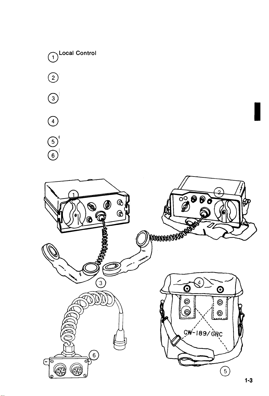
1-8. DESCRIPTION OF MAJOR COMPONENTS
a. Control Group AN/GRA-6
Permits local selection of telephone operation or push-to-talk operation.
TM 11-5820-489-10
TO 31R4-2GRA6-31
Remote Control
Handsets
Bag
Carrying strap
Interconnecting
Box
Permits field telephone operation connec-
tions with local control up to a 2 mile range
Used for transmitting and receiving voice
signals.
Used to contain Control Units, Handset, and
running spare parts when not in use.
For use in carrying Remote Control Unit.
Used when Handset and Loudspeaker are
needed at the same time.
1-3
TM 11-5820-489-10
TO 31R4-2GRA6-31
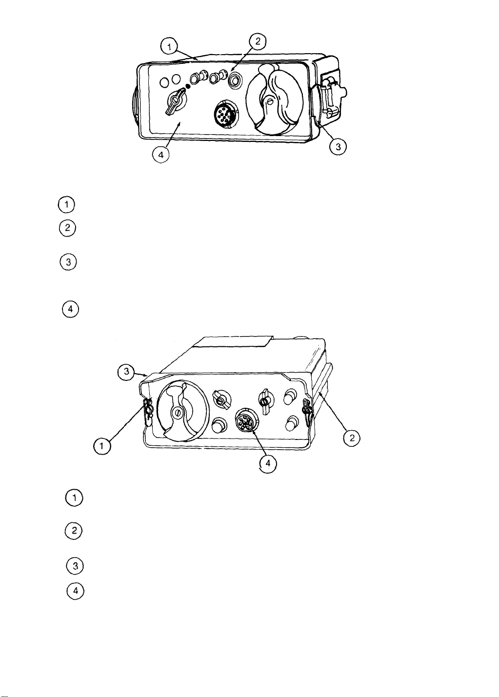
b. Remote Control
Outer Case
Battery Compartment
Cover (under case)
“D” rings
Front Panel
c. Local Control
Waterproof, houses panel and chassis.
Provides access to area that contains bat-
teries.
These hold shoulder strap for carrying posi-
tion. In carrying position, operating controls
of front panel face upward.
Contains controls and instruments for opera-
tion.
1-4
Front Panel
Channel or Mounting
runners
Outer Case
Connector
Contains controls and instruments for operation.
Allows Local Control to be mounted for plugin connection to radio sets using mounting.
Waterproof, houses panel and chassis.
Plugs into a mating connector on a mounting
radio set to establish an electrical connection between Control Unit and radio set (see
rear view).

TM 11-5820-489-10
TO 31R4-2GRA6-31
Cable Compartment
5
o
o
o
o
o
o
Cover Latch
Cable Assembly
6
Cable Compartment
7
Cover
Cap Retainer Chain
8
Cap
9
Cap Retaining
10
Bracket
d. Handset
A means to control opening and
closing of cable compartment cover.
Means for establishing electrical connections
between Control Unit and radio sets.
Provides access to area that contains cable
assembly.
An aid to preventing loss of cap.
Used for the protection of connector plug
when not in use.
Used to hold the cap when the connector is
being used.
Push-to-talk switch
is used to provide
voice communication.
Push switch to talk
and release switch
to listen.
e. Interconnecting box
Plug Connector
Receptacle Connectors
When plugged into Remote Control, provides
extra electrical power to extension.
Needed when Loudspeaker and Handset are
used at the same time.
1-5

TM 11-5820-489-10
TO 31R4-2GRA6-31
1-9. DIFFERENCES BETWEEN MODELS
Generators
G-25/PT (used in this manual)
rotates at 155 rpm.
1-10. PERFORMANCE DATA
ITEMS USED IN AN OPERABLE CONTROL GROUP
Item
No.
Qty.
1 1
Component Requirements
Remote Control
C-433/GRC
2
Local Control
1
C-434/GRC
3
Handset H-33/PT
2
Power
80 to 100v ac, 20 Hz
single ph battery 3v
+ 45v dc.
80 to 100v ac, 20 Hz
single ph dc battery
power, 3v.
300 ohms impedance,
100 Hz, carbon type
xmtr 40 ohms dc
resistance, 60 ma 300 to
4000 Hz freq. range.
G-25A/PT (others)
rotates at 208 rpm
Technical
Characteristics
manual control,
alumn, 7lbs, (3.15
kg) 9-3/8” I X :
3½” h X 7“ w
manual control,
alumn, 10½ lbs.,
(5.6 kg) 8-9/16” I
X 10½" w X 3½” h
battery powered,
black plastic
handle, magnetic
receiver 1-1/81bs.
(.51 kg)
4
5
6
7 4
8
1-6
1
Interconnecting
Box J-654/G
Container for
1
Interconnecting
B
OX
J-654/G
1
Loudspeaker,
Dynamic LS-166/U
Battery, dry BA-30
1
Battery, dry
BA-414/U
8 ohms voice call
impedance, 2W normal
and 3W peak input
1.5V
45v tapped at 22v
3/8” dia. cable
accom, alumn
w/cover, 1 lb. (.45
kg ) 4-5/8” lg X
2-1/8” w X 1¼” h
(incl. 3 ft. interconnection cord)
2lbs. (.9 kg) X 0.2
cu ft.
5-21/32 “ l X
3-3/16” w X 7-1/32 "
h
(2 ea. local control)
(2 ea. remote
control)
used with remote
control

TM 11-5820-489-10
TO 31R4-2GRA6-31
ITEMS USED IN AN OPERABLE CONTROL GROUP - Continued
Item
No.
10
Qty. Component
9
1
Lamp, glow
1
Lamp, glow
Dry batteries shown are used with the equipment, but
are not considered part of the equipment. They will not
be preshipped automatically, but are to be requisitioned in quantities necessary for the particular organization in accordance with SB 11-6.
Power
Requirements
1/25w, 65v, ac, 90v dc
1/25w, 65v, ac, 90v dc
NOTE
Technical
Characteristics
neon gas, GE type
NE51 (used with
local control) 1-1/8”
h o/a
neon gas GE NE-51
(used with remote
control) 1-1/8”h o/a
1-7

Section Ill.
1-11.
ARRANGEMENT OF LOCAL CONTROL TO REMOTE CONTROL
Up to 2 miles of Ii
TECHNICAL PRINCIPLES OF OPERATION
1-8
Remote Control


TM 11-5820-489-10
TO 31R4-2GRA6-31
CHAPTER 2
OPERATING INSTRUCTIONS
Controls and lndicators . . . . . . . . . . . . . . . . . . . . . . . . . . . . . . . . . . . . . . . . .
Local Unit . . . . . . . . . . . . . . . . . . . . . . . . . . . . . . . . . . . . . . . . . . . . . . . . . .
Remote Unit . . . . . . . . . . . . . . . . . . . . . . . . . . . . . . . . . . . . . . . . . . . . . . . .
Initial adjustment . . . . . . . . . . . . . . . . . . . . . . . . . . . . . . . . . . . . . . . . . . . . . .
Telephone circuits . . . . . . . . . . . . . . . . . . . . . . . . . . . . . . . . . . . . . . . . . . .
Telephone lines . . . . . . . . . . . . . . . . . . . . . . . . . . . . . . . . . . . . . . . . . . . . .
Write-in blanks . . . . . . . . . . . . . . . . . . . . . . . . . . . . . . . . . . . . . . . . . . . . . .
Assembly and Preparation for Use . . . . . . . . . . . . . . . . . . . . . . . . . . . . . . . . . . . .
Accessories . . . . . . . . . . . . . . . . . . . . . . . . . . . . . . . . . . . . . . . . . . . . . . . .
Local Control Unit . . . . . . . . . . . . . . . . . . . . . . . . . . . . . . . . . . . . . . . . . . .
Remote Control Unit . . . . . . . . . . . . . . . . . . . . . . . . . . . . . . . . . . . . . . . . .
Operating Procedure . . . . . . . . . . . . . . . . . . . . . . . . . . . . . . . . . . . . . . . . . . .
Break-in . . . . . . . . . . . . . . . . . . . . . . . . . . . . . . . . . . . . . . . . . . . . . . . . . . . .
Local push-to-talk . . . . . . . . . . . . . . . . . . . . . . . . . . . . . . . . . . . . . . . . . . . .
Monitoring . . . . . . . . . . . . . . . . . . . . . . . . . . . . . . . . . . . . . . . . . . . . . . . . . .
Remote push-to-talk . . . . . . . . . . . . . . . . . . . . . . . . . . . . . . . . . . . . . . . . . .
Ringing . . . . . . . . . . . . . . . . . . . . . . . . . . . . . . . . . . . . . . . . . . . . . . . . . . . .
Stopping . . . . . . . . . . . . . . . . . . . . . . . . . . . . . . . . . . . . . . . . . . . . . . . . . . .
Operation - Unusual conditions. . . . . . . . . . . . . . . . . . . . . . . . . . . . . . . . . .
Arctic Climates . . . . . . . . . . . . . . . . . . . . . . . . . . . . . . . . . . . . . . . . . . . . . .
Desert Climates . . . . . . . . . . . . . . . . . . . . . . . . . . . . . . . . . . . . . . . . . . . . .
Tropical Climates . . . . . . . . . . . . . . . . . . . . . . . . . . . . . . . . . . . . . . . . . . . .
Preventive Maintenance . . . . . . . . . . . . . . . . . . . . . . . . . . . . . . . . . . . . . . . .
2-1
2-1
2-5
2-24
2-24
2-23
2-25
2-13
2-23
2-17
2-13
2-27
2-34
2-33
2-33
2-31
2-28
2-37
2-38
2-38
2-38
2-38
2-8
(1-9 blank)/2-0

TM 11-5820-489-10
TO 31R4-2GRA6-31
Section I. DESCRIPTION AND USE OF OPERATOR’S CONTROLS AND
INDICATORS
2-1. PANEL CONTROLS AND FACILITIES
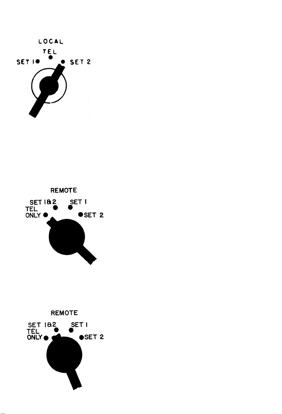
a. Local Control Panel controls and indicators.
Local Switch
POSITION
of Control or
Indicators
FUNCTION
when used with Local
Control Unit
● Allows push-to-talk operation of
Set 1 (using spring action).
● Allows Telephone operation with
Remote Control.
2-1
TM 11-5820-489-10
TO 31R4-2GRA6-31
POSITION
Remote Switch
FUNCTION
● Allows push-to-talk operation of
Set 2 (using spring action).
● Allows Telephone communication
between Local and Remote Control
Units.
● May also be used to turn power
OFF in TEL ONLY position.
● For push-to-talk operation of either
Set 1 or Set 2 move REMOTE knob
to Set 1 and Set 2 setting. Local
Control is now ON.
2-2

TM 11-5820-489-10
TO 31R4-2GRA6-31
POSITION
FUNCTION
● Provides for Remote Control of
power for a radio set and pushto-talk operation of Set 1.
● Monitors Set 1 and Set 2.
● Provides for Remote Control of
power for a radio set and push-to-
talk operation of Set 2.
Wire Binding Posts
● Monitors Set 1 and Set 2.
● Allows connection of lines for
remote control.
2-3

TM 11-5820-489-10
TO 31R4-2GRA6-31
To prevent accidental operation of the radio set
transmitters, the REMOTE switch of Local Control
MUST be in the TEL ONLY position when ringing
generator is operated.
Ringing Generator
NOTE
POSITION
Call Light
FUNCTION
handle and turning
vides the means of
ycle ringing signal
Control Unit.
●
When lit, shows that a ringing signal
is being received from the Remote Control
Unit.
● Using dimmer, call light can be adjusted
to desired brightness.
●
Turn clockwise to dim,
counterclockwise to brighten.
Audio Connector
2-4
●
Connection point for a Handset or similar
accessory for telephone communication
and push-to-talk operation of the radio
set.
NOTE
Use audio cover when
not in operation.

b. Remote Control Panel controls and indicators.
Selector Switch
TM 11-5820-489-10
TO 31R4-2GRA6-31
POSITION
of Control or
Indicators
FUNCTION
when used with Local Control
Unit
● Provides power ON position for a
radio set and/or Set 1 or Set 2
depending on indicator setting at
Local Control Unit.
Write-in positions (spaces) for operator
to record functions of switch positions.
●
Provides power OFF position for
a radio set and/or Set 1 or Set 2
depending on indicator setting at
Local Control Unit.
NOTE
The functions of the write-in positions will be reversed if the telephone line
connections are reversed at either Local or Control units.
2-5

TM 11-5820-489-10
TO 31R4-2GRA6-31
POSITION
of Control or
Indicator
Wire Bind Posts
FUNCTION
when used with Local Control
Unit
● For telephone communications with
Local Control Unit.
● Allows connection of Remote
Control Unit.
NOTE
To prevent accidental operation of the radio set
transmitters, the REMOTE switch of Local Control
MUST be in the TEL ONLY position when ringing
generator is operated.
Ringing Generator
●
Using spinner handle and turning
clockwise provides the means of
sending a 20-cycle ringing signal
to the Local Control Unit.
Fold-out handle
2-6

TM 11-5820-489-10
TO 31R4-2GRA6-31
POSITION
of Control or
Indicator
Call Light
Audio Connector
FUNCTION
when used with Local Control
Unit
When lit, shows that a ringing
signal is being received at the
Local Control Unit.
Using dimmer, call light can be
adjusted to desired brightness.
●
Turn clockwise to dim,
counterclockwise to brighten.
● This is where a Handset or similar
accessory for telephone communication and push-to-talk operation of the
radio set is connected.
● Use audio cover when
not in operation.
2-7

TM 11-5820-489-10
TO 31R4-2GRA6-31
Section Il. PREVENTIVE MAINTENANCE CHECKS AND SERVICES (PMCS)
2-2. GENERAL
Operator’s Preventive Maintenance Checks and Services (PMCS) are the required daily and weekly inspections and care of your equipment necessary to
keep it in good operating condition.
Tools and Materials
No tools or equipment are required for operator maintenance. The following
cleaning materials will be useful to you:
● Lint-free cloths
● Soft bristle brush
● Dishwashing compound or detergent
● Cleaning compound
2-3. PREVENTIVE MAINTENANCE CHECKS AND SERVICES PROCEDURES
NOTE
If your Control Group AN/GRA-6 must be in USE ALL
THE TIME, check and service those items that can be
checked and serviced without stopping its operation.
Make COMPLETE checks and services ONLY when the
Control Group is finally SHUT DOWN.
2-8

TM 11-5820-489-10
TO 31R4-2GRA6-31
a. Routine Services
Routine services are not listed in the PMCS table. They are, however,
important and should be done on a routine basis. Here are the routine
steps to be performed by you as necessary:
●
● Clean
● Dust
● Wash
● Check for cut or frayed
cables
● Check for dented, bent, or
broken components
Check to see that items not
in use are properly stored
●
Check for rusting
●
Check controls for smooth
operation
●
Cover unused receptacles
●
Check for loose nuts, bolts,
and connectors
●
Check for completeness and
current changes to publications
b. Explanation of INTERVAL column of PMCS chart
NOTE
Always keep in mind all CAUTIONS and WARNINGS
when PMCS are performed.
WEEKLY - Do your Weekly (W) PMCS to ensure that the
Control Group is functioning properly.
2-9

TM 11-5820-489-10
TO 31R4-2GRA6-31
NOTE
ALL PMCS must be done as regularly scheduled and
also under the following conditions:
● Before the Control Group is used on a mission.
● When the Control Group is first installed.
●
When the Control Group is reinstalled after being
removed for any reason.
●
When you are operating the Control Group for the
first time.
c. Explanation of EQUIPMENT IS NOT READY/AVAILABLE IF
column of PMCS chart.
l This column tells the conditions under which the equipment can not
perform the assigned mission requirements.
NOTE
The procedures column in your PMCS chart tells you
how to perform the required checks and services.
Carefully follow these instructions. If tools are needed
or the chart instructions tell you, get organizational
maintenance to do the necessary work.
NOTE
If any portion of your Control Group fails to operate, refer to Chapter 3
under Troubleshooting for possible corrective action. Report any
malfunctions or failures on the proper DA Form 2404 or refer to TM
38-750.
2-10
 Loading...