

Military surplus Use_and_care_of_hand_tools_and_measuring_tools_TM9-243_2022.pdf Use_and_care_of_hand_tools_and_measuring_tools_TM9-243_2022.pdf
AIR FORCE AIR FORCE TO 32-1-101
BASIC AND ALL UPDATES HAVE BEEN MERGED TO MAKE THIS A COMPLETE PUBLICATION.
ARMY ARMY TM 9-243
NAVY (NAVAIR) NAVY M6290-AJ-MAN-1010
MARINE CORPS MARINE CORP TM
10209-10/1
TECHNICAL MANUAL
USE AND CARE OF HAND TOOLS AND MEASURING
TOOLS
DISTRIBUTION STATEMENT A - Approved for public release; distribution is unlimited. PA Case Number 05-07153. Other requests for this
document shall be referred to 406 SCMS/GUEE, Robins AFB, GA 31098. Questions concerning technical content shall be referred to
AFLCMC/EZPT.
Published UnderAuthority of the Secretary of the Air Force
19 AUGUST 2020 CHANGE 2 - 8 APRIL 2022

AIR FORCE AIR FORCE TO 32-1-101
ARMY ARMY TM 9-243
MARINE CORPS MARINE CORP TM 10209-10/1
NAVY (NAVAIR) NAVY M6290-AJ-MAN-1010
LIST OF EFFECTIVE PAGES
Dates of issue for original and changed pages are:
NOTE
Original........0.....19August 2020
Change ........1.....5October 2020
TOTAL NUMBER OF PAGES IN THIS PUBLICATION IS 518, CONSISTING OF THE FOLLOWING:
Page *Change
No. No.
Page *Change
No. No.
INSERT LATEST CHANGED PAGES. DESTROY SUPERSEDED PAGES.
The portion of the text affected by the changes is indicated by a vertical line in the outer margins of
the page. Changes to illustrations are indicated by shaded or screened areas, or by miniature
pointing hands.
Change ........2.......8April 2022
Page *Change
No. No.
Title......................2
A........................2
i - xvii....................0
xviii Blank..................0
xix-xx...................0
xxi.......................2
xxii - xxiii .................0
xxiv Blank..................0
1-1.......................0
1-2 Blank ..................0
2-1.......................0
2-2.......................1
2-3.......................0
2-4.......................2
2-5-2-6...................0
3-1-3-3...................0
3-4 Blank ..................0
4-1-4-2...................0
5-1-5-3...................0
5-4 Blank ..................0
6-1-6-8...................0
7-1-7-7...................0
7-8 Blank ..................0
8-1-8-5...................0
8-6 Blank ..................0
9-1-9-4...................0
10-1 - 10-4.................0
11-1-11-9.................0
11-10 Blank.................0
12-1 - 12-4.................0
13-1 - 13-13 ................0
13-14 Blank.................0
14-1 - 14-5.................0
14-6 Blank..................0
15-1 - 15-15 ................0
15-16 Blank.................0
16-1 - 16-13 ................0
16-14 Blank.................0
17-1 ......................2
17-2 - 17-3.................0
17-4 - 17-5.................1
17-6 - 17-10 ................0
18-1 - 18-7.................0
18-8 ......................2
19-1 - 19-5.................0
19-6 Blank..................0
20-1 - 20-9.................0
20-10 Blank.................0
21-1 - 21-26 ................0
22-1 - 22-12 ................0
23-1 - 23-7.................0
23-8 Blank..................0
24-1 - 24-3.................0
24-4 ......................1
24-5 Added .................1
24-6 Blank..................1
25-1 - 25-12 ................0
25-13 .....................1
25-14 - 25-27 ...............0
25-28 Blank.................0
26-1 - 26-9.................0
26-10 Blank.................0
27-1 - 27-11................0
27-12 Blank.................0
28-1 - 28-9.................0
28-10 Blank.................0
29-1 - 29-11................0
29-12 Blank
.................0
30-1 - 30-4.................0
31-1 - 31-3.................0
31-4 Blank..................0
32-1 - 32-6.................0
33-1 - 33-6.................0
34-1 - 34-6.................0
35-1 - 35-13 ................0
35-14 Blank.................0
36-1 - 36-6.................0
37-1 - 37-6.................0
38-1 - 38-12 ................0
39-1 - 39-6.................0
40-1 - 40-6.................0
41-1 - 41-8.................0
42-1 - 42-4.................0
43-1 - 43-3.................0
43-4 Blank..................0
44-1 - 44-4.................0
45-1 - 45-10 ................0
46-1 - 46-11................0
46-12 Blank.................0
47-1 - 47-4.................0
* Zero in this column indicates an original page.
48-1 - 48-3.................0
48-4 Blank..................0
49-1 - 49-8.................0
50-1 - 50-5.................0
50-6 Blank..................0
51-1 - 51-7.................0
51-8 Blank..................0
52-1 - 52-28 ................0
53-1 - 53-6.................0
54-1 - 54-2.................0
55-1 - 55-21 ................0
55-22 Blank.................0
56-1 - 56-2.................0
Index 1 - Index 14............0
A Change 2 USAF

AIR FORCE AIR FORCE TO 32-1-101
MARINE CORPS MARINE CORP TM 10209-10/1
NAVY (NAVAIR) NAVY M6290-AJ-MAN-1010
ARMY ARMY TM 9-243
TABLE OF CONTENTS
Chapter Page
LIST OF ILLUSTRATIONS ..................................................... xvii
LIST OF TABLES ............................................................ xvii
INTRODUCTION ............................................................ xix
SAFETY SUMMARY ......................................................... xxiii
1 INTRODUCTION ........................................................... 1-1
1.1 HOW TO USE THIS MANUAL .......................................... 1-1
2 SAFETY.................................................................. 2-1
SECTION I ................................................................ 2-1
2.1 GENERAL SAFETY RULES ............................................ 2-1
2.2 TOOL HABITS ...................................................... 2-2
2.2.1 Keep Each Tool in its Proper Storage Place ................................... 2-2
2.2.2 Keep Your Tools in Good Condition ........................................ 2-3
2.2.3 Keep Your Tool Set Complete ............................................ 2-3
2.2.4 Use Each Tool Only on the Job for Which it was Designed ........................ 2-3
2.2.5 Keep Your Tools Within Easy Reach and Where They Cannot Fall on the Floor or on
Machinery........................................................ 2-3
2.2.6 Never Use Damaged Tools .............................................. 2-4
SECTION II ............................................................... 2-4
2.3 POWER TOOL SAFETY ............................................... 2-4
SECTION III ............................................................... 2-5
2.4 PERSONAL PROTECTIVE EQUIPMENT (PPE) ............................... 2-5
2.4.1 SAFETY SHOES ..................................................... 2-5
2.4.2 EYE PROTECTION................................................... 2-5
2.4.3 HELMETS ......................................................... 2-6
2.4.4 GLOVES .......................................................... 2-6
2.4.5 SAFETY BELTS AND SAFETY STRAPS.................................... 2-6
2.4.6 HEARING PROTECTION .............................................. 2-6
3 READING MEASURING SCALES ............................................... 3-1
3.1 READING MEASURING SCALES INTRODUCTION ........................... 3-1
3.2 READING THE SCALE OF A RULE OR TAPE ............................... 3-1
3.3 READING A METRIC RULE ............................................ 3-3
4 TOOL BOXES.............................................................. 4-1
4.1 HOW TO CHOOSE AND USE TOOL BOXES ................................ 4-1
4.2 TOOL BOXES TYPES AND USES ........................................ 4-1
i

AIR FORCE AIR FORCE TO 32-1-101
ARMY ARMY TM 9-243
MARINE CORPS MARINE CORP TM 10209-10/1
NAVY (NAVAIR) NAVY M6290-AJ-MAN-1010
TABLE OF CONTENTS - CONTINUED
Chapter Page
5 DIVIDERS ................................................................ 5-1
5.1 HOW TO CHOOSE AND USE DIVIDERS ................................... 5-1
5.2 DIVIDERS TYPES AND USES ........................................... 5-1
5.2.1 Spring Divider....................................................... 5-2
5.2.2 Wing Divider........................................................ 5-2
5.3 USING A DIVIDER TO SCRIBE A CIRCLE.................................. 5-3
5.4 CARE OF DIVIDERS ................................................. 5-3
6 CALIPERS ................................................................ 6-1
6.1 HOW TO CHOOSE AND USE CALIPERS ................................... 6-1
6.2 CALIPERS TYPES AND USES........................................... 6-1
6.2.1 Simple Calipers ...................................................... 6-2
6.2.2 Spring-Joint Calipers .................................................. 6-2
6.2.3 Transfer Calipers ..................................................... 6-3
6.2.4 Hermaphrodite Calipers................................................. 6-3
6.2.5 Slide Calipers ....................................................... 6-4
6.2.6 Vernier Calipers ...................................................... 6-5
6.2.7 Trammels .......................................................... 6-6
6.3 READING A VERNIER CALIPER......................................... 6-6
6.4 READING A METRIC CALIPER ......................................... 6-7
6.5 CARE OF CALIPERS ................................................. 6-7
7 MICROMETERS ............................................................ 7-1
7.1 HOW TO CHOOSE AND USE MICROMETERS............................... 7-1
7.2 MICROMETERS TYPES AND USES ...................................... 7-1
7.2.1 Outside Micrometers................................................... 7-1
7.2.2 Inside Micrometers.................................................... 7-2
7.2.3 Depth Micrometers.................................................... 7-2
7.3 SELECTING THE PROPER MICROMETER ................................. 7-3
7.4 READING A STANDARD MICROMETER................................... 7-5
7.4.1 To Read a Measurement as Shown in the Paragraph Above: ........................ 7-5
7.5 READING A VERNIER MICROMETER .................................... 7-6
7.5.1 To Read a Measurement as Shown Above:.................................... 7-6
7.6 READING A METRIC MICROMETER ..................................... 7-7
7.6.1 To Read a Measurement as Shown Above .................................... 7-7
7.7 CARE OF MICROMETERS ............................................. 7-7
8 RULES AND STEEL TAPES.................................................... 8-1
8.1 HOW TO CHOOSE AND USE RULES AND STEEL TAPES ...................... 8-1
8.2 RULES AND STEEL TAPES TYPES AND USES .............................. 8-2
8.2.1 Rules ............................................................. 8-2
8.2.2 Folding Rules ....................................................... 8-3
8.2.3 Steel Tapes ......................................................... 8-3
8.3 USING RULERS AND TAPES EXAMPLES .................................. 8-4
8.4 CARE OF RULES AND TAPES .......................................... 8-4
9 MISCELLANEOUS MEASURING TOOLS.......................................... 9-1
ii

AIR FORCE AIR FORCE TO 32-1-101
MARINE CORPS MARINE CORP TM 10209-10/1
NAVY (NAVAIR) NAVY M6290-AJ-MAN-1010
ARMY ARMY TM 9-243
TABLE OF CONTENTS - CONTINUED
Chapter Page
9.1 HOW TO CHOOSE AND USE MISCELLANEOUS MEASURING TOOLS ............ 9-1
9.2 MISCELLANEOUS MEASURING TOOLS TYPES AND USES .................... 9-1
9.2.1 Adjustable Parallel .................................................... 9-1
9.2.2 V-Block and Clamp ................................................... 9-2
9.2.3 Angle Plates ........................................................ 9-2
9.2.4 Magnetic Base Indicator Holder ........................................... 9-3
9.2.5 Registering Speed Indicators ............................................. 9-3
9.3 USING MISCELLANEOUS MEASURING TOOLS ............................. 9-4
9.4 CARE OF MISCELLANEOUS MEASURING TOOLS ........................... 9-4
10 LEVELS .................................................................. 10-1
10.1 HOW TO CHOOSE AND USE LEVELS .................................... 10-1
10.2 LEVELS TYPES AND USES ............................................ 10-1
10.2.1 Master Precision Level ................................................. 10-1
10.2.2 Machinist’s Level..................................................... 10-2
10.2.3 Iron Bench Level ..................................................... 10-2
10.2.4 Striding Level ....................................................... 10-2
10.2.5 Carpenter’s Level ..................................................... 10-2
10.2.6 Line Level ......................................................... 10-3
10.3 USING A LEVEL .................................................... 10-3
10.3.1 Horizontal Surface .................................................... 10-3
10.3.2 Angled Surface ...................................................... 10-4
10.3.3 Vertical Surface ...................................................... 10-4
11 PLUMB BOBS ............................................................. 11-1
11.1 HOW TO CHOOSE AND USE PLUMB BOBS ................................ 11-1
11.2 PLUMB BOBS TYPES AND USES ........................................ 11-1
11.2.1 Plumb Bobs......................................................... 11-1
11.2.2 Surveyor’s Polished Brass ............................................... 11-1
11.2.3 Solid Steel ......................................................... 11-2
11.3 USING A PLUMB BOB ................................................ 11-3
11.4 CARE OF PLUMB BOBS............................................... 11-9
12 SCRIBERS ................................................................ 12-1
12.1 HOW TO CHOOSE AND USE SCRIBERS ................................... 12-1
12.2 SCRIBERS TYPES AND USES........................................... 12-1
12.2.1 Machinist’s Scribers ................................................... 12-1
12.3 USING A MACHINIST’S SCRIBER ....................................... 12-2
12.4 CARE OF SCRIBERS ................................................. 12-3
13 SQUARES ................................................................ 13-1
13.1 HOW TO CHOOSE AND USE SQUARES ................................... 13-1
13.2 SQUARES TYPES AND USES ...........................................
13.2.1 Carpenter’s Square .................................................... 13-2
13.2.2 Try Square ......................................................... 13-4
13.2.3 Combination Square ................................................... 13-4
13.2.4 Sliding T-Bevel ...................................................... 13-5
13.2.5 Bevel Protractor...................................................... 13-5
13-2
iii

AIR FORCE AIR FORCE TO 32-1-101
ARMY ARMY TM 9-243
MARINE CORPS MARINE CORP TM 10209-10/1
NAVY (NAVAIR) NAVY M6290-AJ-MAN-1010
TABLE OF CONTENTS - CONTINUED
Chapter Page
13.3 USING A CARPENTER’S SQUARE TO MARK A SQUARE LINE.................. 13-5
13.4 USING A CARPENTER’S SQUARE TO LAY OUT STEPS ....................... 13-6
13.5 USING A TRY SQUARE ............................................... 13-6
13.6 USING A SLIDING T-BEVEL SQUARE .................................... 13-7
13.7 USING A COMBINATION SQUARE....................................... 13-8
13.7.1 Using as a Center Head to Find the Diameter of a Cylinder ........................ 13-8
13.7.2 Using as a Protractor Head to Determine an Angle .............................. 13-9
13.7.3 Using a Combination Square to Determine Depth ............................... 13-11
13.8 CARE OF SQUARES.................................................. 13-13
14 SURFACE, DEPTH, AND HEIGHT GAGES ......................................... 14-1
14.1 HOW TO CHOOSE AND USE SURFACE, DEPTH, AND HEIGHT GAGES............ 14-1
14.2 SURFACE, DEPTH, AND HEIGHT GAGES TYPES AND USES ................... 14-1
14.2.1 Surface Gage........................................................ 14-1
14.2.2 Rule Depth Gage ..................................................... 14-2
14.2.3 Micrometer Depth Gage ................................................ 14-2
14.2.4 Vernier Depth Gage ................................................... 14-3
14.2.5 Height Gage ........................................................ 14-3
14.2.6 Surface Plate ........................................................ 14-4
14.3 USING THE SURFACE, DEPTH, AND HEIGHT GAGES ........................ 14-4
14.3.1 Using a Surface Gage .................................................. 14-4
14.3.2 Using a Rule Depth Gage ............................................... 14-4
14.3.3 Using a Micrometer Depth Gage .......................................... 14-5
14.3.4 Using a Vernier Depth Gage ............................................. 14-5
14.3.5 Using a Height Gage .................................................. 14-5
14.4 CARE OF SURFACE, HEIGHT, AND DEPTH GAGES .......................... 14-5
15 RING AND SNAP GAGES AND GAGE BLOCKS..................................... 15-1
15.1 HOW TO CHOOSE AND USE RING AND SNAP GAGES AND GAGE BLOCKS ....... 15-1
15.2 RING AND SNAP GAGES AND GAGE BLOCKS TYPES AND USES ............... 15-1
15.2.1 Ring Gages ......................................................... 15-3
15.2.2 Snap Gages......................................................... 15-4
15.2.3 Gage Blocks ........................................................ 15-5
15.3 USING A RING GAGE ................................................ 15-5
15.4 USING AN ADJUSTABLE SNAP GAGE .................................... 15-7
15.5 GAGING FLAT PARTS ................................................ 15-9
15.6 GAGING CYLINDRICAL PARTS ......................................... 15-10
15.7 HOW TO USE PRECISION GAGE BLOCKS ................................. 15-11
15.8 FACTORS TO CONSIDER WHEN USING GAGE BLOCKS ...................... 15-13
15.9 CARE OF RING AND SNAP GAGES ...................................... 15-14
15.10 CARE OF GAGE BLOCKS ............................................. 15-14
16 MISCELLANEOUS MEASURING GAGES.......................................... 16-1
16.1 HOW TO CHOOSE AND USE MISCELLANEOUS MEASURING GAGES ............ 16-1
16.2 MISCELLANEOUS MEASURING GAGES TYPES AND USES .................... 16-2
16.2.1 Thickness (Feeler) Gages................................................ 16-2
16.2.2 Center Gage ........................................................ 16-3
16.2.3 Screw Pitch Gages .................................................... 16-4
16.2.4 Small Hole Gage Set .................................................. 16-4
16.2.5 Telescoping Gages .................................................... 16-5
iv

AIR FORCE AIR FORCE TO 32-1-101
MARINE CORPS MARINE CORP TM 10209-10/1
NAVY (NAVAIR) NAVY M6290-AJ-MAN-1010
ARMY ARMY TM 9-243
TABLE OF CONTENTS - CONTINUED
Chapter Page
16.2.6 Threaded Cutting Tool Gages............................................. 16-5
16.2.7 Fillet and Radius Gages ................................................ 16-6
16.2.8 Drill Point Gage...................................................... 16-6
16.2.9 Wire Gages ......................................................... 16-6
16.2.10 Drill Gages ......................................................... 16-7
16.2.11 Marking Gages ...................................................... 16-7
16.3 USING A THICKNESS GAGE ........................................... 16-8
16.4 USING A CENTER GAGE .............................................. 16-8
16.5 USING A SCREW PITCH GAGE ......................................... 16-8
16.6 USING A SMALL HOLE GAGE .......................................... 16-9
16.7 USING A TELESCOPING GAGE ......................................... 16-9
16.8 USING A THREAD CUTTING TOOL GAGE ................................. 16-10
16.9 USING A FILLET AND RADIUS GAGE .................................... 16-11
16.10 USING A DRILL POINT GAGE .......................................... 16-11
16.11 USING A WIRE GAGE ................................................ 16-12
16.12 USING A DRILL GAGE................................................ 16-12
16.13 USING MARKING GAGES ............................................. 16-13
16.14 CARE OF GAGES.................................................... 16-13
17 PLIERS AND TONGS ........................................................ 17-1
17.1 HOW TO CHOOSE AND USE PLIERS AND TONGS ........................... 17-1
17.2 PLIERS AND TONGS TYPES AND USES ................................... 17-2
17.2.1 Slip-joint Pliers ...................................................... 17-2
17.2.2 Diagonal Cutting Pliers ................................................. 17-2
17.2.3 Lineman’s Side Cutting Pliers ............................................ 17-2
17.2.4 Parallel Jaw Pliers .................................................... 17-3
17.2.5 Flat-nose Pliers ...................................................... 17-3
17.2.6 Round-nose Pliers .................................................... 17-3
17.2.7 Straight-lip Flat-jaw Tongs............................................... 17-3
17.2.8 End Cutting Pliers .................................................... 17-4
17.2.9 Wire Strippers (Multipurpose) ............................................ 17-4
17.2.10 Crimping Tools ...................................................... 17-4
17.2.11 Wire Twister ........................................................ 17-5
17.3 USING SLIP-JOINT PLIERS ............................................ 17-5
17.4 USING DIAGONAL CUTTING PLIERS .................................... 17-7
17.5 USING LINEMAN’S SIDE CUTTING PLIERS ................................ 17-8
17.6 CARE OF PLIERS AND TONGS ......................................... 17-10
18 VISES ................................................................... 18-1
18.1 HOW TO CHOOSE AND USE VISES ...................................... 18-1
18.2 VISES TYPES AND USES .............................................. 18-1
18.2.1 Machinist’s Bench Vise................................................. 18-1
18.2.2 Bench and Pipe Vise................................................... 18-2
18.2.3 Clamp Base Bench Vise ................................................ 18-2
18.2.4 Pipe Vise .......................................................... 18-3
18.2.5 Machine Table Vise ................................................... 18-3
18.2.6 Pin Vise ........................................................... 18-3
18.2.7 Piston Holding Vise ................................................... 18-4
18.2.8 Handsaw Filing Vise................................................... 18-4
18.3 USING A MACHINIST’S BENCH VISE .................................... 18-5
18.4 USING A PIPE VISE .................................................. 18-7
v

AIR FORCE AIR FORCE TO 32-1-101
ARMY ARMY TM 9-243
MARINE CORPS MARINE CORP TM 10209-10/1
NAVY (NAVAIR) NAVY M6290-AJ-MAN-1010
TABLE OF CONTENTS - CONTINUED
Chapter Page
18.5 CARE OF VISES..................................................... 18-8
19 CLAMPS ................................................................. 19-1
19.1 HOW TO CHOOSE AND USE CLAMPS .................................... 19-1
19.2 CLAMPS TYPES AND USES ............................................ 19-1
19.2.1 C-Clamps .......................................................... 19-1
19.2.2 Hand Screw Clamps ................................................... 19-2
19.3 USING A C-CLAMP .................................................. 19-2
19.4 USING A HAND SCREW CLAMP ........................................ 19-4
19.5 CARE OF C-CLAMPS................................................. 19-5
19.6 CARE OF HAND SCREW CLAMPS ....................................... 19-5
20 JACKS ................................................................... 20-1
20.1 HOW TO CHOOSE AND USE JACKS...................................... 20-1
20.2 JACK TYPES AND USES .............................................. 20-1
20.2.1 Screw Jacks......................................................... 20-1
20.2.2 Ratchet Lever Jacks ................................................... 20-2
20.2.3 Hydraulic Jacks ...................................................... 20-3
20.3 SAFETY........................................................... 20-4
20.4 USING A BELL BASE SCREW JACK...................................... 20-5
20.5 USING A RATCHET LEVER JACK ....................................... 20-7
20.6 CARE OF JACKS .................................................... 20-9
21 HAMMERS, MALLETS AND MAULS ............................................ 21-1
21.1 HOW TO CHOOSE AND USE HAMMERS, MALLETS AND MAULS ............... 21-1
21.2 HAMMERS, MALLETS AND MAULS TYPES AND USES ....................... 21-2
21.2.1 Carpenter’s Hammer ................................................... 21-2
21.2.2 Machinist’s Peen Hammer ............................................... 21-3
21.2.3 Bumping Body Hammer ................................................ 21-3
21.2.4 Blacksmith’s or Sledge Hammers .......................................... 21-4
21.2.5 Jeweler’s Hammer .................................................... 21-5
21.2.6 Mason’s Hammer ..................................................... 21-5
21.2.7 Napping Hammer..................................................... 21-5
21.2.8 Riveting Hammer..................................................... 21-5
21.2.9 Sawmaker’s Hammer .................................................. 21-6
21.2.10 Setting Hammer...................................................... 21-6
21.2.11 Soft-Faced Hammer ................................................... 21-6
21.2.12 Lead or Copper Hammer................................................ 21-7
21.2.13 Inserted Soft-Faced Hammer ............................................. 21-7
21.2.14 Trimmer’s Hammer ................................................... 21-8
21.2.15 Welder’s Hammer..................................................... 21-8
21.2.16 Dead Blow Hammers .................................................. 21-9
21.2.17 Mallets ............................................................ 21-9
21.2.18 Mauls............................................................. 21-10
21.3 HAMMERS, MALLETS AND MAULS SAFETY .............................. 21-11
21.3.1 Specific Steps to Take.................................................. 21-12
21.4 USING HAMMERS ................................................... 21-13
21.4.1 Using a Carpenter’s Hammer ............................................. 21-14
21.4.2 Using a Mechinist’s Ball Peen Hammer ...................................... 21-18
21.5 CARE OF HAMMERS................................................. 21-19
vi

AIR FORCE AIR FORCE TO 32-1-101
MARINE CORPS MARINE CORP TM 10209-10/1
NAVY (NAVAIR) NAVY M6290-AJ-MAN-1010
ARMY ARMY TM 9-243
TABLE OF CONTENTS - CONTINUED
Chapter Page
21.5.1 Care of Inserted Face Hammers ........................................... 21-20
21.6 REPLACING THE HANDLE ............................................ 21-21
21.6.1 Removing Old Hammer Handle ........................................... 21-21
21.6.2 Installation of New Handle .............................................. 21-23
22 SCREWDRIVERS ........................................................... 22-1
22.1 HOW TO CHOOSE AND USE SCREWDRIVERS .............................. 22-1
22.2 SCREWDRIVERS TYPES AND USES...................................... 22-1
22.2.1 Common Screwdrivers ................................................. 22-1
22.2.2 Cross-Tip Screwdrivers ................................................. 22-3
22.2.3 Cross-Point Screwdrivers................................................ 22-3
22.2.4 Clutch Head Screwdrivers ............................................... 22-4
22.2.5 Offset Screwdrivers ................................................... 22-4
22.2.6 Ratchet Screwdrivers .................................................. 22-5
22.2.7 Screwdriver Bits ..................................................... 22-5
22.2.8 Jeweler’s Screwdriver .................................................. 22-6
22.2.9 Flexible Screwdrivers .................................................. 22-6
22.2.10 Radio and Pocket Screwdrivers ........................................... 22-6
22.2.11 Screw Starter or Gimlet................................................. 22-7
22.3 SCREWDRIVERS SAFETY ............................................. 22-7
22.4 USING SCREWDRIVERS .............................................. 22-7
22.4.1 Preparing the Work Surface .............................................. 22-8
22.4.2 Using a Screwdriver ................................................... 22-8
22.4.3 Using an Offset Screwdriver ............................................. 22-9
22.4.4 Using an Offset Ratchet Screwdriver ........................................ 22-9
22.4.5 Using a Spiral Ratchet Screwdriver......................................... 22-10
22.4.6 Using a Jeweler’s Screwdriver ............................................ 22-11
22.5 CARE OF SCREWDRIVERS ............................................ 22-11
23 MANUAL DRILLS .......................................................... 23-1
23.1 HOW TO CHOOSE AND USE MANUAL DRILLS ............................. 23-1
23.2 MANUAL DRILLS TYPE AND USES ...................................... 23-2
23.2.1 Brace Drill ......................................................... 23-2
23.2.2 Breast Drill ......................................................... 23-2
23.2.3 Hand Drill.......................................................... 23-3
23.3 USING A BRACE DRILL............................................... 23-3
23.4 USING AN EXPANSIVE BIT ............................................ 23-5
23.5 CARE OF MANUAL DRILLS............................................ 23-7
24 SCREW AND TAP EXTRACTORS ............................................... 24-1
24.1 HOW TO CHOOSE AND USE CREW AND TAP EXTRACTORS ................... 24-1
24.2 SCREW AND TAP EXTRACTORS TYPES AND USES .......................... 24-2
24.2.1 Screw Extractors ..................................................... 24-2
24.2.2 Tap Extractor........................................................ 24-2
24.3 USING A SPIRAL TAPERED SCREW EXTRACTOR ........................... 24-3
24.4 CARE OF EXTRACTORS .............................................. 24-4
25 WRENCHES ............................................................... 25-1
vii

AIR FORCE AIR FORCE TO 32-1-101
ARMY ARMY TM 9-243
MARINE CORPS MARINE CORP TM 10209-10/1
NAVY (NAVAIR) NAVY M6290-AJ-MAN-1010
TABLE OF CONTENTS - CONTINUED
Chapter Page
25.1 HOW TO CHOOSE AND USE WRENCHES ................................. 25-1
25.2 WRENCHES TYPES AND USES ......................................... 25-1
25.2.1 Open-End Wrenches ................................................... 25-1
25.2.2 Box Wrenches ....................................................... 25-3
25.2.3 Combination Wrenches ................................................. 25-5
25.2.4 Socket Wrenches ..................................................... 25-6
25.2.5 Socket Wrench Handles, Extensions and Adapters ............................... 25-7
25.2.6 Special Purpose Socket Wrenches.......................................... 25-9
25.2.7 Crowfoot Wrench..................................................... 25-11
25.2.8 Hexagon Key Wrench (Shorter Section)...................................... 25-11
25.2.9 Plug Wrenches....................................................... 25-11
25.2.10 Adjustable Open-End Wrench ............................................ 25-12
25.2.11 Clamp Pliers ........................................................ 25-13
25.2.12 Monkey and Auto Wrenches ............................................. 25-14
25.2.13 Pipe Wrenches....................................................... 25-14
25.2.14 Torque Wrenches ..................................................... 25-15
25.2.15 Power Torque Wrench.................................................. 25-16
25.2.16 Spanner Wrenches .................................................... 25-17
25.3 WRENCH SAFETY ................................................... 25-18
25.4 HOW TO USE A BOX WRENCH ......................................... 25-18
25.5 USING A SOCKET WRENCH ........................................... 25-19
25.6 USING AN ADJUSTABLE OPEN-END WRENCH ............................. 25-20
25.7 USING AN ADJUSTABLE STRAP PIPE WRENCH............................. 25-21
25.8 USING THE TORQUE WRENCH ......................................... 25-22
25.9 USING THE POWER TORQUE WRENCH................................... 25-23
25.10 USING A SPANNER WRENCH .......................................... 25-27
25.11 CARE ............................................................ 25-27
26 CHISELS ................................................................. 26-1
26.1 HOW TO CHOOSE AND USE CHISELS .................................... 26-1
26.2 CHISELS TYPES AND USES............................................ 26-1
26.2.1 Woodworker’s Chisels.................................................. 26-1
26.2.2 Machinist’s Chisels.................................................... 26-2
26.2.3 Track Chisel ........................................................ 26-2
26.2.4 Rivet Buster Chisel.................................................... 26-2
26.3 USING A WOODWORKER’S CHISEL ..................................... 26-3
26.4 USING A MACHINIST’S COLD CHISEL ................................... 26-5
26.5 USING A RIVET BUSTER CHISEL ....................................... 26-8
26.6 CARE OF CHISELS .................................................. 26-9
27 PUNCHES ................................................................ 27-1
27.1 HOW TO CHOOSE AND USE PUNCHES ................................... 27-1
27.2 PUNCHES TYPES AND USES ........................................... 27-1
27.2.1 Center Punches ...................................................... 27-1
27.2.2 Drift Punch ......................................................... 27-2
27.2.3 Alignment Punch ..................................................... 27-2
27.2.4 Drive Pin Punch...................................................... 27-2
27.2.5 Prick Punch......................................................... 27-2
27.2.6 Starting Punch ....................................................... 27-3
27.2.7 Grommet-Inserting Punch ............................................... 27-3
27.2.8 Catapunch.......................................................... 27-3
viii

AIR FORCE AIR FORCE TO 32-1-101
MARINE CORPS MARINE CORP TM 10209-10/1
NAVY (NAVAIR) NAVY M6290-AJ-MAN-1010
ARMY ARMY TM 9-243
TABLE OF CONTENTS - CONTINUED
Chapter Page
27.2.9 Metal Cutting Punch................................................... 27-3
27.2.10 Tinmen’s Hollow Punch ................................................ 27-4
27.2.11 Sheet Metal Punch .................................................... 27-4
27.2.12 Lever Punch ........................................................ 27-4
27.2.13 Screw Punch ........................................................ 27-4
27.3 USING A CENTER PUNCH ............................................. 27-5
27.4 USING A DRIFT PUNCH............................................... 27-7
27.5 USING AN ALIGNMENT PUNCH ........................................ 27-9
27.6 CARE OF PUNCHES.................................................. 27-11
27.7 SCREW PUNCH USAGE ............................................... 27-11
28 FILES.................................................................... 28-1
28.1 HOW TO CHOOSE AND USE FILES ...................................... 28-1
28.2 FILES TYPES AND USES .............................................. 28-1
28.2.1 American Pattern File .................................................. 28-2
28.2.2 Mill File ........................................................... 28-2
28.2.3 Pillar File .......................................................... 28-2
28.2.4 Round File ......................................................... 28-2
28.2.5 Square File ......................................................... 28-2
28.2.6 Taper File .......................................................... 28-3
28.2.7 Three-Square File..................................................... 28-3
28.2.8 Warding File ........................................................ 28-3
28.2.9 Curved-Tooth File .................................................... 28-3
28.2.10 Swiss Pattern File..................................................... 28-4
28.3 FILE SAFETY ...................................................... 28-4
28.4 USING A FILE ...................................................... 28-4
28.4.1 Selecting Proper File .................................................. 28-4
28.4.2 Method of Filing ..................................................... 28-5
28.4.3 Draw Filing......................................................... 28-5
28.5 CARE OF FILES..................................................... 28-6
28.6 REPLACING THE HANDLE ............................................ 28-8
29 GRINDERS AND SHARPENING STONES.......................................... 29-1
29.1 HOW TO CHOOSE AND USE GRINDERS AND SHARPENING STONES ............ 29-1
29.2 GRINDERS AND SHARPENING STONES TYPES AND USES .................... 29-1
29.2.1 Bench Grinder ....................................................... 29-2
29.2.2 Valve Grinder ....................................................... 29-3
29.2.3 Sharpening Stones .................................................... 29-4
29.3 USING A BENCH GRINDER ............................................ 29-4
29.4 USING A SHARPENING STONE ......................................... 29-8
29.5 CARE OF BENCH GRINDERS........................................... 29-10
29.6 CARE OF SHARPENING STONES ........................................ 29-11
30 SCRAPERS................................................................ 30-1
30.1 HOW TO CHOOSE AND USE SCRAPERS .................................. 30-1
30.2 SCRAPERS TYPES AND USES .......................................... 30-1
30.2.1 Carbon Scraper ...................................................... 30-1
30.2.2 Bearing Scraper ...................................................... 30-2
30.2.3 Box Scraper ........................................................ 30-2
30.2.4 Flat Blade Scraper .................................................... 30-2
ix

AIR FORCE AIR FORCE TO 32-1-101
ARMY ARMY TM 9-243
MARINE CORPS MARINE CORP TM 10209-10/1
NAVY (NAVAIR) NAVY M6290-AJ-MAN-1010
TABLE OF CONTENTS - CONTINUED
Chapter Page
30.2.5 Triangular Blade Scraper ................................................ 30-2
30.3 SCRAPER SAFETY................................................... 30-2
30.4 USING A BEARING SCRAPER .......................................... 30-3
30.5 CARE OF SCRAPERS................................................. 30-4
31 AWLS................................................................... 31-1
31.1 HOW TO CHOOSE AND USE AWLS ...................................... 31-1
31.2 AWLS TYPES AND USES .............................................. 31-1
31.2.1 Saddler’s Awl ....................................................... 31-1
31.2.2 Scratch Awl......................................................... 31-1
31.3 USING A SCRATCH AWL .............................................. 31-2
31.4 CARE OF AWLS..................................................... 31-3
32 BOLT AND CABLE CUTTERS .................................................. 32-1
32.1 HOW TO CHOOSE AND USE BOLT AND CABLE CUTTERS .................... 32-1
32.2 BOLT AND CABLE CUTTERS TYPE AND USES ............................. 32-1
32.2.1 Center Cut Cutter..................................................... 32-2
32.2.2 Clipper Cut Cutter .................................................... 32-2
32.2.3 Shear Cut, Flat Bar, and Strip Cutter........................................ 32-3
32.2.4 Side Nut Splitter Cutter................................................. 32-3
32.2.5 Angular Cut Cutter.................................................... 32-4
32.2.6 Shear Cut Cable Cutter ................................................. 32-4
32.3 CUTTER SAFETY.................................................... 32-4
32.4 USING CENTER CUT CUTTERS ......................................... 32-5
32.5 CARE OF BOLT AND CABLE CUTTERS ................................... 32-6
33 GLASS CUTTERS ........................................................... 33-1
33.1 HOW TO CHOOSE AND USE GLASS CUTTERS ............................. 33-1
33.2 GLASS CUTTERS TYPES AND USES ..................................... 33-1
33.2.1 Wheel Type Glass Cutter................................................ 33-1
33.2.2 Circle Glass Cutter .................................................... 33-1
33.3 USING A WHEEL-TYPE GLASS CUTTER .................................. 33-2
33.4 CARE OF CUTTERS.................................................. 33-6
34 KNIVES .................................................................. 34-1
34.1 HOW TO CHOOSE AND USE KNIVES..................................... 34-1
34.2 KNIVES TYPES AND USES ............................................ 34-1
34.2.1 Rubber Cutting Knives
34.2.2 Saddler’s Knives ..................................................... 34-2
34.2.3 Shop Knife ......................................................... 34-3
34.2.4 Pocket Knife ........................................................ 34-3
34.2.5 Draw Knife......................................................... 34-4
34.2.6 Putty Knife ......................................................... 34-4
34.3 KNIFE SAFETY ..................................................... 34-4
34.4 USING A PUTTY KNIFE ............................................... 34-5
34.5 CARE OF KNIVES ................................................... 34-6
35 PIPE CUTTING AND THREADING TOOLS......................................... 35-1
................................................. 34-2
x

AIR FORCE AIR FORCE TO 32-1-101
MARINE CORPS MARINE CORP TM 10209-10/1
NAVY (NAVAIR) NAVY M6290-AJ-MAN-1010
ARMY ARMY TM 9-243
TABLE OF CONTENTS - CONTINUED
Chapter Page
35.1 HOW TO CHOOSE AND USE PIPE CUTTING AND THREADING TOOLS ........... 35-1
35.2 PIPE CUTTING AND THREADING TOOLS TYPES AND USES ................... 35-1
35.2.1 Pipe Cutters......................................................... 35-1
35.2.2 Pipe Threading Set.................................................... 35-2
35.3 USING A PIPE CUTTER ............................................... 35-2
35.4 USING A PIPE THREADING SET ........................................ 35-6
35.5 CARE OF PIPE CUTTERS AND THREADING SETS ........................... 35-13
35.5.1 Pipe Cutters......................................................... 35-13
35.5.2 Threading Sets....................................................... 35-13
36 TUBE CUTTING AND FLARING TOOLS .......................................... 36-1
36.1 HOW TO CHOOSE AND USE TUBE CUTTING AND FLARING TOOLS............. 36-1
36.2 TUBE CUTTING AND FLARING TOOLS TYPES AND USES..................... 36-1
36.2.1 Tube Cutters ........................................................ 36-1
36.2.2 Flaring Tool ........................................................ 36-2
36.3 USING A FLARING TOOL ............................................. 36-2
36.4 CARE OF TUBE CUTTERS AND FLARING TOOLS ........................... 36-6
36.4.1 Tube Cutters ........................................................ 36-6
36.4.2 Flaring Tool ........................................................ 36-6
37 SHEARS AND NIPPERS ...................................................... 37-1
37.1 HOW TO CHOOSE AND USE SHEARS AND NIPPERS ......................... 37-1
37.2 SHEARS AND NIPPERS TYPES AND USES ................................. 37-1
37.2.1 Hand Shears ........................................................ 37-2
37.2.2 Tinner’s Bench Shears ................................................. 37-2
37.2.3 Metal Shearing Machine ................................................ 37-2
37.2.4 Nippers............................................................ 37-3
37.2.5 Cutting Nippers ...................................................... 37-3
37.3 SHEARS AND NIPPERS SAFETY ........................................ 37-3
37.4 USING CUTTING NIPPERS............................................. 37-4
37.4.1 Wire Cutting ........................................................ 37-4
37.4.2 Flush Cutting........................................................ 37-5
37.5 CARE OF SHEARS AND NIPPERS ....................................... 37-5
38 TAPS AND DIES............................................................ 38-1
38.1 HOW TO CHOOSE AND USE TAPS AND DIES .............................. 38-1
38.2 TAPS AND DIES TYPES AND USES ...................................... 38-1
38.2.1 Taps.............................................................. 38-2
38.2.2 Dies.............................................................. 38-3
38.3 USING A HAND TAP ................................................. 38-5
38.4 USING A DIE AND DIESTOCK .......................................... 38-8
38.5 CARE OF TAPS ..................................................... 38-11
38.6 CARE OF DIES ..................................................... 38-12
39 REAMERS ................................................................ 39-1
39.1 HOW TO CHOOSE AND USE REAMERS ................................... 39-1
39.2 REAMERS TYPES AND USES........................................... 39-1
39.2.1 Solid Straight-Hole Reamer .............................................. 39-2
xi

AIR FORCE AIR FORCE TO 32-1-101
ARMY ARMY TM 9-243
MARINE CORPS MARINE CORP TM 10209-10/1
NAVY (NAVAIR) NAVY M6290-AJ-MAN-1010
TABLE OF CONTENTS - CONTINUED
Chapter Page
39.2.2 Solid Taper-Pin Reamer................................................. 39-3
39.2.3 Expansion Reamer .................................................... 39-3
39.2.4 Adjustable-Blade Reamer ............................................... 39-3
39.3 USING A SOLID STRAIGHT-HOLE REAMER................................ 39-4
39.4 CARE OF REAMERS ................................................. 39-5
40 BENDERS ................................................................ 40-1
40.1 HOW TO CHOOSE AND USE BENDERS ................................... 40-1
40.2 BENDERS TYPES AND USES ........................................... 40-2
40.2.1 Spring Tube Benders .................................................. 40-2
40.2.2 Electrical Conduit Hand Bender ........................................... 40-2
40.3 USING A TUBING BENDER ............................................ 40-3
40.4 USING AN ELECTRICAL CONDUIT HAND BENDER.......................... 40-5
40.5 CARE OF BENDERS.................................................. 40-6
41 PULLERS ................................................................. 41-1
41.1 HOW TO CHOOSE AND USE PULLERS ................................... 41-1
41.2 PULLERS TYPES AND USES ........................................... 41-2
41.2.1 Universal Gear Puller .................................................. 41-2
41.2.2 Gear and Bearing Puller ................................................ 41-2
41.2.3 Universal Bearing and Bushing Puller ....................................... 41-2
41.2.4 Electrical Unit Bearing Puller............................................. 41-3
41.2.5 Battery Terminal and Small Gear Puller...................................... 41-3
41.2.6 Steering Gear Arm Puller ............................................... 41-3
41.2.7 Push and Pull Puller Set ................................................ 41-4
41.2.8 Steering Wheel Puller Set ............................................... 41-4
41.2.9 Wheel Puller Set ..................................................... 41-5
41.2.10 Cylinder Sleeve Puller ................................................. 41-5
41.2.11 Slide Hammer Puller .................................................. 41-6
41.2.12 Cotter Pin Puller ..................................................... 41-6
41.3 USING A GEAR AND BEARING PULLER .................................. 41-6
41.4 USING A SLIDE HAMMER PULLER SET .................................. 41-7
41.5 CARE OF PULLERS .................................................. 41-8
42 BARS.................................................................... 42-1
42.1 HOW TO CHOOSE AND USE BARS ...................................... 42-1
42.2 BARS TYPES AND USES .............................................. 42-1
42.2.1 Wrecking Bar ....................................................... 42-1
42.2.2 Crowbar ........................................................... 42-1
42.2.3 Pinch Bar .......................................................... 42-2
42.2.4 Combination Bar ..................................................... 42-2
42.3 BAR SAFETY....................................................... 42-2
42.4 USING THE COMBINATION BAR ........................................ 42-2
42.5 CARE OF BARS..................................................... 42-4
43 MATTOCKS ............................................................... 43-1
43.1 HOW TO CHOOSE AND USE MATTOCKS.................................. 43-1
43.2 MATTOCKS TYPES AND USES.......................................... 43-1
xii

AIR FORCE AIR FORCE TO 32-1-101
MARINE CORPS MARINE CORP TM 10209-10/1
NAVY (NAVAIR) NAVY M6290-AJ-MAN-1010
ARMY ARMY TM 9-243
TABLE OF CONTENTS - CONTINUED
Chapter Page
43.2.1 Single-Bevel and Double-Bevel ........................................... 43-1
43.3 MATTOCKS SAFETY ................................................. 43-2
43.4 USING THE MATTOCK ............................................... 43-2
43.5 CARE OF MATTOCKS ................................................ 43-3
44 GASKET CUTTERS ......................................................... 44-1
44.1 HOW TO CHOOSE AND USE GASKET CUTTERS ............................ 44-1
44.2 GASKET CUTTERS TYPES AND USES .................................... 44-1
44.2.1 Circle Gasket Cutter ................................................... 44-1
44.2.2 Bit Brace Circle Gasket Cutter ............................................ 44-2
44.2.3 Hollow Gasket Cutter .................................................. 44-2
44.2.4 Heavy Duty Bench Mount Gasket Cutter ..................................... 44-2
44.3 USING THE GASKET CUTTER .......................................... 44-3
44.3.1 Using a Circle Gasket Cutter ............................................. 44-3
44.3.2 Using a Bit Brace Circle Gasket Cutter ...................................... 44-3
44.3.3 Using a Hollow Gasket Cutter ............................................ 44-4
44.4 CARE OF GASKET CUTTERS........................................... 44-4
45 CHOPPING TOOLS .......................................................... 45-1
45.1 HOW TO CHOOSE AND USE CHOPPING TOOLS ............................ 45-1
45.2 CHOPPING TOOLS TYPES AND USES .................................... 45-1
45.2.1 Axes ............................................................. 45-1
45.2.2 Hatchets ........................................................... 45-2
45.2.3 Adz .............................................................. 45-3
45.2.4 Timber Wedges ...................................................... 45-3
45.3 SAFETY........................................................... 45-3
45.4 USING THE SINGLE-BIT AX ........................................... 45-4
45.5 USING THE ADZ .................................................... 45-6
45.6 USING THE TIMBER WEDGE........................................... 45-7
45.7 CARE OF CHOPPING TOOLS ........................................... 45-10
46 SAWS.................................................................... 46-1
46.1 HOW TO CHOOSE AND USE SAWS ...................................... 46-1
46.2 SAWS TYPES AND USES .............................................. 46-1
46.2.1 Handsaw........................................................... 46-1
46.2.2 One-Man Crosscut Saw................................................. 46-2
46.2.3 Two-Man Crosscut Saw
46.2.4 Backsaw ........................................................... 46-3
46.2.5 Nested Saws ........................................................ 46-3
46.3 SAW SAFETY ...................................................... 46-5
46.4 USING THE CROSSCUT SAW........................................... 46-6
46.5 USING THE KEYHOLE SAW ........................................... 46-8
46.6 USING THE HACKSAW ............................................... 46-10
46.7 CARE OF SAWS..................................................... 46-11
................................................ 46-2
47 BRUSH-CUTTING TOOLS..................................................... 47-1
47.1 HOW TO CHOOSE AND USE BRUSH-CUTTING TOOLS ....................... 47-1
47.2 BRUSH-CUTTING TOOLS TYPES AND USES ............................... 47-1
xiii

AIR FORCE AIR FORCE TO 32-1-101
ARMY ARMY TM 9-243
MARINE CORPS MARINE CORP TM 10209-10/1
NAVY (NAVAIR) NAVY M6290-AJ-MAN-1010
TABLE OF CONTENTS - CONTINUED
Chapter Page
47.2.1 Brush Hook......................................................... 47-2
47.2.2 Machete ........................................................... 47-2
47.3 BRUSH-CUTTING TOOLS SAFETY....................................... 47-2
47.4 USING THE BRUSH HOOK............................................. 47-3
47.5 CARE OF BRUSH-CUTTING TOOLS ...................................... 47-3
48 TIMBER HANDLING TOOLS .................................................. 48-1
48.1 HOW TO CHOOSE AND USE TIMBER HANDLING TOOLS ..................... 48-1
48.2 TIMBER HANDLING TOOLS TYPES AND USES ............................. 48-1
48.2.1 Timber Carrier....................................................... 48-1
48.2.2 Peavy............................................................. 48-1
48.3 TOOL SAFETY...................................................... 48-1
48.4 USING TIMBER HANDLING TOOLS...................................... 48-2
48.4.1 Using a Timber Carrier ................................................. 48-2
48.4.2 Using A Peavy....................................................... 48-2
48.5 CARE OF TIMBER HANDLING TOOLS.................................... 48-2
49 CLIMBING TOOLS .......................................................... 49-1
49.1 HOW TO CHOOSE AND USE CLIMBING TOOLS............................. 49-1
49.2 CLIMBING TOOLS TYPES AND USES .................................... 49-2
49.2.1 Safety Belt ......................................................... 49-2
49.2.2 Safety Strap......................................................... 49-3
49.2.3 Leg Irons .......................................................... 49-3
49.3 CLIMBING TOOLS SAFETY ............................................ 49-3
49.4 USING CLIMBING TOOLS ............................................. 49-4
49.5 CARE OF CLIMBING TOOLS ........................................... 49-8
50 PLANES.................................................................. 50-1
50.1 HOW TO CHOOSE AND USE PLANES .................................... 50-1
50.2 PLANES TYPES AND USES ............................................ 50-1
50.2.1 Block Plane......................................................... 50-1
50.2.2 Bench Plane ........................................................ 50-2
50.3 CUTTING TOOLS SAFETY ............................................. 50-2
50.4 USING THE BLOCK PLANE ............................................ 50-2
50.5 USING THE BENCH PLANE ............................................ 50-4
50.6 CARE OF PLANES................................................... 50-5
51 DIGGING TOOLS ........................................................... 51-1
51.1 HOW TO CHOOSE AND USE DIGGING TOOLS.............................. 51-1
51.2 DIGGING TOOLS TYPES AND USES...................................... 51-1
51.2.1 Long-Handled Shovel .................................................. 51-1
51.2.2 D-Handled Shovel .................................................... 51-2
51.2.3 Spade............................................................. 51-2
51.2.4 Posthole Auger ...................................................... 51-2
51.2.5 Posthole Digger ...................................................... 51-3
51.3 PROPER TOOL SAFETY............................................... 51-3
51.4 USING THE LONG-HANDLED SHOVEL ................................... 51-3
51.5 USING THE SPADE .................................................. 51-5
xiv

AIR FORCE AIR FORCE TO 32-1-101
MARINE CORPS MARINE CORP TM 10209-10/1
NAVY (NAVAIR) NAVY M6290-AJ-MAN-1010
ARMY ARMY TM 9-243
TABLE OF CONTENTS - CONTINUED
Chapter Page
51.6 USING THE POSTHOLE DIGGER ........................................ 51-6
51.7 CARE AND CLEANING OF DIGGING TOOLS ............................... 51-7
52 ELECTRICAL POWER TOOLS.................................................. 52-1
52.1 HOW TO CHOOSE AND USE ELECTRICAL POWER TOOLS .................... 52-1
52.2 ELECTRICAL POWER TOOLS TYPES AND USES ............................ 52-1
52.2.1 Portable Electric Drill .................................................. 52-3
52.2.2 Portable Electric Hammer ............................................... 52-4
52.2.3 Portable Electric Impact Wrench........................................... 52-4
52.2.4 Portable Electric Circular Saw ............................................ 52-5
52.2.5 Portable Electric Chain Saw.............................................. 52-5
52.2.6 Portable Electric Disk Sander............................................. 52-6
52.2.7 Bench Grinders and Oilstones ............................................ 52-6
52.3 ELECTRICAL POWER TOOL SAFETY..................................... 52-8
52.4 USING THE PORTABLE ELECTRIC DRILL ................................. 52-9
52.5 DRILLS, REAMERS, TAPS, AND COUNTERSINKS............................ 52-11
52.5.1 Drills, Reamers, Taps, and Countersinks Introduction............................. 52-11
52.5.2 Twist Drills ......................................................... 52-11
52.5.3 Drill Terminology..................................................... 52-11
52.5.4 Drill Sizes.......................................................... 52-11
52.5.5 Using the Drill....................................................... 52-12
52.5.6 Countersinks ........................................................ 52-13
52.6 USING THE PORTABLE ELECTRIC HAMMER .............................. 52-14
52.7 USING THE PORTABLE ELECTRIC IMPACT WRENCH ........................ 52-17
52.8 USING THE PORTABLE ELECTRIC CIRCULAR SAW ......................... 52-19
52.9 USING THE ELECTRIC CHAIN SAW...................................... 52-23
52.10 CARE OF ELECTRIC POWER TOOLS ..................................... 52-27
53 SOLDERING............................................................... 53-1
53.1 SOLDERING INTRODUCTION .......................................... 53-1
53.2 SOLDERING TOOLS.................................................. 53-1
53.3 BASIC SOLDERING TECHNIQUES ....................................... 53-1
53.3.1 Temperatures ........................................................ 53-1
53.3.2 Heating............................................................ 53-5
53.3.3 Cooling ........................................................... 53-5
53.3.4 Copper Bit Soldering Irons .............................................. 53-5
53.3.5 Flux Residue Removal ................................................. 53-6
53.4 SOLDERING SAFETY PRACTICES ....................................... 53-6
54 PAINT APPLICATION ........................................................ 54-1
54.1 PAINT APPLICATION INTRODUCTION.................................... 54-1
54.2 PRE-TREATMENT ................................................... 54-1
54.3 BRUSH PAINTING ................................................... 54-1
54.3.1 Care of Paintbrushes................................................... 54-1
54.4 SPRAY PAINTING ................................................... 54-1
54.4.1 Aerosol Can Operation ................................................. 54-2
54.4.2 Using Aerosol Paint ................................................... 54-2
55 MISCELLANEOUS TOOLS .................................................... 55-1
xv

AIR FORCE AIR FORCE TO 32-1-101
ARMY ARMY TM 9-243
MARINE CORPS MARINE CORP TM 10209-10/1
NAVY (NAVAIR) NAVY M6290-AJ-MAN-1010
TABLE OF CONTENTS - CONTINUED
Chapter Page
55.1 HOW TO CHOOSE AND USE MISCELLANEOUS TOOLS ....................... 55-1
55.2 MISCELLANEOUS TOOLS TYPES AND USES ............................... 55-1
55.2.1 Cement Trowel ...................................................... 55-1
55.2.2 Brick Trowel ........................................................ 55-1
55.2.3 Miner’s Spoon ....................................................... 55-2
55.2.4 Blocks ............................................................ 55-2
55.2.5 Trip Wire Grapnel .................................................... 55-2
55.2.6 Chain Assembly...................................................... 55-3
55.2.7 Cable Jaw Grip ...................................................... 55-3
55.2.8 Tension Puller ....................................................... 55-3
55.3 MISCELLANEOUS TOOL SAFETY ....................................... 55-4
55.4 USING THE BRICK TROWEL ........................................... 55-4
55.5 USING THE BLOCK .................................................. 55-8
55.6 USING THE CABLE JAW GRIP AND TENSION PULLER ....................... 55-8
55.7 CARE OF MISCELLANEOUS TOOLS ..................................... 55-9
56 PNEUMATIC RATCHETS ..................................................... 56-1
56.1 AIR RATCHETS MODEL NUMBERS FAR70C AND 72B ........................ 56-1
INDEX .................................................................... Index 1
xvi

AIR FORCE AIR FORCE TO 32-1-101
MARINE CORPS MARINE CORP TM 10209-10/1
NAVY (NAVAIR) NAVY M6290-AJ-MAN-1010
ARMY ARMY TM 9-243
LIST OF ILLUSTRATIONS
Number PageTitle
52-1 Drill Terminology......................................................... 52-11
52-2 Countersink Angles........................................................ 52-13
52-3 Countersink Tool ......................................................... 52-14
53-1 Soldering Tools and Accessories ............................................... 53-2
53-2 Using the Soldering Iron .................................................... 53-6
54-1 Aerosol Spray Can ........................................................ 54-2
55-1 Open End Wrenches ....................................................... 55-14
56-1 Snap-On Air Ratchets ...................................................... 56-2
LIST OF TABLES
Number PageTitle
55-1 Decimal Equivalent Chart ................................................... 55-10
55-2 A.S.M.E. Standard Screws and American Wire Gauge ................................ 55-10
55-3 Numbered Twist Drills ..................................................... 55-11
55-4 Fractional Twist Drill Sizes .................................................. 55-12
55-5 Tap, Tap Drill, and Clearance Drill Sizes ......................................... 55-12
55-6 Screw Extractors ......................................................... 55-13
55-7 Taper Reamers ........................................................... 55-13
55-8 Extension Taper Reamers.................................................... 55-13
55-9 Open End Wrenches F. E. Tool Kit ............................................. 55-13
55-10 Adjustable and Ratchet Wrenches .............................................. 55-14
55-11 Box Wrenches F. E. Tool Kit ................................................. 55-14
55-12 Sockets................................................................ 55-15
55-13 Socket Handles and Extensions F. E. Tool Kit...................................... 55-15
55-14 Hexagon and Fluted Wrenches ................................................ 55-17
55-15 Chassis Punches .......................................................... 55-18
55-16 Lug and Crimping Tools .................................................... 55-18
xvii/(xviii blank)


AIR FORCE AIR FORCE TO 32-1-101
MARINE CORPS MARINE CORP TM 10209-10/1
NAVY (NAVAIR) NAVY M6290-AJ-MAN-1010
ARMY ARMY TM 9-243
INTRODUCTION
1 PURPOSE.
This manual provides information on the functional use and care of selected hand and measuring tools. It explain the types
and uses of a large number of tools, a practical application of a selected group of tools, safety requirements, general care,
and limited reconditioning. The user must have, choose, and use the correct tools in order to accomplish the work quickly,
accurately, and safely. Without the proper tools and knowledge of how to use them, the user wastes time, reduces efficiency,
and may face injury.
2 SCOPE.
This manual consist of the following chapters:
Chapter 1 Introduction
Chapter 2 Safety
Chapter 3 Reading Measuring Scales
Chapter 4 Tool Boxes
Chapter 5 Dividers
Chapter 6 Calipers
Chapter 7 Micrometers
Chapter 8 Rules And Steel Tapes
Chapter 9 Miscellaneous Measuring Tools
Chapter 10 Levels
Chapter 11 Plumb Bobs
Chapter 12 Scribers
Chapter 13 Squares
Chapter 14 Surface, Depth, And Height Gages
Chapter 15 Ring And Snap Gages And Gage Blocks
Chapter 16 Miscellaneous Measuring Gages
Chapter 17 Pliers And Tongs
Chapter 18 Vises
Chapter 19 Clamps
Chapter 20 Jacks
Chapter 21 Hammers, Mallets And Mauls
Chapter 22 Screwdrivers
Chapter 23 Manual Drills
Chapter 24 Screw And Tap Extractors
Chapter 25 Wrenches
Chapter 26 Chisels
Chapter 27 Punches
Chapter 28 Files
Chapter 29 Grinders And Sharpening Stones
Chapter 30 Scrapers
Chapter 31 Awls
Chapter 32 Bolt And Cable Cutters
Chapter 33 Glass Cutters
Chapter 34 Knives
Chapter 35 Pipe Cutting And Threading Tools
xix

AIR FORCE AIR FORCE TO 32-1-101
ARMY ARMY TM 9-243
MARINE CORPS MARINE CORP TM 10209-10/1
NAVY (NAVAIR) NAVY M6290-AJ-MAN-1010
Chapter 36 Tube Cutting And Flaring Tools
Chapter 37 Shears And Nippers
Chapter 38 Taps And Dies
Chapter 39 Reamers
Chapter 40 Benders
Chapter 41 Pullers
Chapter 42 Bars
Chapter 43 Mattocks
Chapter 44 Gasket Cutters
Chapter 45 Chopping Tools
Chapter 46 Saws
Chapter 47 Brush-Cutting Tools
Chapter 48 Timber Handling Tools
Chapter 49 Climbing Tools
Chapter 50 Planes
Chapter 51 Digging Tools
Chapter 52 Electrical Power Tools
Chapter 53 Soldering
Chapter 54 Paint Application
Chapter 55 Miscellaneous Tools
Chapter 56 Pneumatic Ratchets
3 ABBREVIATIONS.
All abbreviations used in this manual are shown in the list of abbreviations below. Standard abbreviations are in accordance
with ASME Y14.38, Abbreviations and Acronyms for Use on Drawings and Related Documents.
°F degrees Fahrenheit
AF Air Force
AFTO Air Force Technical Order
CD Compact Disk
cm centimeter
DLA Defense Logistics Agency
DoD Department of Defense
ERRC Expendability, Recoverability, and Repairability Category
ESDS Electrostatic Discharge Sensitive
ETIMS Enhanced Technical Information Management System
HAZMAT Hazardous Material
HCI Hardness Critical Items
mm millimeter
No. Number
OSHA Occupational Safety and Health Administration
PN Part Number
PSI Pound-force per Square Inch
TAMMS The Army Maintenance Management System
TCTO Time Compliance Technical Order
TO Technical Order
TOMA Technical Order Management Agency
VAC Volts Alternating Current
xx

AIR FORCE AIR FORCE TO 32-1-101
ARMY ARMY TM 9-243
MARINE CORPS MARINE CORP TM 10209-10/1
NAVY (NAVAIR) NAVY M6290-AJ-MAN-1010
4 RELATED PUBLICATIONS.
NOTE
When searching Technical Order (TO) numbers in the Enhanced Technical Information Management System
(ETIMS) catalog, please use the wildcard (*) after typing in the TO number. Many TOs are not available in paper
format, (i.e., digital (WA-1) or Compact Disk (CD-1)). This ensures TOs in all media formats will populate the
search.
The following publications contain information in support of this technical manual.
List of Related Publications
Number Title
ADP 1-02 Terms and Military Symbols
AFMAN 91-203 Air Force Occupational Safety, Fire and Health Standards Checklist
AR 25-30 Army Publishing Program
AR 385-10 The Army Safety Program
AR 385-40 Accident Reporting and Records
ASME Y14.38 Abbreviations and Acronyms for Use on Drawings and Related Documents
DA Form 2028 Recommended changes to Publications and Blank Forms
DODI 5330.03 Defense Logistics Agency (DLA) Document Services
FED 256 Effect of chronic hypovitaminosis A on water metabolism in the weanling rat
TC 9-515 Shop Mathematics
TC 9-524 Fundamentals of Machine Tools
TM 36-750 The Army Maintenance Management System (TAMMS)
TO 00-5-1 AF Technical Order System
TO 00-25-234 General Shop Practice Requirements for the Repair, Maintenance, and Test of Electri-
cal Equipment
TO 32-1-2 Use of Hand Tools
5 RECORD OF APPLICABLE TIME COMPLIANCE TECHNICAL ORDERS (TCTOS).
List of Time Compliance Technical Orders
TCTO
Number
TCTO
Title
None
6
HARDNESS CRITICAL ITEMS (HCI).
The HCI symbol (
) establishes special requirements limiting changes and substitutions and that the specific
parts listed must be used to ensure hardness is not degraded.
If included, items with nuclear survivability requirements are marked with the HCI symbol (
proposed substitutions of, HCIs must be approved by the acquiring activity.
TCTO
Date
). All changes to, or
Change 2 xxi

AIR FORCE AIR FORCE TO 32-1-101
ARMY ARMY TM 9-243
MARINE CORPS MARINE CORP TM 10209-10/1
NAVY (NAVAIR) NAVY M6290-AJ-MAN-1010
7 ELECTROSTATIC DISCHARGE SENSITIVE (ESDS) ITEMS.
All ESDS parts shall be handled in accordance with the ESDS device handling procedures in TO 00-25-234.
If included, items containing ESDS parts are marked with the ESDS symbol (
8 IMPROVEMENT REPORTS.
Recommended changes to this manual shall be submitted in accordance with TO 00-5-1.
).
xxii

AIR FORCE AIR FORCE TO 32-1-101
MARINE CORPS MARINE CORP TM 10209-10/1
NAVY (NAVAIR) NAVY M6290-AJ-MAN-1010
ARMY ARMY TM 9-243
SAFETY SUMMARY
1 GENERAL SAFETY INSTRUCTIONS.
This manual describes physical and/or chemical processes which may cause injury or death to personnel, or damage to
equipment, if not properly followed. This safety summary includes general safety precautions and instructions that must be
understood and applied during operation and maintenance to ensure personnel safety and protection of equipment. Prior to
performing any specific task, the WARNINGs, CAUTIONs, and NOTEs included in that task shall be reviewed and understood.
2 WARNINGS, CAUTIONS, AND NOTES.
WARNINGs and CAUTIONs are used in this manual to highlight operating or maintenance procedures, practices, conditions, or statements which are considered essential to protection of personnel (WARNING) or equipment (CAUTION).
WARNINGs and CAUTIONs immediately precede the step or procedure to which they apply. WARNINGs and CAUTIONs
consist of four parts: heading (WARNING, CAUTION, or icon), a statement of the hazard, minimum precautions, and
possible results if disregarded. NOTEs are used in this manual to highlight operating or maintenance procedures, practices,
conditions, or statements which are not essential to protection of personnel or equipment. NOTEs may precede or follow the
step or procedure, depending upon the information to be highlighted. The headings used and their definitions are as follows:
Highlights an essential operating or maintenance procedure, practice, condition, statement, etc. Failure to comply
could result in injury to, or death of, personnel or long term health hazards.
Highlights an essential operating or maintenance procedure, practice, condition, statement, etc. Failure to comply
could result in damage to, or destruction of, equipment or loss of mission effectiveness.
NOTE
Highlights an essential operating or maintenance procedure, condition, or statement.
xxiii/(xxiv blank)


AIR FORCE AIR FORCE TO 32-1-101
MARINE CORPS MARINE CORP TM 10209-10/1
NAVY (NAVAIR) NAVY M6290-AJ-MAN-1010
ARMY ARMY TM 9-243
CHAPTER 1
INTRODUCTION
NOTE
Reconditioning of Expendability, Recoverability, and Repairability Category (ERRC) “XB3” type items. Reconditioning includes virtually any minor, common sense maintenance action and is discretionary. Common sense
acts of reconditioning are normally within the capability of any level of maintenance and are not to be construed
as a repair (AFI 23-101).
1.1 HOW TO USE THIS MANUAL.
When you need information about a specific tool or operation, simply refer to the alphabetical index at the end of the manual
and turn to the pages that apply. The introduction to each tools chapter will furnish information on: How to choose and use
the tools covered, the various types of tools available, and an example of their use. Instructions on the care of tools and
safety precautions follow.
1-1/(1-2 blank)


AIR FORCE AIR FORCE TO 32-1-101
MARINE CORPS MARINE CORP TM 10209-10/1
NAVY (NAVAIR) NAVY M6290-AJ-MAN-1010
ARMY ARMY TM 9-243
CHAPTER 2
SAFETY
SECTION I
2.1 GENERAL SAFETY RULES.
This section contains general safety guidelines when working with hand or power tools. Personnel shall follow
their service safety and health program (OPNAVINST 5100.23, AFMAN 91-203, AR 385-10, and national consensus standards such as, ANSI Z49.1). Failure to comply could result in injury to, or death of personnel or long
term health hazard.
No matter how small the job, safety must be practiced at all times. A tool may be efficient, essential, time-saving or even
convenient; but it is also dangerous. When using any hand tool you must use it correctly, following the methods prescribed
in this manual. You must also be alert for any conditions that might endanger yourself or fellow workers. Take the time
necessary to acquaint yourself with the safety guidelines in this chapter. Remember, you are the most important part of safety
procedures. There will undoubtedly be a safety program to follow for the shop or area in which you will be working. The
following general safety rules are furnished as a guide.
• SUPPORT your local safety program and take an active part in safety meetings.
• INSPECT tools and equipment for safe conditions before starting work.
• KEEP tools in a safe place. Never carry tools in pockets or leave them lying around. Stepping on a round screw-
driver, for instance, could cause a bad fall. Clean up the work area when the job is completed. Know the location of
all safety equipment and be familiar with its operation.
• ADVISE your supervisor promptly of any unsafe conditions or practices.
• LEARN the safe way to do your job before you start.
• THINK safety, and ACT safety at all times.
• OBEY safety rules and regulations, they are for your protection.
• WEAR proper clothing and protective equipment.
• CONDUCT yourself properly at all times, horseplay is prohibited.
• OPERATE only the equipment you are authorized to use.
• REPORT any injury immediately to your supervisor.
In addition to the above, there are other good tools habits which will help you perform your work more efficiently as well as
safely.
2-1

AIR FORCE AIR FORCE TO 32-1-101
ARMY ARMY TM 9-243
MARINE CORPS MARINE CORP TM 10209-10/1
NAVY (NAVAIR) NAVY M6290-AJ-MAN-1010
2.2 TOOL HABITS.
“A place for everything and everything in its place” is just common sense. You cannot do an efficient, fast repair job if
you have to stop and look around for each tool that you need. The following rules, if applied, will make your job easier.
2.2.1 Keep Each Tool in its Proper Storage Place. A tool is useless if you cannot find it. If you return each tool to its
proper place, you will know where it is when you need it.
2-2 Change 1

AIR FORCE AIR FORCE TO 32-1-101
MARINE CORPS MARINE CORP TM 10209-10/1
NAVY (NAVAIR) NAVY M6290-AJ-MAN-1010
2.2.2 Keep Your Tools in Good Condition. Tools will NOT be removed from service due to minor surface rust, nicks,
burrs or breaks. Tools shall be deemed unserviceable only if the rust, nicks, burrs, or breaks progress to a point that impedes
the functionality or proper use of the tool, or presents a safety hazard.
2.2.3 Keep Your Tool Set Complete. If you are issued a tool box, each tool should be placed in it when not in use. If
possible, the box should be locked and stored in a designated area. Keep an inventory list in the box and check it after each
job. This will help you to keep track of your tools.
2.2.4 Use Each Tool Only on the Job for Which it was Designed. If you use the wrong tool to make an adjustment,
the result will probably be unsatisfactory. For example, if you use a socket wrench that is too big, you will round off the
corners of the wrench or nut. If this rounded wrench or nut is not replaced immediately, the safety of your equipment may
be endangered in an emergency.
ARMY ARMY TM 9-243
2.2.5 Keep Your Tools Within Easy Reach and Where They Cannot Fall on the Floor or on Machinery. Avoid
placing tools anywhere above machinery or electrical apparatus. Serious damage will result if the tool falls into the machinery after the equipment is turned on or running.
2-3

AIR FORCE AIR FORCE TO 32-1-101
ARMY ARMY TM 9-243
MARINE CORPS MARINE CORP TM 10209-10/1
NAVY (NAVAIR) NAVY M6290-AJ-MAN-1010
2.2.6 Never Use Damaged Tools. A battered screwdriver may slip and spoil the screw slot or cause painful injury to the
user. A gage strained out of shape will result in inaccurate measurements. Remember, a worker’s efficiency is often a direct
result of the condition of the tools being used. Workers are often judged by the manner in which they handle and care for
their tools. You should care for hand tools the same way you care for personal property. Always keep hand tools clean and
free from dirt, grease, and foreign matter. After use, return tools promptly to their proper places in the tool box. Improve
your own efficiency by organizing your tools so that those used most frequently can be reached easily without sorting
through the entire contents of the box. Avoid accumulating unnecessary items.
SECTION II
2.3 POWER TOOL SAFETY.
Safety is a very important factor in the use of power tools and cannot be overemphasized. By observing the following safety
guidelines, you can ensure maximum benefits from the tools you use and reduce to a minimum the chances of serious injury.
a. Never operate any power equipment unless you are completely familiar with its controls and features.
b. Inspect all portable power tools before using them. See that they are clean and in good condition.
c. Make sure there is plenty of light in the work area. Never work with power tools in dark areas where you cannot see
clearly.
d. Before connecting a power tool to a power source, be sure the tool switch is in the “OFF” position.
e. Appropriate safety eyewear shall be worn during all soldering operations and/or when operating power hand tools to
prevent particulates from striking the eyes. Air Force (AF) personnel shall also refer to AFMAN 91-203 and their local
Bio Environmental office for additional guidance, as needed.
f. When operating a power tool, give it your FULL and UNDIVIDED ATTENTION.
g. DO NOT DISTRACT OR IN ANY WAY DISTURB another person while they are operating a power tool.
h. Never try to clear a jammed power tool until it is disconnected from the power source.
i. After using a power tool, turn off the power, disconnect the power source, wait for all movement of the tool to stop,
and then remove all waste and scraps from the work area. Store the tool in its proper place.
j. Never plug the power cord of a portable electric tool into a power source before making sure that the source has the
correct voltage and type of current called for on the nameplate of the tool.
k. Do not allow power cords to come in contact with sharp objects, nor should they kink or come in contact with oil,
grease, hot surfaces, or chemicals.
l. Never use a damaged cord. Replace it immediately.
m. Check electrical cables and cords frequently for overheating. Use only approved extension cords, if needed.
n. See that all cables and cords are positioned carefully so they do not become tripping hazards.
o. Treat electricity with respect. If water is present in the area of electrical tool operation, be extremely cautious and if
necessary, disconnect the power tool.
2-4 Change 2

AIR FORCE AIR FORCE TO 32-1-101
MARINE CORPS MARINE CORP TM 10209-10/1
NAVY (NAVAIR) NAVY M6290-AJ-MAN-1010
ARMY ARMY TM 9-243
SECTION III
2.4 PERSONAL PROTECTIVE EQUIPMENT (PPE).
PPE is for you. It will protect you from injury and may possibly save your life. Some of the more common types of PPE are
explained in this section.
2.4.1 SAFETY SHOES. Safety shoes protect and prevent injury or loss of toes. Some safety shoes are designed to limit
damage to your toes from falling objects. A steel plate is placed in the toe area of such shoes so that your toes are not
crushed if an object falls on them. Other safety shoes are designed for use where danger from sparking could cause an
explosion. Such danger is minimized by elimination of all metallic nails and eyelets and the use of soles which do not cause
static electricity.
2.4.2 EYE PROTECTION.
Proper eye protection is of the highest importance for all personnel. Eye protection is necessary because of hazards
caused by infrared and ultraviolet radiation, or by flying objects such as sparks, globules of molten metal, or chipped concrete and wood, etc. These hazards are always present during welding, cutting, soldering, chipping, grinding, and a variety
of other operations. It is absolutely necessary for you to use eye protection devices such as helmets, handshields, and
goggles during eye-hazard operations. Appropriate use of goggles will limit eye hazards. Some goggles have plastic windows which resist shattering upon impact. Others are designed to limit harmful infrared and ultraviolet radiation from arcs
or flames by the use of appropriate filter lenses. Remember, eye damage can be extremely painful. Protect your eyes.
2-5
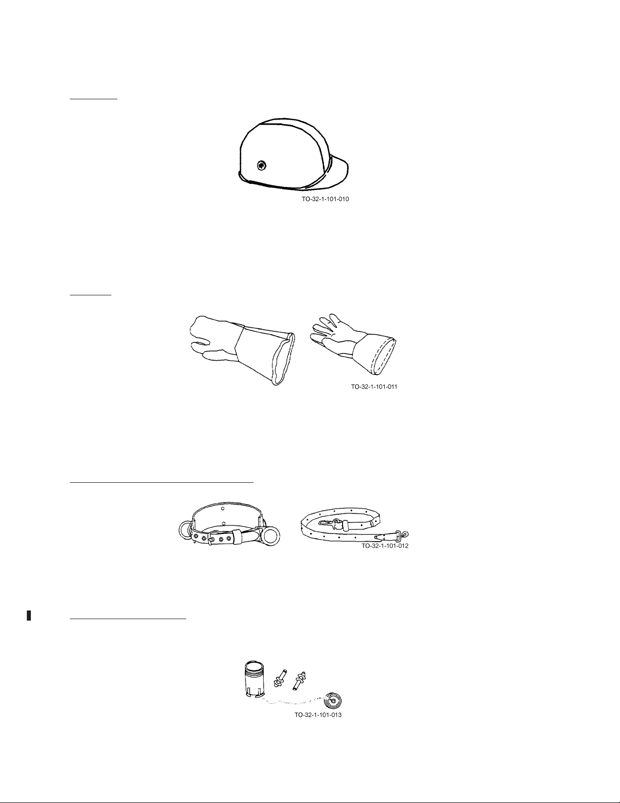
AIR FORCE AIR FORCE TO 32-1-101
ARMY ARMY TM 9-243
MARINE CORPS MARINE CORP TM 10209-10/1
NAVY (NAVAIR) NAVY M6290-AJ-MAN-1010
2.4.3 HELMETS.
Protective helmets (hard hats) come in a variety of shapes. They may be made of tough polyethylene or polycarbonate,
one of the toughest hat materials yet developed. When falling objects strike the hats, the shock-absorbing suspension capabilities minimize injuries. Regular hard hats must be insulated so that personnel may be protected from accidental head
contacts with electrical circuits and equipment at comparatively low voltages (less than 2200 volts). Electrical workers
requiring head protection necessary to their duties or to the working environment, must wear insulating safety helmets or
all-purpose protective helmets which must be capable of withstanding 20,000 volt minimum proof-tests.
2.4.4 GLOVES.
Use gloves whenever you are required to handle rough, scaly, or splintery objects. Two types are shown above. Special
flameproof gloves are designed for gas and electric welding in order to limit danger and damage from sparks and other
hot, flying objects. Personnel working with electricity are usually required to wear insulating rubber gloves. Be sure to
follow all regulations prescribed for the use of gloves. Gloves must not be worn around rotating machinery unless sharp
or rough material is being handled. If such is the case, extreme care should be used to prevent the gloves from being
caught in the machinery.
2.4.5 SAFETY BELTS AND SAFETY STRAPS.
The safety belt and safety strap are a must when working in high places. The safety belt, strapped around the waist, contains pockets for small tools. It also has two D-rings used to attach the safety strap. The safety strap is a nylon-reinforced
leather belt that is placed around the item to be climbed. It is then attached to the two D-rings on the safety belt. Detailed
use of the safety belt and safety strap is described in Chapter 49 of this manual.
2.4.6 HEARING PROTECTION. Proper hearing protection is a must when working with or around certain types of
power tools. Some tools are capable of producing dangerously high noise levels which, if ignored, can result in serious
hearing loss or injury. Use the hearing protection regularly.
2-6

AIR FORCE AIR FORCE TO 32-1-101
MARINE CORPS MARINE CORP TM 10209-10/1
NAVY (NAVAIR) NAVY M6290-AJ-MAN-1010
ARMY ARMY TM 9-243
CHAPTER 3
READING MEASURING SCALES
3.1 READING MEASURING SCALES INTRODUCTION.
The following chapter is designed to provide a basic understanding of how to read scales, dials, and gages. It will not
provide any information on the actual use of the tools. Reference to this chapter will be made throughout the remainder of
the manual.
3.2 READING THE SCALE OF A RULE OR TAPE.
The more common type rules and tapes are divided into fractions, inches, and feet. Explained here are the scales on a 12
inch steel machinist’s rule. The rule is divided into twelve inches. The inches are further divided into eighths, sixteenths,
thirty-seconds, and sixty-fourths. Look at the rule. There is a small numeral marked on the end of the rule nearest the 1 inch
mark. This numeral indicates the number of divisions per inch. When referring to fractions, always use the reduced name.
This is the smallest numerator (top number) and denominator (bottom number). For example, 3/6 can be reduced to 1/2 by
dividing both the top and bottom by 3. Generally, fractions may be reduced to their lowest forms by repeated division by 2
or 3. Look at the section between the “2” and the “3” on the edge marked with an “8” for eighths. There are eight equally
spaced lines. The lengths of these lines differ and indicate different fractions or parts of an inch. The longest line is in the
center and is equal to 4/8 or 1/2 inch. Each half inch is divided in half by a slightly shorter line indicating 2/8 or 1/4 on the
left and 6/8 or 3/4 on the right. Each 1/4 inch is divided in half by the shortest line which indicates 1/8 inch, and will
indicate 1/8, 3/8, 5/8 and 7/8. Now turn the rule and look at the edge with a 16 marked on it. There are now 16 equal
divisions between each inch. Since 2/16 reduces to 1/8, divide each 1/8 into two equal parts producing 1/16, 3/16, 5/16, 7/16,
9/16, 11/16, 13/16, and 15/16. Common tapes and rules usually are not graduated smaller than sixteenths. However, precision measurements require smaller graduations. Look at the back of the machinist’s rule. Find the edge marked 32 and once
again look between the numbers “2” and “3.” To read this rule, remember:
• Sixteen divisions (16/32) are equal to 1/2 inch.
• Eight divisions (8/32) are equal to 1/4 inch.
• Four divisions (4/32) are equal to 1/8 inch.
• Two divisions (2/32) are equal to 1/16 inch.
To read 2-5/8 inches on the scale, first find the two inch mark, then determine the number of 32nds in 5/8. To determine the
number of 32nds in 5/8, remember four divisions or 4/32 are equal to 1/8 inch. If 1/8 is equal to 4/32, then 5/8 is equal to
20/32 as shown:
a. Find the 20/32 reading on the scale as shown above.
b. Write the new fraction 2-20/32 inches.
Finally, look at the edge marked 64. Each inch is now divided into 64 equal parts. To read this rule, remember:
• Thirty-two divisions (32/64) are equal to 1/2 inch.
• Sixteen divisions (16/64) are equal to 1/4 inch.
• Eight divisions (8/64) are equal to 1/8 inch.
• Four divisions (4/64) are equal to 1/16 inch.
3-1

AIR FORCE AIR FORCE TO 32-1-101
ARMY ARMY TM 9-243
MARINE CORPS MARINE CORP TM 10209-10/1
NAVY (NAVAIR) NAVY M6290-AJ-MAN-1010
• Two divisions (2/64) are equal to 1/32 inch.
To read 2-3/4 inches on this scale, first find the two inch mark. Next, determine the number of 64ths in 3/4. To determine the
number of 64ths in 3/4, remember every sixteen divisions or 16/64 are equal to 1/4 inch. If 1/4 is equal to 16/64, then 3/4 is
equal to 48/64 as shown:
3-2

MARINE CORPS MARINE CORP TM 10209-10/1
a. Locate the number 48 between the 2 and 3 inch marks on the scale.
b. Write the new fraction 2-48/64.
AIR FORCE AIR FORCE TO 32-1-101
ARMY ARMY TM 9-243
NAVY (NAVAIR) NAVY M6290-AJ-MAN-1010
3.3 READING A METRIC RULE.
The metric system is based upon multiples of ten. For example, there are 10 millimeters (mm) in a centimeter (cm) and 100
centimeters in a meter. The example provided will deal only with millimeters.
The meter will become the starting point and from this, two additional scales can be developed for measuring. A meter
divided by 100 equals a centimeter, 1/100 or 0.01 meter. Next divide a cm by 10. This will equal a mm, 1/1000 or 0.001
meter.
Now let’s look at a section of the rule between 2 cm and 3 cm. There are 10 equal divisions which are equal to 1/10 cm
or 1 mm. To measure 26 mm, first locate the longest line designated 2 cm or 20 mm. Next count 6 additional lines to find
26 mm. A table for converting from US Common to metric or from metric to US Common may be found inside the back
cover of this manual.
3-3/(3-4 blank)


AIR FORCE AIR FORCE TO 32-1-101
MARINE CORPS MARINE CORP TM 10209-10/1
NAVY (NAVAIR) NAVY M6290-AJ-MAN-1010
ARMY ARMY TM 9-243
CHAPTER 4
TOOL BOXES
4.1 HOW TO CHOOSE AND USE TOOL BOXES.
Types and Uses Paragraph 4.2, provides you with a list of some of the types of tool boxes. These pages should help you
select the right tool box to do the job.
4.2 TOOL BOXES TYPES AND USES.
Tool boxes are used for storing tools. They are usually made of steel, but wood and plastics are also used. Portable tool
boxes are used for carrying and storing a variety of hand tools. Both special and common tools, such as mechanic’s,
electrician, and carpentry tools can be found in tool boxes. Chest-type tool boxes generally contain larger tools, such as
specialized automotive tools or machinist’s tools, requiring a more permanent location. Some larger tool boxes are mounted
on wheels so they can be moved easily from place to place. Tool bags are usually made of canvas. Like the boxes, they are
available in a variety of sizes and serve similar functions. Examples of tool boxes are illustrated below.
4-1

AIR FORCE AIR FORCE TO 32-1-101
ARMY ARMY TM 9-243
MARINE CORPS MARINE CORP TM 10209-10/1
NAVY (NAVAIR) NAVY M6290-AJ-MAN-1010
4-2

AIR FORCE AIR FORCE TO 32-1-101
MARINE CORPS MARINE CORP TM 10209-10/1
NAVY (NAVAIR) NAVY M6290-AJ-MAN-1010
ARMY ARMY TM 9-243
CHAPTER 5
DIVIDERS
5.1 HOW TO CHOOSE AND USE DIVIDERS.
Types and Uses, Paragraph 5.2, provides you with a list of the types of dividers. These pages should help you select the right
dividers for the job. Using a Divider to Scribe a Circle, Paragraph 5.3, tells you how to use the dividers to scribe a circle of
a desired radius. Care of Divider, Paragraph 5.4, tells you how to care for the dividers.
5.2 DIVIDERS TYPES AND USES.
Dividers are instruments used for measuring distances between two points, transferring or comparing measurements directly
from a rule, or for scribing an arc, radius, or circle.
5-1
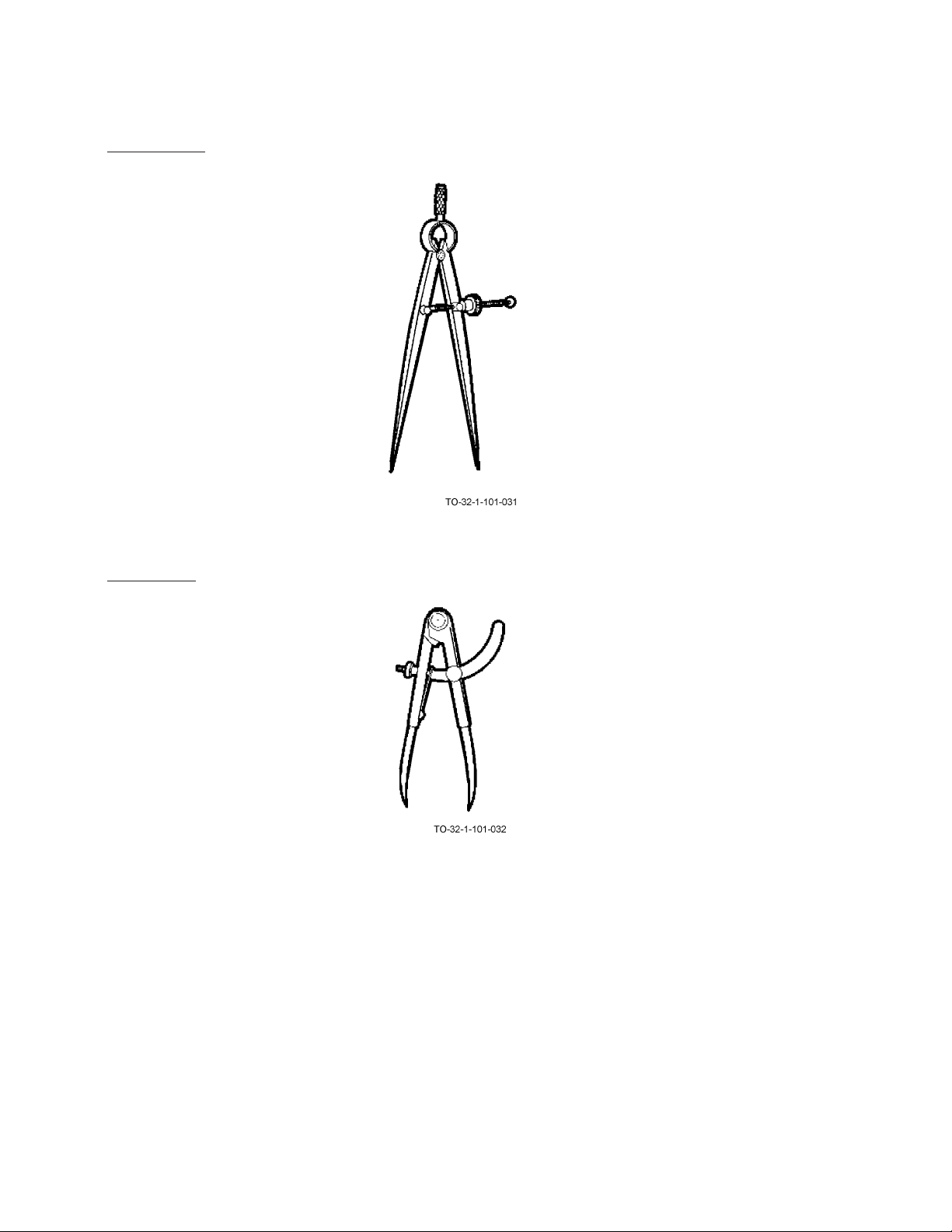
AIR FORCE AIR FORCE TO 32-1-101
ARMY ARMY TM 9-243
MARINE CORPS MARINE CORP TM 10209-10/1
NAVY (NAVAIR) NAVY M6290-AJ-MAN-1010
5.2.1 Spring Divider.
A spring divider consists of two sharp points at the end of straight legs, held apart by a spring and adjusted by means of
a screw and nut. The spring divider is available in sizes from 3 to 10 inches in length.
5.2.2 Wing Divider.
A wing-type divider has a steel bar that separates the legs, a lock nut for setting a rough measurement, and an adjustment
screw for fine adjustments. The wing-type divider is available in 6, 8, and 12 inch lengths. Also available is a divider
with one removable leg, so that a pencil may be inserted.
5-2
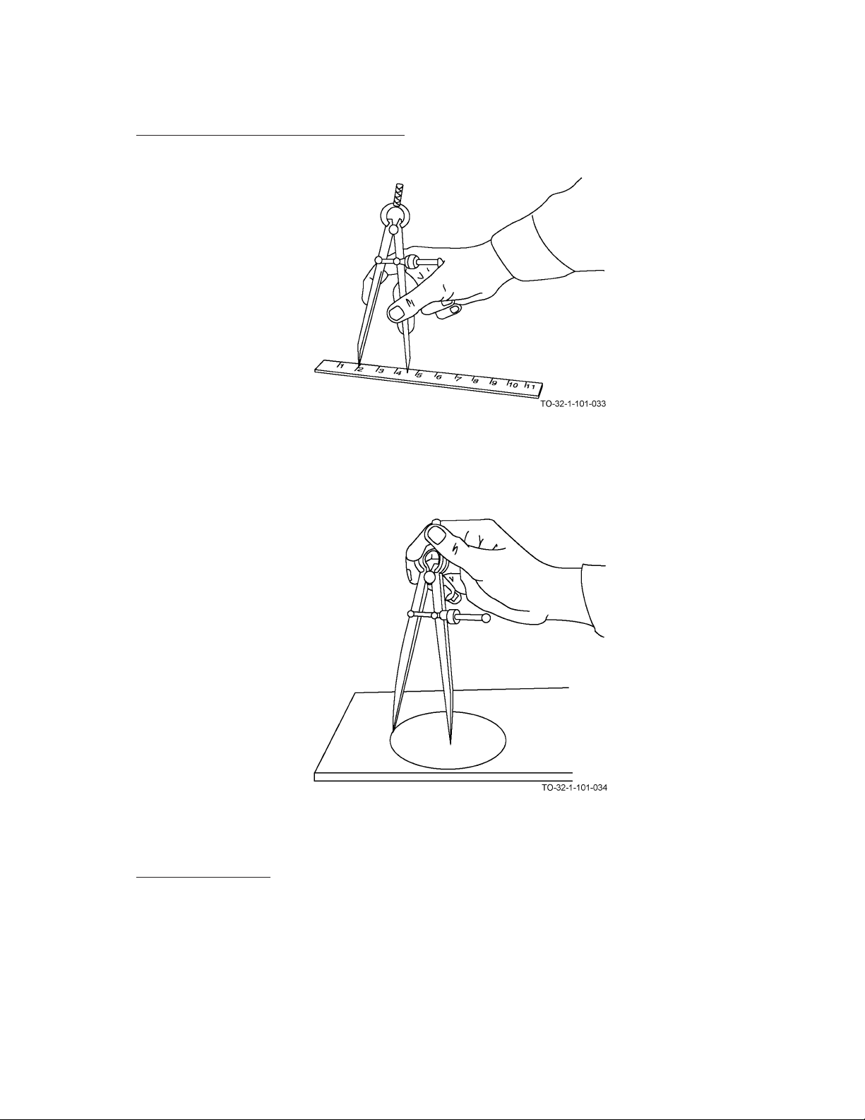
MARINE CORPS MARINE CORP TM 10209-10/1
NAVY (NAVAIR) NAVY M6290-AJ-MAN-1010
5.3 USING A DIVIDER TO SCRIBE A CIRCLE.
a. Set the desired radius on the dividers using the appropriate graduations on a rule.
AIR FORCE AIR FORCE TO 32-1-101
ARMY ARMY TM 9-243
b. Place the point of one of the divider legs on the point to be used as the center.
c. Lean the dividers in the direction of movement and scribe the circle by revolving the dividers.
5.4 CARE OF DIVIDERS.
Keep dividers clean and dry. Protect the points against damage. Store dividers where they will not become bent or broken.
5-3/(5-4 blank)


AIR FORCE AIR FORCE TO 32-1-101
MARINE CORPS MARINE CORP TM 10209-10/1
NAVY (NAVAIR) NAVY M6290-AJ-MAN-1010
ARMY ARMY TM 9-243
CHAPTER 6
CALIPERS
6.1 HOW TO CHOOSE AND USE CALIPERS.
Types and Uses, Paragraph 6.2, provides you with a list of types of calipers. These pages should help you select the right
calipers for the job. Reading Calipers Paragraph 6.3, tells you how to read special calipers for accurate measurements. By
becoming familiar with this procedure, you will learn to make accurate measurements. Care of Calipers, Paragraph 6.5, tells
you how to keep your calipers in good condition.
6.2 CALIPERS TYPES AND USES.
Calipers are used to measure diameters. Outside calipers measure outside diameters. Inside calipers measure inside diameters. Simple calipers are used along with a scale to find the measurement. Slide calipers and vernier calipers have their own
scales.
6-1

AIR FORCE AIR FORCE TO 32-1-101
ARMY ARMY TM 9-243
MARINE CORPS MARINE CORP TM 10209-10/1
NAVY (NAVAIR) NAVY M6290-AJ-MAN-1010
6.2.1 Simple Calipers.
The simple outside calipers are bowlegged. Those used for inside diameters have straight legs with feet turned outward.
Calipers are adjusted by pulling or pushing the legs to open or close them.
6.2.2 Spring-Joint Calipers.
The spring-joint calipers have the same type of legs, but are joined by a strong spring hinge, screw, and adjustment nut.
6-2
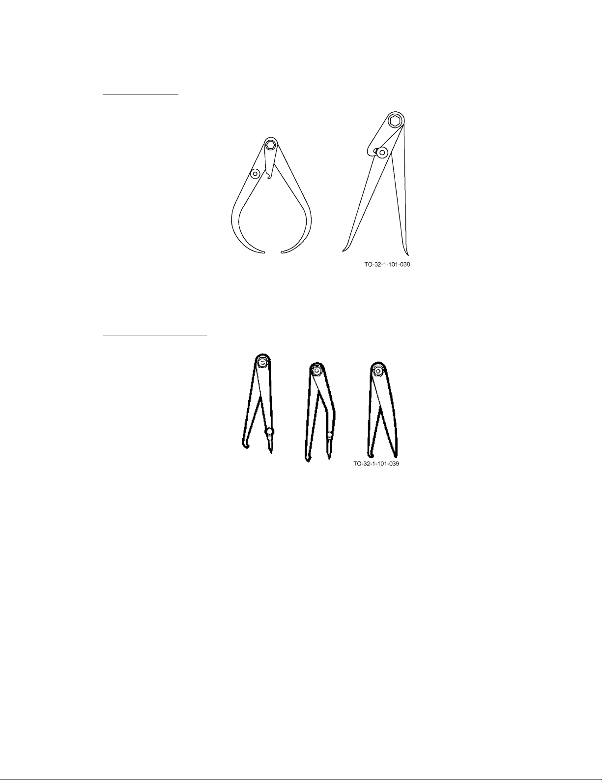
AIR FORCE AIR FORCE TO 32-1-101
MARINE CORPS MARINE CORP TM 10209-10/1
NAVY (NAVAIR) NAVY M6290-AJ-MAN-1010
6.2.3 Transfer Calipers.
Transfer calipers are used for measuring chamfered grooves or flanges. A screw attaches a small auxiliary leaf to one of
the legs. The measurement is made as with ordinary calipers. The leaf is locked to the leg. The legs may be opened or
closed as needed to clear the obstruction. The legs are then brought back and locked to the leaf, restoring them to the
original setting.
ARMY ARMY TM 9-243
6.2.4 Hermaphrodite Calipers.
The hermaphrodite calipers have one straight leg ending in a sharp point. On some models this point is removable. This
leg is usually bowlegged. This caliper is used for finding shaft centers or locating shoulders.
6-3
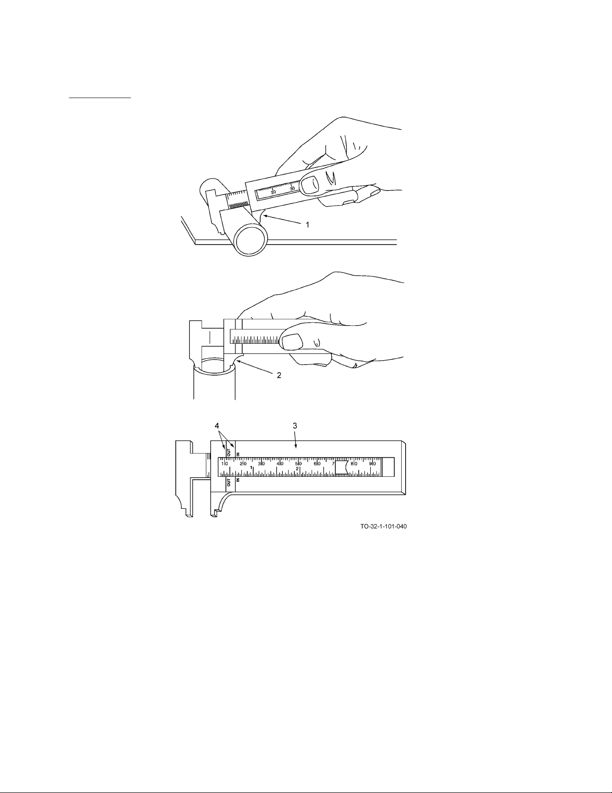
AIR FORCE AIR FORCE TO 32-1-101
ARMY ARMY TM 9-243
MARINE CORPS MARINE CORP TM 10209-10/1
NAVY (NAVAIR) NAVY M6290-AJ-MAN-1010
6.2.5 Slide Calipers.
Slide calipers can be used for measuring outside and inside dimensions. Graduations are in inches, fractions, or millimeters. As shown above, one side of the caliper is used to measure outside (1) and the other side is used to measure inside
(2) dimensions. Stamped on the frame (3) are the words “IN”. and “OUT” (4). You use them when taking inside and outside measurements. The other side of the caliper is used as a straight measuring rule. If necessary, see Chapter 3 of this
manual for reading scales and rules.
6-4

6.2.6 Vernier Calipers.
AIR FORCE AIR FORCE TO 32-1-101
ARMY ARMY TM 9-243
MARINE CORPS MARINE CORP TM 10209-10/1
NAVY (NAVAIR) NAVY M6290-AJ-MAN-1010
Vernier calipers work like slide calipers. As shown above, vernier calipers can make very accurate outside or inside measurements. A vernier caliper is used by loosening the two locking screws (1) and (2). This allows the movable jaw (3) to
move along the rule until desired position is obtained. The locking screw (1) is then retightened securing the movable jaw
(3). Any fine adjustments to the vernier scale (4) are then made using adjustment control (5). Locking screw (2) is then
secured and vernier caliper is ready to read.
6-5
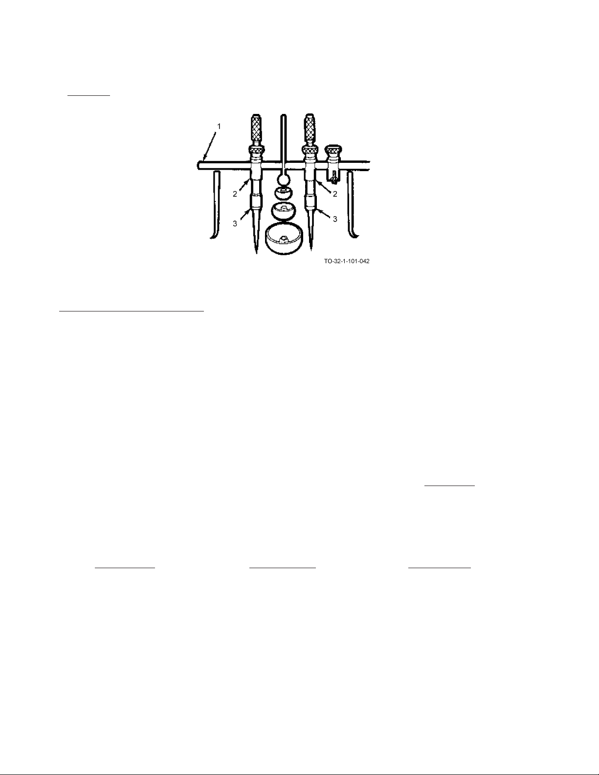
AIR FORCE AIR FORCE TO 32-1-101
ARMY ARMY TM 9-243
MARINE CORPS MARINE CORP TM 10209-10/1
NAVY (NAVAIR) NAVY M6290-AJ-MAN-1010
6.2.7 Trammels.
The trammel measures distances beyond the range of calipers. The instrument consists of a rod or beam (1) to which
trams (2) are clamped. The trams (2) carry chucks (3). The trammel can also be used as a divider by changing the points.
6.3 READING A VERNIER CALIPER.
To read a vernier caliper you must be able to understand both the steel rule and vernier scales. The steel rule (1) is graduated
in 0.025 of an inch. Every fourth division (2) (representing a tenth of an inch) is numbered. The vernier scale (3) is divided
into 25 parts and numbered 0, 5, 10, 15, 20, and 25. These 25 parts are equal to 24 parts on the steel rule (1). The difference
between the width of one of the 25 spaces on the vernier scale (3) and one of the 24 spaces on the steel rule (1) is 1/1000
of an inch.
Read the measurement as shown above.
Read the number of whole inches on the top scale (1) to the left of the vernier zero index (4)
1.000 inch
and record.
Read the number of tenths (5) to the left of the vernier zero index (4) and record. 0.400 inch
Read the number of twenty-fifths (6) between the tenths mark (5) and the zero index (4) and
3 x 0.025 = 0.075 inch
record.
Read the highest line on the vernier scale (3) which lines up with the lines on the top scale
11/25 or 0.011 inch
(7) and record. (Remember 1/25 = 0.001 inch.)
TOTAL 1.486 inches
Most vernier calipers read “OUTSIDE” on one side and “INSIDE” on the other side. If a scale isn’t marked, and you
want to take an inside measurement, read the scale as you would for an outside diameter. Then add the measuring point
allowance by referring to manufacturer’s instructions or the following table.
Size of Caliper
English Measure Metric Measure
6 inch or 150 millimeter (mm) Add 0.250 inch Add 8.35 mm
12 inch or 300 mm 0.300 inch 7.62 mm
24 inch or 600 mm 0.300 inch 7.62 mm
36 inch or 600 mm 0.500 inch 12.70 mm
6-6
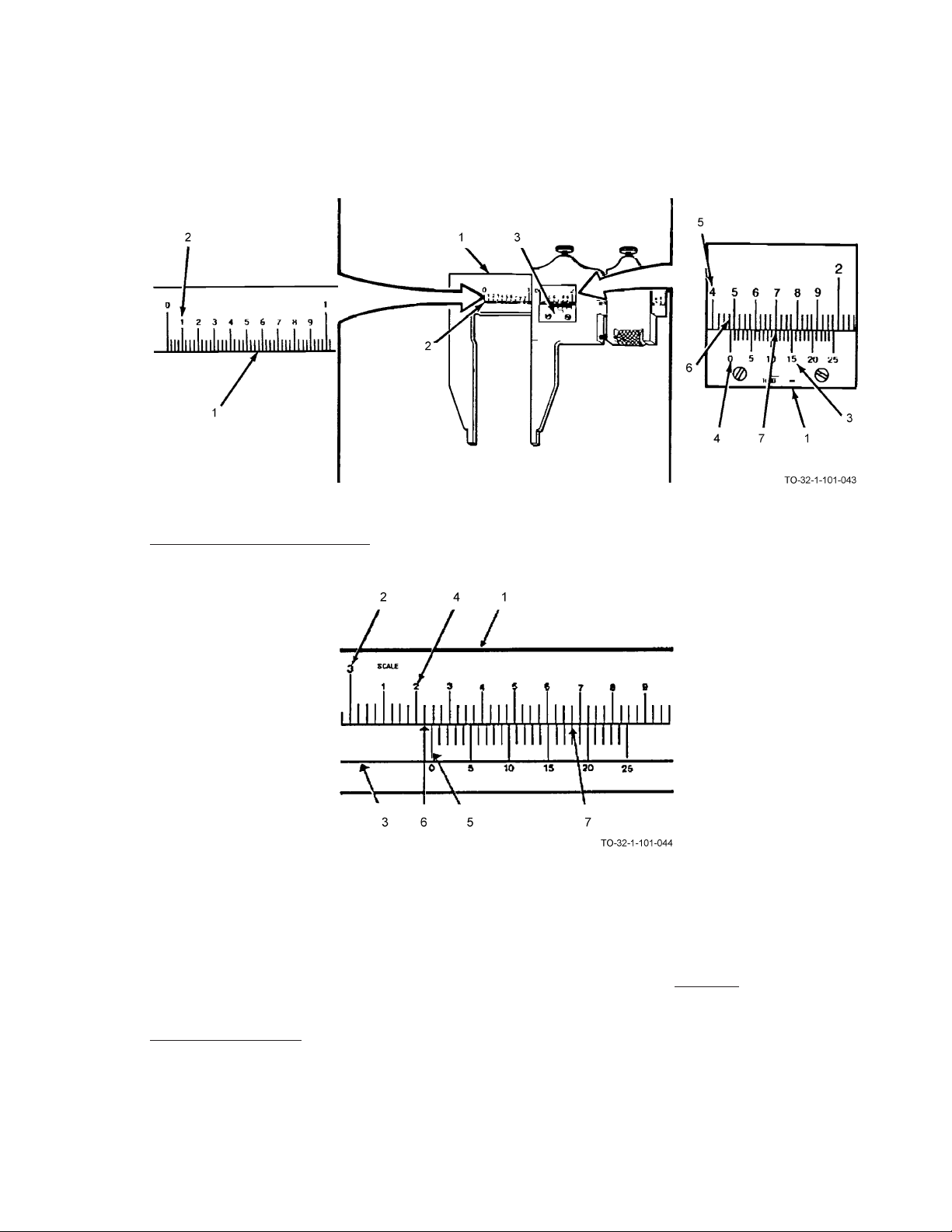
AIR FORCE AIR FORCE TO 32-1-101
MARINE CORPS MARINE CORP TM 10209-10/1
NAVY (NAVAIR) NAVY M6290-AJ-MAN-1010
ARMY ARMY TM 9-243
6.4 READING A METRIC CALIPER.
The steel rule (1) is divided into centimeters (cm) (2) and the longest lines represent 10 mm each. Each millimeter is divided into quarters. The vernier scale (3) is divided into 25 parts and is numbered 0, 5, 10, 15, 20 and 25.
Read the total number of mm (4) to the left of the vernier zero index (5) and record 32.00 cm
Read the number of quarters (6) between the mm mark and the zero index and record 25 mm = (1 quarter)
Read the highest line on the vernier scale (3) which lines up with the line on the
scale (7) and record
TOTAL 32.43 mm
18 mm
6.5 CARE OF CALIPERS.
a. As needed, coat metal parts of all calipers with a light coat of oil to prevent rust.
b. Store calipers in separate containers provided.
6-7

AIR FORCE AIR FORCE TO 32-1-101
ARMY ARMY TM 9-243
MARINE CORPS MARINE CORP TM 10209-10/1
NAVY (NAVAIR) NAVY M6290-AJ-MAN-1010
c. Keep graduations and markings on all calipers clean and legible.
d. Do not drop any caliper. Small nicks or scratches can cause inaccurate measurements.
e. Protect caliper points from damage.
6-8

AIR FORCE AIR FORCE TO 32-1-101
MARINE CORPS MARINE CORP TM 10209-10/1
NAVY (NAVAIR) NAVY M6290-AJ-MAN-1010
ARMY ARMY TM 9-243
CHAPTER 7
MICROMETERS
7.1 HOW TO CHOOSE AND USE MICROMETERS.
Types and Uses, Paragraph 7.2, provides you with a list of the types of micrometers. These pages should help you select the
right micrometer for the job. Reading Micrometers, Paragraph 7.4, tells you how to read the different varieties of micrometers. By becoming familiar with the procedures you will learn to make accurate measurements.
7.2 MICROMETERS TYPES AND USES.
Micrometers are instruments used to measure distances to the nearest one-thousandth of an inch. The measurement is usually
expressed or written as a decimal. There are three types of micrometers which are commonly used: the outside micrometer,
the inside micrometer, and the depth micrometer.
7.2.1 Outside Micrometers.
Outside micrometers are used to measure an outside distance or diameter to an accuracy of 0.001 of an inch.
7-1

AIR FORCE AIR FORCE TO 32-1-101
ARMY ARMY TM 9-243
MARINE CORPS MARINE CORP TM 10209-10/1
NAVY (NAVAIR) NAVY M6290-AJ-MAN-1010
7.2.2 Inside Micrometers.
Inside micrometers are used to measure an inside diameter to an accuracy of 0.001 of an inch. ID micrometers have a
range of 0.500 when used with one-half inch spacers.
7.2.3 Depth Micrometers.
Depth micrometers are used to measure depths to an accuracy of 0.001 inches.
7-2

7.3 SELECTING THE PROPER MICROMETER.
AIR FORCE AIR FORCE TO 32-1-101
ARMY ARMY TM 9-243
MARINE CORPS MARINE CORP TM 10209-10/1
NAVY (NAVAIR) NAVY M6290-AJ-MAN-1010
7-3

AIR FORCE AIR FORCE TO 32-1-101
ARMY ARMY TM 9-243
MARINE CORPS MARINE CORP TM 10209-10/1
NAVY (NAVAIR) NAVY M6290-AJ-MAN-1010
The types of micrometers commonly used are made so that the longest movement possible between the spindle and the
anvil is 1 inch. This movement is called the “range.” The frames of micrometers, however, are available in a wide variety
of sizes, from 1 inch up to as large as 24 inches. The range of a 1 inch micrometer is from 0 to 1 inch. In other words, it
can be used to work where the part to be measured is 1 inch or less. A 2 inch micrometer has a range from 1 inch to 2
inches, and will measure only work between 1 and 2 inches thick. A 6 inch micrometer has a range from 5 to 6 inches,
and will measure only work between 5 and 6 inches thick. It is necessary, therefore, that the mechanic first find the approximate size of the work to the nearest inch, and then select a micrometer that will fit it. For example, to find the exact
diameter of a piece of round stock use a rule and find the approximate diameter of the stock. If it is found to be approximately 3-1/4 inches, a micrometer witha3to4inch range would be required to measure the exact diameter. Similarly,
with inside and depth micrometers, rods of suitable lengths must be fitted into the tool to get the approximate dimension
within an inch, after which the exact measurement is read by turning the thimble. The size of a micrometer indicates the
size of the largest work it will measure.
7-4

AIR FORCE AIR FORCE TO 32-1-101
MARINE CORPS MARINE CORP TM 10209-10/1
NAVY (NAVAIR) NAVY M6290-AJ-MAN-1010
7.4 READING A STANDARD MICROMETER.
Reading a micrometer is only a matter of reading the micrometer scale or counting the revolutions of the thimble and
adding to this any fraction of a revolution. The micrometer screw has 40 threads per inch. This means that one complete
and exact revolution of the micrometer screw (1) moves the spindle (2) away from or toward the anvil (3) exactly 1/40 or
0.025 inch.
ARMY ARMY TM 9-243
The lines on the barrel (4) conform to the pitch of the micrometer screw (1), each line indicating 0.025 inch, and each
fourth line being numbered 1, 2, 3, and so forth. The beveled edge of the thimble is graduated into 25 parts, each line
indicating 0.001 inch, or 0.025 inch covered by one complete and exact revolution of the thimble. Every fifth line on the
thimble is numbered to read a measurement in thousandths of an inch.
7.4.1 To Read a Measurement as Shown in the Paragraph Above:.
Read highest figure visible, on barrel (5). 2 = 0.200 inches
Number of lines visible between the Number (No.) 2 and thimble edge (6). 1 = 0.025 inches
The line on the thimble that coincides with or has passed the revolution or long line in the
barrel (7).
TOTAL = 0.241 inches
16 = 0.016 inches
7-5

AIR FORCE AIR FORCE TO 32-1-101
ARMY ARMY TM 9-243
MARINE CORPS MARINE CORP TM 10209-10/1
NAVY (NAVAIR) NAVY M6290-AJ-MAN-1010
7.5 READING A VERNIER MICROMETER.
Reading the vernier micrometer is the same as reading the standard micrometer.An additional step must be taken, to add the
vernier reading to the dimensions. This allows for precise measurements which are accurate to ten-thousandths (0.0001) of
an inch. This scale furnishes the fine readings between the lines on the thimble rather than making an estimate as you would
on a standard micrometer.
The ten spaces on the vernier (1) are equivalent to 9 spaces on the thimble (2). Therefore, each unit on the vernier scale
is equal to 0.0009 inch and the difference between the sizes of the units on each scale is 0.0001 inch.
7.5.1 To Read a Measurement as Shown Above:.
Read highest figure visible on barrel (3). 2 = 0.200 inches
Number of lines visible between the Number (No.) 2 and thimble edge (4). 3 = 0.075 inches
The line on the thimble that coincides with or is nearest the revolution or long line
in the barrel (5).
The line on the vernier scale that coincides with the line on the thimble (6). 2 =
TOTAL = 0.2862 inches
7-6
11 = 0.011 inches
0.0002 inches

AIR FORCE AIR FORCE TO 32-1-101
MARINE CORPS MARINE CORP TM 10209-10/1
NAVY (NAVAIR) NAVY M6290-AJ-MAN-1010
7.6 READING A METRIC MICROMETER.
The same principle is applied in reading the metric graduated micrometer, but the following changes in graduations are used:
The pitch of the micrometer screw is 0.05 millimeters (mm). One revolution of the spindle advances or withdraws the screw
a distance equal to 0.5 mm.
The barrel (1) is graduated in millimeters from 0 to 25. It takes two revolutions of the spindle to move the barrel 1 mm.
The thimble (2) is graduated in 56 divisions with every fifth line being numbered. Rotating the thimble from one graduation to the next moves the spindle 1/50 of 0.5 mm, or 1/100 mm. Two graduations equal 2/100 mm, and so forth.
ARMY ARMY TM 9-243
7.6.1 To Read a Measurement as Shown Above.
Read highest figure visible on barrel (1). 20 = 20.0 mm
Number of lines visible between the No. 20 and thimble edge (2). 2 = 2.0 mm
The line on the thimble that coincides with or has passed the revolution or long
line in the barrel (3).
NOTE
Remember that 1 revolution is 0.5 mm. It takes 2 revolutions to move 1 mm.
Measurement reading. TOTAL 22.36 mm
7.7 CARE OF MICROMETERS.
a. As needed, coat metal parts of all micrometers with a light coat of oil to prevent rust.
b. Store micrometers in separate containers provided by manufacturer.
c. Keep graduations and markings on all micrometers clean and legible.
d. Do not drop any micrometer. Small nicks or scratches can cause inaccurate measurements.
36 = 36/100 (36) mm
7-7/(7-8 blank)

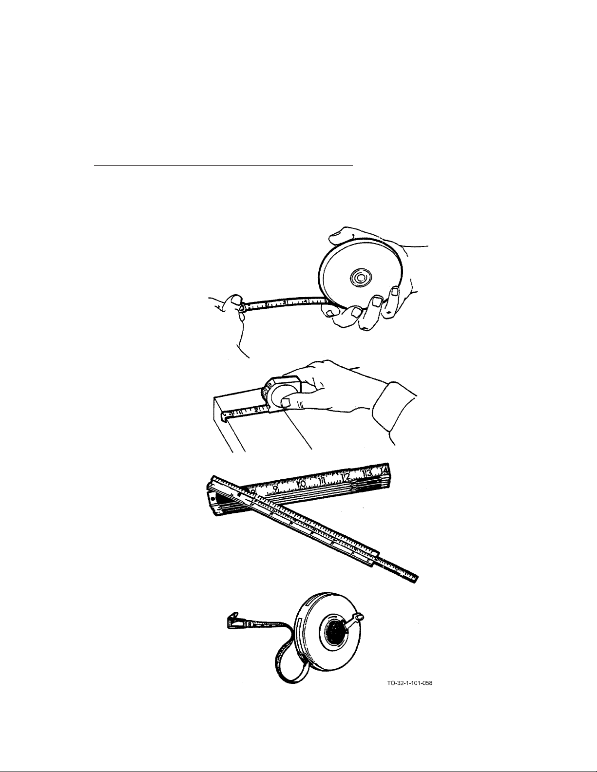
AIR FORCE AIR FORCE TO 32-1-101
MARINE CORPS MARINE CORP TM 10209-10/1
NAVY (NAVAIR) NAVY M6290-AJ-MAN-1010
ARMY ARMY TM 9-243
CHAPTER 8
RULES AND STEEL TAPES
8.1 HOW TO CHOOSE AND USE RULES AND STEEL TAPES.
Types and Uses, Paragraph 8.2, provides you with a list of the types of rules and tapes. These pages should help you select
the right rule or tape for the job. Using Rules and Tapes, Paragraph 8.3, tells you how to use the various types of measuring
instruments. Care of Rules and Tapes, Paragraph 8.4, tell you how to care for rules and tapes.
8-1

AIR FORCE AIR FORCE TO 32-1-101
ARMY ARMY TM 9-243
MARINE CORPS MARINE CORP TM 10209-10/1
NAVY (NAVAIR) NAVY M6290-AJ-MAN-1010
8.2 RULES AND STEEL TAPES TYPES AND USES.
The rule or tape is used for measuring where accuracy is not an extremely critical factor. They can be rigid or flexible, come
in various lengths, and can be made of wood, metal, cloth, or fiberglass.
8.2.1 Rules.
The rule is the most common of measuring tools. This rule is usually 6 or 12 inches in length, although other lengths are
available. Steel rules may be flexible or non-flexible, but the thinner the rule, the easier it is to measure accurately because the division marks are closer to the work.
A rule usually has four sets of graduations, one on each edge of each side. The longest lines represent the inch marks. On
one edge each inch is divided into 8 equal spaces so each space represents 1/8 inch The other edge of this side is divided
in sixteenths. The 1/4 inch and 1/2 inch marks are commonly made longer than the smaller division marks to facilitate
counting, but the graduations are usually not numbered individually, as they are sufficiently far apart to be counted without difficulty. The opposite side is similarly divided into 32 and 64 spaces per inch, and it is common practice to number
every fourth division for easier reading.
There are many variations of the common rule. Sometimes the graduations are on one side only, sometimes a set of
graduations is added across one end for measuring in narrow spaces, and sometimes only the first inch is divided into
64ths, with the remaining inches divided into 32nds and 16ths. A metal or wood folding rule may be used.
8-2

AIR FORCE AIR FORCE TO 32-1-101
MARINE CORPS MARINE CORP TM 10209-10/1
NAVY (NAVAIR) NAVY M6290-AJ-MAN-1010
8.2.2 Folding Rules.
These folding rules are usually from two to six feet long. The folding rules cannot be relied on for extremely accurate
measurements because a certain amount of play develops at the joints after continued use.
8.2.3 Steel Tapes.
ARMY ARMY TM 9-243
Steel tapes are made from 6 to about 300 feet in length. The shorter tapes are made with a curved, but rigid, cross section
flexible enough to be rolled up. Long, flat tapes need support over their full length to avoid sagging. Lack of support can
cause reading errors. The most common types of steel tapes have a hook at one end to let one person take all the readings.
8-3
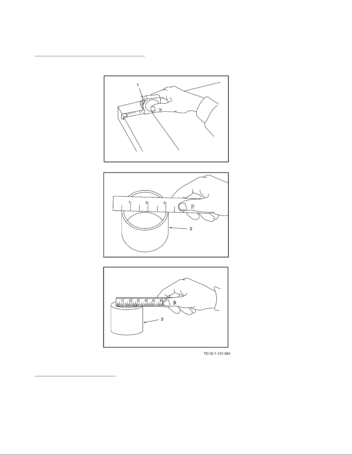
AIR FORCE AIR FORCE TO 32-1-101
ARMY ARMY TM 9-243
MARINE CORPS MARINE CORP TM 10209-10/1
NAVY (NAVAIR) NAVY M6290-AJ-MAN-1010
8.3 USING RULERS AND TAPES EXAMPLES.
8.4 CARE OF RULES AND TAPES.
1. Keep rules and tapes clean and dry.
8-4
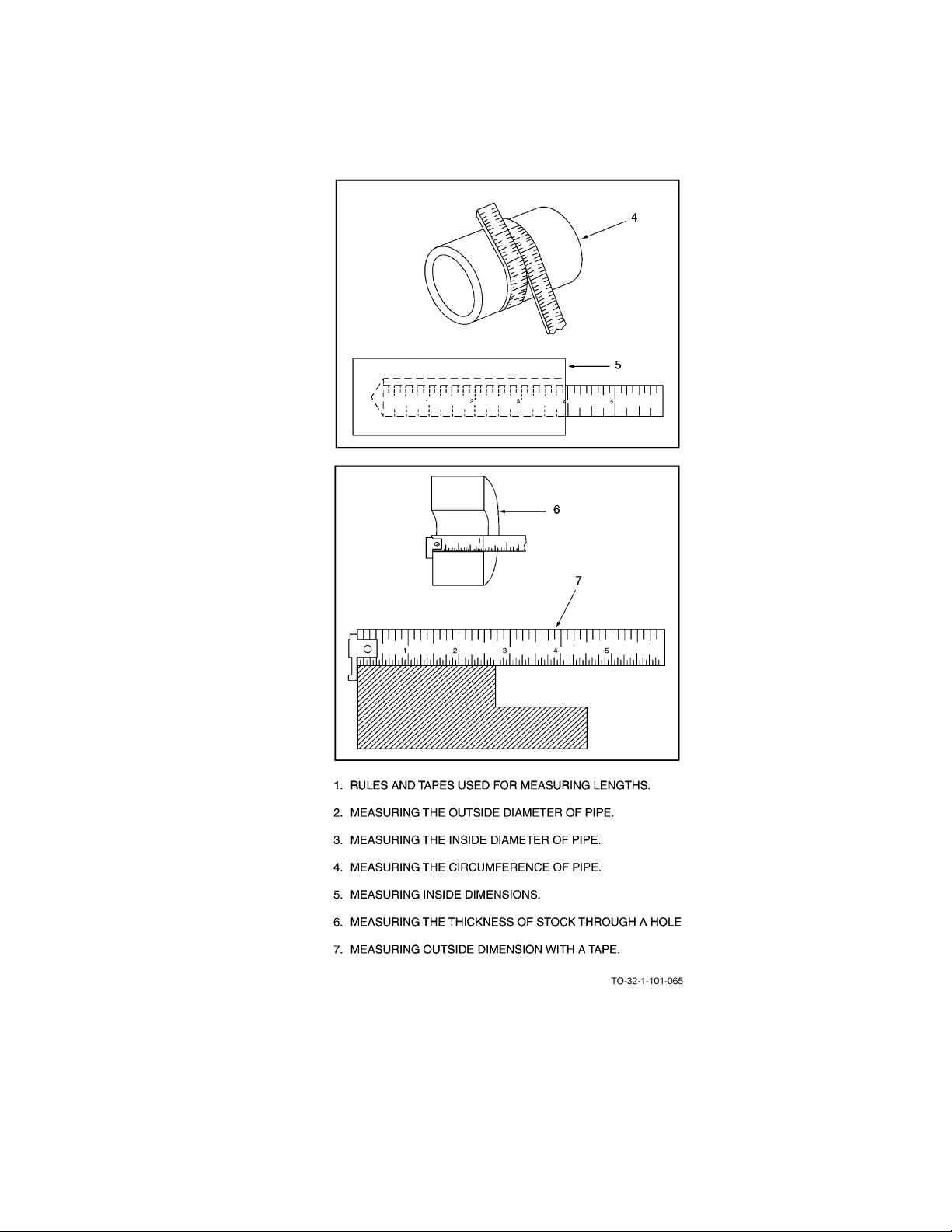
MARINE CORPS MARINE CORP TM 10209-10/1
NAVY (NAVAIR) NAVY M6290-AJ-MAN-1010
2. Store rules and tapes where they will not become bent or damaged.
AIR FORCE AIR FORCE TO 32-1-101
ARMY ARMY TM 9-243
8-5/(8-6 blank)


AIR FORCE AIR FORCE TO 32-1-101
MARINE CORPS MARINE CORP TM 10209-10/1
NAVY (NAVAIR) NAVY M6290-AJ-MAN-1010
ARMY ARMY TM 9-243
CHAPTER 9
MISCELLANEOUS MEASURING TOOLS
9.1 HOW TO CHOOSE AND USE MISCELLANEOUS MEASURING TOOLS.
Types and Uses, Paragraph 9.2, provides you with a list of the more common types of miscellaneous measuring tools. These
pages should help you select the right measuring tool for the job. Using, Paragraph 9.3, tells you how to use several of these
tools for a certain application. Although there are many other uses for these tools, you should be able to perform most any
task by becoming familiar with the procedures outlined in these pages. Care of Miscellaneous Measuring Tools, Paragraph
9.4, tells how to care for your measuring tools.
9.2 MISCELLANEOUS MEASURING TOOLS TYPES AND USES.
9.2.1 Adjustable Parallel.
Adjustable parallels consist of two tapered parts fitted together. The distance between the two outside parallel surfaces
varies by moving mating parts together or apart. This distance is then measured with a micrometer. Adjustable parallels
are used as gages for leveling and setup work. Adjustable parallels are available in various sizes depending on the nature
of work.
9-1

AIR FORCE AIR FORCE TO 32-1-101
ARMY ARMY TM 9-243
MARINE CORPS MARINE CORP TM 10209-10/1
NAVY (NAVAIR) NAVY M6290-AJ-MAN-1010
9.2.2 V-Block and Clamp.
The V-block and clamp assembly consists of a V-shaped, hardened steel body to support round, square, or rectangular
shaped work. A clamp (or clamps) holds the work firmly in the body groove. V-blocks and clamps are especially used for
grinding, milling, or drilling purposes. Various styles and designs of V-blocks and clamps are available depending on application.
9.2.3 Angle Plates.
Angle plates are devices consisting of two flat outside working surfaces jointed at right angles. The outside work surfaces
are precision ground. The standard angle plate is permanently jointed at a right angle. However, an adjustable type with
varying angle adjustments is also available. Angle plates are used for clamping or holding work vertically. They are also
used for layout, inspection, or machine set-up. Various sizes and designs are available depending on the task.
9-2

AIR FORCE AIR FORCE TO 32-1-101
MARINE CORPS MARINE CORP TM 10209-10/1
NAVY (NAVAIR) NAVY M6290-AJ-MAN-1010
9.2.4 Magnetic Base Indicator Holder.
The magnetic base indicator holder is a one-piece metal assembly that attaches to the work surface magnetically. A gage
or indicator attaches to the assembly. Base indicator holders are used for attaching gages to lathes, milling machines,
shapers, or any machine where graduations are difficult to read. Magnetic base indicator holders are available in many
sizes and designs depending on application.
ARMY ARMY TM 9-243
9.2.5 Registering Speed Indicators.
Registering speed indicators are designed to count the number of revolutions of wheels, shafts, etc. Revolutions are
counted by attaching spindle of speed indicator to hub of shaft or wheel. Indicator spindle will turn in either direction
counting each revolution on a circular dial. Various designs of speed indicators are available depending on nature of use.
9-3
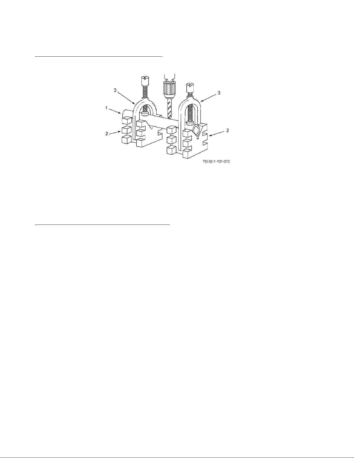
AIR FORCE AIR FORCE TO 32-1-101
ARMY ARMY TM 9-243
MARINE CORPS MARINE CORP TM 10209-10/1
NAVY (NAVAIR) NAVY M6290-AJ-MAN-1010
9.3 USING MISCELLANEOUS MEASURING TOOLS.
a. Place pipe (1) in V-blocks (2).
b. Secure pipe (1) in position using screw clamps (3).
c. Begin drilling at desired spot on pipe (1).
9.4 CARE OF MISCELLANEOUS MEASURING TOOLS.
a. Clean all tools thoroughly after using.
b. As needed, apply a light coat of oil to all exposed metal parts to avoid rusting.
c. To avoid possible damage to sensitive tools, store tools in proper locations.
9-4

AIR FORCE AIR FORCE TO 32-1-101
MARINE CORPS MARINE CORP TM 10209-10/1
NAVY (NAVAIR) NAVY M6290-AJ-MAN-1010
ARMY ARMY TM 9-243
CHAPTER 10
LEVELS
10.1 HOW TO CHOOSE AND USE LEVELS.
Types and Uses, Paragraph 10.2, provides you with a list of types of levels. These pages should help you select the right
level for the job. Using a Level, Paragraph 10.3, tells you how to use levels for their various functions (plumbing, leveling,
etc).
10.2 LEVELS TYPES AND USES.
Levels are tools designed to prove whether a plane or surface is in the true vertical or true horizontal. All levels consist of a
liquid-filled glass tube or tubes supported in a frame.
10.2.1 Master Precision Level.
The master precision level has a ground and graduated main vial (1). The top and bottom of the level are milled and
ground to make sure both surfaces are absolutely parallel. This level is used to determine the true horizontal with the
main vial (1). The true vertical is determined by using the two smaller vials (2).
10-1
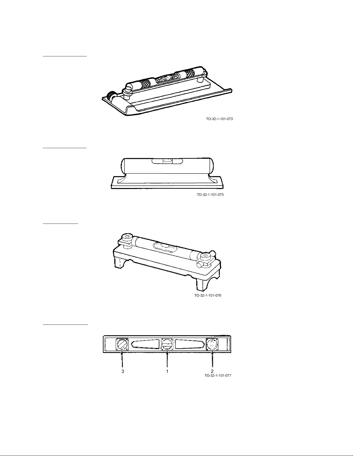
AIR FORCE AIR FORCE TO 32-1-101
ARMY ARMY TM 9-243
MARINE CORPS MARINE CORP TM 10209-10/1
NAVY (NAVAIR) NAVY M6290-AJ-MAN-1010
10.2.2 Machinist’s Level.
The machinist’s level has an extra large vial. This increases its accuracy and sensitivity. Some of these levels have
grooved bottoms which fit over pipes and shafts. They are used in machine shops for leveling work and equipment.
10.2.3 Iron Bench Level.
The iron bench level is made of a special design casting which insures its lightness, strength, and rigidity. It is used
mostly in the construction industry. It may also be used in a machine shop.
10.2.4 Striding Level.
The iron bench level is made of a special design casting which insures its lightness, strength, and rigidity. It is used
mostly in the construction industry. It may also be used in a machine shop.
10.2.5 Carpenter’s Level.
The carpenter’s level has three vials which are mounted horizontally (1), vertically (2), and at a 45 degree angle (3). The
10-2

AIR FORCE AIR FORCE TO 32-1-101
MARINE CORPS MARINE CORP TM 10209-10/1
NAVY (NAVAIR) NAVY M6290-AJ-MAN-1010
carpenter’s level is used in construction for checking for true vertical, true horizontal, and 45 degree angles.
Some levels have a bent tube (4) which allows the bubble to settle quickly.
10.2.6 Line Level.
The line level is a single vial in a metal case with a hook on each end for hanging on a cord. It is used to check whether
two points are level, such as two points on a floor or in an elevation. It must be used with a tightly stretched cord.
10.3 USING A LEVEL.
ARMY ARMY TM 9-243
A level may be checked for accuracy by placing it on a known level surface and noting the position of the bubble. Reverse
the level end for end. Observe the position of the bubble. If the relative position of the bubble was the same for both
readings, the level is accurate.
10.3.1 Horizontal Surface.
Place the level on a flat horizontal surface. Check the horizontal vial (1). The bubble should be between the two etched
lines on the vial. If it is not, the surface is not horizontal.
10-3

AIR FORCE AIR FORCE TO 32-1-101
ARMY ARMY TM 9-243
MARINE CORPS MARINE CORP TM 10209-10/1
NAVY (NAVAIR) NAVY M6290-AJ-MAN-1010
10.3.2 Angled Surface.
Place the level on an angled surface. If the angle is 45 degrees, the bubble will appear between the notched lines on the
45 degree vial (2).
10.3.3 Vertical Surface.
Place the level against a flat vertical surface. Check the vertical vial (3). The bubble should be between the two etched
lines on the vial. If it is not, the surface is not vertical.
10-4

AIR FORCE AIR FORCE TO 32-1-101
MARINE CORPS MARINE CORP TM 10209-10/1
NAVY (NAVAIR) NAVY M6290-AJ-MAN-1010
ARMY ARMY TM 9-243
CHAPTER 11
PLUMB BOBS
11.1 HOW TO CHOOSE AND USE PLUMB BOBS.
Types and Uses, Paragraph 11.2, provides you with a list of the more common types of plumb bobs. These pages should help
you select the right plumb bob for the job. Using a Plumb Bob, Paragraph 11.3, tells you how to use a steel plumb bob to
establish the true vertical of a square post. By becoming familiar with this procedure you will build a good background for
using other plumb bobs. Care of Plumb Bobs, Paragraph 11.4, tells you how to keep your plumb bobs in proper condition.
11.2 PLUMB BOBS TYPES AND USES.
11.2.1 Plumb Bobs. A plumb bob is a precision instrument used to establish a true vertical transfer and line-up reference
point, and to take readings or soundings in tanks and voids. Plumb bobs are used by carpenters, surveyors and maintenance
technicians.
11.2.2 Surveyor’s Polished Brass.
The surveyor’s brass plumb bob may be either a spool type (A) or an adjustable cap type (B). Both types have replaceable steel points for increased accuracy. The adjustable cap allows the operator to make minor corrections to height and
rotation to make sure the bob hangs straight. The surveyor’s brass plumb bob comes with a minimum of 7 feet of nylon,
silk or linen cord. It comes in 6, 8, 10, and 16 ounce sizes. The heavier plumb bobs are better for use in windy areas.
11-1
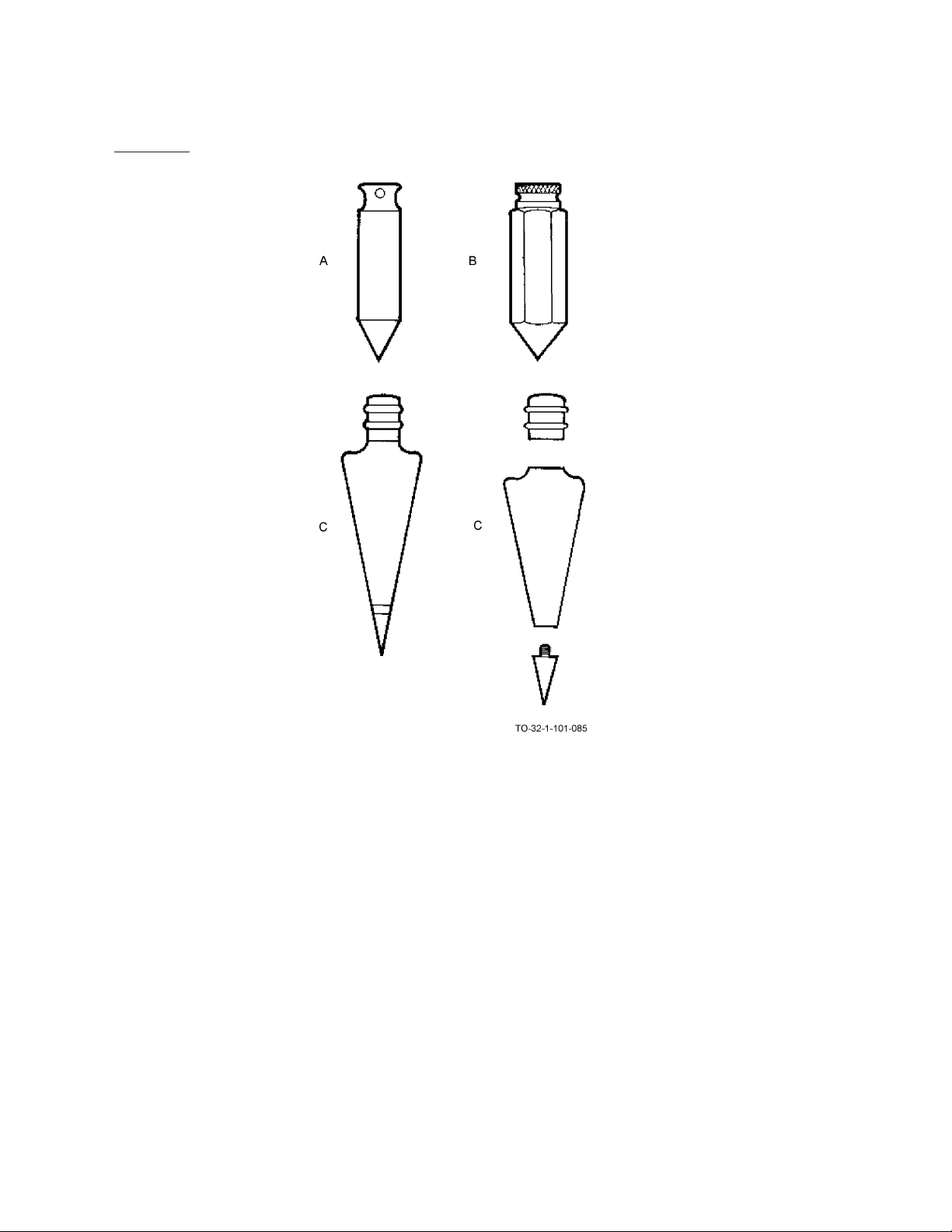
AIR FORCE AIR FORCE TO 32-1-101
ARMY ARMY TM 9-243
MARINE CORPS MARINE CORP TM 10209-10/1
NAVY (NAVAIR) NAVY M6290-AJ-MAN-1010
11.2.3 Solid Steel.
The solid steel plumb bob (A) may have a machined integral head, body, and point. It may have just a removable head
(B), or a removable head and a replaceable point (C). It may be round or hexagonagonal in shape and it comes in 3, 8,
and 12 ounce sizes. Cord for the solid steel bobs must be obtained from a separate source. This type plumb bob is used
when extreme accuracy is not required.
11-2

AIR FORCE AIR FORCE TO 32-1-101
MARINE CORPS MARINE CORP TM 10209-10/1
NAVY (NAVAIR) NAVY M6290-AJ-MAN-1010
11.3 USING A PLUMB BOB.
NOTE
The practice procedure which follows (for establishing the true vertical of a post) uses a plumb bob with a
removable head.
ARMY ARMY TM 9-243
The first step is to attach the cord as follows:
a. Insert a string or cord (1) into the cap (2) of the plumb bob. Make sure the cord will support the plumb bob. Pull the
cord through the cap.
11-3

AIR FORCE AIR FORCE TO 32-1-101
ARMY ARMY TM 9-243
MARINE CORPS MARINE CORP TM 10209-10/1
NAVY (NAVAIR) NAVY M6290-AJ-MAN-1010
b. Place cap in the palm of your hand and tie an overhand knot (3) in the cord. Pull the cord drawing the knot against cap
base. Make sure the knot is not too large or tied at an angle which would affect the hanging of the plumb bob.
c. Install cap into plumb bob body (4).
d. Tighten cap securely in the body and suspend the plumb bob by the cord only. Make sure the knot will support the
plumb bob.
11-4

AIR FORCE AIR FORCE TO 32-1-101
MARINE CORPS MARINE CORP TM 10209-10/1
NAVY (NAVAIR) NAVY M6290-AJ-MAN-1010
NOTE
• The following task is not the only use of a plumb bob.
• Post hole must be dug and an assistant is required before starting the task.
ARMY ARMY TM 9-243
e. Place a ruler (5) on the top of the post (6) so that it extends 2 inches beyond an edge.
11-5

AIR FORCE AIR FORCE TO 32-1-101
ARMY ARMY TM 9-243
MARINE CORPS MARINE CORP TM 10209-10/1
NAVY (NAVAIR) NAVY M6290-AJ-MAN-1010
f. Hang string and plumb bob so they extend over end of ruler and the plumb bob is just above the ground surface.
11-6
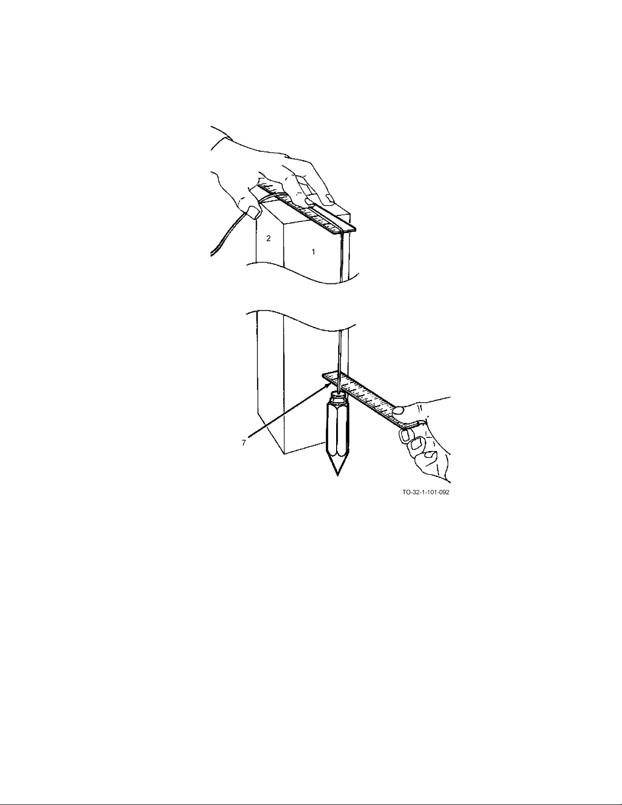
AIR FORCE AIR FORCE TO 32-1-101
MARINE CORPS MARINE CORP TM 10209-10/1
NAVY (NAVAIR) NAVY M6290-AJ-MAN-1010
g. Have the assistant measure distance (7) from post to string just above the plumb bob. It should read 2 inches. If it
doesn’t, move the base or the top of the post right or left until you get a 2 inch reading on both rules.
ARMY ARMY TM 9-243
11-7

AIR FORCE AIR FORCE TO 32-1-101
ARMY ARMY TM 9-243
MARINE CORPS MARINE CORP TM 10209-10/1
NAVY (NAVAIR) NAVY M6290-AJ-MAN-1010
When extreme accuracy is desired, measurement would be taken to the point of the plumb bob (8). Repeat Step e, Step f,
and Step g on side 2.
11-8

11.4 CARE OF PLUMB BOBS.
AIR FORCE AIR FORCE TO 32-1-101
ARMY ARMY TM 9-243
MARINE CORPS MARINE CORP TM 10209-10/1
NAVY (NAVAIR) NAVY M6290-AJ-MAN-1010
a. Handle plumb bobs with care. Do not use a plumb bob as a hammer or lever.As needed, lightly coat plumb bobs with
lubricating oil for short periods of storage. As needed for long-term storage, apply a heavy coat of oil and wrap the
plumb bob in oil-soaked paper.
b. Store plumb bobs in a protective box in a dry place. As needed, make certain threads of removable caps (1) and points
(2) are lightly coated with lubricant and placed in a protective box.
11-9/(11-10 blank)


AIR FORCE AIR FORCE TO 32-1-101
MARINE CORPS MARINE CORP TM 10209-10/1
NAVY (NAVAIR) NAVY M6290-AJ-MAN-1010
ARMY ARMY TM 9-243
CHAPTER 12
SCRIBERS
12.1 HOW TO CHOOSE AND USE SCRIBERS.
Types and Uses, Paragraph 12.2, provides you with a list of the types of scribers. These pages should help you select the
right scriber for the job. Using a Mechinist’s Scriber, Paragraph 12.3, tells you how to use the scriber to scribe an orientation
mark. Care of Scribers, Paragraph 12.4, tells you how to care for the scribers.
12.2 SCRIBERS TYPES AND USES.
12.2.1 Machinist’s Scribers.
The machinist’s scriber is used to mark or score on steel, glass, aluminum, copper or similar surfaces. There are two basic
types of machinist’s scribers, single point pocket (1), and bent point-straight point (2).
12-1

AIR FORCE AIR FORCE TO 32-1-101
ARMY ARMY TM 9-243
MARINE CORPS MARINE CORP TM 10209-10/1
NAVY (NAVAIR) NAVY M6290-AJ-MAN-1010
Tungsten carbide tips have extremely hard points and are used on hardened steel or glass.
The bent point is used to scribe through holes or other hard to reach places.
12.3 USING A MACHINIST’S SCRIBER.
NOTE
The following procedure for scribing an alignment mark on a telescope is not the only use of a scriber.
a. Place material to be marked on a firm surface. Place a steel rule or straight edge (1) on the work beside the line to be
scribed.
12-2
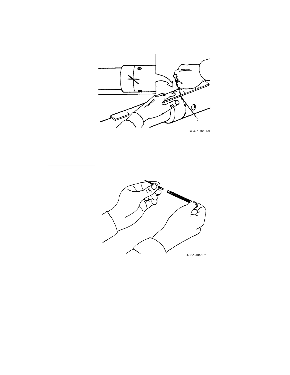
AIR FORCE AIR FORCE TO 32-1-101
MARINE CORPS MARINE CORP TM 10209-10/1
NAVY (NAVAIR) NAVY M6290-AJ-MAN-1010
b. Use finger tips of one hand to hold the straight edge securely. Hold the scriber in your hand as you would a pencil.
c. Scribe the line by drawing the scriber (2) along the straight edge at a 45 degree angle and tipped in the direction it is
being moved.
ARMY ARMY TM 9-243
12.4 CARE OF SCRIBERS.
12-3
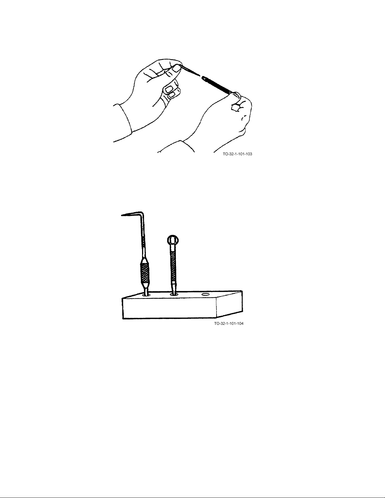
AIR FORCE AIR FORCE TO 32-1-101
ARMY ARMY TM 9-243
MARINE CORPS MARINE CORP TM 10209-10/1
NAVY (NAVAIR) NAVY M6290-AJ-MAN-1010
a. Protect points by reversing them in the handle or placing a cork or a piece of soft wood over point. (Optional if tool
is secured with foam inlay).
b. As needed, keep the scribers clean and lightly oiled.
c. Stow on a rack or in a box.
d. Do not use scribers for other than intended purposes.
12-4

AIR FORCE AIR FORCE TO 32-1-101
MARINE CORPS MARINE CORP TM 10209-10/1
NAVY (NAVAIR) NAVY M6290-AJ-MAN-1010
ARMY ARMY TM 9-243
CHAPTER 13
SQUARES
13.1 HOW TO CHOOSE AND USE SQUARES.
Types and Uses, Paragraph 13.2, provides you with a list of the types of squares. These pages should help you select the
right square for the job. Using Squares, Paragraph 13.3, tells you how to use a square to perform its various functions. Care
of Squares, Paragraph 13.8, tells you how to care for squares.
13-1

AIR FORCE AIR FORCE TO 32-1-101
ARMY ARMY TM 9-243
MARINE CORPS MARINE CORP TM 10209-10/1
NAVY (NAVAIR) NAVY M6290-AJ-MAN-1010
13.2 SQUARES TYPES AND USES.
13.2.1 Carpenter’s Square.
The carpenter’s square is made up of two parts: the body or blade, and the tongue. It has inches divided into eighths,
tenths, twelfths, and sixteenths. The face side contains the manufacturer’s name and the inches are divided into eighths
and sixteenths as shown. There are two tables down the center.
The rafter table is used for determining the length and cut of rafters.
The octagon or eight square scale is used for cutting an octagon from a square piece of material. The back side contains
13-2
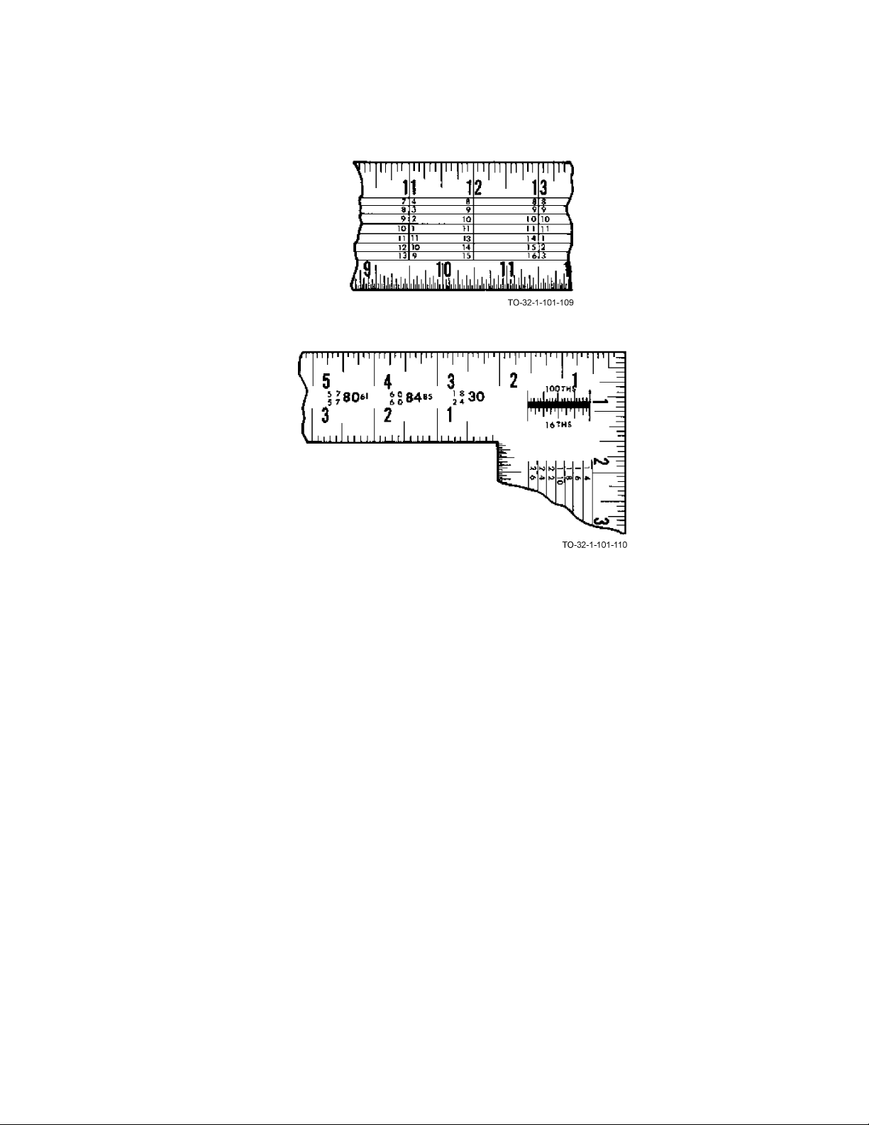
AIR FORCE AIR FORCE TO 32-1-101
MARINE CORPS MARINE CORP TM 10209-10/1
NAVY (NAVAIR) NAVY M6290-AJ-MAN-1010
the hundredths scale and is divided into tenths, twelfths, and sixteenths as shown. There are two tables down the center.
The essex board measure is used to compute the number of board feet in a given piece of lumber.
ARMY ARMY TM 9-243
The brace measure is used to find the exact lengths of common braces. The following scales or inch divisions are found
on the carpenter’s square:
Face of body outside edge inches and sixteenths
Face of body inside edge inches and eighths
Face of tongue outside edge inches and sixteenths
Face of tongue inside edge inches and eighths
Back of body outside edge inches and twelfths
Back of body inside edge inches and sixteenths
Back of tongue outside edge inches and twelfths
Back of tongue inside edge inches and tenths
13-3
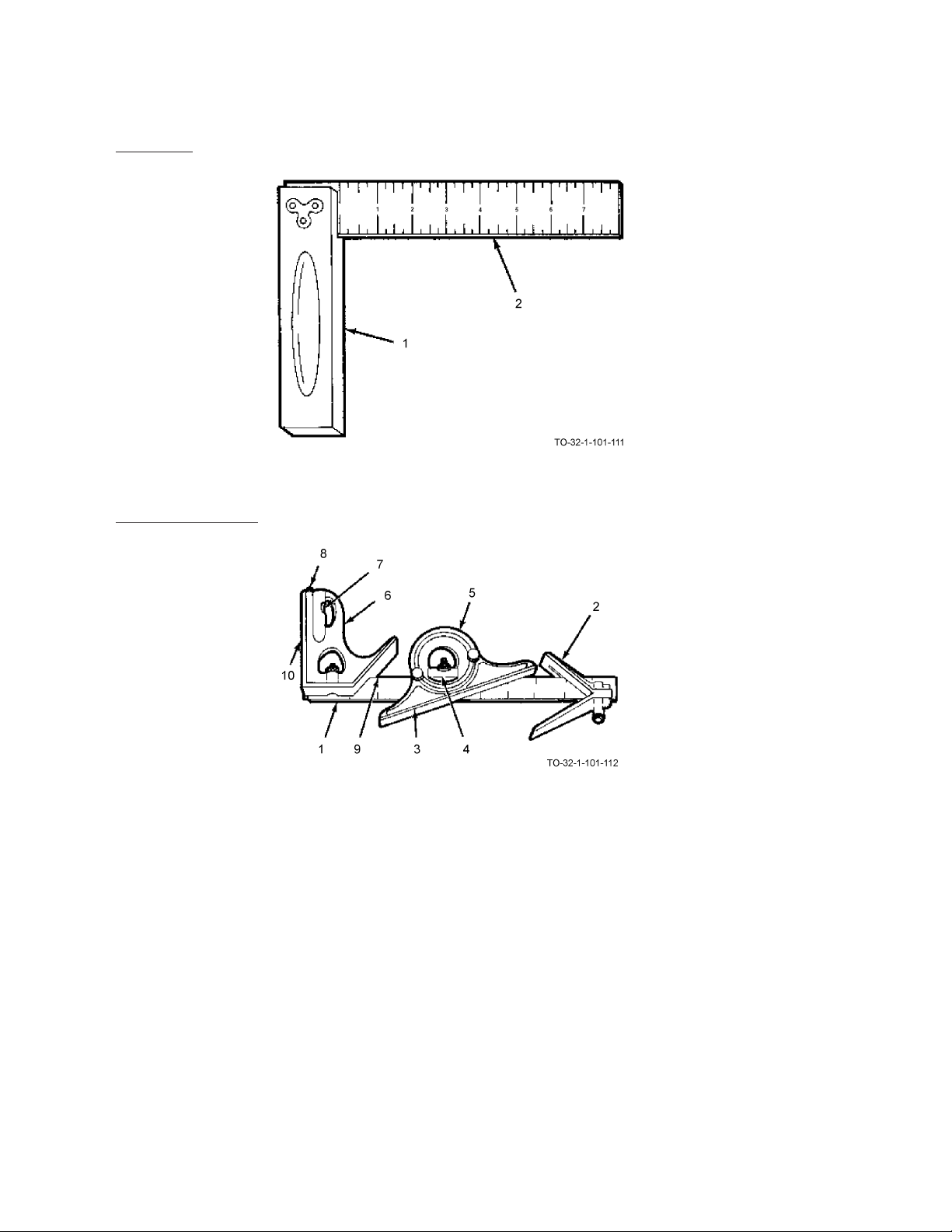
AIR FORCE AIR FORCE TO 32-1-101
ARMY ARMY TM 9-243
MARINE CORPS MARINE CORP TM 10209-10/1
NAVY (NAVAIR) NAVY M6290-AJ-MAN-1010
13.2.2 Try Square.
The try square is made of a steel or wood stock (1) and a blade (2). The blade is from 2 to 12 inches long and is graduated in eighths. The try square is used to set or check lines which are at right angles (90 degrees) to each other.
13.2.3 Combination Square.
The combination square is made up of the following components:
• A slotted 12 inch stainless steel rule (1) which is graduated in eighths, sixteenths, thirty-seconds and sixty-fourths of
an inch. It can be used as a measuring scale by itself or with any one of the following components.
• The center head (2), when attached to the rule, bisects a 90 degree angle. It’s used for determining the center of
cylindrical work.
• The protractor (3) has a level (4) and a revolving turret (5) which is graduated in degrees from 0 to 180 or 0 to 90
in either direction. It is used to lay out and measure angles to within one degree.
• The square head (6) has a level (7), a scribe (8), and 45 degree (9) and 90 degree sides (10). It is used to lay out 45
and 90 degree angles and to check level. It may also be used as a height or depth gage.
13-4

AIR FORCE AIR FORCE TO 32-1-101
MARINE CORPS MARINE CORP TM 10209-10/1
NAVY (NAVAIR) NAVY M6290-AJ-MAN-1010
13.2.4 Sliding T-Bevel.
The sliding T-bevel is made up of a slotted blade (1) and a solid stock (2). The blade is adjustable so it can be set to
measure any angle. The T-bevel is used for testing bevels and laying out angles.
13.2.5 Bevel Protractor.
ARMY ARMY TM 9-243
The bevel protractor is made up of an adjustable blade (1) and a graduated dial (2) which contains a vernier scale. The
bevel protractor is used to establish an angle and determine its relationship to other surfaces. The acute angle attachment
(3) is used for measuring acute angles accurately.
13.3 USING A CARPENTER’S SQUARE TO MARK A SQUARE LINE.
13-5
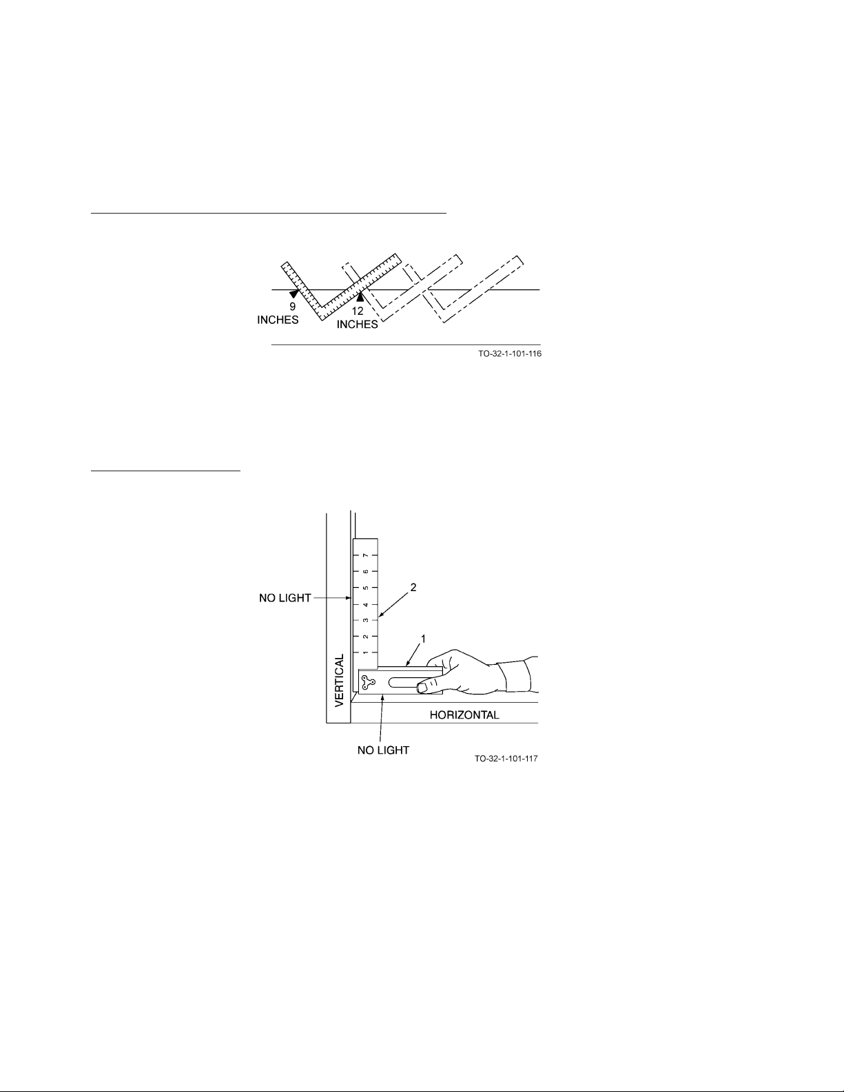
AIR FORCE AIR FORCE TO 32-1-101
ARMY ARMY TM 9-243
MARINE CORPS MARINE CORP TM 10209-10/1
NAVY (NAVAIR) NAVY M6290-AJ-MAN-1010
a. To mark a square line, place the blade or tongue (1) of the square against the side of the material with the square tilted
slightly so the blade or tongue of the square extends across the work.
b. Mark a line across the work using a pencil or marking crayon.
13.4 USING A CARPENTER’S SQUARE TO LAY OUT STEPS.
a. The preceding example shows proper square position when marking cut lines for a series of steps 9 inches x 12 inches.
b. Continue the process until desired number of steps has been laid out.
13.5 USING A TRY SQUARE.
13-6

AIR FORCE AIR FORCE TO 32-1-101
MARINE CORPS MARINE CORP TM 10209-10/1
NAVY (NAVAIR) NAVY M6290-AJ-MAN-1010
a. To check a square joint, place the stock (1) against a horizontal section and the blade (2) against a vertical section.
Light must not be seen around blade edge. If light is seen, the work is not square.
b. To check the end of a board, place stock on vertical edge and extend blade over the end. Light must not be seen around
blade edge. If light is seen, the work is not square.
ARMY ARMY TM 9-243
13.6 USING A SLIDING T-BEVEL SQUARE.
13-7

AIR FORCE AIR FORCE TO 32-1-101
ARMY ARMY TM 9-243
MARINE CORPS MARINE CORP TM 10209-10/1
NAVY (NAVAIR) NAVY M6290-AJ-MAN-1010
a. Loosen locking nut (1) and adjust blade (2) to measure a desired angle using protractor (3). Tighten locking nut (1).
b. The angle may now be laid out by extending the blade across the board with the stock (4) held firmly against the edge.
c. Mark with a pencil or marking crayon. Make sure the square does not move while marking.
13.7 USING A COMBINATION SQUARE.
13.7.1 Using as a Center Head to Find the Diameter of a Cylinder.
13-8

MARINE CORPS MARINE CORP TM 10209-10/1
NAVY (NAVAIR) NAVY M6290-AJ-MAN-1010
a. Slide center head (1) on rule (2) and fasten by tightening setscrew (3).
b. Put the center head flush against the cylinder.
AIR FORCE AIR FORCE TO 32-1-101
ARMY ARMY TM 9-243
c. Mark the diameter on the cylinder using a pencil or marking crayon by drawing a straight line along the inside edge
(4). Make sure the square does not slip while marking.
13.7.2 Using as a Protractor Head to Determine an Angle.
13-9

AIR FORCE AIR FORCE TO 32-1-101
ARMY ARMY TM 9-243
MARINE CORPS MARINE CORP TM 10209-10/1
NAVY (NAVAIR) NAVY M6290-AJ-MAN-1010
a. Slide protractor head (1) on rule (2) and fasten by tightening setscrew (3).
b. Loosen the protractor adjustment screws (4) so the protractor may be pivoted about the rule. Angle being measured is
already marked.
c. Place the rule on the angle being measured and pivot the protractor head against the edge. Tighten adjustment screws.
d. Remove and read measured angle on protractor scale.
13-10

MARINE CORPS MARINE CORP TM 10209-10/1
13.7.3 Using a Combination Square to Determine Depth.
a. Slide square head (1) on rule (2) and fasten by tightening setscrew (3).
b. Loosen setscrew.
AIR FORCE AIR FORCE TO 32-1-101
ARMY ARMY TM 9-243
NAVY (NAVAIR) NAVY M6290-AJ-MAN-1010
13-11
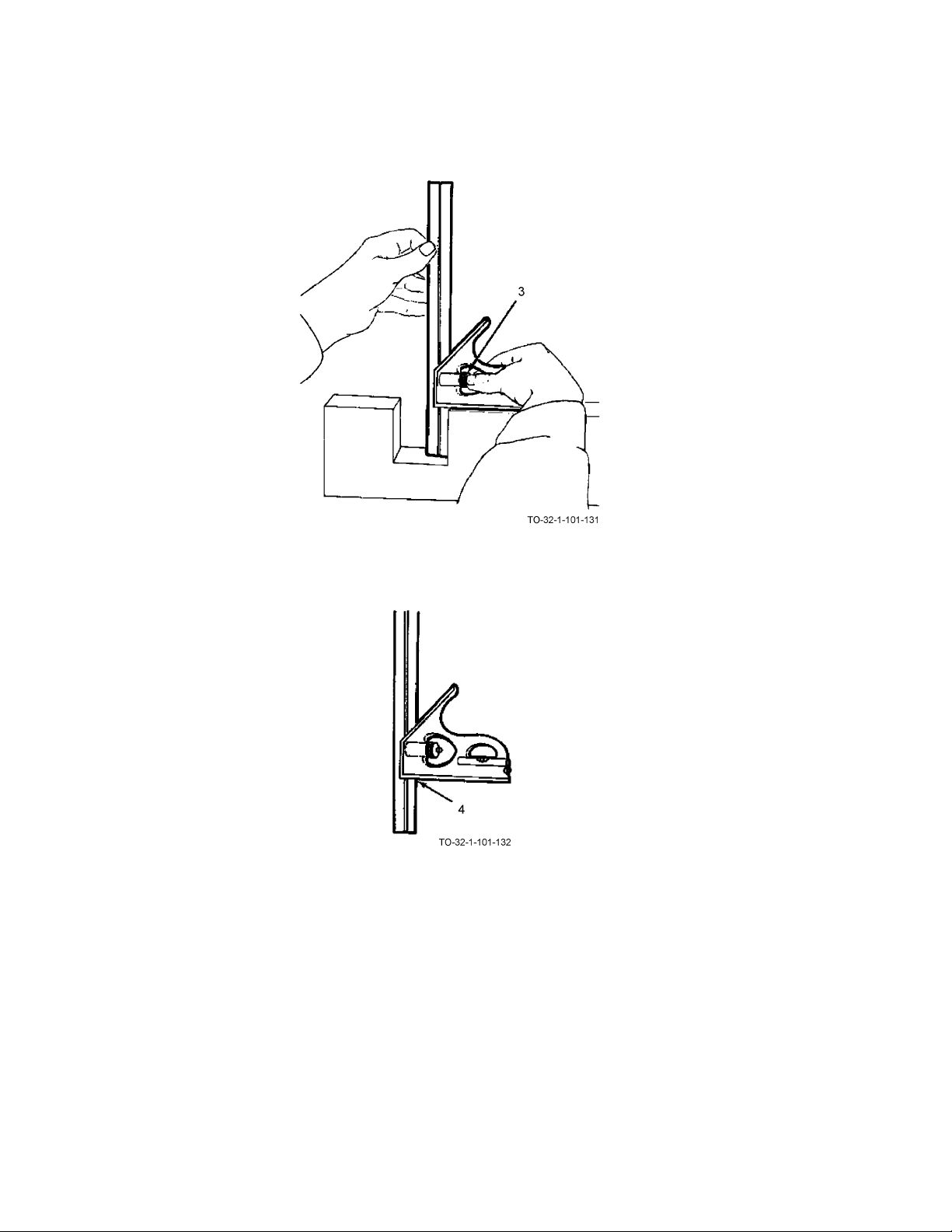
AIR FORCE AIR FORCE TO 32-1-101
ARMY ARMY TM 9-243
MARINE CORPS MARINE CORP TM 10209-10/1
NAVY (NAVAIR) NAVY M6290-AJ-MAN-1010
c. Set the flat surface of the square head (1) above the hole and adjust the rule (2) until it hits the bottom.
d. Tighten setscrew (3).
e. Remove the combination square and read the depth at the intersection of the rule and the square head (4).
13-12
 Loading...