

Page 1

The VMARS Newsletter Issue 12
THE SEM-35 MANPACK
by Murray McCabe
Introduction
The West German SEM-35 VHF FM manpack
radio is available from various UK and EU
dealers. This note gives a brief description of the
set, its historical relevance, circuit and
performance. The SEM-35 performance and
characteristics are given in Table 1.
Table 1: SEM-35 Specifications
Frequency
Coverage
Channels 880 spaced 50kHz
Modulation F3 (FM)
Deviation 15kHz max.
Transmitter RF
Output
Frequency
Stability
Receiver
Sensitivity
Receiver
Selectivity
AF bandwidth 400 to 3000Hz
Receiver AF
Output
Receiver
Squelch
Weight Approx. 13kg
Antennae 1m nom. tape whip (“short”)
Power Supply 24 Volt DC external (21 to 29V,
Overall Size 359x270x125 mm
Historical
Military radios do not just pop into existence.
Most result from a steady, progressive
improvement to existing designs. Some,
however, are landmark designs that made a major
step forward. These resulted from a
comprehensive, innovative, well financed and
thought out development that appraised all
aspects of a radio including the man-to-set
interface.
26 to 69.95MHz
150 mW or 1Watt
< + 3.5kHz from -40 to +600C
< 0.5 micro volts for 10db
reduction in S/N
> 80db at + 50kHz
50mW into 600 ohm or 600 ohm
earth free line output
Switched
2.5m self erecting whip (“long”)
SEM-25 remote antenna
32V transient max.)
or
Internal 12 off U2 cells - normal
or NiCd
In the case of VHF FM synthesised military radios
the ground breaking design work was conducted in
the US in the 1950s and early 1960s. This was by
force of circumstance because, especially in the
early 1950s, only the US had the finance,
resources and volume requirements to undertake
and justify the work.
The 'landmark' sets that resulted were the RCA
PRC-25 VHF FM backpack radio and the AVCO
VRC-12 VHF FM vehicle set. Both sets covered
30 to 76 MHz and both employed transistors. The
PRC-25 retained one valve in its transmitter RF
output. The fully transistorised PRC-25 was later
issued as the PRC-77.
It was the arrival of the transistor that allowed the
complexities of the synthesiser to be engineered
for field use with acceptable physical size,
performance and power supply requirements.
The US evolved a circuit configuration for military,
synthesised VHF FM transmitter receivers that
was almost as significant, in its field, as the
development of the superhet. It consisted of a two
band receiver, synthesised in 50kHz steps by a
single band local oscillator. On the receiver low
band (30 to 52.95MHz) the received frequency
was local oscillator frequency minus intermediate
frequency (IF). On the high band (53 to
75.95MHz) local oscillator plus IF frequency. The
receiver first IF was 11.5MHz and each receiver
band was twice IF frequency wide, i.e. 2 x 11.5 =
23 MHz.
The use of a single band local oscillator simplified
band switching, reduced component count and
provided two working RF frequencies for each
synthesised local oscillator frequency.
The transmitter frequency of the US radios was
locked to the synthesiser frequency by the use of
a crystal controlled 11.5MHz 'side step' oscillator
that beat with the synthesiser output frequency to
generate the transmitter frequency. This
synthesiser configuration became the basis for
subsequent VHF FM military radio designs.
The VRC-12 and PRC-25 were quite different
radios, because, internally and externally each
had been optimised for its duty as a vehicle and a
manpack set respectively. The PRC-25 replaced
the three valve sets of the PRC-10A series. The
most important aspects of its design were its
ruggedness, reliability and the basic simplicity of
its controls. It was not a prima ballerina requiring
excessive workshop attention and, in an
emergency, anyone could pick it up and use it
without previous training. The PRC-25 was
introduced to US service in small quantity in 1961
11 August 2000
Page 2
The VMARS Newsletter Issue 12
but it was nearly 4 years later before
it entered volume production (Ref.1).
SEM 35 Development
West Germany had used the US
designed PRC-10 series radios. By
the early 1960s they had a
requirement for synthesised sets to
update army VHF FM field
communications. Their home
electronics industry was by then reestablished after the war. They
decided to develop the synthesised
sets themselves as a first foray in the
field.
The receiver synthesiser format
would be based on the US work but
lacking the US's budget, the manpack and vehicle
sets would be developed in a single programme.
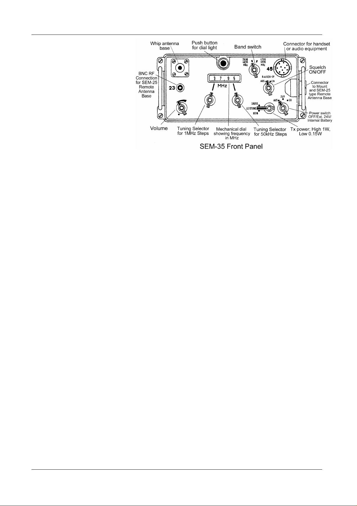
SEM-35 Detail
The SEM-35 covers the early European tactical
spectrum of 26.00 to 69.95MHz rather than the US
The transmitter would employ a simpler automatic
frequency loop similar from that used for earlier
VHF FM radios such as the PRC-10. It would use
an 11.5MHz discriminator before the receiver IF
filter to regulate the transmitter oscillator at
11.5MHz from the receiver synthesiser frequency.
This would replace the PRC-25 side step crystal
oscillator. It would be less accurate than the PRC25 arrangement since it would rely on the tuning
of a discriminator rather than an 11.5MHz crystal.
However, the SEM-35 circuit achieved an
acceptable transmitter frequency accuracy of
better than + 3.5kHz from -40 to +60oC.
The German contract was awarded to Standard
Elektrik Lorrenz AG of Stuttgart. The end result
was the SEM-35 manpack, the SEM-25 vehicle
transceiver and the EM-25 vehicle receiver. The
EM-25 receiver is basically the SEM-25 hardware
in a SEM-25 case with the internal transmitter
sections omitted. The EM-25 is, therefore,
externally similar to, and easily confused with, the
30 to 76MHz spectrum of the PRC-25 and VRC-
12. The set provides a total of 880 channels
spaced by 50kHz. These are covered in two
frequency bands. A high band from 47 to 69.95
MHz and a low band from 26 to 46.95 MHz. The
SEM-35 has the same 11.5MHz receiver first IF
as the PRC-25 and each band could be 23MHz
wide permitting a low band of 24 to 46.95MHz.
The SEM-35 receiver can operate down to 24
MHz but the transmitter is automatically disabled
below 26 MHz. The tuning display is a
mechanical counter dial giving direct read out of
frequency. The tuning arrangement does not
permit two channels to be pre-set as on the PRC-
25.
The transmitter output power can be switched for
150mW or 1Watt RF output. The receiver
sensitivity is better than or equal to 0.5microvolts
for 10db signal-to-noise. Squelch is pre-set and
selected by switch but it is not the US 150Hz tone
squelch.
SEM-25. The sets entered service in the late
1960s.
A battery box toggle clamps below the set and
contains a holder for 12 off U2 cells, either normal
The SEM-35 was primarily intended as a manpack
but a vehicle mounting and a rebroadcast/relay
adapter were produced for it and it could use the
SEM-25 remotely tuned aerial base. These
allowed the SEM 35 to fulfil vehicle, ground static
and re-broadcast/relay roles.
All three sets share two common large-circuit
modules with obvious advantages in spares
holding and maintenance.
However, the requirement that one programme
develop both a manpack and a vehicle set
produced conflicting goals. As a result, the SEM35 has features and components more appropriate
to a vehicle radio. In this respect the most
obvious vehicle type component is a large multigang permeability tuner reminiscent of the
techniques employed in the auto radios of the day.
BA 30 or rechargeable Ni.Cd. cells. On a 9:1
Rx:Tx ratio the BA 30 cells give a 14 hour life
while the NiCd cells give 20 hours per charge.
Battery exhaustion, i.e. the minimum battery
voltage for operation is quoted as 13.2V. The
battery box also contains a transistor inverter
producing supplies of +6V, +16V, -17V and -30V
DC from the internal battery or from a 24Volt
external source.
The set uses a 1m laminated tape aerial and a
2.5m self-erecting whip like the PRC-25 but unlike
the US PRC ancillaries each whip has a tapped
cup at its base that screws over a stud type
antenna mount on the set front panel. The set
stud base has a sprung piston at its centre which,
when depressed, operates switches to select the
appropriate antenna matching circuits.
August 2000 12
Page 3
The VMARS Newsletter Issue 12
With no whip fitted the set RF output is switched
to the 50 ohm BNC socket for connection to the
remote antenna base. The cup on the bottom of
the 1m tape antenna fully depresses the plunger
while the cup on the bottom of the 2.5m whip only
depresses the plunger by about 50% of its travel.
A similar antenna base is used on the West
German SE-6861 SSB manpack radio.
The set employs transistors throughout but
because of its design age the transistors are a mix
of PNP, NPN, germanium and silicon types.
Circuit Description
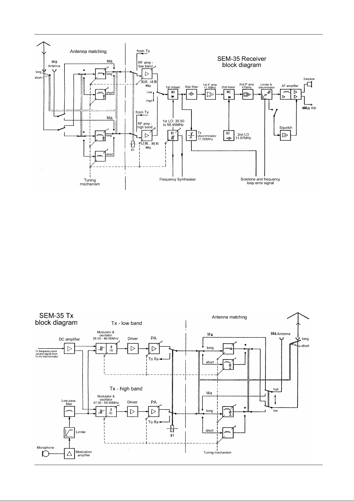
Each receiver band has a separate RF amplifier
(to simplify band switching). These amplifiers are
single germanium PNP AFZ12, TO18 transistors,
in a grounded base configuration with diode
clamps to prevent RF burn-out. There are 2
permeability tuned LC circuits in front of each RF
amplifier and one between it and the receiver first
mixer.
The first mixer is a diode ring of 4 x OA90
germanium diodes with 50 ohm ports, mounted on
a small, unscreened printed circuit board (PCB).
The receiver first IF is 11.5 MHz with a 30 kHz
bandwidth crystal filter. The first receiver local
oscillator covers 35.50 to 58.45 MHz in one band.
The second receiver mixer is a transistor with a
crystal controlled 11.97 MHz local oscillator. The
second IF and limiter frequency is 470 kHz. This is
followed by a discriminator, an AF pre-amp with
low pass filter (LPF) and a push pull Class B audio
13 August 2000
Page 4

The VMARS Newsletter Issue 12
output stage. Unusually, the volume control is
between the AF output transformer and the
handset. The handset is an H-33*/PT as used on
the PRC-10 series, complete with a U-77/U
connector.
The squelch circuit has a relay output.
The receiver first local oscillator is frequency
stabilised by the synthesiser. A signal from the
receiver local oscillator goes via a buffer amplifier
to the first mixer of the synthesiser. The local
oscillator signal for this mixer is generated from a
1 MHz crystal oscillator. The 1 MHz oscillator
output is clipped and shaped to make it rich in
harmonics and then passed through an LPF to the
mixer. The LPF lets through the 1 MHz
harmonics from 1 to 11 MHz but attenuates the
higher harmonics to ensure that they do not
appear in the receiver tuning range.
The synthesiser first IF is a bandpass amplifier
from 46.50 to 47.45 MHz. Only one of the 1 MHz
harmonics can beat with the receiver local
oscillator to produce a signal in the first
synthesiser IF. As with the receiver local
oscillator, the 1 to 11 MHz (0 to 11 MHz) beats
with the receiver local oscillator on a sum and
difference basis to cover the full 22.95 (23) MHz
single band tuning.
The local oscillator for the second synthesiser
mixer is an overtone crystal oscillator with one of
two frequencies spaced by 0.500MHz, i.e. 33.425
or 33.925 MHz. The overtone oscillator frequency
is remotely selected from switches on the 50 kHz
tuning selector via decoupled control lines that
enable the appropriate oscillator output. The two
frequencies are used for alternate bands of
0.500MHz, e.g. one for receiver tuning from 26.00
to 26.45 MHz, the other from 26.5 to 26.95 MHz,
then back to the first from 27.00 to 27.45 and so
on. Both overtone frequencies are midway
between receiver channels and are attenuated by
the receiver IF crystal filter should they leak into
the receiver RF input circuits.
The second synthesiser IF is a bandpass amplifier
from 13.075 to 13.525 MHz. The local oscillator
for the third synthesiser mixer is controlled by one
of 10 crystals spaced by 50kHz from 14.525 to
14.575 MHz. These are ganged to, and selected
by, the 50 kHz channel selector switch. In
combination with the switched overtone oscillator
for the second synthesiser mixer they provide the
20 off 50 kHz channels per MHz, i.e. the first 10
channels on one overtone oscillator then a further
10 on the second overtone oscillator.
The IF output of the third mixer is 1.45 MHz. This
feeds two discriminators, a wideband discriminator
to capture the signal initially and a narrow band
crystal discriminator for the final frequency lock.
The discriminator outputs feed a varactor diode in
the receiver local oscillator to complete the
synthesiser loop.
Table 2 shows typical synthesiser internal
frequencies for the SEM-35 tuned to 26.5MHz.
Table 2: synthesiser frequencies
Circuit point MHz
SEM-35 tuned to 26.500 A
Receiver first IF 11.500 B
Receiver first local oscillator. 38.000 C = A + B
9th Harmonic of 1MHz oscill. 9.000 D
Synthesiser first IF 47.000 E = C + D
Overtone oscillator No.2 33.925 F
Synthesiser second IF signal 13.075 G = E - F
First crystal in decade 14.525 H
Synthesiser third IF signal 1.450 I = H - G
As with the receiver RF amplifiers, there are two
transmitter RF sections. One High band and one
Low band. A sample of the transmitter output
feeds the appropriate receiver RF amplifier,
passes through the receiver first mixer to an 11.5
MHz discriminator at the input to the crystal filter.
The discriminator output feeds a varactor diode in
the TX oscillator to lock the transmitter frequency
to the receiver local oscillator. The two transmitter
RF sections share a common microphone
processing circuit consisting of a pre amplifier, an
AF clipper/limiter and an LPF.
Groans and Whinges
The SEM-35 suffers from having shared a
common development programme with the SEM25 vehicle radio. For vehicle duty there is ample
power available from the vehicle battery and the
designer can be lax about designing for energy
efficiency. This mindset carried over into the
SEM-35.
The PRC-10 series valve sets that preceded the
SEM-35 required a total battery power of 8.4watts
in transmit to generate a nominal 1watt RF output.
The SEM-35 requires 10watts of battery power to
generate a similar RF output. On the receiver
front the position is better but still not good. On
receive the PRC-10 drew 2.6watts while the SEM35 draws 2watts.
Because of the lack of valve filaments and HT
supplies most transistor versions of valve sets
should require about 20% of the valve set power.
It goes against logic that a transistor transmitter
should require a larger power supply than its valve
equivalent for the same power output.
Where does the power go? The power supply
inverter is not nearly as efficient as it could be.
The French BA-511-A is a good example of what
could be achieved by the late 1960s and the SEM-
August 2000 14
Page 5

The VMARS Newsletter Issue 12
35 inverter falls far short of this in efficiency, size
and weight. The SEM-35 has too many supply
rails with too many dropper resistors. Unusually
for a manpack it uses 6 relays. All these features
are perfectly acceptable for vehicle sets but for
portable sets they represent substantial life costs
for battery procurement and re-supply and/or
additional portage weight. It was within the
technology of the day to double or triple the
battery life and similarly reduce battery re-supply
costs. This could have given significant payback
over the operational life of the set.
On the receiver of the SEM-35 example examined
the local VHF broadcast stations 'broke through' at
frequencies around 30MHz. For example the
local music station on 89.9MHz was picked up
when the SEM-35 was tuned to 27.7MHz. At that
frequency the SEM local oscillator was 39.2MHz
and its second harmonic 78.4MHz. The 78.4MHz
beat with the 89.9MHz station to produce the
11.5MHz first IF frequency of the SEM-35.
When the SEM-35 was developed there would not
have been the current profusion of VHF FM
entertainment stations and the breakthrough
would not have been as obvious.
The strength of the break through varied with hand
proximity to the SEM control knobs. Further
investigation showed that the control knobs, shafts
and bushes were not making contact with the set
front panel. There were star washers under their
shaft bush nuts that should have scraped through
paint and earthed the controls but the quality of
painting (thought to be powder spray epoxy) had
been too hard and durable to allow the star
washers to cut through.
The paint was scraped away in the spot faces for
the washers, the nuts and washers were replaced
and hand sensitivity was reduced. The
breakthrough continued but it was not coming
from the aerial base or BNC connector but from
the battery box and leads. The battery leads are
decoupled to the inverter chassis in the battery
box. There was, however, poor electrical contact
between the battery box and the set case.
Consequently, an earth to the battery box is not a
good signal earth for the receiver. A general
clean-up of the contact faces between the battery
box and the set plus a check with a low resistance
ohmmeter did not remove the problem. The
designers had effectively RF decoupled the front
panel audio and control connectors but had left
the back door open by not decoupling the leads
from the battery box to the set RF earth.
Leads from the battery box to the set ON/OFF
switch loop up into the set passing close to the
unscreened first receiver diode ring mixer.
Decoupling these leads as they enter the base of
the SEM-35 with small 10nF ceramic capacitors
cured the RF break through and appeared to
marginally improve overall performance. It was
as if the battery box had been acting as a
wideband aerial passing general noise directly to
the mixer, bypassing the selectivity of the set RF
amplifier.
With its web rucksack, antennae and the Ni.Cd
battery the SEM-35 has a portage weight of
approximately 12.8kg. This is heavier than the
PRC-10 and the PRC-25.
Other than its tuning controls, the PRC-25 has two
panel controls. ON/OFF and VOLUME. The
SEM-35 has four. This is no great hassle but it
indicates that the benefits from rigorous
simplification of controls have not been realised
on the SEM-35.
The SEM 35 is built with precision and with
components of quality. Wiring, PCB design and
construction are good but it is as if the designers
lacked experience in the specific field of military
manpack radios. Consequently, the SEM-35 was
not the step forward from the PRC-25 that it could
have been.
Equipment and Data
SEM-35 manuals in German are available from
http://www.algra-funkarchiv.de and
http://www.milradio.com/
At the time of writing the SEM-35 rucksack and
2.5m antenna are advertised by
http://www.helmut-singer.de
References
Reference 1 - The PRC-25 Legend”,
http://www.telalink.net/~badger/millist/prc25legend
.html
15 August 2000
 Loading...