

Milestone pro MP-SC-12D-TN User Manual
MP-SC-12D-TN
Scaler Switcher with Digital Amplifier-TN
(12 Inputs)
All Rights Reserved
Version: MP-SC-12D-TN_2016V1.0
User Manual

Scaler Switcher with Digital Amplifier-TN
Preface
Read this user manual carefully before using this product. Pictures shown in this manual
is for reference only, different model and specifications are subject to real product.
This manual is only for operation instruction only, not for any maintenance usage.
Trademarks
Product model and logo mentioned in this manual are trademarks of our company. Any
other trademarks mentioned in this manual are acknowledged as the properties of the
trademark owner. No part of this publication may be copied or reproduced without prior
written consent.
FCC Statement
This equipment generates, uses and can radiate radio frequency energy and, if not
installed and used in accordance with the instructions, may cause harmful interference
to radio communications. It has been tested and found to comply with the limits for a
Class B digital device, pursuant to part 15 of the FCC Rules. These limits are designed
to provide reasonable protection against harmful interference in a commercial
installation.
Operation of this equipment in a residential area is likely to cause interference, in which
case the user at their own expense will be required to take whatever measures may be
necessary to correct the interference.
Any changes or modifications not expressly approved by the manufacture would void
the user’s authority to operate the equipment.

Scaler Switcher with Digital Amplifier-TN
SAFETY PRECAUTIONS
To insure the best from the product, please read all instructions carefully before using
the device. Save this manual for further reference.
Unpack the equipment carefully and save the original box and packing material for
possible future shipment
Follow basic safety precautions to reduce the risk of fire, electrical shock and injury
to persons.
Do not dismantle the housing or modify the module. It may result in electrical shock
or burn.
Using supplies or parts not meeting the products’ specifications may cause damage,
deterioration or malfunction.
Refer all servicing to qualified service personnel.
To prevent fire or shock hazard, do not expose the unit to rain, moisture or install this
product near water.
Do not put any heavy items on the extension cable in case of extrusion.
Do not remove the housing of the device as opening or removing housing may
expose you to dangerous voltage or other hazards.
Install the device in a place with fine ventilation to avoid damage caused by
overheat.
Keep the module away from liquids.
Spillage into the housing may result in fire, electrical shock, or equipment damage. If
an object or liquid falls or spills on to the housing, unplug the module immediately.
Do not twist or pull by force ends of the optical cable. It can cause malfunction.
Do not use liquid or aerosol cleaners to clean this unit. Always unplug the power to
the device before cleaning.
Unplug the power cord when left unused for a long period of time.
Information on disposal for scrapped devices: do not burn or mix with general
household waste, please treat them as normal electrical wastes.

Scaler Switcher with Digital Amplifier-TN
Contents
1. Introduction ................................................................................................................. 1
1.1. Introduction to MP-SC-12D-TN ......................................................................... 1
1.2. Features ........................................................................................................... 1
1.3. Package Contents ............................................................................................ 1
2. Panel Description ........................................................................................................ 2
2.1. Front Panel ................................................................................................ ....... 2
2.2. Rear Panel ........................................................................................................ 2
3. System Connection ................................ ................................ ................................ ..... 3
3.1. Usage Precautions ........................................................................................... 3
3.2. System Diagram ............................................................................................... 3
3.3. Connection Procedures .................................................................................... 4
3.4. PoC Solution ..................................................................................................... 5
3.5. Applications ...................................................................................................... 6
3.6. Collocation Products ......................................................................................... 6
4. Operations .................................................................................................................. 7
4.1. Operations of the IR Remote ............................................................................ 7
4.2. OSD Operations ................................ ................................ ............................... 8
4.2.1. Picture Setting ........................................................................................ 8
4.2.2. Audio Setting .......................................................................................... 9
4.2.3. System Setting ..................................................................................... 10
4.3. Firmware Update ............................................................................................ 10
4.4. RS232 Control ................................................................................................ 11
4.4.1. Installation/uninstallation of RS232 Control Software ........................... 11
4.4.2. Basic Settings ....................................................................................... 11
4.4.3. RS232 Commands ................................ ............................................... 12
4.4.4. Control Modes ...................................................................................... 15
4.4.5. Control MP-SC-12D-TN via TCP/IP communication software .............. 16
4.4.6. TCP/IP Configuration ............................................................................ 17
5. Specification ............................................................................................................. 18
5.1. Specifications of MP-SC-12D-TN ................................................................... 18
5.2. Specifications of Video/Audio Input/output ..................................................... 19
5.2.1. C-Video and S-Video input ................................................................... 19
5.2.2. YPbPr input .......................................................................................... 20
5.2.3. VGA input ............................................................................................. 20
5.2.4. HDMI input ............................................................................................ 20
5.3. Audio input/output ................................................................ ........................... 21

Scaler Switcher with Digital Amplifier-TN
6. Panel Drawing .......................................................................................................... 21
7. Troubleshooting & Maintenance ............................................................................... 22
8. After-sales Service .................................................................................................... 23

Scaler Switcher with Digital Amplifier-TN
1
1. Introduction
1.1. Introduction to MP-SC-12D-TN
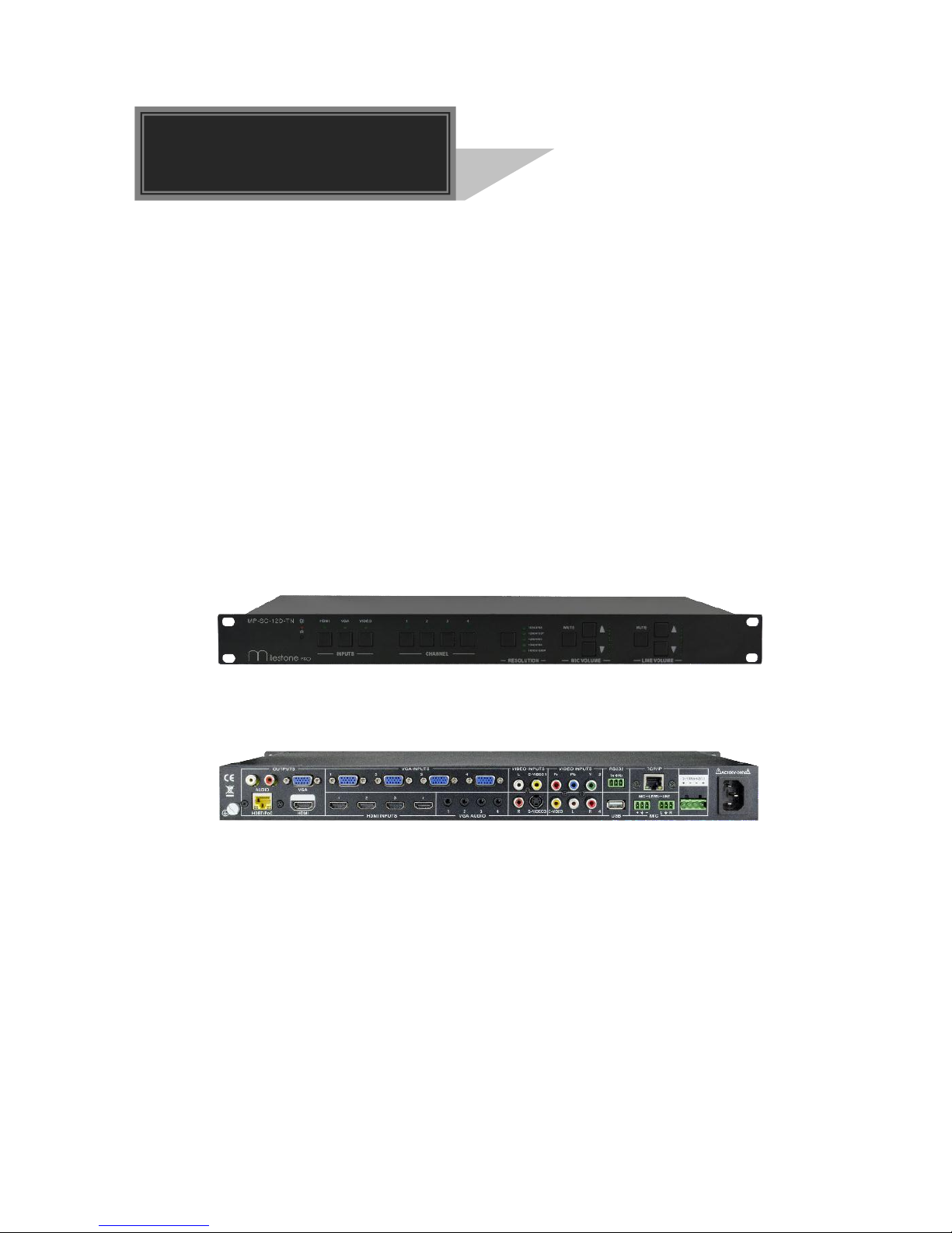
MP-SC-12D-TN is a full HD scaler switcher with 12 video, 6 audio & 2 MIC inputs. It
scales & switches any video signal HDMI, VGA, YPbPr, C-Video & S-video to HDBaseT,
HDMI & VGA simultaneously, and any audio to 2x20W amplifier. It’s controllable via the
button, IR, RS232 & TCP/IP.
It’s a remarkable scaler for education institution, meeting room, conference room,
demonstration hall etc. with its excellent performance.
1.2. Features
12 video Inputs: 4 HDMI, 4 VGA, 1 YPbPr, 2 C-video & 1 S-video.
2 MIC inputs with level control and mixer function.
Upscale to outputs HDBaseT, HDMI & VGA simultaneously up to 1080P.
HDBaseT output to be paired with HDMI/IR/RS232 Twisted Pair PoC receiver for
60M transmission.
Built-in 2x20Watt@4Ω digital amplifier (or 2x10Watt@8Ω).
Output resolution selectable to assure preferred output.
Output display H/V size: adjustable to settle any overscale problem.
Output display H/V position moveable.
MIC volume and line volume adjustable.
Video parameter setting and preset.
Powerful OSD function with full control.
Ultra-switching for instaneous display.
HDMI1.3 and HDCP compliant.
Firmware updatable via USB.
Output freeze function.
Energize PoC receiver with PoC function
Front panel lockout.
Controllable via HDMI/IR/RS232 Twisted Pair PoC receiver at display end.
Controllable via button, IR, RS232 & TCP/IP.
1.3. Package Contents
1 x MP-SC-12D-TN
1 x HDBT Receiver (not included in package contents of MP-SC-12D, MP-SC-12D
-N)
2 x Mounting Ears (for HDBT Receiver)
4 x Screws
3 x Captive Screw Connectors
1 x RS232 cable
4 x Plastic cushions
1 x IR remote (Cell battery is not included)
1 x Power Cord
Scaler Switcher with Digital Amplifier-TN
2
1 x User Manual
Notes:Please confirm if the product and the accessories are all included, if not, please
contact with the dealers.
2. Panel Description
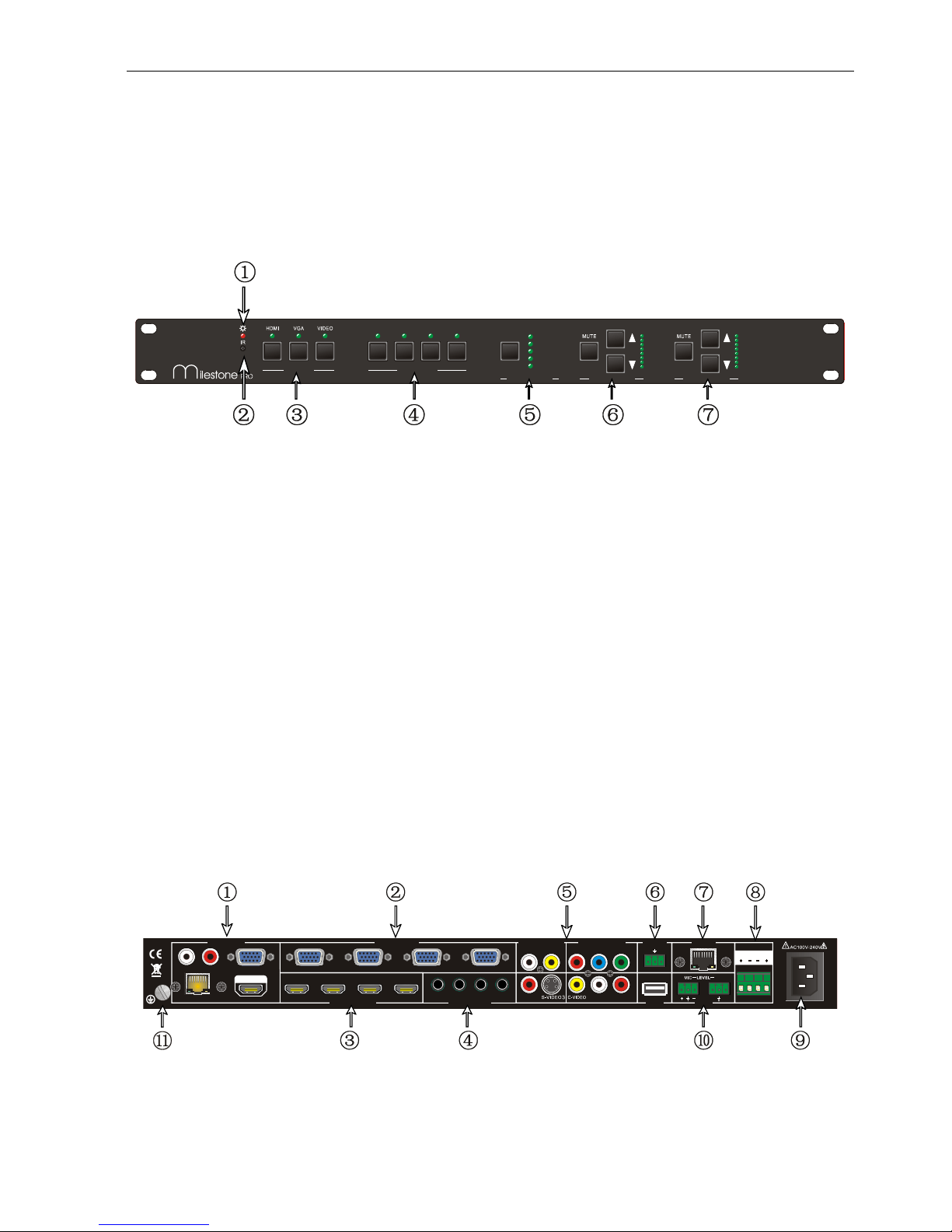
2.1. Front Panel
① Power indicating LED. It will illuminate red when the unit is connected with power.
② IR sensor, receive signals sent from of IR remote.
③ Video source selection buttons. You can select video/audio sources by pressing
these buttons. And VIDEO source includes three different signals: YPbPr, C-Video
and S-Video.
④ Signal channel selection buttons, 4 in total, correspond to the 4 input sources
separately.
⑤ Resolution selection buttons. These including 1024×768, 1280x720p, 1280×800,
1360×768, 1920×1080p.
⑥ MIC volume control buttons. “MUTE” for mute MIC volume, “△”for MIC volume up,
“▽”for MIC volume down, loop controlling.
⑦ Line volume control buttons. “MUTE” for muting line volume, “△”for line volume up,
“▽”for line volume down.
Note: Pictures shown in this manual are for reference only, different model and
specifications are subject to real product.
2.2. Rear Panel
① Two RCA connectors for stereo audio output;
One VGA output;
1 2
3
4
INPU TS CHANNEL
1024x7 68
1280x7 20P
1280x8 00
1360x7 68
1920x1 080P
RESO LUT ION MIC VO LUM E LINE V OLU ME
MP-SC-12D-TN
HDBT /PoC
VGA
HDMI I NPUT S
VGA INP UTS
VGA AUDIO
1 2
3
4
1 2
3 4
1 2
3
4
AUDI O
Tx Rx
OUTP UTS
L
R
C-VID EO
1
RS23 2 TCP/ IP
Pr 2Pb Y
4 L R
VIDE O INPUTS VI DEO INPUTS
HDMI
2x10Wa tt@8
Ω
L R
LINE
MICUSB

Scaler Switcher with Digital Amplifier-TN
3
One HDMI output with audio embedded;
One HDBT port (selectable) for HDMI extending (works with HDMI twisted pair
Receiver), support PoC.
② Four VGA connectors for VGA inputs.
③ Four HDMI connectors for HDMI inputs.
④ Four 3.5mm audio connectors for VGA audio inputs.
⑤ One Component video input: Y/Pb/Pr, two composite video inputs: C-Video, one
Separate video input: S-Video, two pairs L/R for analog audio input.
⑥ One RS232 port for series control, one USB port for firmware update.
⑦ One TCP/IP port (selectable): for network controlling.
⑧ Amplifier with 2x10W@8Ω output.
⑨ Connector for POWER.
⑩ Two MIC connectors: MIC with pre-amplification, LINE for audio direct input.
⑪ Grounding protection.
Note:
Pictures shown in this manual are for reference only, different model and
specifications are subject to real product.
TCP/IP port and HDBT port are selectable. When there is a TCP/IP port, the
switcher may be named as MP-SC-12D-N. When there is a HDBT port, the
switcher may be named as MP-SC-12D-T.
For example, the name “MP-SC-12D-TN” suggests that the switcher has both the
two port. While “MP-SC-12D” suggests that the switcher has neither a TCP/IP port
nor a HDBT port.
3. System Connection
3.1. Usage Precautions
1) System should be installed in a clean environment and has a prop temperature and
humidity.
2) All of the power switches, plugs, sockets and power cords should be insulated and
safe.
3) All devices should be connected before power on.
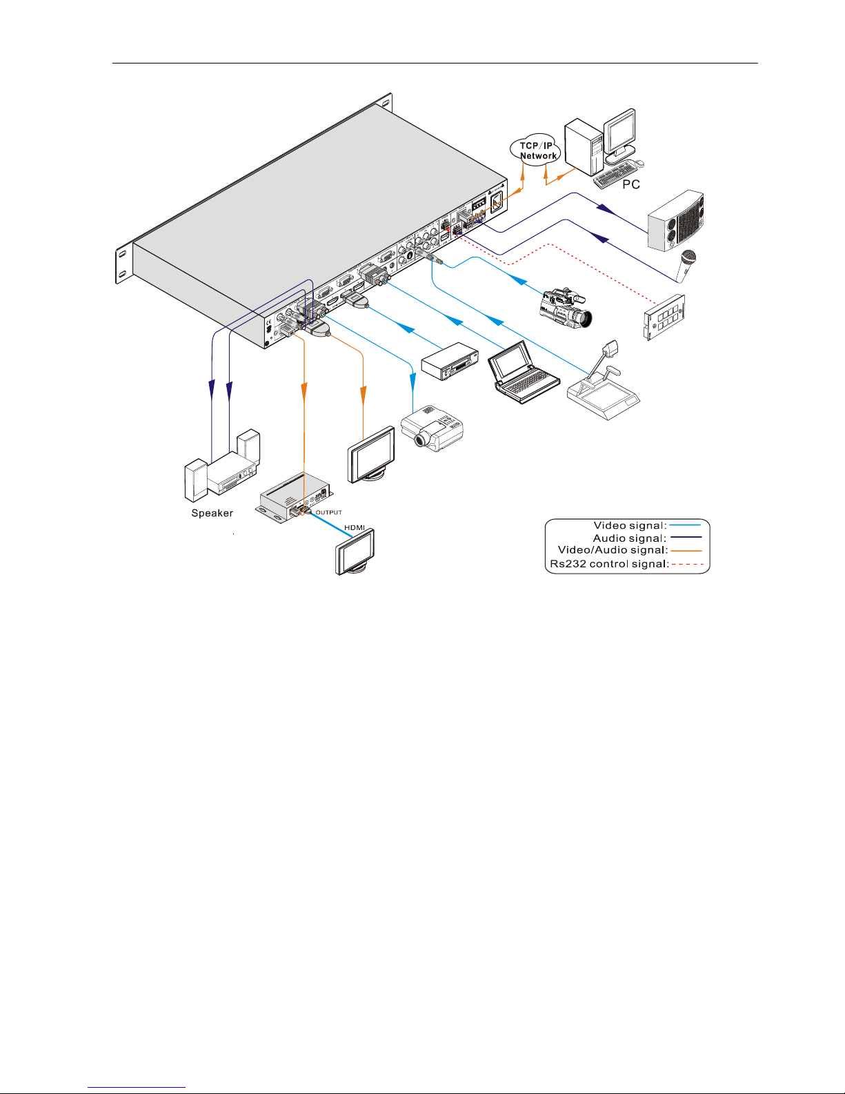
3.2. System Diagram
Scaler Switcher with Digital Amplifier-TN
4
3.3. Connection Procedures
Step1. Connect source devices (e.g. PC, DVD) to video input ports with corresponding
cables. For example, connect VGA INPUTS ports and the VGA ports of source
devices via VGA cable.
Step2. Connect the corresponding audio source to the corresponding AUDIO INPUT
port of MP-SC-12D-TN with audio cable separately. C-VIDEO1 shares the same
audio input port with S-VIDEO3; Pr-Pb-Y shares the same audio input port with
C-VIDEO4, you can select either side as audio input port.
Step3. Connect a microphone to the MIC input port; plug an audio source device or a
wireless microphone to the LINE port.
Step4. Connect a control device (e.g. a PC) to the TCP/IP ports or RS232 sockets of
MP-SC-12D-TN. Send commands to control MP-SC-12D-TN via control
software.
Step5. Connect the HDMI HDBT port of MP-SC-12D-TN with HDMI twisted pair
Receiver with PoC to extend the signal.
Step6. Connect display devices to video output ports; connect earphones/amplifiers to
Rs232
PTN control panel
VIS
HDTV
Projector
DV Camera
Speaker
M
P
S
C
1
2
D
T
N
-
-
-
Laptop
CAT5e
60m
DVD
MIC
HDTV
Receiver
 Loading...