

Miles Industries Ventana Operating Instructions Manual
Ventana
Direct Vent Zero Clearance Fireplace
1200EAP (LPG) ONLY
Installation & Operating Instructions
INSTALLER: Leave this manual with the appliance.
CONSUMER: Retain this manual for future reference.
WARNING: If the information in these
instructions is not followed exactly, a re
or explosion may result causing property
damage, personal injury or loss of life.
Do not store or use gasoline or other
ammable vapors and liquids in the vicinity
of this or any other appliance.
WHAT TO DO IF YOU SMELL GAS
• Do not try to light the appliance.
• Do not touch any electrical switch; do not
use any phone in your building.
• Immediately call your gas supplier from
a neighbor’s phone. Follow the gas
supplier’s instructions.
• If you cannot reach your gas supplier, call
the re department.
Installation and service must be performed
by a qualied installer, service agency or the
gas supplier.
PLEASE READ THIS MANUAL BEFORE
INSTALLING AND OPERATING THIS
APPLIANCE.
This appliance may be installed in an
after-market permanently located,
manufactured (mobile) home where not
prohibited by local codes.
This appliance is only for use with the type
of gas indicated on the rating plate. This
appliance is not convertible for use with
other gases, unless a certied kit is used.
This appliance is a domestic room-heating
appliance. It must not be used for any other
purposes such as drying clothes, etc.
This appliance is suitable for installation in a
bedroom or bed sitting room.
Massachusetts: The piping and nal
gas connection must be performed by a
licensed plumber or gas tter in the State of
Massachusetts. Also, see Carbon Monoxide
Detector requirements under “Safety and
Warning Information” on page 5.
4001272-06
©2007, Miles Industries Ltd.
Manufactured by
MILES INDUSTRIES LTD.
British Columbia, Canada
www.valorreplaces.com
CAUTION—HOT! HOT! HOT!
This appliance is a HEATING appliance and it becomes very hot when in operation.
UNDER ANY CIRCUMSTANCES, DO NOT PLACE any object, furniture, draperies or other
item LESS THAN 36” (0.9 m) IN FRONT OF THE FIREPLACE.
CHILDREN and PETS
Radiant heat can heat surfaces such as the hearth in front of the replace to temperatures
that, although approved safe, can be quite uncomfortable to touch or step on—particularly
for children and pets. Children and pets should always be supervised when in the room
where the appliance is located. Remote control handset should be kept out of reach of
children. In the presence of children, we STRONGLY RECOMMEND that you install in front
of the replace: a re screen, doors or, to protect young toddlers, a “hearth gate”—see
Options on page 40.
HOT SURFACES
Be aware that, although safe, some combustible materials and nishes, even though
installed at listed clearances may, over time, discolor, warp or show cracks. The 1200DV
requires the installation of the cement board provided with the engine.
Convective heat will exit the unit and travel up the wall surface if not impeded. Protruding
mantels and projections can help direct the heat away from the wall. AVOID PLACING heat
sensitive items such as televisions, paintings, decorations, etc. above replaces or near the
edge of protrusions unless appropriate.
The information contained in this installation manual is believed to be correct at the time of printing.
Miles Industries Ltd. reserves the right to change or modify any information or specications without
notice. Miles Industries Ltd. grants no warranty, implied or stated, for the installation or maintenance
of your heater, and assumes no responsibility for any consequential damage(s).
We recommend that our gas
hearth products be installed and
serviced by professionals who
are certied in the United States
by NFI (National Fireplace
Institute®).
190 – 2255 Dollarton Highway, North Vancouver B.C, CANADA. V7H 3B1
Tel. (604) 984-3496 Fax (604) 984-0246
© Copyright Miles Industries Ltd., 2007
2
Designed and Manufactured by
Miles Industries Ltd.
www.milesreplaces.com
Contents
Safety and Warning Information...................................................................4
Specications ................................................................................................7
Overview .........................................................................................................8
Dimensions ....................................................................................................9
Location ..........................................................................................................9
Mantel Clearances .......................................................................................10
Hearth Requirements ..................................................................................12
Framing .........................................................................................................15
Venting ..........................................................................................................16
Installation Planning ....................................................................................21
Appliance Preparation .................................................................................22
Supply Gas ...................................................................................................23
Ceramic Bricks .............................................................................................25
Ceramic Logs ...............................................................................................26
Window Retting ........................................................................................28
Decorative Lighting Electrical Installation ...............................................28
Operation Check & Aeration Settings Adjustment ...................................29
Optional Wall Switch Kit Installation..........................................................30
Window Skirt and Side Doors Installation ................................................31
Remote Control Handset Wall Holder Installation ....................................31
Owner’s Information ....................................................................................32
Lighting Instructions ...................................................................................38
Wiring Diagrams ..........................................................................................39
Options .........................................................................................................40
Warranty .......................................................................................................41
Spare Parts ...................................................................................................42
3

Safety and Warning Information
READ and UNDERSTAND all instructions carefully
before starting the installation. FAILURE TO FOLLOW
these installation instructions may result in possible re
hazard and will void the warranty.
Prior to the rst ring of the replace, READ the Owner’s
Information Section of this manual.
DO NOT USE this appliance if any part has been under
water. Immediately, CALL a qualied service technician
to inspect the unit and to replace any part of the control
system and any gas control that has been under water.
THIS UNIT IS NOT FOR USE WITH SOLID FUEL.
Installation and repair should be PERFORMED by a
qualied service person. The appliance and venting
system should be INSPECTED before initial use and at
least annually by a professional service person. More
frequent cleaning may be required due to excessive lint
from carpeting, bedding, etc. It is IMPERATIVE that the
unit’s control compartment, burners, and circulating air
passageways BE KEPT CLEAN to provide for adequate
combustion and ventilation air.
Always KEEP the appliance clear and free from
combustible materials, gasoline, and other ammable
vapors and liquids.
NEVER OBSTRUCT the ow of combustion and
ventilation air. Keep the front of the appliance CLEAR
of all obstacles and materials for servicing and proper
operation.
Due to the high temperature, the appliance should be
LOCATED out of trafc areas and away from furniture
and draperies. Clothing or ammable material SHOULD
NOT BE PLACED on or near the appliance.
This unit MUST be used with a vent system as described
in this installation manual. NO OTHER vent system or
component MAY BE USED.
This gas replace and vent assembly MUST be vented
directly to the outside and MUST NEVER be attached
to a chimney serving a separate solid fuel burning
appliance. Each gas appliance MUST USE a separate
vent system. Common vent systems are PROHIBITED.
INSPECT the external vent cap on a regular basis to
make sure that no debris is interfering with the air ow.
The glass door assembly MUST be in place and sealed
before the unit can be placed into safe operation.
DO NOT OPERATE this appliance with the glass door
removed, cracked, or broken. Replacement of the glass
door should be performed by a licensed or qualied
service person. DO NOT strike or slam the glass door.
The glass door assembly SHALL ONLY be replaced as a
complete unit, as supplied by the replace manufacturer.
NO SUBSTITUTE material may be used.
DO NOT USE abrasive cleaners on the glass door
assembly. DO NOT ATTEMPT to clean the glass door
when it is hot.
TURN OFF THE GAS BEFORE servicing this appliance.
It is recommended that a qualied service technician
perform an appliance check-up at the beginning of each
heating season.
Any safety screen or guard removed for servicing MUST
BE REPLACED before operating this appliance.
DO NOT place furniture or any other combustible
household objects within 36” of the replace front.
Children and adults should be ALERTED to the hazards
of high surface temperature and should STAY AWAY to
avoid burns or clothing ignition. Young children should
be CAREFULLY SUPERVISED when they are in the
same room as the appliance.
HOT SURFACES. Be aware that, although safe, some combustible materials and nishes, even though installed at
listed clearances may, over time, discolor, warp or show cracks. The 1200DV requires the installation of the cement
board provided with the engine.
Convective heat will exit the unit and travel up the wall surface if not impeded. Protruding mantels and projections
can help direct the heat away from the wall. AVOID PLACING heat sensitive items such as televisions, paintings,
decorations, etc. above replaces or near the edge of protrusions unless appropriate.
Radiant heat can heat surfaces such as the hearth in front of the replace to temperatures that, although approved
safe, can be quite uncomfortable to touch or step on—particularly for children and pets. Accessory screens and
guards will reduce the radiant heat on these surfaces.
4

Safety and Warning Information
State of California. Proposition 65 Warning.
Fuels used in gas, wood-burning or oil red appliances,
and the products of combustion of such fuels, contain
chemicals known to the State of California to cause
cancer, birth defects and other reproductive harm.
California Health & Safety Code Sec. 25249.6.
State of Massachusetts Carbon Monoxide Detector/Vent Terminal Signage Requirements
For all side wall horizontally vented gas fueled equipment
installed in every dwelling, building or structure used in
whole or in part for residential purposes, including those
owned or operated by the Commonwealth and where
the side wall exhaust vent termination is less than seven
(7) feet above nished grade in the area of the venting,
including but not limited to decks and porches, the
following requirements shall be satised:
1. INSTALLATION OF CARBON MONOXIDE
DETECTORS. At the time of installation of the side wall
horizontal vented gas fueled equipment, the installing
plumber or gas tter shall observe that a hard wired
carbon monoxide detector with an alarm and battery
back-up is installed on the oor level where the gas
equipment is to be installed. In addition, the installing
plumber or gas tter shall observe that a battery operated
or hard wired carbon monoxide detector with an alarm is
installed on each additional level of the dwelling, building
or structure served by the side wall horizontal vented
gas fueled equipment. It shall be the responsibility of
the property owner to secure the services of qualied
licensed professionals for the installation of hard wired
carbon monoxide detectors.
2. APPROVED CARBON MONOXIDE DETECTORS.
Each carbon monoxide detector as required in
accordance with the above provisions shall comply
with NFPA 720 and be ANSI/UL 2034 listed and IAS
certied.
3. SIGNAGE. A metal or plastic identication plate shall
be permanently mounted to the exterior of the building at
a minimum height of eight (8) feet above grade directly
in line with the exhaust vent terminal for the horizontally
vented gas fueled heating appliance or equipment. The
sign shall read, in print size no less than one-half (1/2)
inch in size, “GAS VENT DIRECTLY BELOW. KEEP
CLEAR OF ALL OBSTRUCTIONS”.
4. INSPECTION. The state or local gas inspector of the
side wall horizontally vented gas fueled equipment shall
not approve the installation unless, upon inspection,
the inspector observes carbon monoxide detectors and
signage installed in accordance with the provisions of
248 CMR 5.08(2)(a)1 through 4.
(b) EXEMPTIONS: The following equipment is exempt
from 248 CMR 5.08(2)(a)1 through 4:
a. In the event that the side wall horizontally vented gas
fueled equipment is installed in a crawl space or an attic,
the hard wired carbon monoxide detector with alarm and
battery back-up may be installed on the next adjacent
oor level.
b. In the event that the requirements of this subdivision
can not be met at the time of completion of installation,
the owner shall have a period of thirty (30) days to
comply with the above requirements; provided, however,
that during said thirty (30) day period, a battery operated
carbon monoxide detector with an alarm shall be
installed.
1. The equipment listed in Chapter 10 entitled “Equipment
Not Required To Be Vented” in the most current edition
of NFPA 54 as adopted by the Board; and
2. Product Approved side wall horizontally vented
gas fueled equipment installed in a room or structure
separate from the dwelling, building or structure used in
whole or in part for residential purposes.
5

Safety and Warning Information
(c) MANUFACTURER REQUIREMENTS - GAS
EQUIPMENT VENTING SYSTEM PROVIDED. When the
manufacturer of Product Approved side wall horizontally
vented gas equipment provides a venting system design
or venting system components with the equipment, the
instructions provided by the manufacturer for installation
of the equipment and the venting system shall include:
1. Detailed instructions for the installation of the venting
system design or the venting system components; and
2. A complete parts list for the venting system design or
venting system.
(d) MANUFACTURER REQUIREMENTS - GAS
EQUIPMENT VENTING SYSTEM NOT PROVIDED.
When the manufacturer of a Product Approved side
wall horizontally vented gas fueled equipment does not
provide the parts for venting the ue gases, but identies
“special venting systems”, the following requirements
shall be satised by the manufacturer:
1. The referenced “special venting system” instructions
shall be included with the appliance or equipment
installation instructions; and
2. The “special venting systems” shall be Product
Approved by the Board, and the instructions for that
system shall include a parts list and detailed installation
instructions.
(e) A copy of all installation instructions for all Product
Approved side wall horizontally vented gas fueled
equipment, all venting instructions, all parts lists for
venting instructions, and/or all venting design instructions
shall remain with the appliance or equipment at the
completion of the installation.
6
Specications
Approval & Codes
This appliance is certied to ANSI Z21.88-2007 / CSA
2.33-2007 Vented Gas Fireplace Heater standard for
use in Canada and USA, and to CGA 2.17-91 High
Altitude Standard in Canada. This appliance is for direct
vent installations.
This appliance complies with CGA P.4.1 Testing method
for measuring annual replace efciencies.
The installation must conform to local codes or, in the
absence of local codes, with the National Fuel Gas Code,
ANSI Z223.1 or the Natural Gas and Propane Installation
Code CAN/CGA-B149. Only qualied licensed or trained
personnel should install this appliance.
This appliance must be electrically grounded in
accordance with local codes, or, in the absence of local
codes, with the National Electrical Code, ANSI/NFPA 70
or the Canadian Electrical Code, CSA C22.1.
Ratings
Model N P
Gas Natural Propane
Altitude (Ft.)* 0-4,500 feet*
Input Maximum (Btu/h) 36,000 31,000
Input Minimum (Btu/h) 15,000 15,000
Manifold Pressure (in
w.c.)
Minimum Supply
Pressure (in w.c.)
Maximum Supply
Pressure (in w.c.)
Main Burner Injector
Marking
Pilot Injector Marking #62 #30
Min. Rate By-Pass Screw #190 #125
3.6” 10.5”
5”
10” 14”
Cat #
82-1200
11”
Cat #
92-360
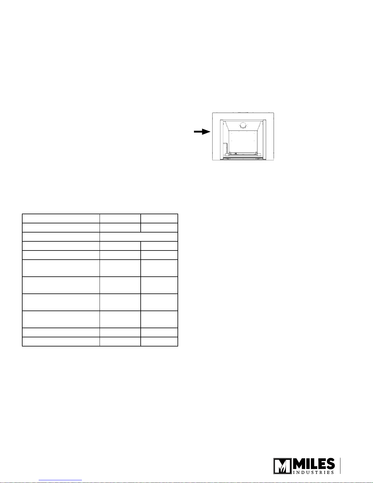
Supply Gas
Heater engine 1200EAN is used with natural gas.
Heater engine 1200EAP is used with propane gas.
The supply pressure must be between the limits shown
in the Ratings section above.
The supply connection is 3/8” NPT female and located
on the left hand side of the rebox.
X
Conversion Kits
The 1200 Ventana is supplied as natural gas or
propane gas and is eld convertible between fuels. See
instructions packaged with the conversion kit for further
information.
Electrical
The 1200 does not require an electrical power source
to operate as a heater. However, it requires electrical
power to operate its decorative hearth light.
*High Altitude Installations
Input ratings are shown in BTU per hour and are certied
without deration for elevations up to 4,500 feet (1,370
m) above sea level.
For elevations above 4,500 feet (1,370 m) in USA,
installations must be in accordance with the current ANSI
Z223.1 and/or local codes having jurisdiction. Heating
value of gas in some areas is reduced to compensate
for elevation—consult your local gas utility to conrm.
For installations at elevations above 4,500 feet (1,370
m) in Canada, please consult provincial and/or local
authorities having jurisdiction.
7
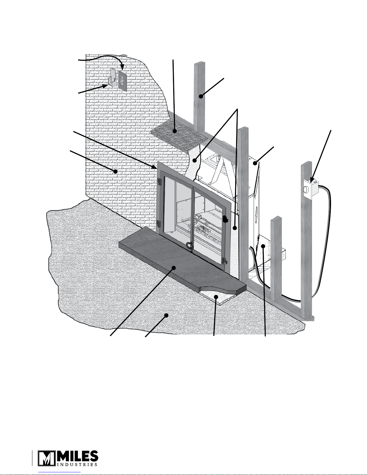
Overview
Fire On/Off
Wall Switch
(optional)
Remote
Handset
Wall Holder
Optional Doors and
Plates—see Options
Wall Finish
Mantel—See Mantel Clearances
Framing—See Framing
Cement Board
Decorative Light
Dimmer Switch
1200EAN
Non-combustible Hearth—
See Hearth Requirements
8
Combustible Floor
1/2” Insulation Board
When the appliance is installed
directly on carpeting, tile or other
combustible material other than
wood ooring, the appliance shall
be installed on a metal or wood
panel extending the full width
and depth of the appliance
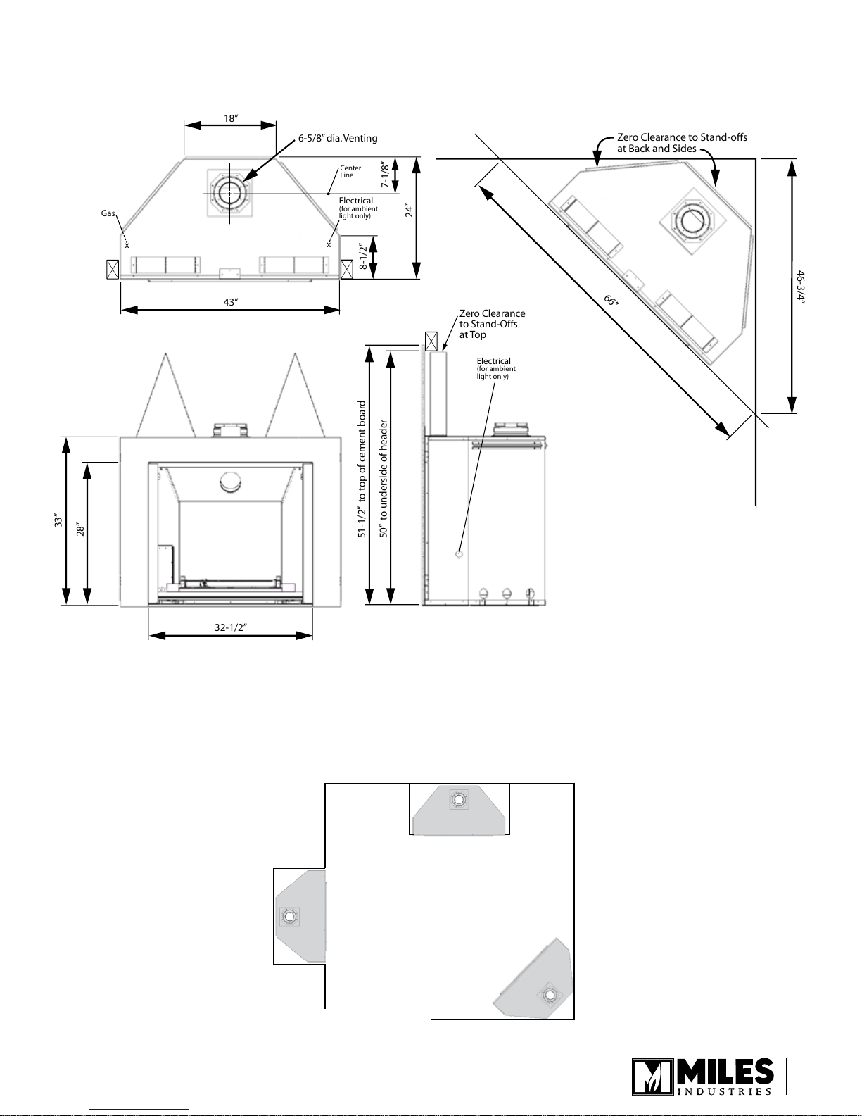
Dimensions
18”
43”
32-1/2”
33”
28”
24”
7-1/8”
8-1/2”
51-1/2” to top of cement board
50” to underside of header
Electrical
(for ambient
light only)
Electrical
(for ambient
light only)
Zero Clearance
to Stand-Offs
at Top
Gas
x
x
6-5/8” dia. Venting
Center
Line
66”
46-3/4”
Zero Clearance to Stand-offs
at Back and Sides
Location
9
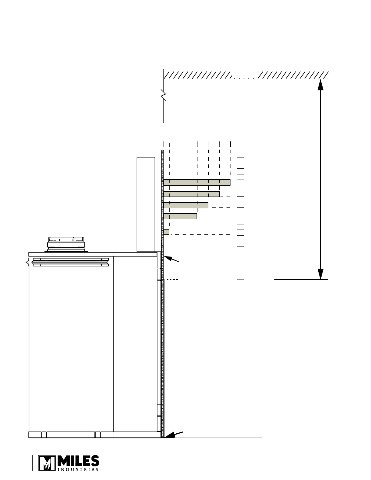
Combustible Mantel—Left Side View
Bottom of Unit
Face of
Cement Board
0 2”
4”
6”
8” 10”
12”
50”
45”
43”
41”
39”
36”
33”
28”
Mantel Projection
(from Face of Cement Board)
Mantel
Height
(from
Bottom
of Unit)
Fireplace
Opening
Firebox Height
Ceiling
36” Min. to Ceiling
Mantel Clearances
10
Left Side View
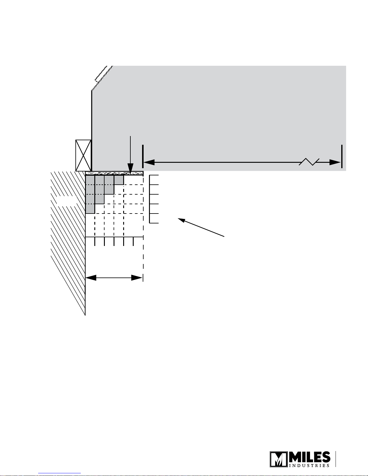
2” 1”
4”5”
3”
2”
1”
4”
5”
3”
32-1/2”
Fireplace Opening
Wall
Min. 6”
between edge
of opening
and wall
Face of
Cement
Board
Note
Right Side Clearances
are the same and can
be used in combination
Mantel Clearances
Combustible Sidewall / Mantel Leg—Top View
FIREPLACE
Top View
11
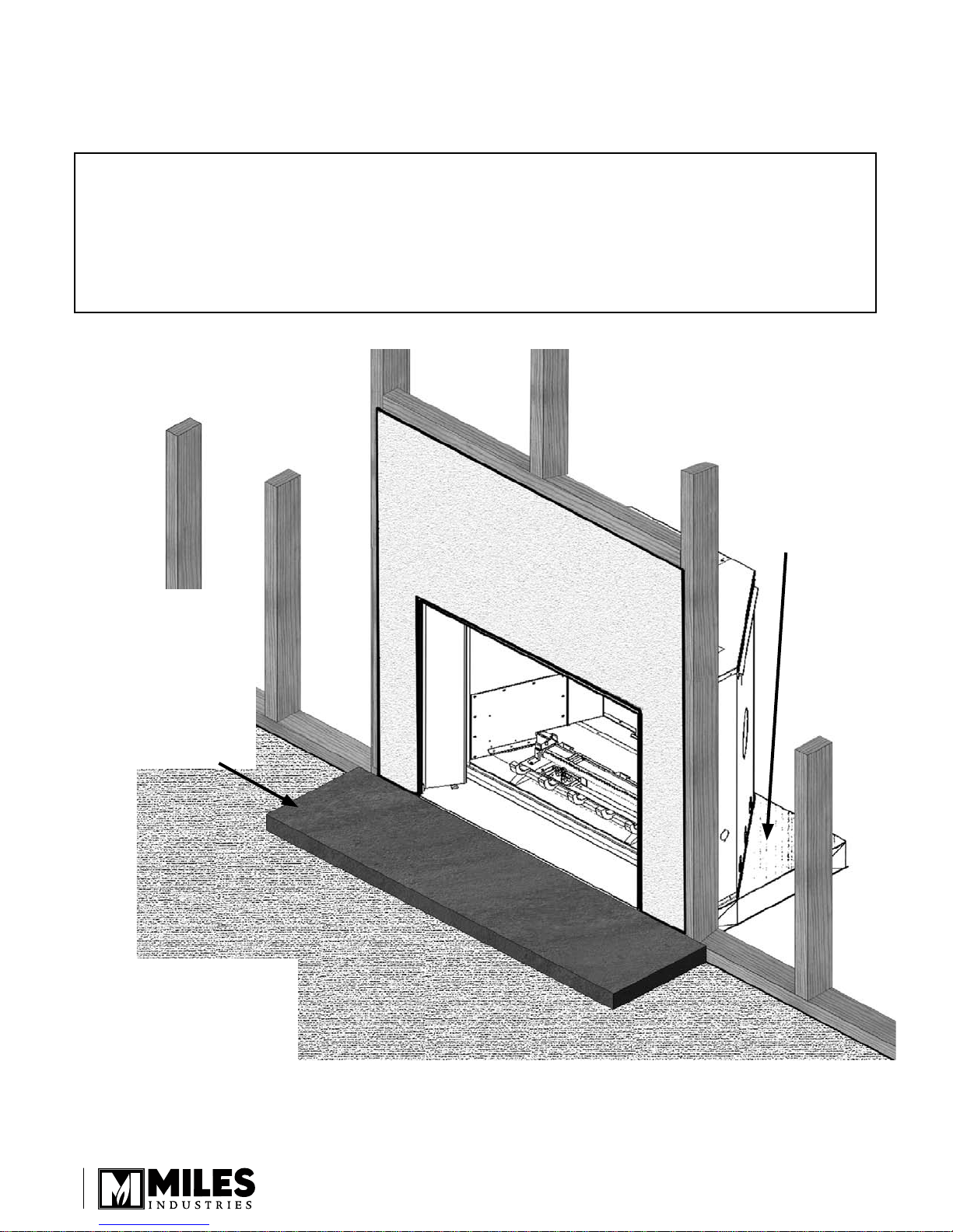
Hearth Requirements
General Hearth Considerations
SAFETY WARNING! The Ventana is a very effective radiant heater. The hearth/oor in front of
the heater can get very hot (in excess of 200ºF). Locating the unit raised above the hearth/oor
or adding one of the optional screen fronts or a generic freestanding screen in front of the unit
can greatly reduce hearth temperatures. Any hearth within 4” of the base of the heater must
be constructed of non-combustible materials (see diagrams in the following pages). Note that
some materials, although safe can degrade due to heat—take this into consideration when
choosing materials.
When the appliance
is installed directly on
carpeting, tile or other
combustible material
other than wood ooring,
the appliance shall be
installed on a metal or
wood panel extending the
full width and depth of the
appliance
Top of Finished Hearth
Must Be Flush With
Bottom of Heater to
accommodate some
optional mantels and
trims. See Option section
towards the end of this
manual for optional
accessories.
NOTE:
Unit will need to be raised
•
in almost every case to
accommodate hearth or
combustible ooring.
Non-combustible hearth
•
required if bottom of
replace is less than 4” from
combustible oor in front.
12
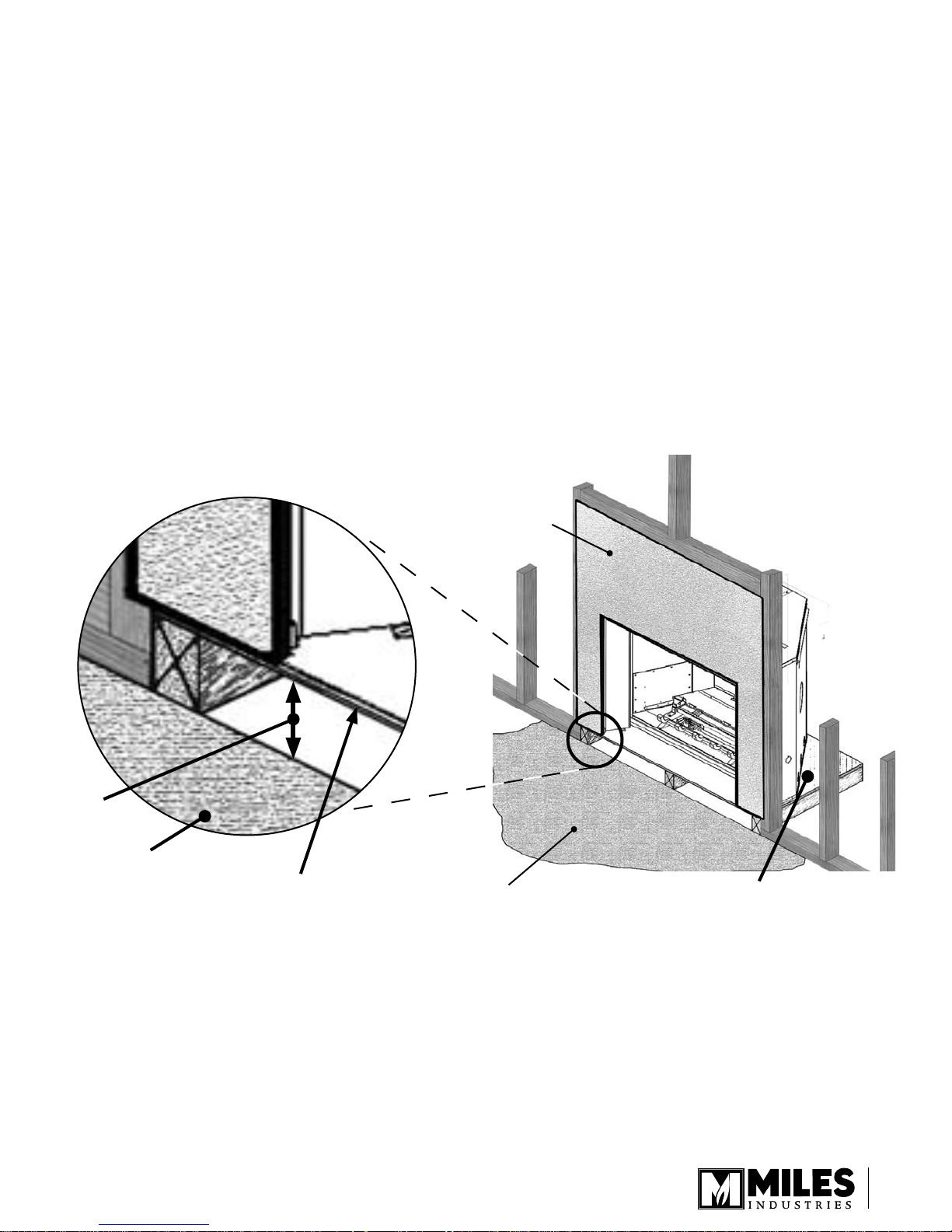
Hearth Requirements
Rules
Any hearth/oor in front of replace within 4” of bottom of unit must be non-combustible and project a minimum
1.
distance as shown on page 14. The hearth/oor must have a non-combustible nish applied over the 1/2”
insulation board provided with the engine. This insulation board acts as a thermal break.
Minimum hearth projection is determined by a combination of the height of the hearth above the surface of
2.
combustible oor or carpet and distance between hearth and bottom of replace.
Combustible baseboards (1” thick or less) located on wall are acceptable provided they are located below the
3.
base of the raised replace.
Unit Raised Above Combustible Hearth or Floor
Face of
Cement
Board
4” MIN.
Combustible
Floor
Base of Fireplace
Top Face of
Combustible
Floor or
Carpet
When the appliance is installed directly on
carpeting, tile or other combustible material
other than wood ooring, the appliance
shall be installed on a metal or wood panel
extending the full width and depth of the
appliance
13
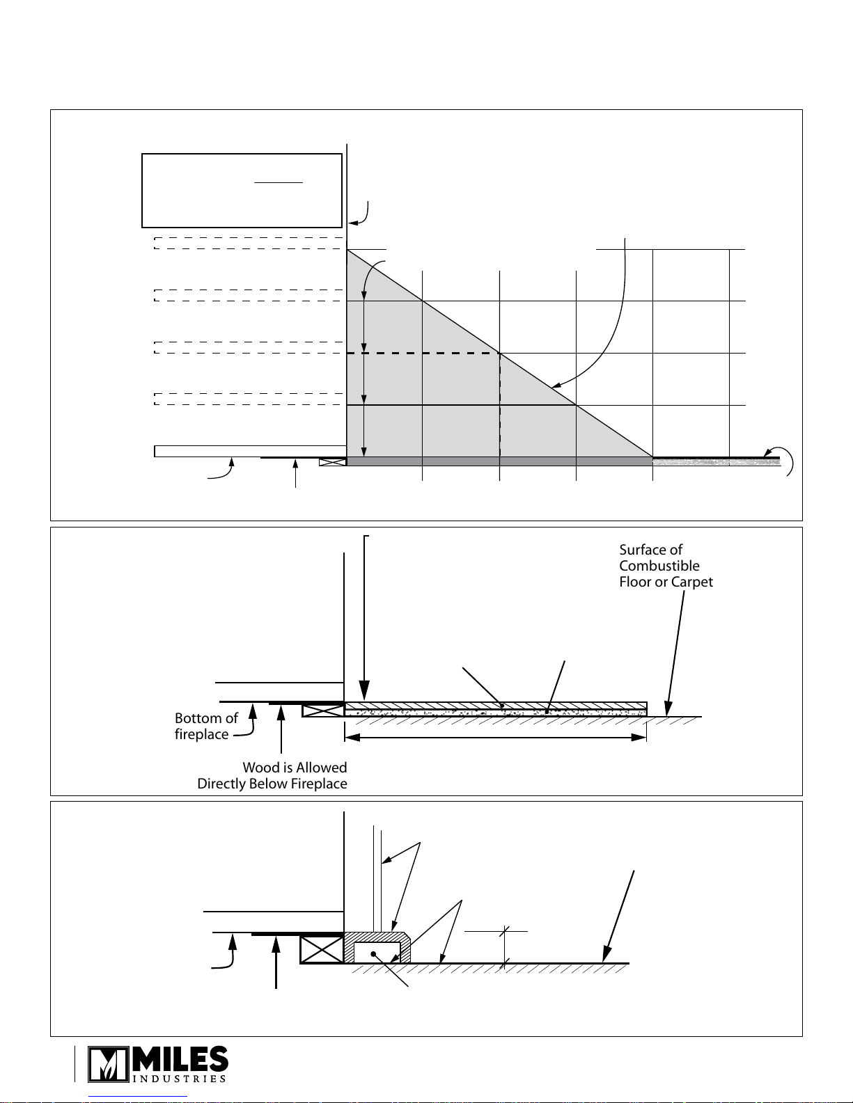
Front of Fireplace
(Surface of Cement Board)
Min. Hearth Projection
Required to Protect
Combustible Floor
Surface of
Combustible
Floor or Carpet
Bottom of
fireplace
When using Optional Trims and
Mantels, Surface of Finished
Hearth Must Be Flush With
Bottom of Fireplace
(otherwise, optional trims will not fit)
Surface of Hearth
(non-combutible material on
non-combustible insulation board
see diagram below)
Wood is Allowed
Directly Below Fireplace
Raised 1”
above combustible floor
Raised 2”
above combustible floor
Raised 3”
above combustible floor
Raised 4”
above combustible floor
3” 6” 9” 12”
4”
3”
2”
1”
Surface of
Combustible
Floor or Carpet
Bottom of
fireplace
Wood is Allowed
Directly Below Fireplace
Combustible
Floor Allowed
2 “
616STK/617STK
Leg & Hearth
Air Gap
Surface of
Combustible
Floor or Carpet
Bottom of
fireplace
Wood is Allowed
Directly Below Fireplace
Non-Combustible
Finish
1/2” Insulation
Board supplied
with fireplace
DO NOT FINISH ABOVE
THIS HEIGHT!
(Hearth MUST be at this height
when using certain accessories)
See Chart above for Required Projection
Hearth Requirements
Unit With Site-Built Non-Combustible Hearth Extending
Example: If the replace is raised 2” above
combustible oor, the non-combustible-ushwith-bottom-of-replace hearth must project a
min. of 6” in front of the replace.
Non-combustible substrate
construction detail
Using 616/617STK Stone Trim Kits
14
 Loading...