

Miles Industries 1500IN (NG), 1500IP (LPG), L1 1500IN, L1 1500IP Installation And Operating Instructions Manual
L1
Direct Vent
Zero Clearance Fireplace
1500IN (NG) & 1500IP (LPG)
Installation & Operating Instructions
HOT GLASS WILL
CAUSE BURNS.
DO NOT TOUCH GLASS
UNTIL COOLED.
INSTALLER: Leave this manual
with the appliance.
CONSUMER: Retain this manual
for future reference.
NEVER ALLOW CHILDREN
TO TOUCH GLASS.
WARNING: If the information in these
instructions is not followed exactly, a fi re
or explosion may result causing property
damage, personal injury or loss of life.
Do not store or use gasoline or other
fl ammable vapors and liquids in the vicinity
of this or any other appliance.
WHAT TO DO IF YOU SMELL GAS
• Do not try to light the appliance.
• Do not touch any electrical switch; do not
use any phone in your building.
• Immediately call your gas supplier from
a neighbor’s phone. Follow the gas
supplier’s instructions.
• If you cannot reach your gas supplier, call
the fi re department.
Installation and service must be performed
by a qualifi ed installer, service agency or the
gas supplier.
Please read this manual
BEFORE installing and operating
this appliance.
This appliance may be installed in an
after-market permanently located,
manufactured (mobile) home where not
prohibited by local codes.
This appliance is only for use with the type
of gas indicated on the rating plate. This
appliance is not convertible for use with
other gases, unless a certifi ed kit is used.
This appliance is a domestic room-heating
appliance. It must not be used for any other
purposes such as drying clothes, etc.
This appliance is suitable for installation in a
bedroom or bed sitting room.
Massachusetts: The piping and fi nal
gas connection must be performed by a
licensed plumber or gas fi tter in the State of
Massachusetts. Also, see Carbon Monoxide
Detector requirements under “Important
Safety Information” on page 6.
This manual is available in French upon request.
4002873-01
©2011, Miles Industries Ltd.
Manufactured by
MILES INDUSTRIES LTD., British Columbia, Canada
www.valorfi replaces.com
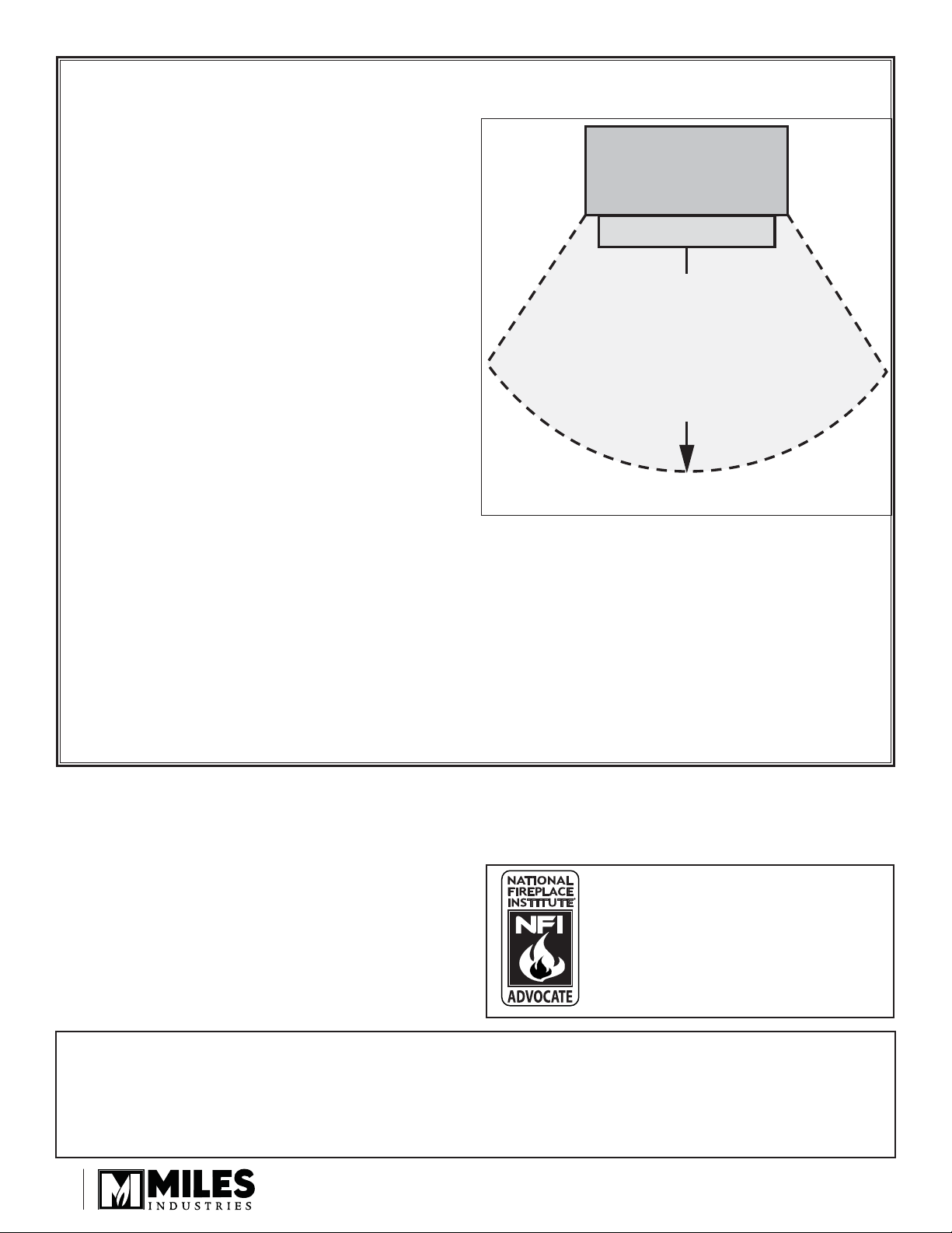
CAUTION—HOT! HOT! HOT!
This appliance is a HEATING appliance and it
becomes very hot when in operation.
UNDER ANY CIRCUMSTANCES, DO NOT
PLACE any object, furniture, draperies or
other item LESS THAN 36 inches (0.9 m) IN
FRONT OF THE FIREPLACE.
CHILDREN and PETS
Radiant heat heats surfaces such as the
glass and hearth in front of the fi replace
to temperatures that, although approved
safe, are still dangerous to touch and
uncomfortable too step on. Young children
and pets must always be supervised when
in the room where the appliance is located.
The remote control handset should be kept
out of reach of children. To ensure safety,
we STRONGLY RECOMMEND that you install
in front of the fi replace: a fi re screen or, to
protect young toddlers, a hearth gate—see Options on page 45.
HOT SURFACES
Be aware that, although safe, some combustible materials and fi nishes, even though
installed at listed clearances may, over time, discolor, warp or show cracks. The 1500
requires the installation of the cement board provided with the engine.
Convective heat will exit the unit and travel up the wall surface if not impeded. Protruding
mantels and projections can help direct the heat away from the wall. AVOID PLACING heat
sensitive items such as televisions, paintings, decorations, etc. above fi replaces or near the
edge of protrusions unless appropriate.
furniture or other objects
in this space in front of
Fireplace
Hearth
Do not put
the replace:
36” (0.9 m)
The information contained in this installation
manual is believed to be correct at the time of
printing. Miles Industries Ltd. reserves the right to
change or modify any information or specifi cations
without notice. Miles Industries Ltd. grants no
warranty, implied or stated, for the installation
or maintenance of your heater, and assumes no
responsibility for any consequential damage(s).
Designed and Manufactured by / for
Miles Industries Ltd.
190–2255 Dollarton Highway, North Vancouver, BC, CANADA V7H 3B1
Tel. 604-984-3496 Fax 604-984-0246
www.valorfi replaces.com
© Copyright Miles Industries Ltd., 2011
2
We recommend that our gas
hearth products be installed and
serviced by professionals who
are certifi ed in the United States
by NFI (National Fireplace
Institute®).
Safety and Your Fireplace
Safety and Your Fireplace
KEEP YOUR FAMILY SAFE!
Read BEFORE using your fi replace!
All parts of your Valor fi replace get
EXTREMELY HOT!
• To prevent severe burns and injuries,
install a screen or physical barrier to
prevent direct contact with the glass.
• Follow the safety instructions below
and be sure everyone in your
household understands this burn
hazard:
◊ The surfaces on your fi replace
get EXTREMELY HOT!
◊ The glass on the front of the
fi replace reaches EXTREMELY
HIGH temperatures and can
cause severe burns if touched.
◊ Keep children away from an
operating fi replace. Always
closely supervise children in
any room where a fi replace is
operating to prevent contact
with glass.
◊ Keep the remote control
handset and wall switch out of
reach of children.
◊ Keep clothing, furniture, toys,
gasoline, and other fl ammable
liquids away from the fi replace.
◊ Even after the gas is turned
off, fi replace surfaces remain
extremely hot.
• Read Important Safety Information
on page 5.
PROTECT YOUR CHILDREN
AGAINST THE RISK OF SEVERE BURNS
3

Table of Contents
Safety and Your Fireplace ..................................................................3
Important Safety Information .............................................................5
Specifi cations ......................................................................................8
Overview ..............................................................................................9
Dimensions & Location ......................................................................10
Mantel & Hearth Clearances ..............................................................11
Framing Requirements .......................................................................13
Venting .................................................................................................16
Installation Planning ...........................................................................21
Appliance Preparation ........................................................................22
Window Removal ................................................................................25
Electrical Wiring (for optional accessories) .....................................26
Supply Gas Installation ......................................................................27
Liners Installation ...............................................................................29
Long Beach Driftwood Kit Installation ..............................................30
Murano Glass Fire Installation ...........................................................32
Window Refi tting .................................................................................34
Wall Switch Kit Installation ................................................................34
Remote Control Initial Set-up ............................................................36
Operation Check & Aeration Settings Adjustment ..........................37
Remote Control Handset Wall Holder Installation ...........................37
Owner’s Information ...........................................................................38
Remote Control Operation .................................................................42
Options ................................................................................................45
Lighting Instructions ..........................................................................46
Wiring Diagram ...................................................................................47
Approved Venting Components ........................................................48
Warranty ...............................................................................................50
Spare Parts ..........................................................................................51
4
Important Safety Information
READ and UNDERSTAND all instructions carefully
before starting the installation. FAILURE TO
FOLLOW these installation instructions may result in
possible fi re hazard and will void the warranty.
Prior to the fi rst fi ring of the fi replace, READ the
Owner’s Information section of this manual.
DO NOT USE this appliance if any part has been
under water. Immediately, CALL a qualifi ed service
technician to inspect the unit and to replace any part
of the control system and any gas control that has
been under water.
THIS UNIT IS NOT FOR USE WITH SOLID FUEL.
Installation and repair should be PERFORMED
by a qualifi ed service person. The appliance and
venting system should be INSPECTED before initial
use and at least annually by a professional service
person. More frequent cleaning may be required due
to excessive lint from carpeting, bedding, etc. It is
IMPERATIVE that the unit’s control compartment,
burner, and circulating air passageways BE KEPT
CLEAN to provide for adequate combustion and
ventilation air.
Always KEEP the appliance clear and free from
combustible materials, gasoline, and other fl ammable
vapors and liquids.
NEVER OBSTRUCT the fl ow of combustion and
ventilation air. Keep the front of the appliance CLEAR
of all obstacles and materials for servicing and proper
operation.
Due to the high temperature, the appliance should be
LOCATED out of traffi c areas and away from furniture
and draperies. Clothing or fl ammable material
SHOULD NOT BE PLACED on or near the appliance.
Children and adults should be ALERTED to the
hazards of high surface temperature and should STAY
AWAY to avoid burns or clothing ignition.
This unit MUST be used with a vent system as
described in this installation manual. NO OTHER vent
system or components MAY BE USED.
This gas fi replace and vent assembly MUST be
vented directly to the outside and MUST NEVER be
attached to a chimney serving a separate solid fuel
burning appliance. Each gas appliance MUST USE
a separate vent system. Common vent systems are
PROHIBITED.
INSPECT the external vent cap on a regular basis to
make sure that no debris, plants, trees, shrubs are
interfering with the air fl ow.
The glass door assembly MUST be in place and
sealed before the unit can be placed into safe
operation.
DO NOT OPERATE this appliance with the glass
door removed, cracked, or broken. Replacement of
the glass door should be performed by a licensed or
qualifi ed service person. DO NOT strike or slam the
glass door.
The glass door assembly SHALL ONLY be replaced
as a complete unit, as supplied by the fi replace
manufacturer. NO SUBSTITUTE material may be
used.
DO NOT USE abrasive cleaners on the glass door
assembly. DO NOT ATTEMPT to clean the glass door
when it is hot.
TURN OFF the gas before servicing this appliance.
It is recommended that a qualifi ed service technician
perform an appliance check-up at the beginning of
each heating season.
Any safety screen or guard removed for servicing
MUST BE REPLACED before operating this
appliance.
DO NOT place furniture or any other combustible
household objects within 36” of the fi replace front.
YOUNG CHILDREN should be CAREFULLY
SUPERVISED when they are in the same room as
the appliance. Toddlers, young children and others
may be susceptible to ACCIDENTAL CONTACT
BURNS. A physical barrier is recommended if there
are at risk individuals in the house. To restrict access
to a fi replace or stove, INSTALL AN ADJUSTABLE
SAFETY GATE to keep toddlers, young children and
other at risk individuals out of the room and away
from hot surfaces.
BE CAREFUL not to put any decorating objects
sensitive to heat to close above or around the
fi replace as it gets very hot when operating.
DO NOT use this heater as a temporary source of
heat during construction.
This appliance is a DOMESTIC ROOM-HEATING AP-
PLIANCE. It must not be used for any other purposes
such as drying clothes, etc.
5

Important Safety Information
HOT SURFACES. Be aware that, although safe,
some combustible materials and fi nishes, even
though installed at listed clearances may, over time,
discolor, warp or show cracks. The 1500 requires the
installation of the cement board provided with the
engine.
Convective heat will exit the unit and travel up the
wall surface if not impeded. Protruding mantels and
projections can help direct the heat away from the
wall. AVOID PLACING heat sensitive items such
as televisions, paintings, decorations, etc. above
fi replaces or near the edge of protrusions unless
appropriate.
Radiant heat can heat surfaces such as the hearth in
front of the fi replace to temperatures that, although
approved safe, can be quite uncomfortable to
touch or step on—particularly for children and pets.
Accessory screens and guards will reduce the
radiant heat on these surfaces.
Operating Your Fireplace for the First
Time
When operating your new fi replace for the fi rst time,
some vapors may be released due to the burning of
curing compounds used in the manufacture of the
appliance. They may cause a slight odor and could
cause the fl ames to be the full height of the fi rebox, or
even slightly higher, for the fi rst few hours of operation.
It is also possible that these vapors could set off any
smoke detection alarms in the immediate vicinity.
These vapors are quite normal on new appliances. We
recommend opening a window to vent the room. After
a few hours use, the vapors will have disappeared and
the fl ames will be at their normal height.
State of California. Proposition 65
Warning.
Fuels used in gas, wood-burning or oil fi red appliances,
and the products of combustion of such fuels, contain
chemicals known to the State of California to cause
cancer, birth defects and other reproductive harm.
California Health & Safety Code Sec. 25249.6.
State of Massachusetts Carbon Monoxide
Detector/Vent Terminal Signage
Requirements
For all side wall horizontally vented gas fueled
equipment installed in every dwelling, building or
structure used in whole or in part for residential
purposes, including those owned or operated by the
Commonwealth and where the side wall exhaust
vent termination is less than seven (7) feet above
fi nished grade in the area of the venting, including
but not limited to decks and porches, the following
requirements shall be satisfi ed:
1. INSTALLATION OF CARBON MONOXIDE
DETECTORS. At the time of installation of the side wall
horizontal vented gas fueled equipment, the installing
plumber or gas fi tter shall observe that a hard wired
carbon monoxide detector with an alarm and battery
back-up is installed on the fl oor level where the gas
equipment is to be installed. In addition, the installing
plumber or gas fi tter shall observe that a battery
operated or hard wired carbon monoxide detector
with an alarm is installed on each additional level of
the dwelling, building or structure served by the side
wall horizontal vented gas fueled equipment. It shall
be the responsibility of the property owner to secure
the services of qualifi ed licensed professionals for the
installation of hard wired carbon monoxide detectors.
a. In the event that the side wall horizontally vented
gas fueled equipment is installed in a crawl space or
an attic, the hard wired carbon monoxide detector with
alarm and battery back-up may be installed on the next
adjacent fl oor level.
b. In the event that the requirements of this subdivision
can not be met at the time of completion of installation,
the owner shall have a period of thirty (30) days
to comply with the above requirements; provided,
however, that during said thirty (30) day period, a
battery operated carbon monoxide detector with an
alarm shall be installed.
2. APPROVED CARBON MONOXIDE DETECTORS.
Each carbon monoxide detector as required in
accordance with the above provisions shall comply
with NFPA 720 and be ANSI/UL 2034 listed and IAS
certifi ed.
6

Important Safety Information
3. SIGNAGE. A metal or plastic identifi cation plate
shall be permanently mounted to the exterior of the
building at a minimum height of eight (8) feet above
grade directly in line with the exhaust vent terminal for
the horizontally vented gas fueled heating appliance
or equipment. The sign shall read, in print size no less
than one-half (1/2) inch in size, “GAS VENT DIRECTLY
BELOW. KEEP CLEAR OF ALL OBSTRUCTIONS”.
4. INSPECTION. The state or local gas inspector of
the side wall horizontally vented gas fueled equipment
shall not approve the installation unless, upon
inspection, the inspector observes carbon monoxide
detectors and signage installed in accordance with the
provisions of 248 CMR 5.08(2)(a)1 through 4.
(b) EXEMPTIONS: The following equipment is exempt
from 248 CMR 5.08(2)(a)1 through 4:
1. The equipment listed in Chapter 10 entitled
“Equipment Not Required To Be Vented” in the most
current edition of NFPA 54 as adopted by the Board;
and
2. Product Approved side wall horizontally vented
gas fueled equipment installed in a room or structure
separate from the dwelling, building or structure used in
whole or in part for residential purposes.
(c) MANUFACTURER REQUIREMENTS - GAS
EQUIPMENT VENTING SYSTEM PROVIDED.
When the manufacturer of Product Approved side
wall horizontally vented gas equipment provides a
venting system design or venting system components
with the equipment, the instructions provided by the
manufacturer for installation of the equipment and the
venting system shall include:
1. Detailed instructions for the installation of the venting
system design or the venting system components; and
2. A complete parts list for the venting system design or
venting system.
(d) MANUFACTURER REQUIREMENTS - GAS
EQUIPMENT VENTING SYSTEM NOT PROVIDED.
When the manufacturer of a Product Approved side
wall horizontally vented gas fueled equipment does
not provide the parts for venting the fl ue gases, but
identifi es “special venting systems”, the following
requirements shall be satisfi ed by the manufacturer:
1. The referenced “special venting system” instructions
shall be included with the appliance or equipment
installation instructions; and
2. The “special venting systems” shall be Product
Approved by the Board, and the instructions for that
system shall include a parts list and detailed installation
instructions.
(e) A copy of all installation instructions for all Product
Approved side wall horizontally vented gas fueled
equipment, all venting instructions, all parts lists
for venting instructions, and/or all venting design
instructions shall remain with the appliance or
equipment at the completion of the installation.
7
Specifi cations
Approval & Codes
This appliance is certifi ed to ANSI Z21.88-2009/
CSA 2.33-2009 American National Standard / CSA
Standard for Vented Gas Fireplace Heaters for use in
Canada and USA, and to CGA 2.17-91 High Altitude
Standard in Canada. This appliance is for direct vent
installations.
This appliance complies with CSA P4.1-09 Testing
method for measuring annual fi replace effi ciencies.
The installation must conform to local codes or, in the
absence of local codes, with the National Fuel Gas
Code, ANSI Z223.1 or the Natural Gas and Propane
Installation Code CAN/CGA-B149. Only qualifi ed
licensed or trained personnel should install this
appliance.
This appliance must be electrically grounded in
accordance with local codes, or, in the absence of local
codes, with the National Electrical Code, ANSI/NFPA
70 or the Canadian Electrical Code, CSA C22.1.
Ratings
Model NP
Gas Natural Propane
Altitude (Ft.)* 0-4,500 feet*
Input Maximum (Btu/h) 30,000 28,000
Input Minimum (Btu/h) 16,000 15,000
Manifold Pressure (in
w.c.)
Minimum Supply
Pressure (in w.c.)
Maximum Supply
Pressure (in w.c.)
Main Burner Injector
Marking
Pilot Injector Marking 51 30
Min. Rate By-Pass
Screw
4.0” 9.5”
5” 11”
10” 14”
850 300
185 135
For installations at elevations above 4,500 feet
(1,370 m) in Canada, please consult provincial and/or
local authorities having jurisdiction.
Supply Gas
Heater engine 1500IN is used with natural gas.
Heater engine 1500IP is used with propane gas.
The supply pressure must be between the limits shown
in the Ratings section above.
X
The supply connection is 3/8” NPT male and located
on the left hand side of the fi rebox. A shut-off valve (not
supplied) is required on the supply line to isolate the
unit during service. See Gas Supply Installation section
for details.
Conversion Kits
The 1500 L1 is supplied as natural gas or propane gas
and is fi eld convertible between fuels. See instructions
packaged with the conversion kit for further information.
Electrical
The 1500 is designed to run on battery power and
does not require an electrical power source to operate
as a heater. However, it requires electrical power to
operate optional 1565LLK Linear Lighting Kit, 1595CFK
Circulating Fan Kit or 1270RBK Remote Blower Kit.
*High Altitude Installations
Input ratings are shown in BTU per hour and are
certifi ed without deration for elevations up to 4,500 feet
(1,370 m) above sea level.
For elevations above 4,500 feet (1,370 m) in USA,
installations must be in accordance with the current
ANSI Z223.1 and/or local codes having jurisdiction.
Heating value of gas in some areas is reduced to
compensate for elevation—consult your local gas utility
to confi rm.
8
Fire On/Off
Su
Su
nd Pla
te
(requ
ir
ed
)
555
– mounts over ceme
e;
w
550
add
mbtie fi sh ove
r
board and be
d
Wall Finis
d
board mu
st
bustible
ey
a
p
p
p
)
)
)
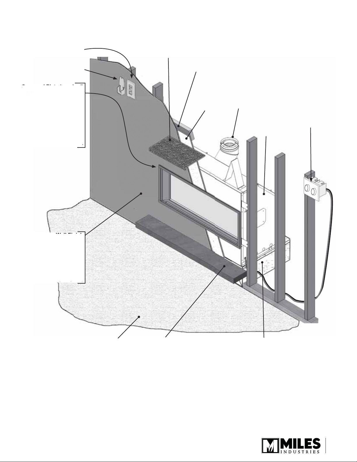
Wall Switch (20foot wire length)
Remote Handset
Wall Holder
Overview
Mantel—See Mantel & Hearth Clearances
Framing—See Framing Requirements
rrou
Narrow 1” Trim 1
board, not adjustabl
ider 3-1/2” Trim 1
djustable, accepts up
to 1”
nt
Any wall fi nishes applie
ver cement
non-com
ombustible mantel
are ok provided th
nform to ch
LFB
itional non-
hin
trim
ee
. 11
Non-combustible
cement board
– supplied with
appliance
Supplied as
vertical outlet, fi eld
convertible to
horizontal outlet.
1500
Optional Decorative
Light Dimmer
Switch and Fan
Speed Control—not
provided. Consult
your electrician.
Combustible Floor
Hearth: not required.
If used, must be minimum 4”
below fi replace opening.
Combustible Framing Allowed
Beneath Fireplace. When the
appliance is installed directly on
carpeting, tile or other combustible
material other than wood fl ooring, the
appliance shall be installed on a metal
or wood panel extending the full width
and recessed depth of the appliance.
9
(
)
p
d
(
)
f
allet Pot
RBK Duct
l
)
e
t
Z
s
r
Center
e
6-5/
V
f
f
outlet
t
ld
r
tet
appl
4
)
(
)
/
)
)383
”
)
/
”
)
(
)
(
)
/
”
)
/
”
)
4
)
)
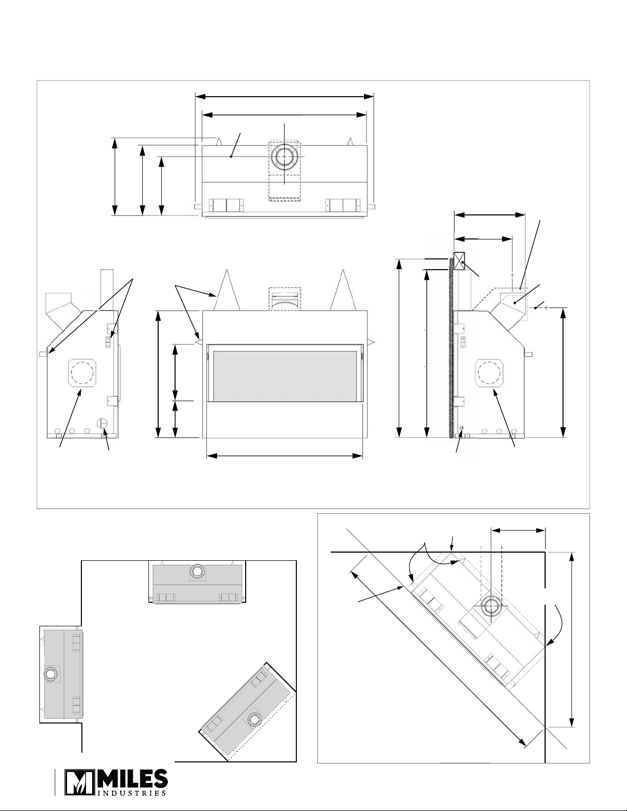
Zero Clearance
to Stand-offs
at Back and Sides
Zero Clearance
at back corners
78” (1981 mm)
55-1/8” (1400 mm)
Zero Clearance
at back corners
Dimensions & Location
Dimensions
8
19-7
505 mm
16”
457 mm
5-1
383 mm
18”
ero Clearance
nd-Off
2
822 mm
14-1
32-3/8”
8
9-3
369 mm
238 mm
6” (1168 mm
2” (1067 mm
n
Top View
1130 mm
1092 mm
of cement boar
4-1/2”
43”
to to
header
to underside o
18-1/2
469 mm
mm
Heade
Heat shie
equired fo
ear ven
ications
8” dia.
enting
ield-
onvertible
rom top to
ear
enter of ven
841 mm
3-1/8”
1270
Kit Inlet
(remove p
Location
10
ate
Gas Lin
Access Poin
39-11/16” (1009 mm
ectric
270RBK Duct
it Inlet
remove plate)
Front ViewLeft Side View Right Side View
Corner Dimensions

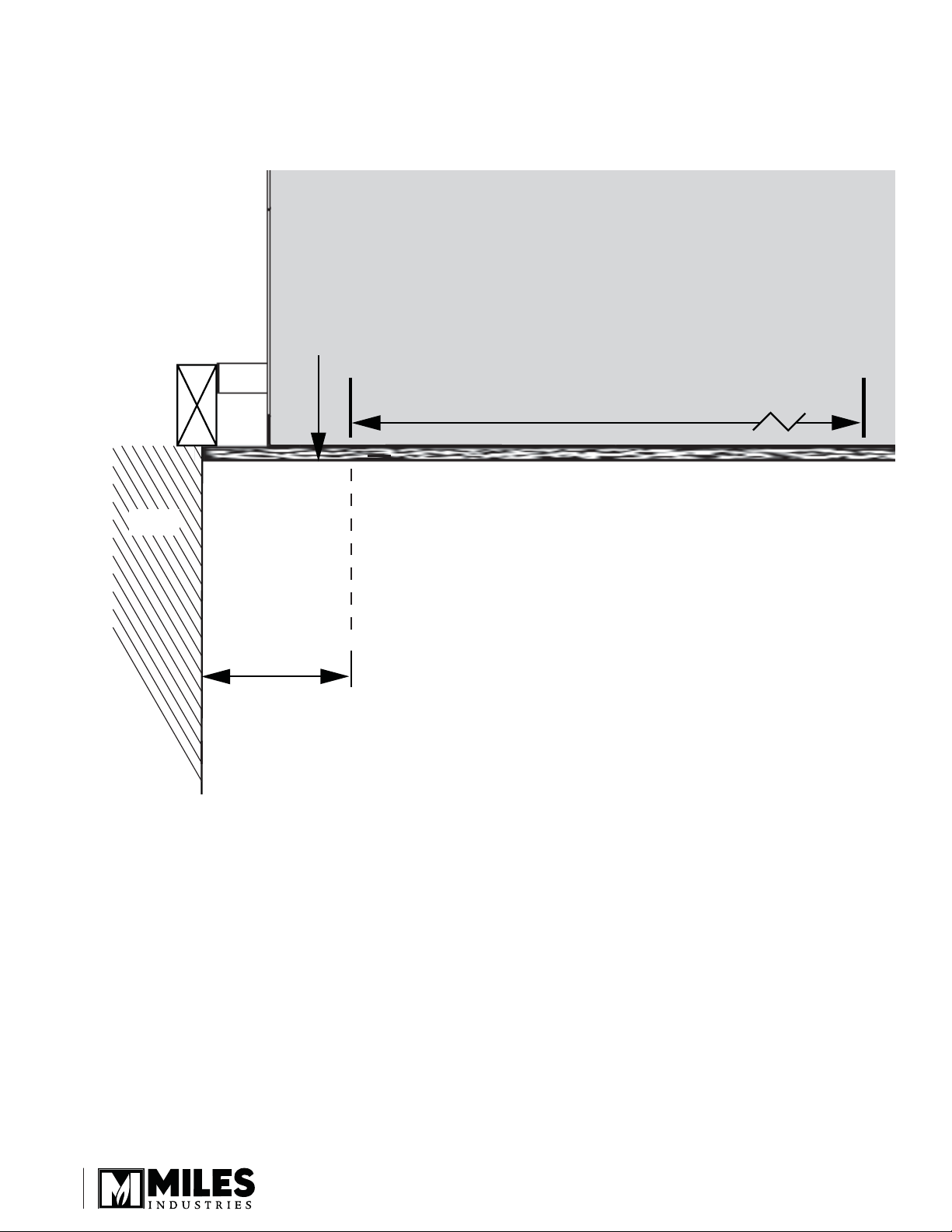
Mantel & Hearth Clearances
Combustible Mantel—Left Side View
Mantel Projection
(from Face of Cement Board)
0 2” 4” 6” 8” 10” 12”
Ceiling
44”
42”
40”
38”
Mantel
Height
(from
Bottom
of Unit)
24” Min. to Ceiling
Face of
Finished Wall
Fireplace
Opening
4” minimum to
combustible or
non-combustible hearth
33”
23-7/8”
Do not put
furniture or objects
within 36” (914 mm)
of front of appliance
9-3/8”
Bottom of Unit
11
Mantel & Hearth Clearances
Combustible Sidewall / Mantel Leg—Top View
Face of
Finished
Wall
FIREPLACE
Fireplace Opening
39-11/16”
Wall
Min. 4” to
wall or
combustible
mantel leg
12
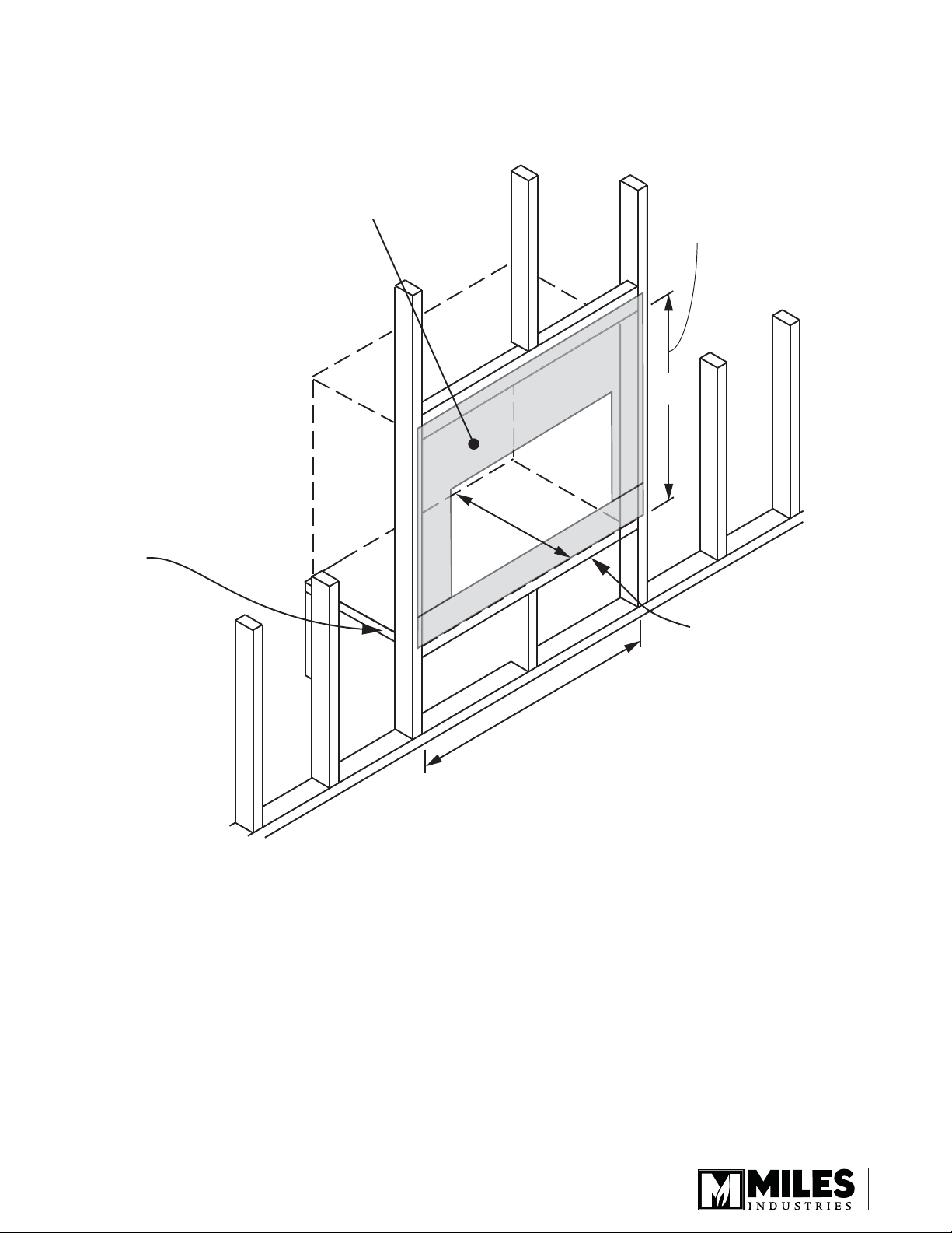
Framing Dimensions
1/2” thick cement board required
above, on each side and below
engine opening (supplied w/engine)
NOTE: This unit requires a
solid platform to support it.
Combustible framing allowed
beneath fireplace. When the
appliance is installed directly
on carpeting, tile or other
combustible material other
than wood flooring, the
appliance shall be installed
on a metal or wood panel
extending the full width
and recessed depth of the
appliance
Framing Requirements
Between underside
of header and bottom
of firebox
43”
20”
46”
No hearth required.
If using a hearth,
see page 11.
13
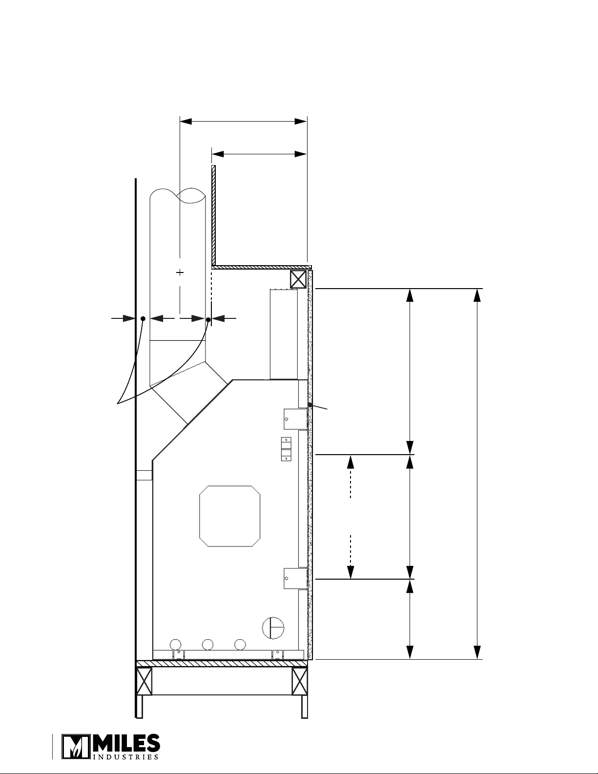
Framing Requirements
Framing with Partial Shelf—Vertical Vent
15-1/16”
(383 mm)
Approx. 10-3/4”
(274 mm)
from back
surface of
wall finish to
front surface
of appliance
case w/no
vent offset
Min. 1”
(25.4 mm)
clearance to
combustibles
around
vertical
vent pipe
Cement
Board
Fireplace
Opening
19-1/4”
(489 mm)
14-1/2”
(369 mm)
9-3/8”
(238 mm)
43” (1093 mm) to underside of combustible cavity
14
PARTIAL SHELF
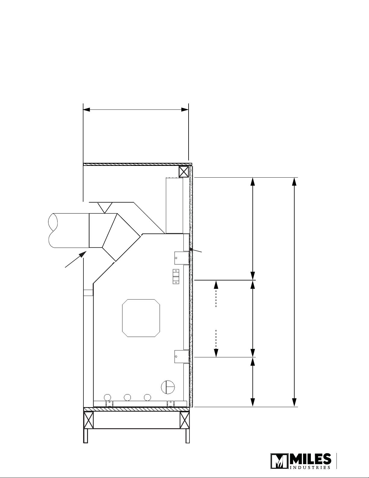
Framing Requirements
Framing with Full Shelf—Rear Vent
20” (508 mm)
from the front
surface of the
wall finish to the
front surface of
appliance case
For venting
clearances,
see Venting
Chart section
Cement
Board
Fireplace
Opening
19-1/4”
(489 mm)
14-1/2”
(369 mm)
9-3/8”
(238 mm)
43” (1093 mm) to underside of combustible cavity
FULL SHELF
15
Venting
Top or Rear Outlet
This unit is supplied with a top vent outlet which can
be fi eld-converted to a rear vent outlet. See Appliance
Preparation section for more information.
Vent Material
This unit is approved for installation using
4 x 6-5/8 inches co-axial direct vent pipe and
accessories as listed in the Approved Venting
Components section on pages 48–49 of this manual.
Follow the installation instructions supplied with the
individual venting accessories.
Wall Thickness
The appliance vent is suitable for penetrating a
combustible wall assembly up to 8 inches in thickness.
A non-combustible wall can be of any thickness up to
the maximum horizontal run of vent pipe allowed for the
particular installation.
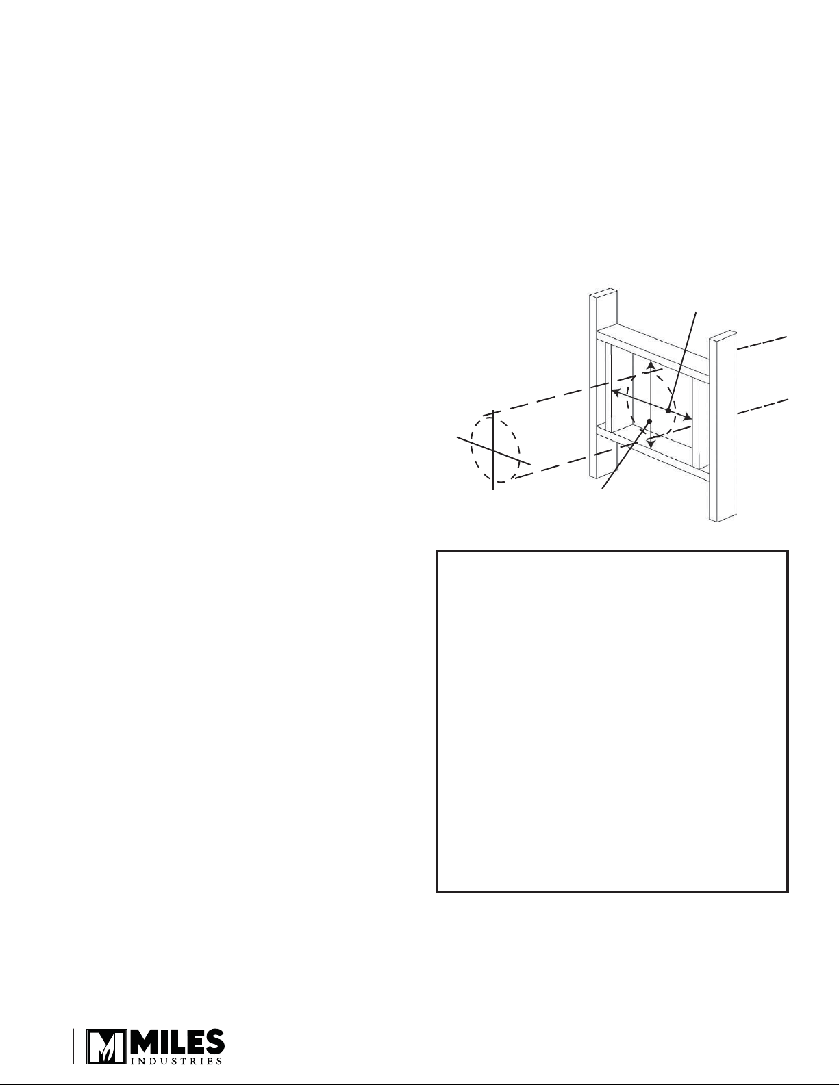
Framing Vent in Combustible Walls &
Ceilings
When penetrating through combustible walls and
ceilings, frame a minimum of 10 in x 10 in opening and
ensure that the insulation is kept clear of the vent pipe
using either a wall thimble or an attic insulation shield.
Follow the installation instructions supplied with the
individual venting components.
Align the vent
center to the
center of the frame
10” (254 mm)
10” (254 mm)
Important Installer Notice –
Weather Sealing & Vapor Barriers
It is the installer’s responsibility to ensure that vent
installations through exterior walls are caulked and
weatherproofed in such a manner as to:
• Prevent rain water from entering the wall from
the weather side by adequately caulking the
outer vent plate to the exterior wall surface.
• Prevent moisture inside the home from
penetrating into the wall structure by ensuring
the inside wall plate is adequately sealed to the
inside vapor barrier.
• Prevent rain water and moisture from entering
the walls by sealing the joints between the outer
vent tube and the inner and outer wall plates.
We recommend the use of a high quality
polyurethane sealant.
16
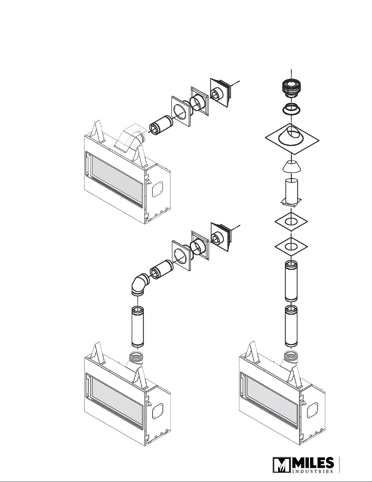
HORIZONTAL
TERMINATION
2-PIECE
WALL THIMBLE
PIPE
LENGTH
HORIZONTAL
TERMINATION
2-PIECE
WALL THIMBLE
PIPE
LENGTH
PIPE
LENGTH
PIPE
LENGTH
PIPE
LENGTH
90˚ ELBOW
CEILING
FIRESTOP
ATTIC
FIRESTOP
ATTIC
INSULATION
SHIELD
FLASHING
STORM
COLLAR
VERTICAL
TERMINATION
Typical Co-axial Venting Components
Venting
Rear Vent
Top Vent Top Vent
17
 Loading...