

Miles Industries 799EDF Installation Instructions Manual
Legend G4
799EDF Edgemont Door Front Kit
includes installations instructions for Valor 799BPB-1, 799BPB-2 and 799BPB-3
Use with Valor 780 and 785 Models only
Installation Instructions
!
A barrier designed to reduce the risk of burns from the hot
viewing glass is provided with this appliance and shall be
installed for the protection of children and other at-risk
individuals.
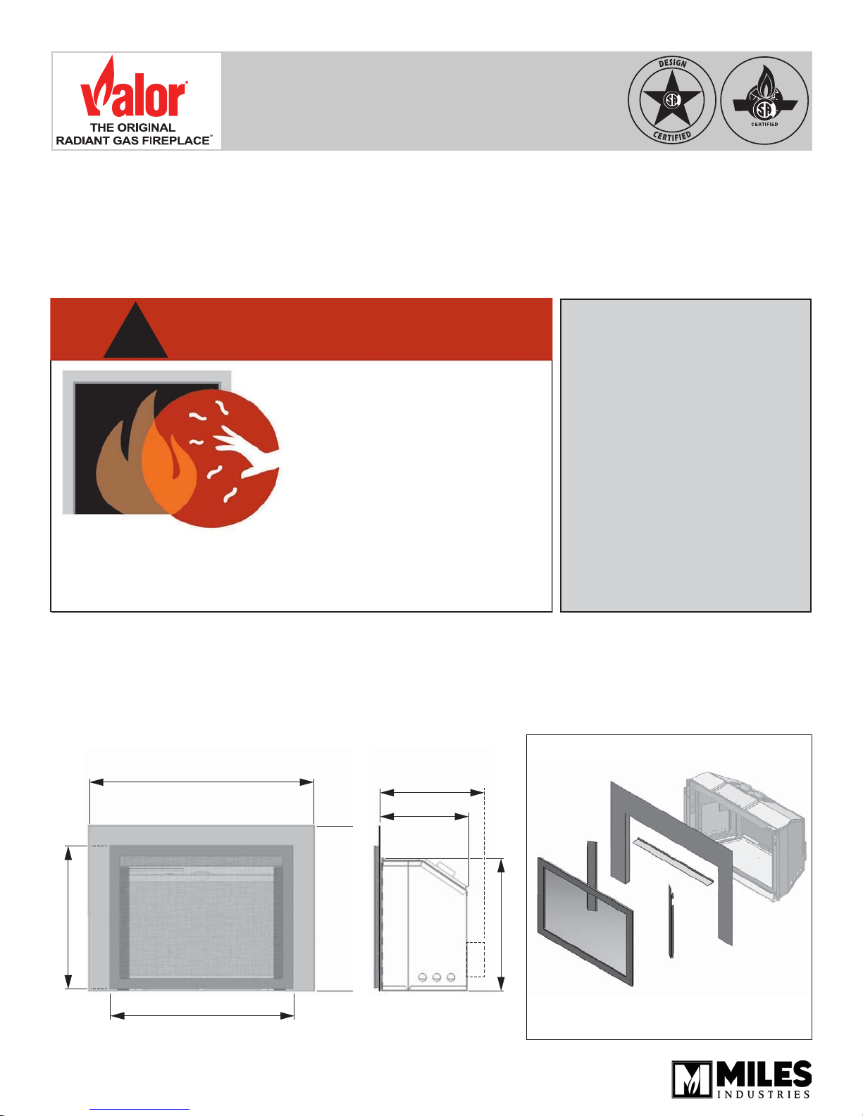
The 799EDF Edgemont Door Front Kit is intended to be used on
Valor heater model 780 & 785 with a required choice of Backing
Plate 799BPB-1, 799BPB-2 or 799BPB-3.
Mounting of the 799 aff ects cavity dimensions—see below and
installation manual supplied with the heater for more information.
Minimum Cavity Dimensions for 799
39.1/2” (1003 mm) 799BPB-1
46” (1168 mm) 799BPB-2
48” (1219 mm) 799BPB-3
DANGER
HOT GLASS WILL
CAUSE BURNS.
DO NOT TOUCH GLASS
UNTIL COOLED.
NEVER ALLOW CHILDREN
TO TOUCH GLASS.
Cavity Depth
19-3/4” (502 mm)
with fan
16-3/4”
(426 mm)
INSTALLER
Leave this manual
with the appliance.
CONSUMER
Retain this manual
for future reference.
G4 engine
Edgemont Door
24-3/4” (629 mm)
Cavity Width / Edgemont Door
35-3/4” (908 mm)
4005620-04
© Copyright Miles Industries Ltd., 2017
31” (787mm) 799BPB-2
32.3/8” (822mm) 799BPB-3
27” (686mm) 799BPB-1
Cavity Height
23-3/4” (603 mm)
799BPB
Sold seperately
799EDF
Including doors &
convection baffl e
Overview
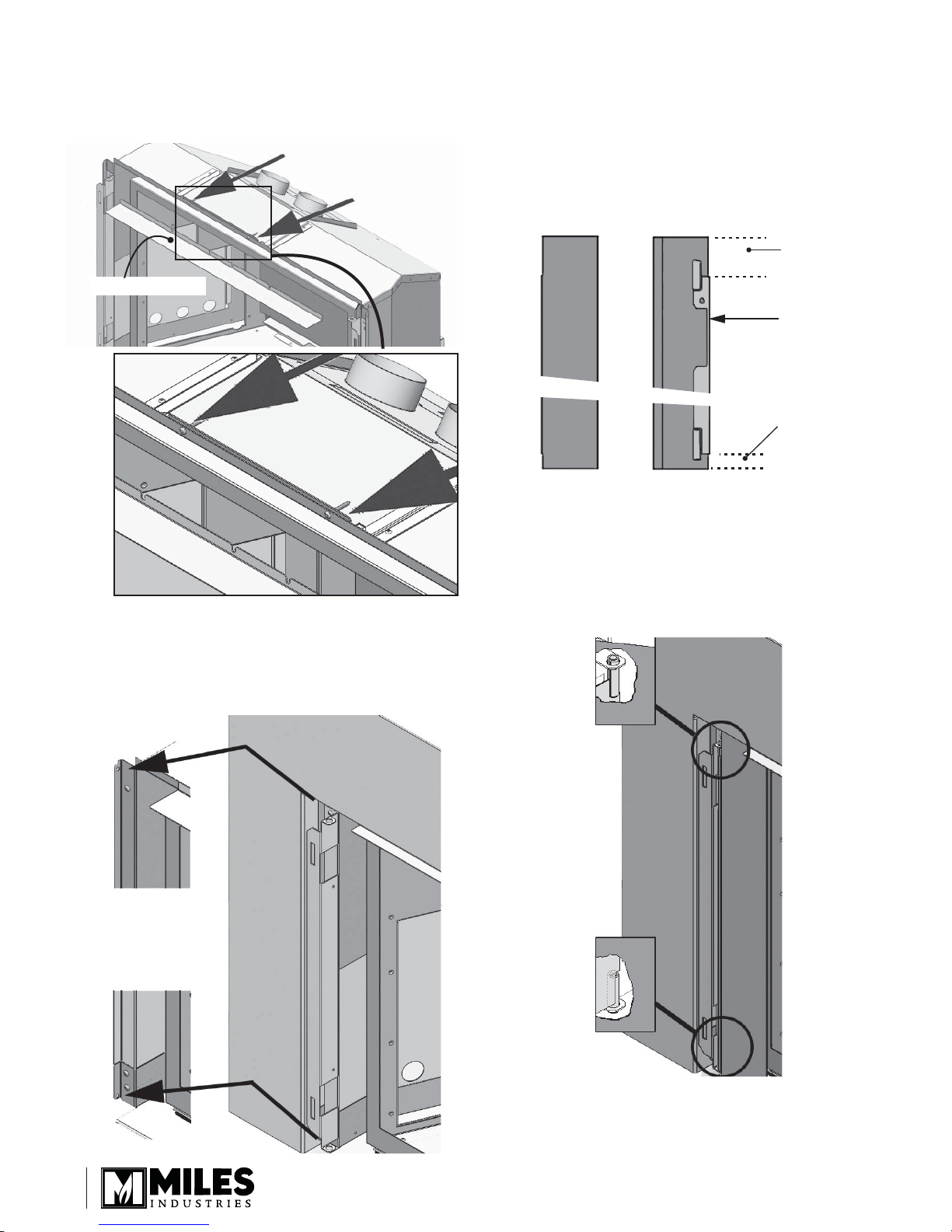
TOP of door:
this space is
wider
TOP of door:
notch in the
rear ange
Left door panel
Installation
BOTTOM of door:
this space is
narrower
Rear viewFront view
1. Back off both vent slide fi xing screws, locate
convection baffl e under screw heads and tighten
into place.
Back off vent slide screws
Convection baffl e
3. Identify the left and right door panels using the
image below.
4. Identify the top and bottom of the left panel. The
notch in the rear fl ange of the panel is at the top.
The space between the rear fl ange and the edge
of the panel is wider at the top than at the bottom
of the panel as shown below.
2. Secure the backing plate to the appliance’s outer
case from the inside as indicated (2 screws per
side).
Note: you may need to remove the side shrouds to
fi x the plate.
5. Insert the top pin of the left door panel in the hole
at the top of the left shroud already installed on the
appliance.
6. Lift the panel as far as possible and insert the
bottom pin in the hole at the bottom of the shroud.
The panel should rotate freely.
2
7. Install the right door panel the same way.
 Loading...