

Miles Industries 551DVK Installation Manual
Direct Vent Kit—Sidewall Terminal
551DVK
Installation Manual
CSA approved for use only with
Valor 530, 534, 535 and Miles Fireplace MF28
Model Heaters
Note: This kit must be installed or serviced by a qualied installer, service agency or
gas supplier. These instructions are to be used in conjunction with the main installation
instructions for the above listed heater models.
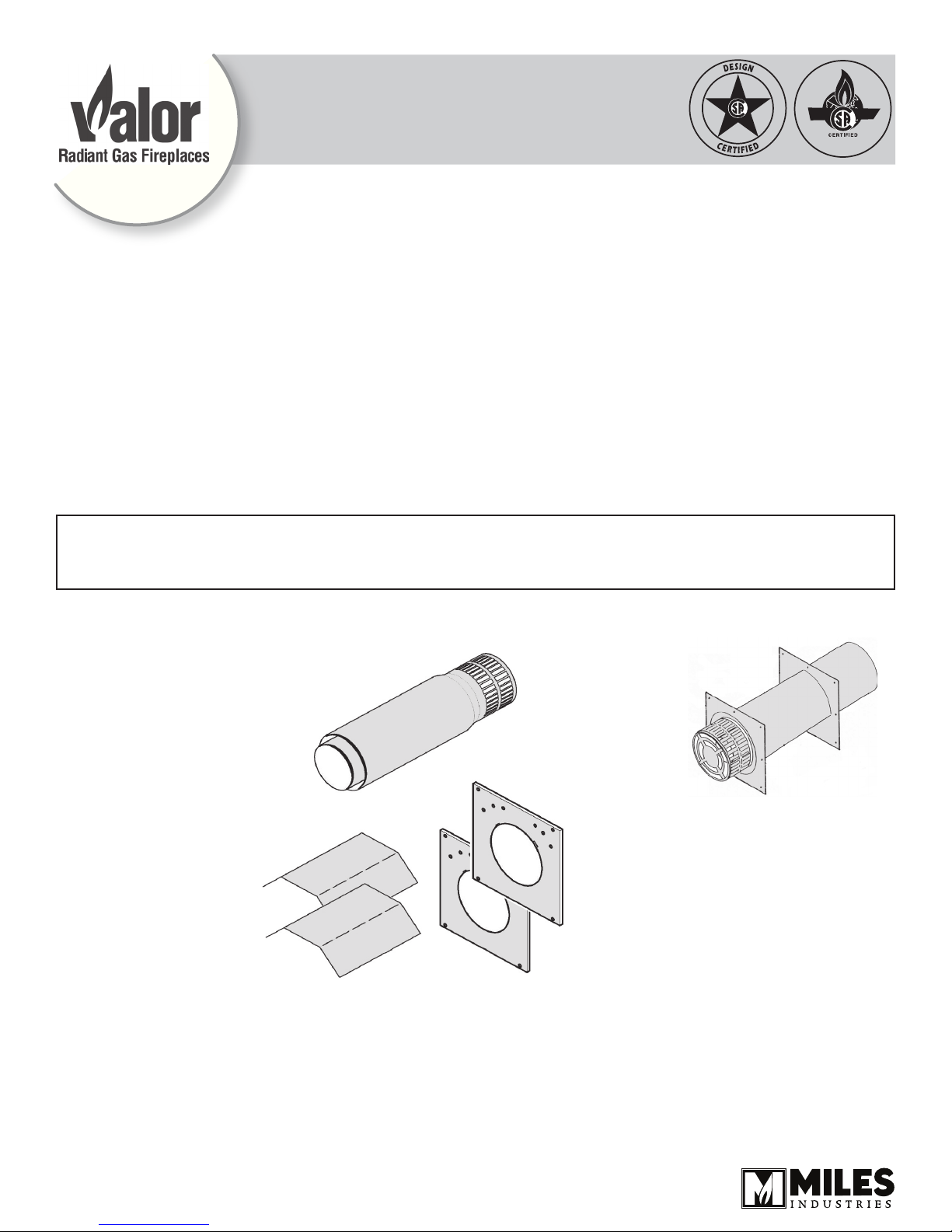
Kit Contents
1 Vent & Terminal
•
2 Wall Plates
•
2 Wall Shields
•
4001204-02
Designed and manufactured by / for
MILES INDUSTRIES LTD.
Columbie-Britannique, Canada
www.valorreplaces.com
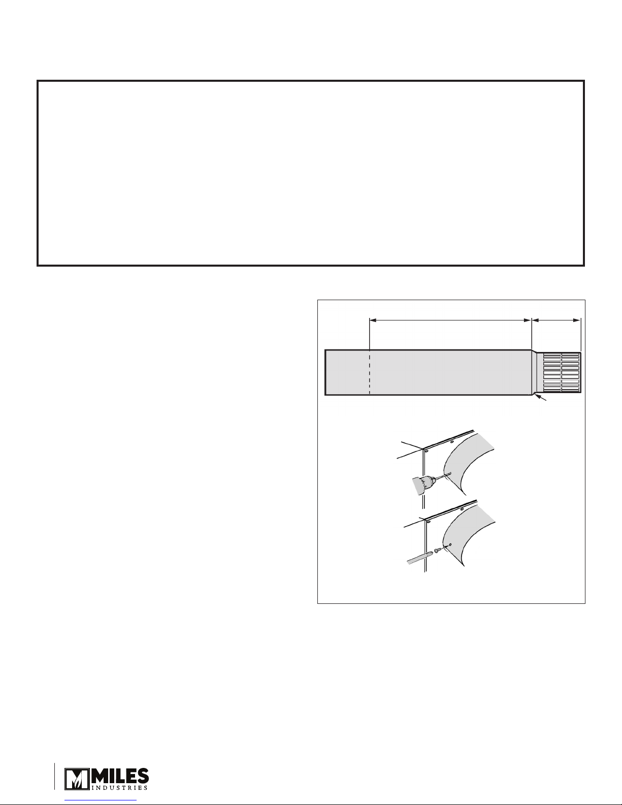
Installations with Horizontal Termination—Installing to Wall
Drain hole
This piece may be cut to length
Max. is 26”
5”
Important Installer Notice – Weather Sealing & Vapor Barriers
It is the installer’s responsibility to ensure that vent installations through exterior walls are caulked and weatherproofed in such a manner as to:
Prevent rain water from entering the wall from the weather side by adequately caulking the outer vent plate to
•
the exterior wall surface.
Prevent moisture inside the home from penetrating into the wall structure by ensuring the inside wall plate is
•
adequately sealed to the inside vapor barrier.
Prevent rain water and moisture from entering the walls by sealing the joints between the outer vent tube and
•
the inner and outer wall plates.
We recommend the use of a high quality polyurethane sealant.
See Location section in heater manual for full range of
horizontal termination applications.
Flat on Wall Installation
Cut the vent terminal pipe unit to size.
1.
Important! The drain hole must be clearly outside
the wall.
Measure the wall thickness.
a)
Add distance from case rear to wall.
b)
Measure this total length along the vent unit from
c)
where the termination cap joins the main terminal
pipes. Mark the unit.
Insert the Styrofoam support ring and push it as
d)
close as possible to the marked position.
Cut the vent tubes squarely to length.
e)
Make sure that all Styrofoam is removed from
f)
the vent unit after cutting.
Free the appliance from the frame studding and slide
2.
the appliance forward to allow the terminal to be tted.
Fit the vent unit fully over the appliance inlet and outlet
3.
collars pushing on rmly. Make sure that the drain hole
is at the bottom—the seam will be through the notch in
the wall plates. See gure 34.
Drill through the terminal outer tube and appliance
4.
outer collar for #6 screws. See gure 1. Make sure
that the drill does not penetrate the inner tubes.
Secure the terminal to the outer collar with two #6
5.
thread-cutting screws supplied. See gure 1.
Figure 1
22
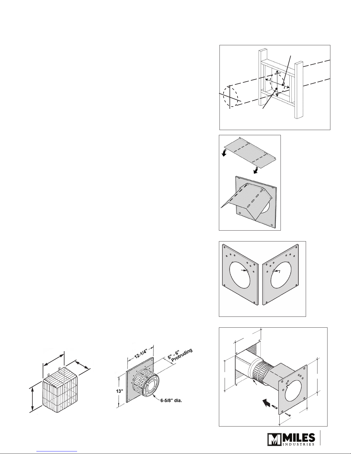
13”
12-1/4”
10”
10”
Drain hole
Installations with Horizontal Termination—Installing to Wall
13-1/4”
8”
16-3/4”
Bend
this tab
towards
wall
Bend
this tab
towards
wall
Inside Wall Plate
Outside Wall Plate
Wall Opening
•
Where applicable, t all the required pipes and elbows up to the
wall. See the manufacturer’s instructions supplied with the venting
sections.
Check the wall opening position.
•
Make wall opening.
•
If the wall is constructed of solid non-combustible materials and has
no combustible surface cladding (including wood) inside or outside,
the wall plates or thimbles will not be required.
If the wall has combustible material, mark the wall for a 10” x 10”
square. If the wall is totally non-combustible (e.g. masonry block or
concrete), mark for a 7” circular hole. In both cases, the center of the
hole should line up with the center line of the horizontal vent.
Preparing Wall Plates
The wall plates are not used for 7” hole in non-combustible walls.
Bend the wall shields and screw to the inside of the wall plates with
1.
6 thread-cutting screws per plate. See gure 2.
Bend the inner wall plate tab as shown in gure 3 so that the seam
2.
on the terminal tube will pass clearly through the plate with the wall
shield at the top. Place the inner wall plate over the terminal unit.
Slide the appliance/terminal into the wall. Make sure that the drain
3.
hole is at the bottom—the seam will be through the notch in the wall
plates. See gure 4.
Slide the inner wall plate up to the wall. Mark the four holes for the
4.
wall screws. Slide the plate away.
Drill and plug the wall.
5.
Screw the plate to the wall with four screws provided.
6.
Bend the outer wall plate tab as shown in gure 4.
7.
Place the outer wall plate over the terminal unit. Slide the wall plate
8.
up to the wall. Mark the four holes for the wall screws. Slide the
plate away.
Drill and plug the wall.
9.
Screw the plate to the wall with four screws provided. See gure 4.
10.
Re-position the appliance so that it is suitable for the wall nish.
11.
Align the vent
center to the
center of the
frame
10” (254 mm)
Square opening
Figure 2
10” (254 mm)
Terminals—Installing to Wall
Unless the wall is totally non-combustible, t wall thimbles. Install as
detailed in the manufacturer’s instructions supplied with the pipes.
Sidewall vent terminations within 7’ of grade require a terminal
guard when used with a 551DVK. See gure 3a.
Figure 3a Terminal Guard Figure 3b Terminal
Figure 3
Figure 4
33
 Loading...