

Miles Industries 530XAN, 530XAP, 530XCN, 530XCP Owner's Manual
Model 530XAN/XAP
Model 530XCN/XCP
Direct Vent Gas Fireplace Heater
(With Logs or Coals)
Installation and Owner’s Manual
Please read this manual before installing and operating this heater
This manual should remain with the homeowner
- Do not store or use gasoline or other
flammable vapors and liquids in the
vicinity of this or any other appliance.
-WHAT TO DO IF YOU SMELL GAS
• Do not try to light any appliance.
• Do not touch any electrical switch: do
not use any phone in your building.
• Immediately call your gas supplier from
a neighbor’s phone. Follow the gas
supplier’s instructions.
• If you cannot reach your gas supplier,
call the fire department.
- Installation and service must be
performed by a qualified installer,
service agency or the gas supplier.
This appliance may be installed in an
aftermarket permanently located,
manufactured (mobile) home, where not
prohibited by local codes.
WARNING: If the information in
these instructions is not followed
exactly, a fire or explosion may result
causing property damage, personal
injury or loss of life.
This appliance is only for use with the
type of gas indicated on the rating plate.
This appliance is not convertible for use
with other gases, unless a certified kit is
used.
This appliance is a domestic room-heating
appliance. It must not be used for any
other purpose such as drying clothes etc.
B-Vent Installations
If this appliance is intended to be installed
with a B-Vent instead of direct vent, discard
this manual. Follow the installation and
operating procedure in the manual supplied
with the B-Vent adapter kit #552BVK.
This appliance is suitable for installation in a
bedroom or bed sitting room.
Massachusetts: the piping and the final
gas connection must be performed by a
licensed plumber or gas fitter in the State
of Massachusetts
Manufactured by
MILES INDUSTRIES LTD.
British Columbia, Canada
Vous pouvez vous procurer un exemplaire en langue Française de cette brochure chez votre marchand.
4000305/04

2 of 48
CONTENTS
1. SAFETY INFORMATION.....................................................................................................................................................................3
2. OPTIONS .................................................................................................................................................................................................. 4
2.1 Appliance styles................................................................................................................................................................................ 4
2.2 Additional optional features......................................................................................................................................................... 4
2.3 LP Gas................................................................................................................................................................................................ 4
2.4 Venting options................................................................................................................................................................................ 4
3. GENERAL.................................................................................................................................................................................................. 7
3.1 Approvals & codes ........................................................................................................................................................................... 7
3.2 Ratings................................................................................................................................................................................................ 7
3.3 Wall Thickness ................................................................................................................................................................................ 7
3.4 Supply Gas 7
3.5 Controls ............................................................................................................................................................................................. 7
3.6 Electrical............................................................................................................................................................................................ 7
4. LOCATION – PRESIDENT FS............................................................................................................................................................ 8
4.1 Wall & Floor Fixing ......................................................................................................................................................................... 8
4.2 Venting configurations...................................................................................................................................................................8
5. LOCATION – ZERO CLEARANCE ................................................................................................................................................ 15
5.1 Framing General............................................................................................................................................................................ 15
5.2 Finishing General............................................................................................................................................................................. 15
5.3 President 536/ Bolero 541 Fronts 15
5.4 Windsor Arch 539 Front 16
5.5 Z.C Venting Configurations ....................................................................................................................................................... 17
6. RECESSED INSERT APPLICATIONS........................................................................................................................................... 23
7.
DIRECT VENT TERMINAL LOCATION .......................................................................................................................................... 24
8. HEATER PACK CONTENTS 25
9. HEATER PREPARTION.....................................................................................................................................................................26
9.1 Detach the window ....................................................................................................................................................................... 26
9.2 Check ignition spark..................................................................................................................................................................... 26
9.3 Burner Module Removal ............................................................................................................................................................. 26
9.4 Conversion to Top Outlet........................................................................................................................................................... 27
9.5 Rear Outlet Preparation.............................................................................................................................................................. 28
9.6 DuraVent Co-Linear.....................................................................................................................................................................28
9.7 Valor 556 CLA Co-Linear Adapter............................................................................................................................................ 28
9.8 Air Restrictor.................................................................................................................................................................................. 29
10. INSTALLING HORIZONTAL TERMINATION. .......................................................................................................................30
11. INSTALLING ROOF TERMINATION..........................................................................................................................................32
12. REMOTE CONTROL INSTALLATION....................................................................................................................................... 33
13. GAS SUPPLY INSTALLATION....................................................................................................................................................... 34
14. AERATION SETTING CHECK ....................................................................................................................................................... 35
15. CERAMIC FUEL BED INSTALLATION....................................................................................................................................... 35
15.1 Ceramic Walls Installation.......................................................................................................................................................... 35
15.2 Ceramic Log Installation............................................................................................................................................................. 36
15.3 Ceramic Coals Installation..........................................................................................................................................................37
16. WINDOW REFITTING & CHECKING..........................................................................................................................................38
17. OPERATION CHECKS....................................................................................................................................................................... 38
18. INSTALLATION OF FRONTS AND COMPONENTS 39
18.1 President 531 Free Standing Front 39
18.2 President 536/Bolero 541 Z.C Fronts 40
18.3 Windsor Arch 539/549 Fronts..........................................................................................................................................................42
19. OWNERS INFORMATION................................................................................................................................................................ 44
19.1 Operating Your Fire
19.2 Operating remote control ........................................................................................................................................................... 44
19.3 Cleaning........................................................................................................................................................................................... 45
19.4 Checks.............................................................................................................................................................................................. 47
19.5 Servicing.......................................................................................................................................................................................... 47
19.6 General servicing
20. WARRANTY............................................................................................................................................................................................ 48
3 of 48
1.0 SAFETY INFORMATION
WARNING: Do not operate the appliance with the
glass front removed, cracked or broken.
Replacement of the glass should be done by a
licensed or qualified service person.
(The whole window unit may be temporarily
removed by the owner for cleaning the interior of
the firebox, etc.)
Only the authorized Valor replacement window
unit listed in the repair parts booklet must be
fitted - never use substitutes.
If the glass is damaged search inside and adjacent
to the appliance for any glass fragments.
Due to high temperatures, the appliance should be
located out of traffic and away from furniture and
draperies.
Children and adults should be alerted to the
hazards of high surface temperatures and should
stay away to avoid burns or clothing ignition.
Young children should be carefully supervised
when they are in the same room as the appliance.
Clothing or other flammable material should not
be placed on or near the appliance.
This appliance must be installed and repaired b y a
qualified service person. The appliance should be
inspected before use and at least annually by a
professional service person. More frequent
cleaning may be required due to excessive lint
from carpeting, bedding material, etc. It is
imperative that control compartments; burners
and circulating air passageways of the appliance
are kept clean.
Keep curtains, clothing, furniture and other
flammable materials a safe distance from all parts
of the appliance and its vent system.
Keep the appliance area well clear and free from
combustible materials, gasoline and other
flammable vapors and liquids.
Never attempt to burn paper or any other material
in the appliance.
The venting terminal must not be recessed into a
wall or siding.
The vent terminal on the outside wall must be
kept free from obstructions. No objects should be
placed within 2 feet (60cm) of the vent terminal.
The terminal is hot during operation and requires
a guard if it is accessible to any person. An
approved Valor guard is available from your
dealer.
During extreme weather conditions ensure that
the vent outlet is free from ice and snow before
attempting to light.
Do not use this appliance if any part has been
under water. Immediately call a qualified service
technician to inspect the appliance and to replace
any part of the control system and any gas control,
which has been under water.
NOTE
When operating your new fireplace for the first time, some vapors may be released due to the burning of curing
compounds used in the manufacture of the appliance. They may cause a slight odor and could cause the flames to be the
full height of the firebox, or even slightly higher, for the first few hours of operation. It is also possible that these vapors
could set off any smoke detection alarms in the immediate vicinity. These vapors are quite normal on new appliances and
are totally harmless. After a few hours use the vapors will have disappeared and the flames will be at their normal height.
During the first hour of use the ceramic firebox walls may go a smoky color. This is not soot. It is a temporary effect
lasting only while the ceramic material becomes stabilized. The walls will revert to their initial color after your fire has
been used for one or two hours.

4 of 48
2.0 OPTIONS
Heater engine unit # 530 X is available in either natural
gas or LPG and comes equipped with either a simulated
log or coal fuel bed in either fuel. The 530X engine unit
is supplied standard with a rear vent D.V outlet and may
be converted to a top outlet D.V with no extra parts
required. The engine is not supplied suitable for zero
clearance, the parts required to make the engine zero
clearance are supplied with the various front trims
(except 549 front)
2.1 Appliance styles
President FS 531 Free standing cast iron stove.
(See figure 1).
President 536 For recessed application, either zero
clearance or insert . (See figure 2)
Windsor Arch 539/549 Arched Cast Iron Front for
recessed application, either zero
clearance(see fig 3) or insert (see fig
4). (549 version is insert only )
Bolero 541 Contemporary cast iron front for
recessed application, either zero
clearance or insert (see fig 5).
One of the above kits must be used with each installation.
2.2 Additional optional features
Circulating Fan Kit #555CFK Having variable speed
and temperature control, it is
designed to boost the natural
convection process through
the appliance. It may be fitted
before the fireplace is installed
or retrofitted at a later date.
Closure Plate #3336 CP 33” high x 36” wide black
closure plate with black aluminum extrusion edge. To
cover openings for insert applications.
2.3 LP Gas
LPG Conversion kit Burner & injector kit for
conversion from natural gas to
propane – Kit #554LPK.
2.4 Venting options
2.4.1 Direct vent installations (solid
piping)
One or more of the accessories listed below must be
used for each installation. See the “Location” section of
this manual.
Kit#
551DVK Valor Horizontal terminal kit with pipe
section. Maximum useable length 26”.
(66cm) (Maximum 14” thru combustible
wall section (36cm)
556 CLA Co-Linear appliance Adapter
558FLK Through the wall Dura-vent pipe
insulation kit
817VAK Adapter for Dura-vent pipes
984 Dura-vent DV GS horizontal square
terminal cap
942 Dura-vent DV GS wall thimble kit
945B 45° Dura-vent DV GS elbow
990B 90° Dura-vent DV GS elbow
908B 6” Dura-vent DV GS pipe length
907B 9” Dura-vent DV GS pipe length
906B 12” Dura-vent DV GS pipe length
904B 24” Dura-vent DV GS pipe length
903B 36” Dura-vent DV GS pipe length
902B 48” Dura-vent DV GS pipe length
911B Adjustable 11”-14
5
/8” Dura-vent DV GS
pipe length
981 Dura-vent DV GS snorkel termination
unit – 36” rise
982 Dura-vent DV GS snorkel termination
unit – 14” rise
980 Dura-vent DV GS Low Profile vertical
termination cap
991 Dura-vent DV GS high wind vertical
termination cap
940 Dura-vent DV GS round ceiling support
941 Dura-vent DV GS cathedral ceiling
support box
963 Dura-vent DV GS ceiling firestop
943 Dura-vent DV GS adjustable roof
flashing. Roof pitch 0/12 – 6/12
943S Dura-vent DV GS steep roof flashing.
Roof pitch 7/12 – 12/12
953 Dura-vent DV GS storm collar
988 Dura-vent DV GS wall strap
923GCL Dura-vent DV GS co-axial to co-linear
appliance connector
923GK Dura-vent DV GS co-linear termination
kit
984 Dura-vent DV GS square terminal cap
2280 Dura-vent DV GS co-linear flex
chimney liner 35ft. length.
835TG Terminal Guard
2.4.2 Direct Vent Co-Linear Installations –
for Free Standing or Recessed
Installations (flexible piping)
Converts the appliance outlet collars to accept
two 3” dia. Flex liners for installation into
existing solid fuel burning fireplaces and
chimneys. Requires 556 CLA adapter and 923
GK termination kit along with either a 980 or
991 termination cap.( 923GCL may be used in
lieu of 556 CLA adapter)
2.4.3 B-vent installations – For President
Free Standing only
Kit #552BVX converts this appliance from a
direct vent fireplace heater to a gravity vent
fireplace heater for use with a 4” “B” type vent.
A full installation and operating manual is
supplied with the kit.
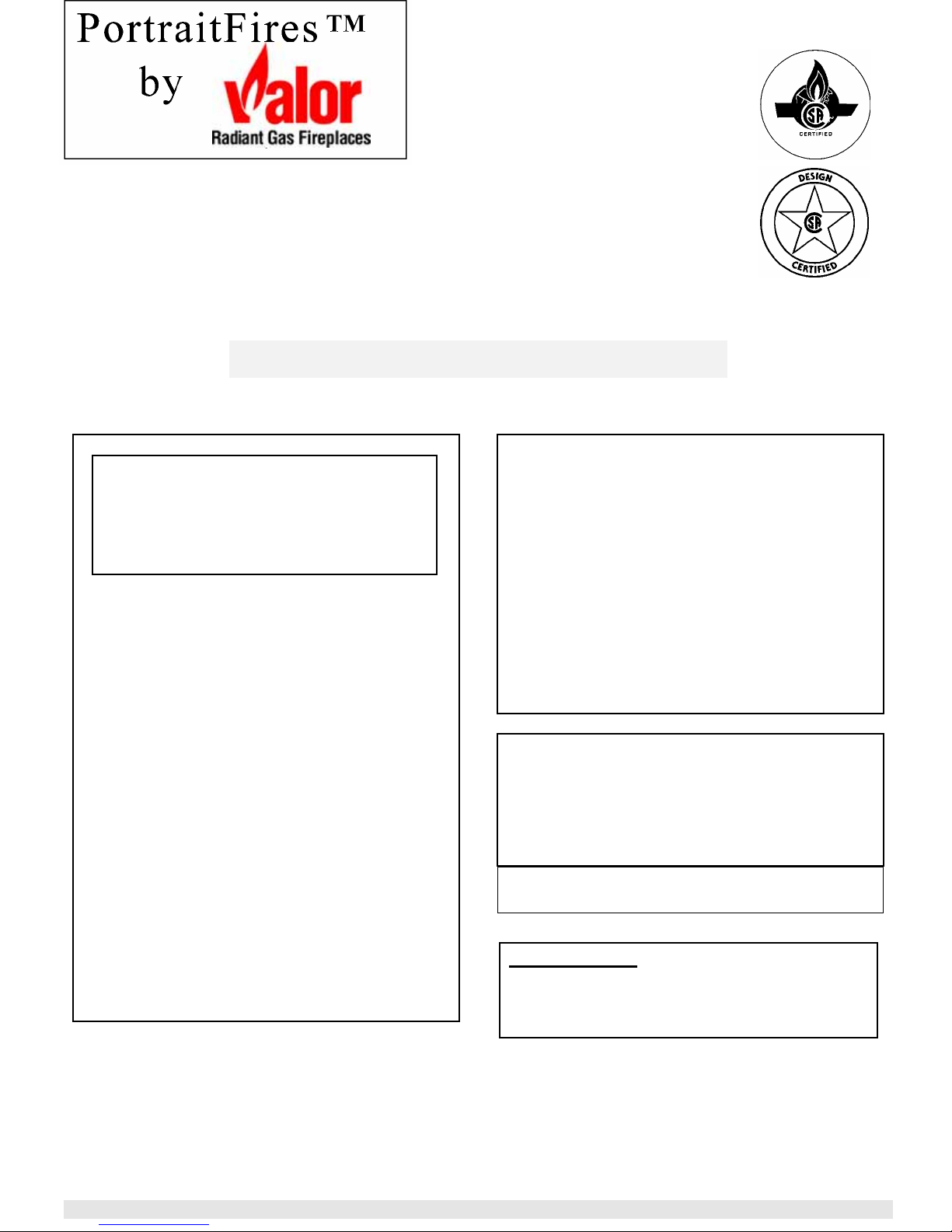
5 of 48
Figure 1. Model 531 President Free Standing – Dimensions
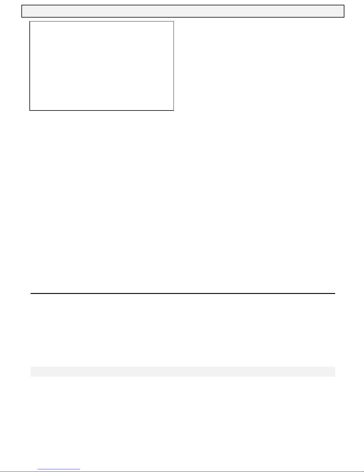
Figure 2. Model 536 Recessed President – Dimensions
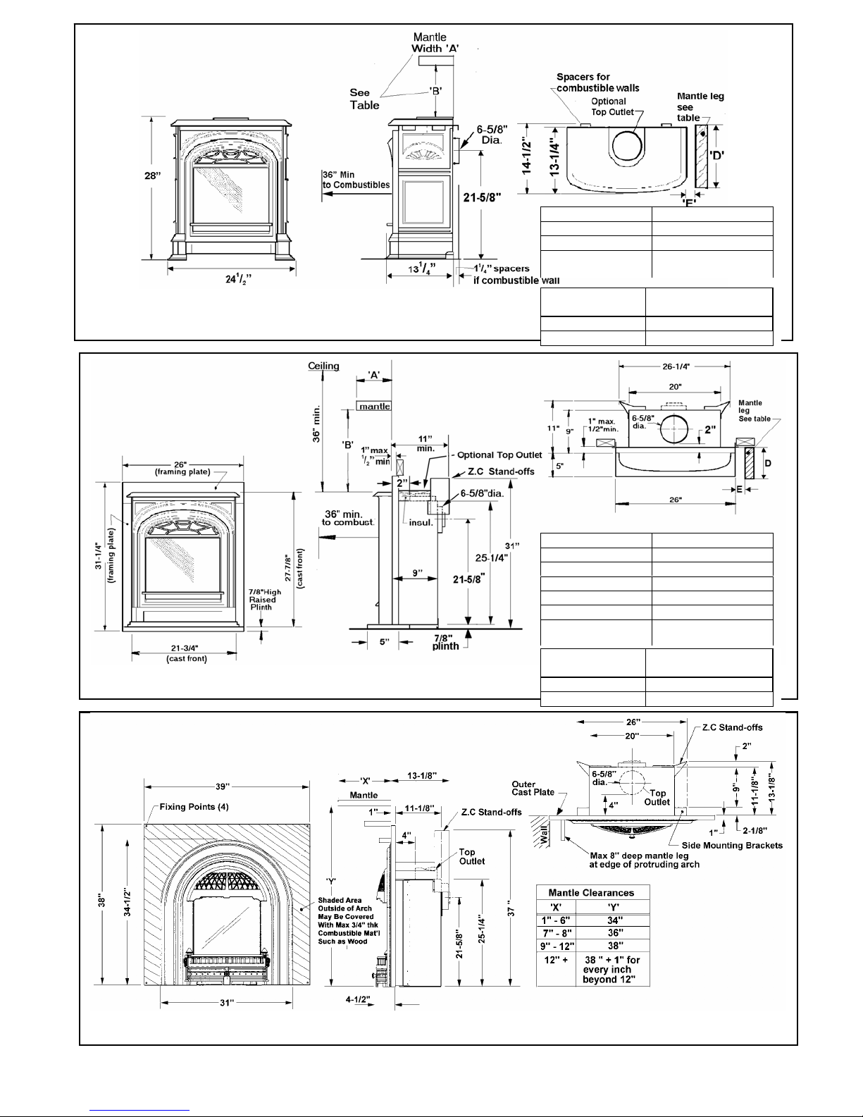
Figure 3. Model 539 Windsor Arch. with Backplate - Dimensions
Mantle depth “A” Min. Clearance“B”
Up to 7” 4”
Above 7” up to 8” 5”
Above 8” up to 9” 7”
Above 9” up to10” 8”
Above 10” up to 12” 9”
More than 12” 9”+extra 1” for every
1” de
p
th above 12”
Mantle leg
projection “D”
Min clearance from
appliance side “E”
Up to 8” 0”
More than 8” 6”
Mantle depth “A” Min. Clearance“B”
Up to 12” 4”
Above 12” up to 18” 8”
More than 18” 8”+extra 1” for every
1” de
p
th above 18”
Mantle leg
projection “D”
Min clearance from
appliance side “E”
Up to 8” 1”
More than 8” 6”
6 of 48
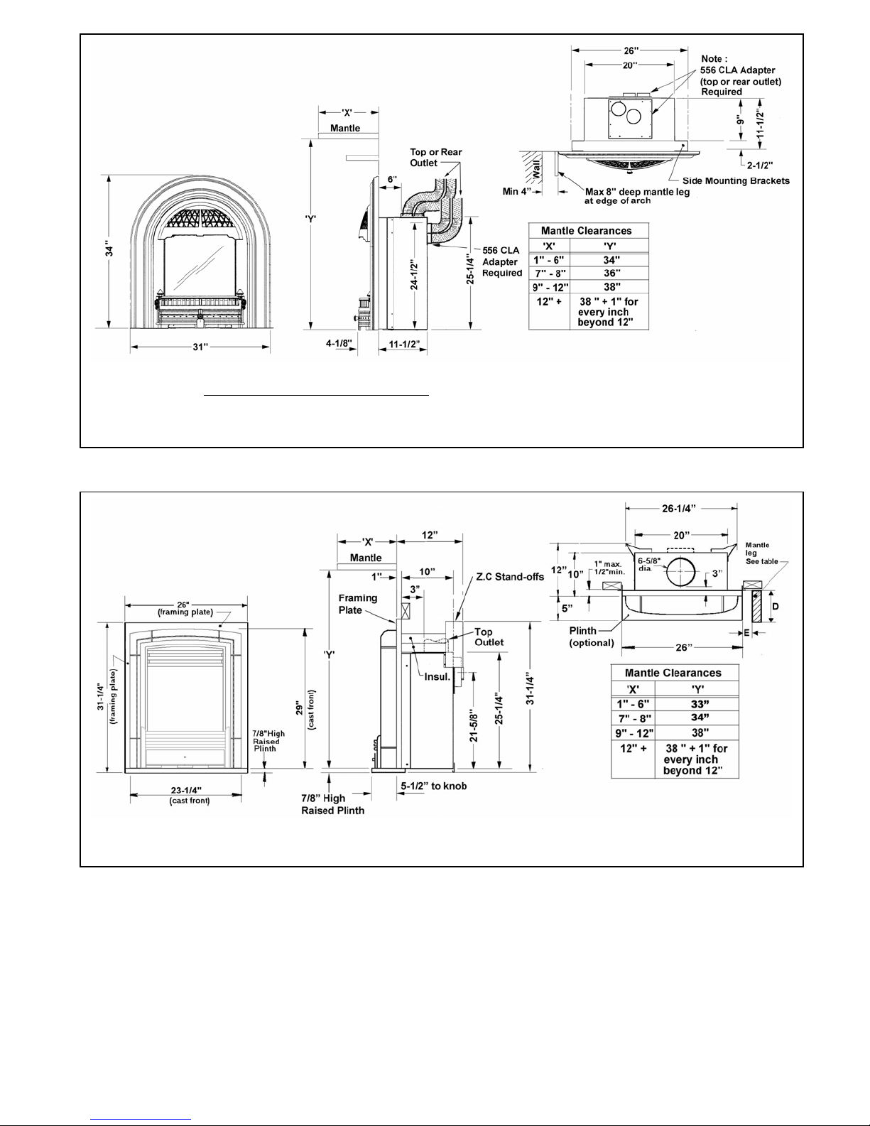
Fig 4. 549 Windsor Arch without backplate.
Note – this option
is intended for insert applications only and does not include the stand-offs and insulation pads
required for zero clearance applications. Most recessed 530 insert applications will also require a 556 CLA co-linear
adapter
Fig 5. - 541 Recessed Bolero Dimensions
7 of 48
3.0 GENERAL
3.1 Approvals & codes
This appliance is certified by International Approval Services for use in Canada and the USA.
The appliance complies with CGA P.4.1, Testing method for measuring annual fireplace efficiencies.
The installation must conform with local codes or, in the absence of local codes with the National Fuel Gas Code, ANSI
Z223.1or the Canadian installation code CAN/CGA-149. Only qualified licensed or trained personnel should install the
appliance.
The appliance, when installed, must be electrically grounded in accordance with local codes or, in the absence of local
codes, with the National Electrical Code, ANSI/NFPA 70 or the Canadian Electrical Code, CSA C22.1.
3.2 Ratings
Nat. Gas LPG
Altitude (Ft) 0-4500 *
Input Max. (Btu/h) 20,500 19,000
Input Min (Btu/h) 6,000 11,600
Manifold pressure (in.w.c.) 3.5 – 3.9 10.3 – 10.7
Min. Supply pressure (in. w.c.) 5.0 11.0
Max. Supply pressure (in. w.c.) 10.5 14.0
*Tested to CAN/CGA - 2.17 Gas fired appliances for use at high altitudes. In the USA installations may require deration over
2000ft - Check local codes.
3.3 Wall Thickness
The appliance vent is suitable for penetrating a combustible wall up to 14” (36cm) thick.
A non-combustible wall can be any thickness up to the maximum horizontal run of vent pipe allowed for the particular
installation – See sections 4 and 5.
3.4 Supply Gas
Heater engine 530XAN /XCN is used on Natural gas installations.
Heater engine 530XAP/XCP is used on Propane installations.
The supply pressure must be between the limits shown in section 3.2 above.
The supply connection is
3
/8’’NPT.
The opening for the gas supply line is at the rear left corner of the appliance.
3.5 Controls
The unit is supplied standard with a battery operated, hand held remote control and receiver which has the ability to adjust
the gas input of the unit between the pilot setting and the maximum input .The pilot light must be manually lit at the valve
and may be left on or turned off with each use. The remote control provides full thermostatic or manual operation with
the option of programming thermostat function between certain times of the day. Manual operation of the valve is also
possible should the batteries or remote control fail.
3.6 Electrical
The unit does not require an electrical power source unless fitted with an optional circulating fan.
8 of 48
4.0 LOCATION – PRESIDENT FREE STANDING
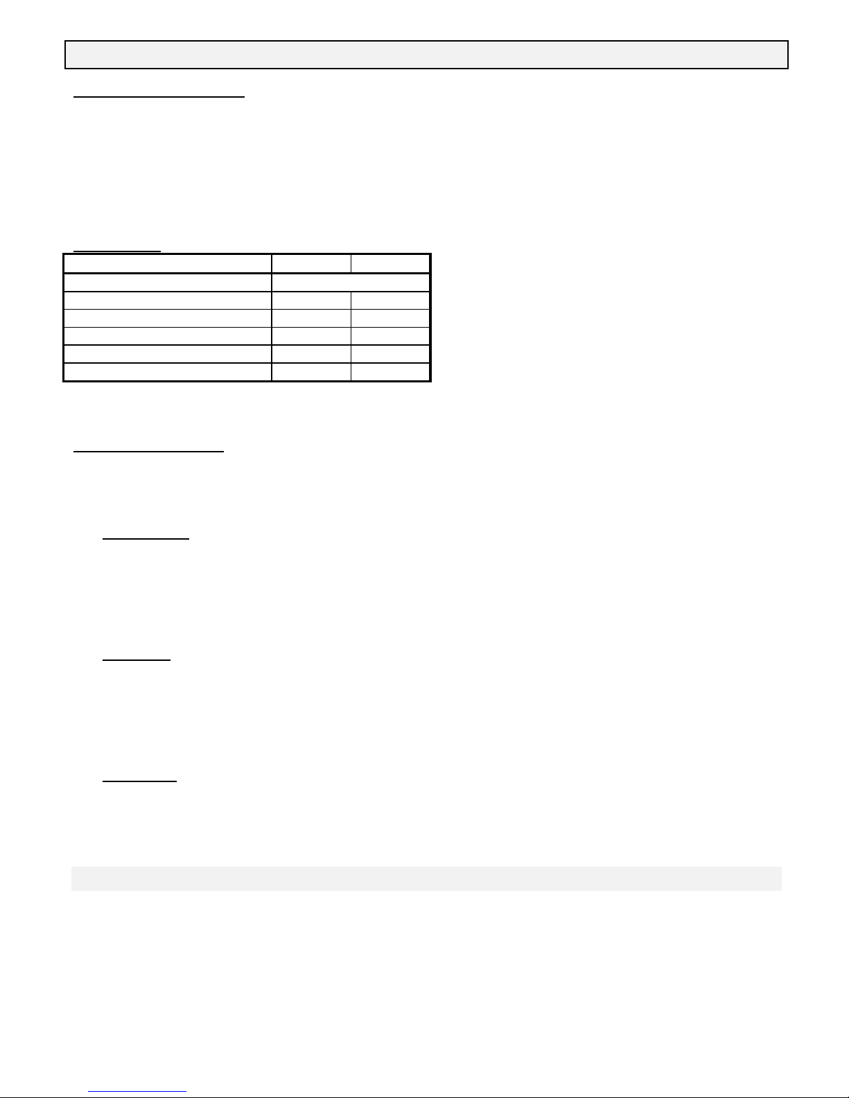
4.1 Wall & Floor Fixing
Figure 6 President FS fixing holes
The President FS can be installed against a wall or in the
room away from walls. The appliance is designed to be fixed
to the floor. The appliance can additionally or alternatively
be fixed to a rear wall. The fixing positions are shown in
figure 6. The appliance is approved for installation directly
on wood flooring. If the appliance is installed directly on
carpeting, vinyl tile or other combustible material other than
wood flooring, it must be installed on a metal or wood panel
extending the full width and depth of the appliance.
4.2 Venting configurations
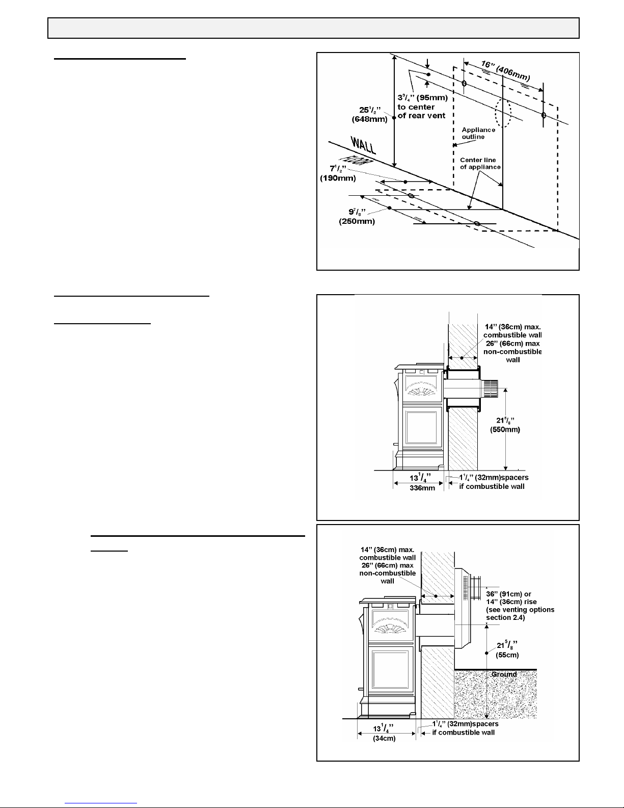
4.2.1 Flat on wall
Requires Valor vent kit #551DVK or Dura-vent pipe length
with adapter #817VAK and Dura-vent terminal cap.
The location requirements are shown in figure 7.
The horizontal vent run cannot be extended beyond the dimensions
shown in figure 5 by the use of any vent accessory pipes.
4.2.2 Flat on wall with snorkel termination
(Fig.8)
Figure 8
Figure 7
For use on horizontal vent installations where the outside
ground level is too close to the standard terminal. Adapter
#817VAK, a Dura-vent pipe length and snorkel termination
#981 or #982 will be required (See vent options section of
this manual).
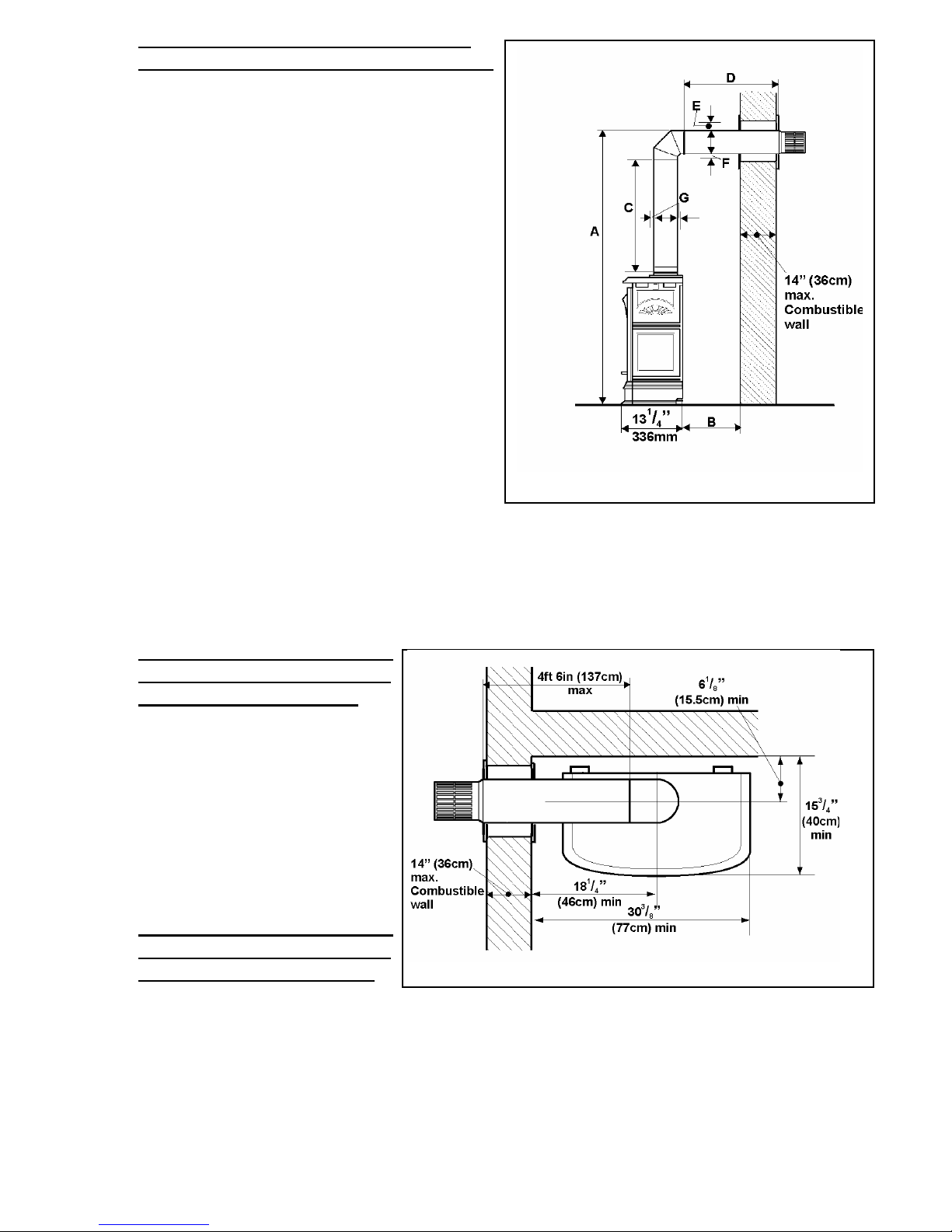
4.2.3
9 of 48
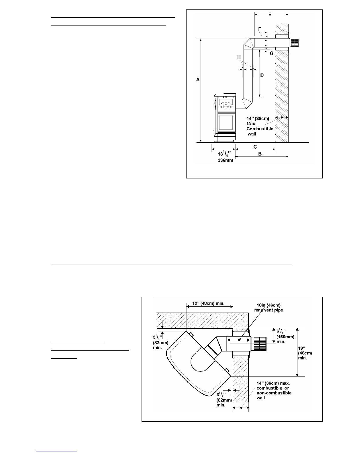
Rear vent connection, vertical vent rise
with horizontal termination (Fig. 9)
Can be used with either #551DVK standard vent kit or #984
Dura-vent terminal cap and accessories.
Adapter #817VAK, two 90° vent elbows #990B and Dura-vent
pipe lengths will be required.
(See venting options section of this manual).
No more than two 90°elbows must be used.
Minimum Maximum
A: From floor to top
of vent duct
3ft 7in
(109cm)
10ft 7in
(323cm)
B: Back of appliance
to outside wall
- 5ft 5in
(165cm)
C: Back of appliance
to inside wall
14
1
/8in
(36cm)
-
D: Vertical pipe run 12in (30cm) 8ft (244cm)
E: Horizontal pipe
run (Total before and
after elbows)
- 4ft 6in
(137cm)
F: Clearance to
combustible materials
above horizontal pipe
run
2
5
/8in
(6.7cm)
-
G: Clearance to
combustible materials
below horizontal pipe
run
1
5
/16in
(3.3cm)
-
H: Clearance to
combustible materials
all round vertical pipe
run and at sides of
horizontal pipe run
1
5
/16in
(3.3cm)
-
Figure 9
4.2.4 Rear vent connection, vertical vent rise with horizontal snorkel termination
For “semi-basement” situations where vertical vent rise does not raise horizontal termination sufficiently above ground
level.
The dimensional requirements in section 4.2.3 and figure 9 apply.
Adapter #817VAK, two 90° vent elbows #990B, Dura-vent pipe lengths and a Dura-vent snorkel termination will be
required.
Figure 10
#942 Dura-vent wall thimble kit may also be
necessary.
(See venting options section of this manual).
No more than two 90°elbows must be used.
4.2.5 Corner location,
horizontal vent run only
(Fig. 10)
Can be used with either #551DVK standard
vent kit or #984 Dura-vent terminal cap and
accessories.
Adapter #817VAK and 45° Dura-vent elbow
will be required.
(See venting options section of this manual).
Be aware of the limited maximum vent pipe
length and wall depth for this type of
installation – See figure 10.
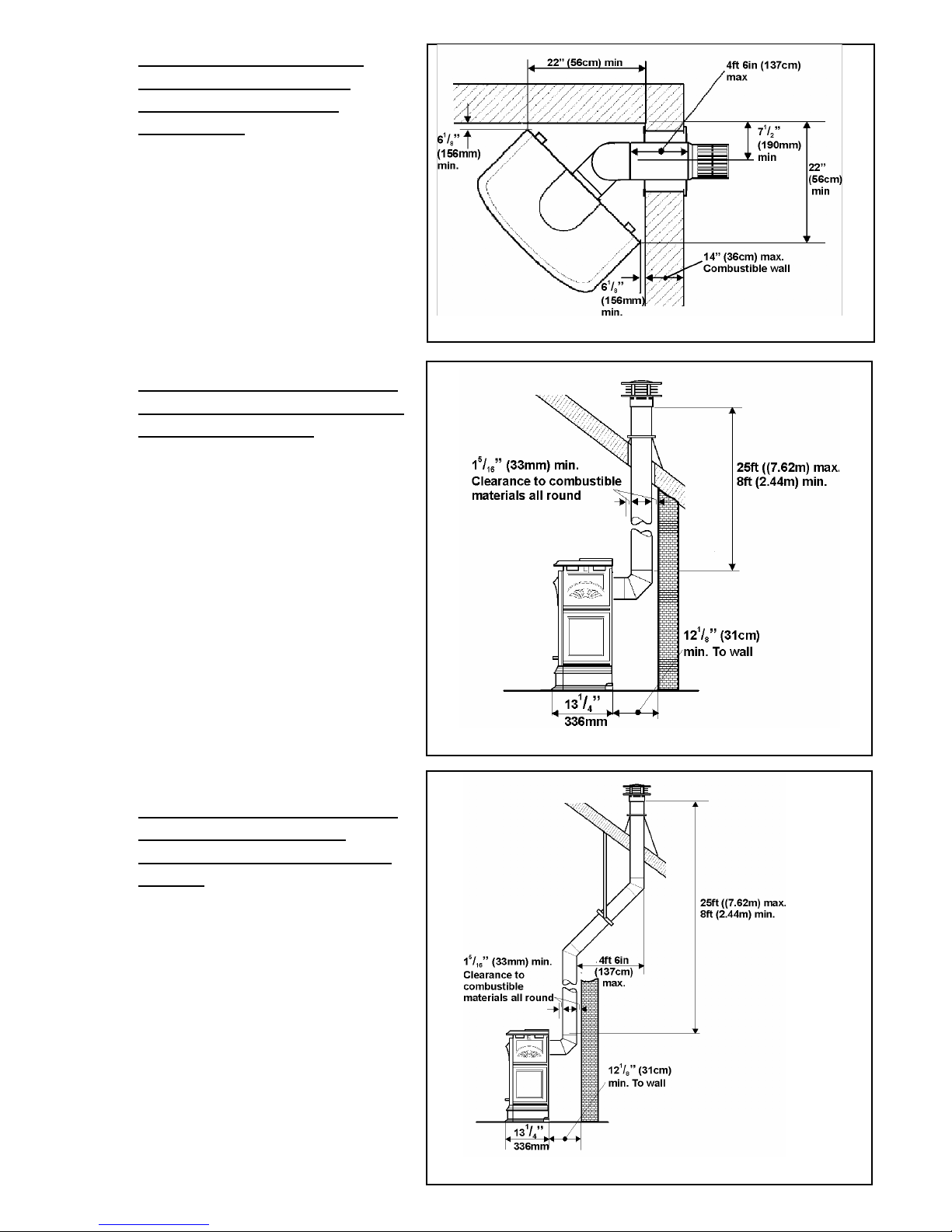
Figure 11
4.2.6 Corner location, rear vent
connection, vertical rise,
horizontal termination
(Figs 9 & 11)
Can be used with either #551DVK standard vent
kit or #984 Dura-vent terminal cap and accessories.
Adapter #817VAK, two 90° vent elbows #990B and
Dura-vent pipe lengths will be required.
(See venting options section of this manual).
No more than two 90°elbows must be used.
All vertical dimensional limits are as section 4.2.3.
Figure 12
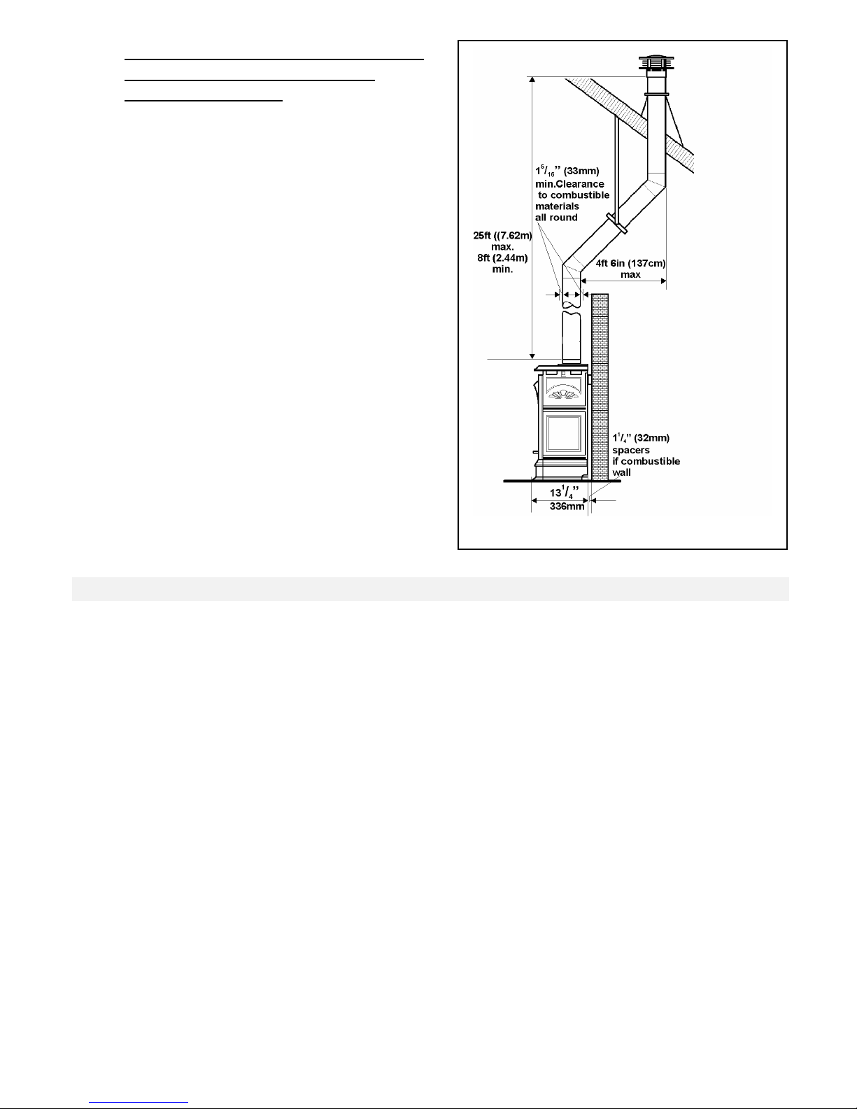
4.2.7 Rear vent connection, vertical
vent rise with through the roof
termination (Fig.12)
Adapter #817VAK, one 90° vent elbow #990B,
Dura-vent pipe lengths, a vertical vent terminal and
roof flashing will be required. Various other ceiling
or roof items may be necessary depending on the
particular installation (See venting options section
of this manual).
10 of 48
Figure 13
4.2.8 Rear vent connection, vertical
vent rise with offset and
through the roof termination
(Fig.13)
For situations where offset is necessary in
an attic to avoid obstructions or allow
useful space.
Adapter #817VAK, one 90° vent
elbow#990B, two 45° vent elbows #984,
wall straps, a vertical vent terminal, roof
flashing and Dura-vent pipe lengths will be
required. Various other ceiling or roof
items may be necessary depending on the
particular installation (See venting options
section of this manual).
4.2.9
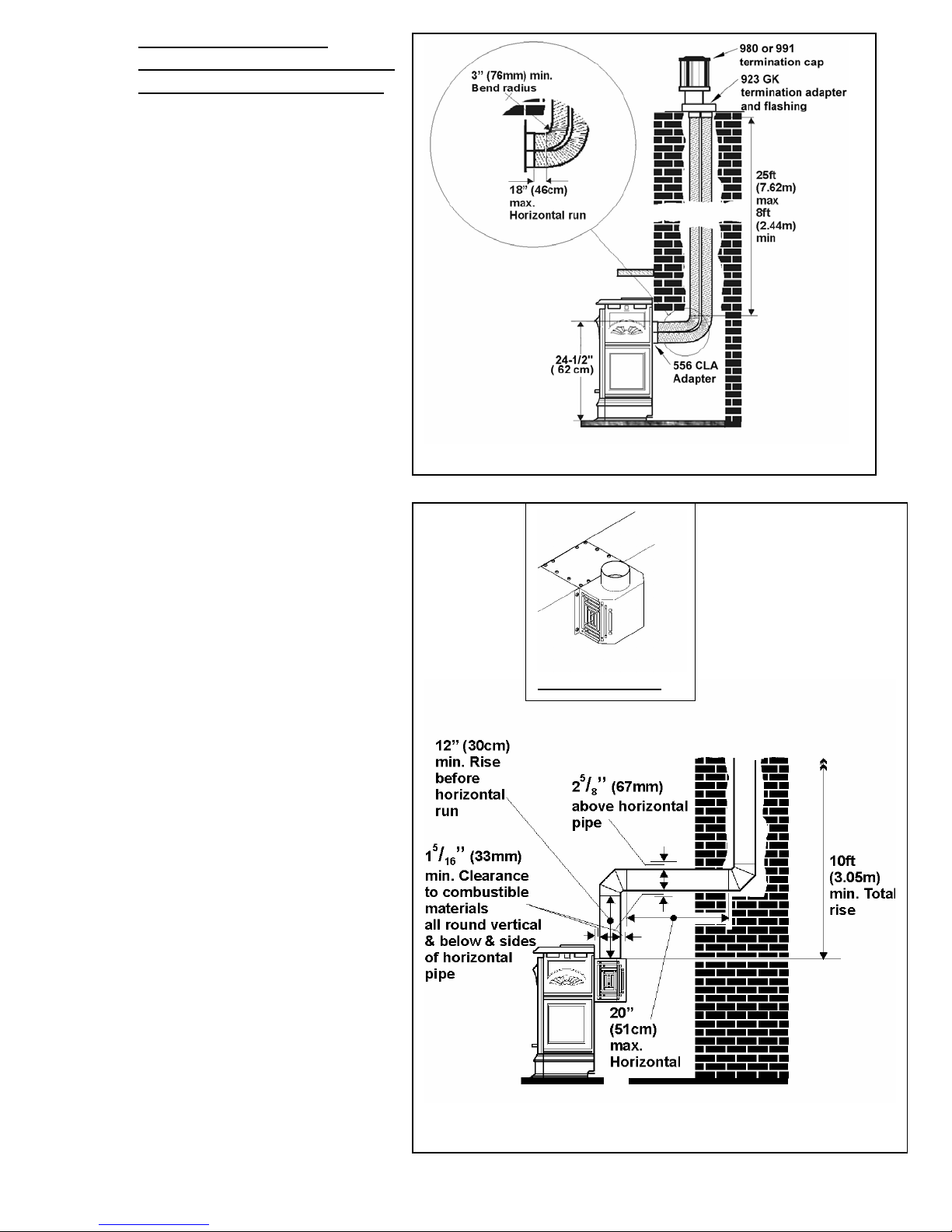
Rear vent connection,
installed to fireplace chimney
with co-linear liners (Fig.14)
Only for use when retrofitting a noncombustible fireplace and chimney.
The appliance must not be connected to
a chimney flue serving a separate solidfuel burning appliance.
Requires 556 CLA Co-Axial to CoLinear appliance adapter, two lengths of
3” dia. Flexible Chimney liner , colinear termination kit and flashing
#923GK and either high wind vertical
vent terminal cap #991 or a 980 Low
Profile vertical termination cap .(See
vent options section of this manual).
Figure 14
Fig 15.
552 BVK Adapter
4.2.10 Rear Vent Conversion to B-
Vent using 552 BVK Adapter
Free Standing Only ( Fig 15)
Used to field convert heater from direct
vent to 4” dia. gravity vent on free standing
units only . A full installation and operating
manual is supplied with the kit.
4.2.11
11 of 48
Top vent connection, vertical vent rise
with horizontal rear termination (Fig.16)
12 of 48
Can be used with either #551DVK standard vent kit or #984
Dura-vent terminal cap and accessories.
Adapter #817VAK, one 90° vent elbow #990B and Dura-vent
pipe lengths will be required.
(See venting options section of this manual).
No more than two 90°elbows must be used.
Minimum Maximum
A: From floor to top
of vent duct
4ft
(122cm)
11ft
(335cm)
B: Back of appliance
to inside wall
3
1
/4 in
(79mm)
-
C: Vertical pipe run 9in
(23cm)
8ft
(244cm)
D: Horizontal pipe
run
- 4ft 6in
(137cm)
E: Clearance to
combustible materials
above horizontal pipe
run
2
5
/8in
(6.7cm)
-
F: Clearance to
combustible materials
below horizontal pipe
run
15/16in
(3.3cm)
-
G: Clearance to
combustible materials
all round vertical pipe
run and at sides of
horizontal pipe run
1
5
/16in
(3.3cm)
-
Figure 16
4.2.12 Top vent connection, vertical
vent rise with horizontal side
termination (Figs.16 &17)
Figure 17
Can be used with either #551DVK standard
vent kit or #984 Dura-vent terminal cap and
accessories.
Adapter #817VAK, one 90° vent elbow #990B
and Dura-vent pipe lengths will be required.
(See venting options section of this manual).
No more than two 90°elbows must be used.
All vertical dimension, pipe run and clearance
limits are as section 4.2.11.
4.2.13 Top vent connection, vertical
vent rise with horizontal side
or rear snorkel termination
The dimensional requirements in sections
4.2.11 and 4.2.12 apply.
Adapter #817VAK, one 90° vent elbow #990B, Dura-vent pipe lengths and a Dura-vent snorkel termination will be
required.
#942 Dura-vent thimble kit may also be necessary.
(See venting section of this manual).
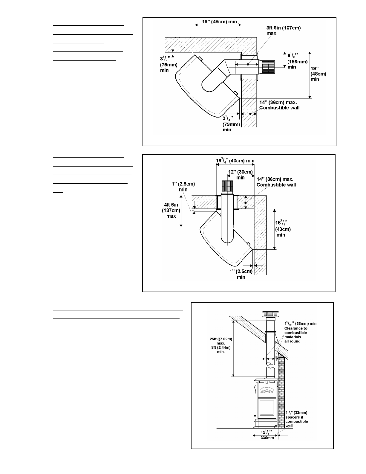
Figure 18
4.2.14 Top vent connection,
corner location, vertical
rise, horizontal
termination, 45° pipe
bend (Figs 16 & 18)
Can be used with either #551DVK
standard vent kit or #984 Dura-vent
terminal cap and accessories.
Adapter #817VAK, one 90° elbow #990B,
one 45° elbow #945B and Dura-vent pipe
lengths will be required. (See venting
section of this manual).
All vertical dimensions and clearance limits
are as section 4.2.11.
4.2.15 Top vent connection,
corner location, vertical
rise, straight horizontal
termination (Figs 16 &
19)
Figure 19
Can be used with either #551DVK
standard vent kit or #984 Dura-vent
terminal cap and accessories.
Adapter #817VAK, one 90° elbow #990B
and Dura-vent pipe lengths will be
required. (See venting section of this
manual).
All vertical dimensions and clearance limits
are as section 4.2.11.
.
Figure 20
4.2.16 Top vent connection, vertical vent rise,
through the roof termination (Fig. 20)
Adapter #817VAK, Dura-vent pipe lengths, a vertical vent
terminal and roof flashing will be required. Various other
ceiling or roof items may be necessary depending on the
particular installation (See venting options section of this
manual).
13 of 48
4.2.17 Top vent connection, vertical vent rise
with offset and through the roof
termination (Fig.21)
For situations where offset is necessary in an attic to avoid
obstructions or allow useful space.
Adapter #817VAK, two 45° vent elbows #984, wall straps, a
vertical vent terminal, roof flashing and Dura-vent pipe lengths
will be required. Various other ceiling or roof items may be
necessary depending on the particular installation (See venting
options section of this manual).
Figure 21
14 of 48
15 of 48
5.0 LOCATION –ZERO CLEARANCE
5.1 Framing -General
The framing dimensions vary with the different cast iron fronts and with different vent configurations, allowing for
elbows etc. Read framing drawings carefully.
5.2 Finishing- General
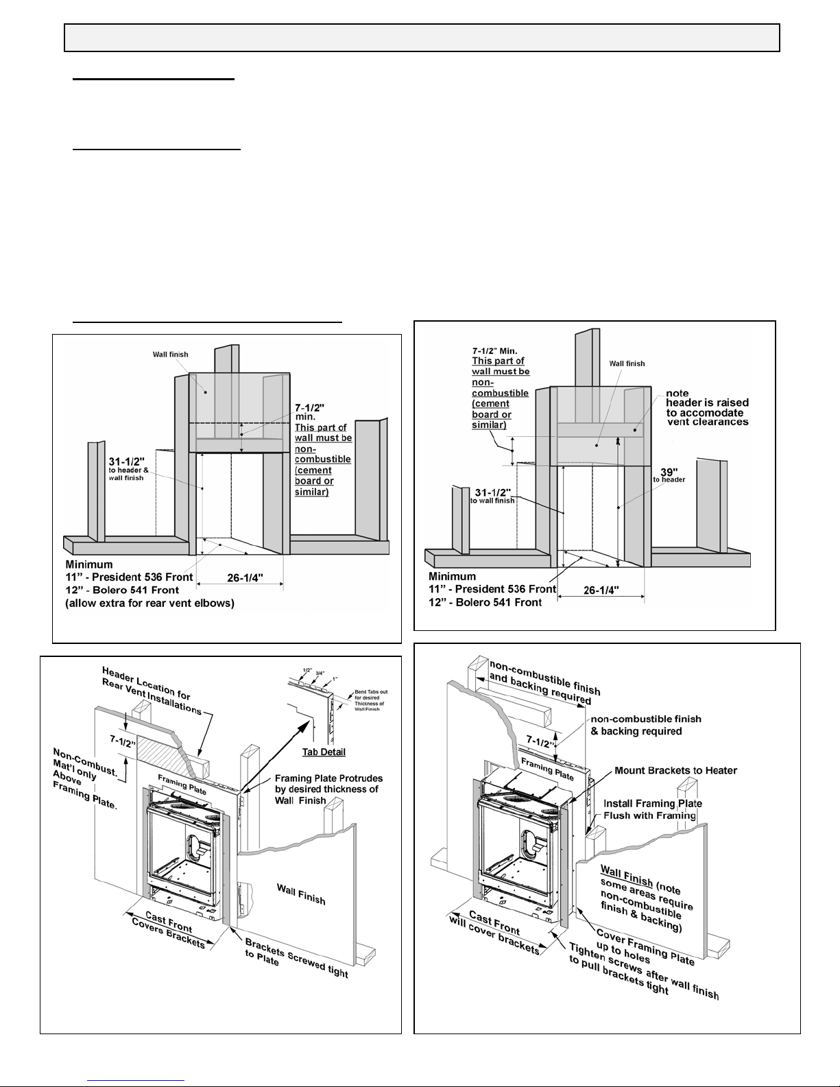
The President 536 and Bolero 541 Fronts come supplied with a Framing Plate for zero clearance applications. The
Framing Plate is painted black and may be left exposed beyond the perimeter of the of the cast iron front or may be
covered with non-combustible material if desirable ( see figs 24 &25 ). Windsor Arch 539 Front comes with an integral
back plate ( see fig 3)
• A non-combustible hearth is not necessary in front of this appliance.
• The appliance is approved to install directly on wood sub- flooring
• Any framing construction must be clear of standoffs (See figures 1-4 ).
• Be aware of the area 7
1/
2
” x 26¼” (19cm x 67cm) immediately above the Framing Plate used with the 536/541 Cast
Fronts must be constructed with non-combustible materials as shown in figures ( 22 &23 ).
5.3 President 536/ Bolero 541 Fronts
Fig 23 , Top Vent Framing, 536/541 Fronts.
Fig 22, Rear Vent Framing, 536/541 Fronts
Fig 25, Framing Plate covered, 536/541 Fronts
Fig 24, Framing Plate Exposed, 536/541 Fronts
 Loading...